Proceeding Paper

Robust Frequency-Decoupling-Based Power Split of Battery/Supercapacitor Hybrid Energy Storage Systems in DC Microgrids †

1
Sustainable Development and Computer Science Laboratory SDCS-L, Ahmed Draia University, Adrar 01000, Algeria
2
Smart Grids & Renewable Energies Laboratory SGRE-L, Tahri Mohamed University, Bechar 08000, Algeria
3
Laboratory of Instrumentation and Materials Applied (LIMA), Nour Bachir University Center, El Bayadh 32000, Algeria
4
Laboratoire Gènie Electrique et Energie Renouvelable (LGEER), Hassiba Benbouali University, Chlef 02000, Algeria
5
School of Science, Computing and Engineering Technologies, Swinburne University of Technology, Hawthorn, VIC 3122, Australia
*
Author to whom correspondence should be addressed.
Presented at the 1st International Conference on Physics of Semiconductor Devices, Renewable Energies and Environment, Bechar, Algeria, 14–16 November 2022.
Phys. Sci. Forum 2023, 6(1), 6; https://doi.org/10.3390/psf2023006006
Published: 21 June 2023

Abstract

:
A frequency-decoupling-based power split was used in this study to manage a direct-current microgrid (DC-MG)-based PV and hybridized energy storage system (HESS), which consisted of a battery and a supercapacitor. The HESS control integrated a dual-loop structure for bus voltage regulation and recovery and HESS charge/discharge control. Hysteresis current control (HCC) tracked the supercapacitor setpoint current using low-pass filtering (LPF) control. The system reliability was assessed using pulsing, smooth, and disturbed PV and load waveforms with standard and advanced LPF methods. The Matlab simulation results confirmed a superior HESS control performance under varying resource waveforms. Key performance indexes (KPIs) were used to evaluate the bus voltage, HESS current management, loading efficiency, and loading mismatch.

1. Introduction

The world’s electricity services are improved daily due to the implementation of advanced communication technologies, intelligent control, and energy management strategies (EMSs) to tackle resource uncertainties or unpredicted failures of system supply.
Several power systems combine conventional and renewable energy resources (RERs), energy storage system (ESS) technologies, and backup resources to ensure reliable power systems with a continuous and efficient supply.
Among the known micro-power systems with a low operating voltage and power, MGs or nanogrids (NGS) are currently being adopted in isolated zones and for remote applications, especially those lacking main grid lines. Such advanced power systems are potential solutions for linking several consumers with clean, renewable, and secure power [1,2].
According to the ANSI C84.1 standard [3], the low-voltage class of MGs (LV-MGs) is below ≤1000 V, which offers numerous advantages for reducing power distribution losses (consumers are near the production system) and connecting with other nearby MGs, forming a cluster of MGs to improve the overall reliability and autonomy [2,4]. Using the clean energy of MGs reduces greenhouse gas emissions that cause environmental pollution.
As vital components in power systems, various energy storage technologies are essential resources to ensure the autonomy of stationary power systems such as MGs [5,6] and advanced vehicles [7,8], including terrestrial, marine, and air automobiles [6,9,10].
ESS technologies vary based on their maturity, performance in different weather conditions (mainly temperature), lifespan or life cycles, energy/power densities, weight, and cost-effectiveness. In this regard, electrochemical lead–acid (LA) batteries represent the oldest and most mature technology on the market, and they are more suitable for stationary power systems due to their low cost and availability [2].
Instead, lithium-ion (Li-ion) battery technology is among the latest energy storage technologies, and they outperform LA batteries with their lightweight property, high energy density, high cell voltage, and reduced charge losses [1,11]. In contrast, Li-ion batteries are highly cost-effective, sensitive to high temperatures, and suffer from the risk of bursting.
Supercapacitors (SCs) [12] are charge storage devices that function due to their electrochemical and electrostatic operation processes. SCs are adopted for PV systems to smooth their outputs and overcome the limitations of alternative batteries, especially the limitations of a low power density and a sensitivity to high temperatures [13].
Such SCs have reduced sizes with high capacitances, offer high power densities compared to LA and Li-ion batteries, enable fast charging/discharging, and are eco-friendly without producing polluting gas emissions. However, SCs suffer from a low energy density (3–5 Wh/Kg), a higher self-discharge rate compared with above battery technologies, and a low cell voltage, requiring series connections to adapt to higher voltage systems.
Power systems require supply voltage stability to enable smooth power exchange among resources and load requirements. Thus, using controllable devices, power electronic devices, or DC–DC power converters is inevitable for adapting resource outputs with the setpoint voltage of the load.
In battery applications, DC–DC bidirectional converters (BDC) allow the charge/discharge of energy and a reversed current circulation between batteries and the load DC bus bar. In [14,15], several topologies and control methods of non-isolated DC–DC converters in RE applications were reviewed. Numerous contributions are addressed in the literature for HESS control and EMS [16], including model predictive control (MPC) [17,18,19], a fuzzy logic controller (FLC) [20], optimal LQR [21], and CPI versus super-twisting sliding mode controllers (ST-SMCs) [5].
In light of this short overview, this paper proposes a DC-MG-based PV and HESS combining a Li-ion battery with SCs to supply a pulsing load demand, as seen in Figure 1.
The DC-MG adopts a DC-coupling configuration with a single-point-of-failure or DC bus rated at 250 (V) with a peak sharing of power of 30 (Kwp).
The system operates with two levels of decentralized energy management and monitoring strategies (EMMSs). The first treats the output measurements of distributed energy resources (DERs), including currents, voltages, powers, and states of charge (SoCs), and specifies the operation of the PV plant (maximum power point tracking (MPPT) control), the batterycharge–discharge control (dual-loop control), and the SC charge/discharge control (HCC with LPF control). Then, the second level receives setpoints from the first level above and includes the local controllers (LCs) of DERs, which control the DC–DC converters and generate their PWM signal commands.
Equation (1) expresses the total powers of the system resources ΔPDC-MG collected at the DC bus and delivered to the load using Kirchhoff’s current and voltage rules.
ΔPDC-MG = (PPV ± PBESS ± PSC) − PLOAD = VDC-BUS × IDC-BUS
The bus voltage and current are noted by VDC-BUS and IDC-BUS, while the powers of the load, the PV, the SC, and the battery are noted by PLOAD, PPV, PSC, and PBESS, respectively.

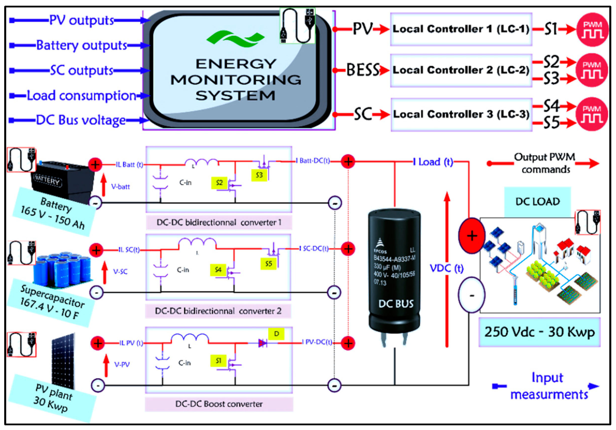
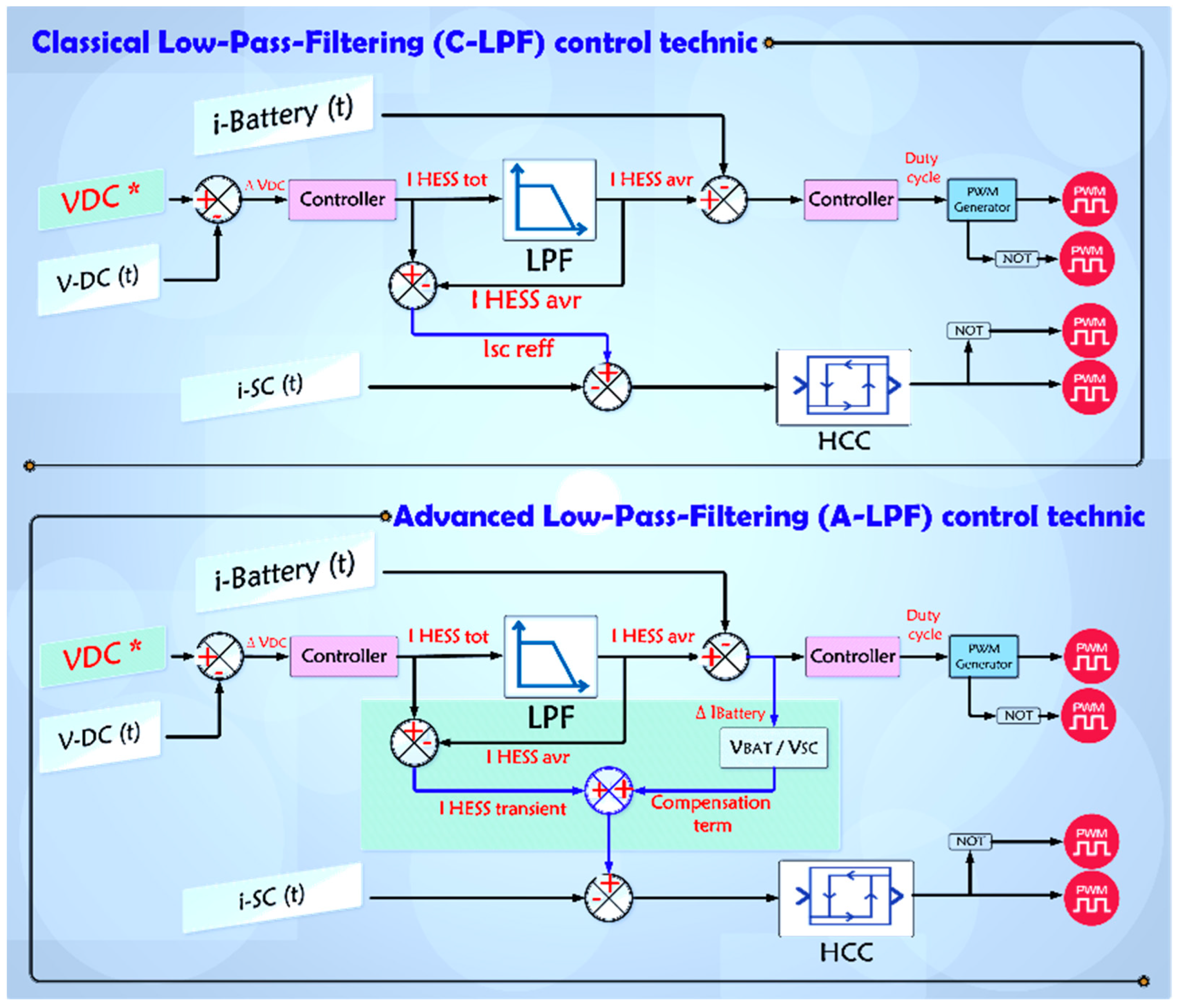
2. System Control Structure

The control framework in Figure 2 consists of the FD-SP control, adopting CPI with the LQR-I controllers in the battery’s dual-loop control, while a hysteresis current controller (HCC) is used to track the SC setpoint currents.
To achieve the proper allocation of HESS banks with the suitable part of the load demand, a frequency-decoupling-based power-split (FD-PS) control is used in this paper. The FD-PS allows for preserving the life cycles of HESS banks and reducing stress on the slow battery dynamic. The FD-PS includes a classical low-pass filter (C-LPF) approach with a first-order continuous-time filter to disaggregate the load setpoint power into a slow part for steady-states and fast parts during transients.
V D C = V D C R e f V D C t i L B E S S R e f   1 = L P F V D C . K P v + K I v s i L S C R e f   1 = i H E S S T o t a l i L B E S S R e f   1 i L B E S S = i L B E S S R e f   1 i L B E S S t D u t y   c y c l e R e f = i L B E S S . K P i + K I i s
The errors in the outer voltage V D C and inner current loops i L B E S S are presented in Equation (2) using CPI, with the setpoint currents of the battery i L B E S S R e f   1 , the SC i L S C R e f   1 , and the duty cycle D u t y   c y c l e R e f using the C-LPF control.
The advanced method (A-LPF) aims to solve the issue of slow bus voltage recovery and applied stress on the battery due to its slow response and low dynamic. The SC provides uncompensated battery power P B E S S U n c o m p in Equation (3) using the new setpoint current i L S C R e f   2 to improve the load convergence and bus voltage recovery speed.
i L S C R e f   2 = i L S C R e f   1 + V B E S S V S C . i L B E S S P B E S S U n c o m p = V B E S S . V B E S S V S C . i L B E S S
Equation (4) explains the CPI controller design using the voltage and current bandwidths ωv = ωi/10 and ωi = sampling frequency/10; D denotes the steady-state duty cycle; L and C are the converter inductance and capacitance, respectively; η varies between 0.1 and 0.2; and VDCREF is the setpoint DC bus voltage [20].
K p V d c = ω V . C / 1 D , K i V d c = K p V d c . η . ω V D C K p i L = ω i . L / V D C R E F , K i i L = K p i L . η . ω i L
Otherwise, KP and KI are computed using the ‘SISOTOOL’ feature in the Matlab control system toolbox for single-input–single-output (SISO) systems.
To control the CPI gains of the DC–DC bidirectional converter, the transfer functions (TFs) of the converter’s linearized modes are required. Equation (5) presents the outer loop TF G V D C i L B A T , from iLBAT to VDC, and the inner current loop G i L B A T d B A T , from the average duty-cycle values (dBAT) to the average current values (iLBAT):
G V D C i L B A T = V DC ( s ) i L B A T ( s ) = L B A T . R LOA D . iL B A T . s + V DC . R LOA D . ( 1 D B A T ) V DC . R LOAD . C DC . s + V DC + ( 1 D B A T ) . R LOAD . iL B A T G i L B A T d B A T = i L B A T ( s ) d B A T   ( s ) = V DC . R LOAD . C DC . s + V DC + ( 1 D B A T ) . R LOAD . iL B A T L B A T . C DC . R LOAD . s 2 + L B A T . s + ( 1 D B A T ) 2 . R LOAD
LBAT, CDC, RLOAD, and DBAT denote the battery inductance (H), bus bar capacitance (F), the equivalent load impedance (Ω), and the BDC averaged duty cycle (%), respectively.

3. Results and Discussion

In this section, the HESS system was simulated using Matlab Simulink to assess the performance of the proposed control structure. The results are presented and discussed, where Table 1 below presents the main scenarios for the simulations.
The proposed scenarios highlight the contribution of the HESS in enhancing supply stability and reliability, adopting the C-LPF and A-LPF under pulsing, smooth, and perturbed waveforms of PV generation and load demand.
The first result shows the power balance profiles of the DC-MG system using pulsing, smooth, and perturbed waveforms, as seen in Figure 3.
As shown, the stability of the load supply varied when using the pulsing, smooth, or perturbed PV generation and the load demand. The HESS compensated for the power imbalances between the PV and the load, while the SC dealt with transients or high-frequency parts of the load, and the battery flattened steady-state load parts. The resulting power imbalances and the load divergence on its setpoints affected the system’s bus voltage stability regarding the transient overshoot/undershoot settling time and recovery speed. Stability metrics reflect the status of clustered powers feeding load requirements.
Figure 4A–C showcases the system’s bus voltage profiles compared to the SC power and the overall system power losses using the C-LPF and A-LPF control methods.
As a comparison, the system’s stability and reliability were higher under smooth and seamless waveforms of PV generation and load demand compared to the pulsing waveforms, which required higher SC peaks of power to mitigate the spikes in the current and power for the battery and the load. Instead, the system was more destabilized when using perturbed waveforms with high-frequency issues, causing more stress on HESS and load supply, although the bus voltage was maintained within its standardized limits (±5%).
In other words, the system’s transient and steady-state stabilities were examined, and the results showed superior stability for smooth profiles, while lower stability and reliability were attained when using an uncertain power quality.
Table 2 summarizes the approximated operation thresholds of the power losses, SC power, and bus voltage under the proposed power quality waveforms.
As seen in the highlighted periods [1–1.35], [7.99–8.1], and [8.99–9.1] (sec), the bus voltage stability was proportionally affected by the SC outputs using the two LPF technics. The bus voltage was smoother with reduced overshoots and rapid recovery when using the A-LPF, which minimized power losses and enhanced the load supply efficiency.
The HESS current control using the C-LPF and A-LPF revealed different performances regarding transient (SC current) and steady-state (battery current) regimes. As seen in Figure 5A–C, the control robustness was evaluated based on the accuracy and precision of tracking the battery’s and SC’s setpoint currents. The control accuracy was observed in banks’ current profiles, with varying performances during transient and steady states, as emphasized during same periods, [1–1.35], [7.99–8.1], and [8.99–9.1] (sec).
The resulting power imbalances were covered by the transient SC spikes of currents and then flattened by battery-lagged currents using LPF technics. The rapid bus voltage recovery was controlled by the amplitude of the SC current peaks using the A-LPF, enabling rapid loading convergence to its setpoints with minimized power losses.
In contrast, the C-LPF resulted in a less accurate current control, a slower bus voltage recovery, and more power losses. For steady states, the battery current illustrated the stress on the battery to compensate for power imbalances using normal and abnormal power waveforms.
Using the A-LPF, the SC improved the control dynamic and system reliability by dealing with the uncompensated battery power.
To highlight the control robustness, Figure 6 presents the duty cycles obtained from the dual-loop control structure (inner current loop) during the six proposed scenarios. The influence of the LPF control methods was highly observed in the SC converter duty cycle, reducing the battery’s stress and supplying a stable and reliable load demand.
Figure 7 shows the SoC profiles of HESS banks, highlighting the influence of the LPF on the banks’ energy usage. Similar to Figure 6, the battery SoC was less affected due to its low power density (LPD), avoiding rapid charges/discharges compared with the SC.
Thus, the SC SoC was more stressed when using the A-LPF method. The additional drained SC power improved the load supply and the battery’s slow dynamic. Besides, the stress applied to the SC was represented in duty cycle and SoC profiles due to its high-power density (HPD), enabling a fast charge/discharge to meet high-frequency load parts.
Finally, an assessment of DC-MG reliability was achieved under the proposed waveforms and the LPF control method.
To summarize, the tabulated numerical values of the key performance indexes (KPIs) in Figure 8 consist of the root mean square error (RMSE), the mean absolute error (MAE), and the integral square error (ISE), representing the precision, accuracy, and robustness of the HESS control, respectively.
The KPIs analyzed the system’s bus voltage regulation and recovery, the battery/SC current control, the minimization of the overall power loss, and the loading divergence to its setpoints.
To conclude, the KPIs of the revealed results confirmed the following:
  • The proposed system is feasible with the control and energy management strategies.
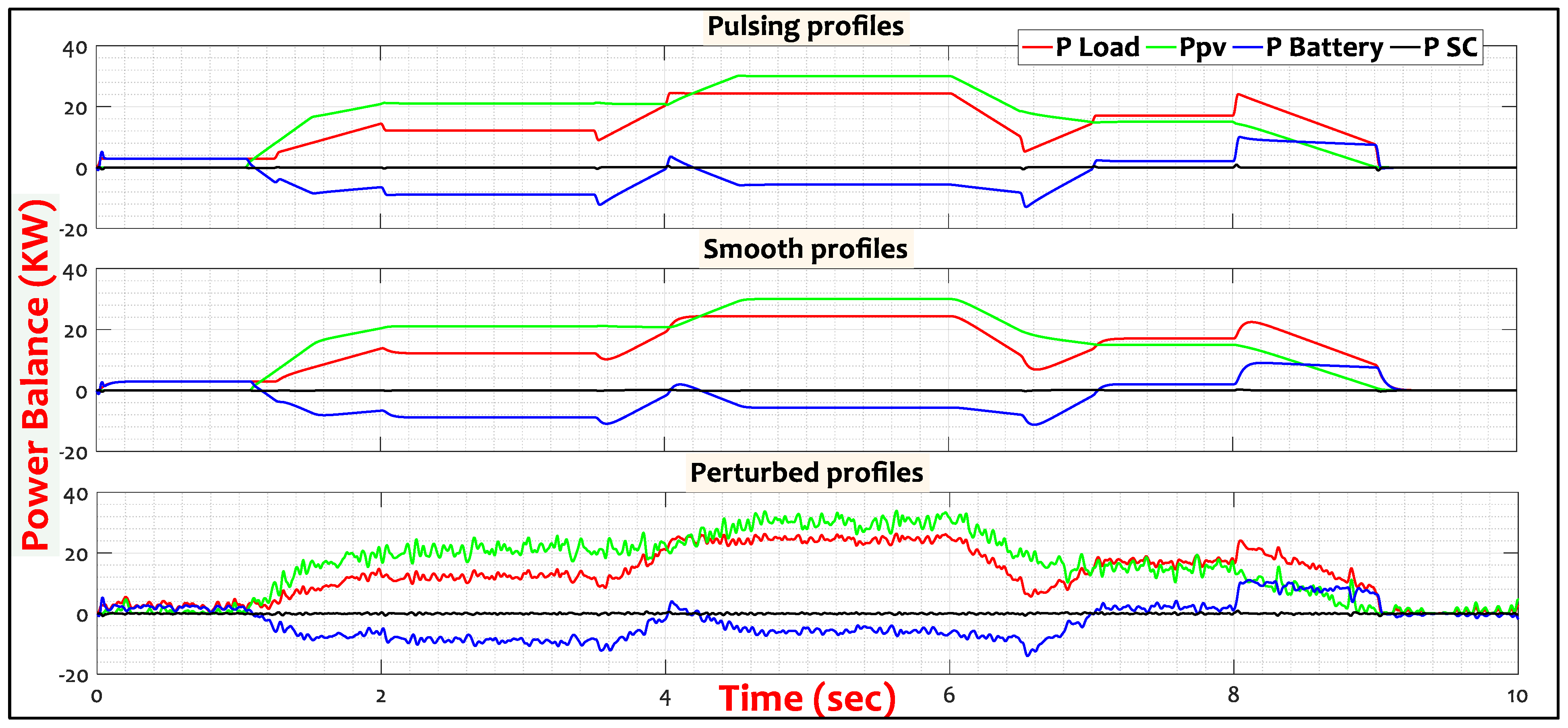
  • The system has good reliability against proposed waveforms of PV and load powers.
  • The high HESS control performance compensated for loading mismatch under different power quality waveforms.
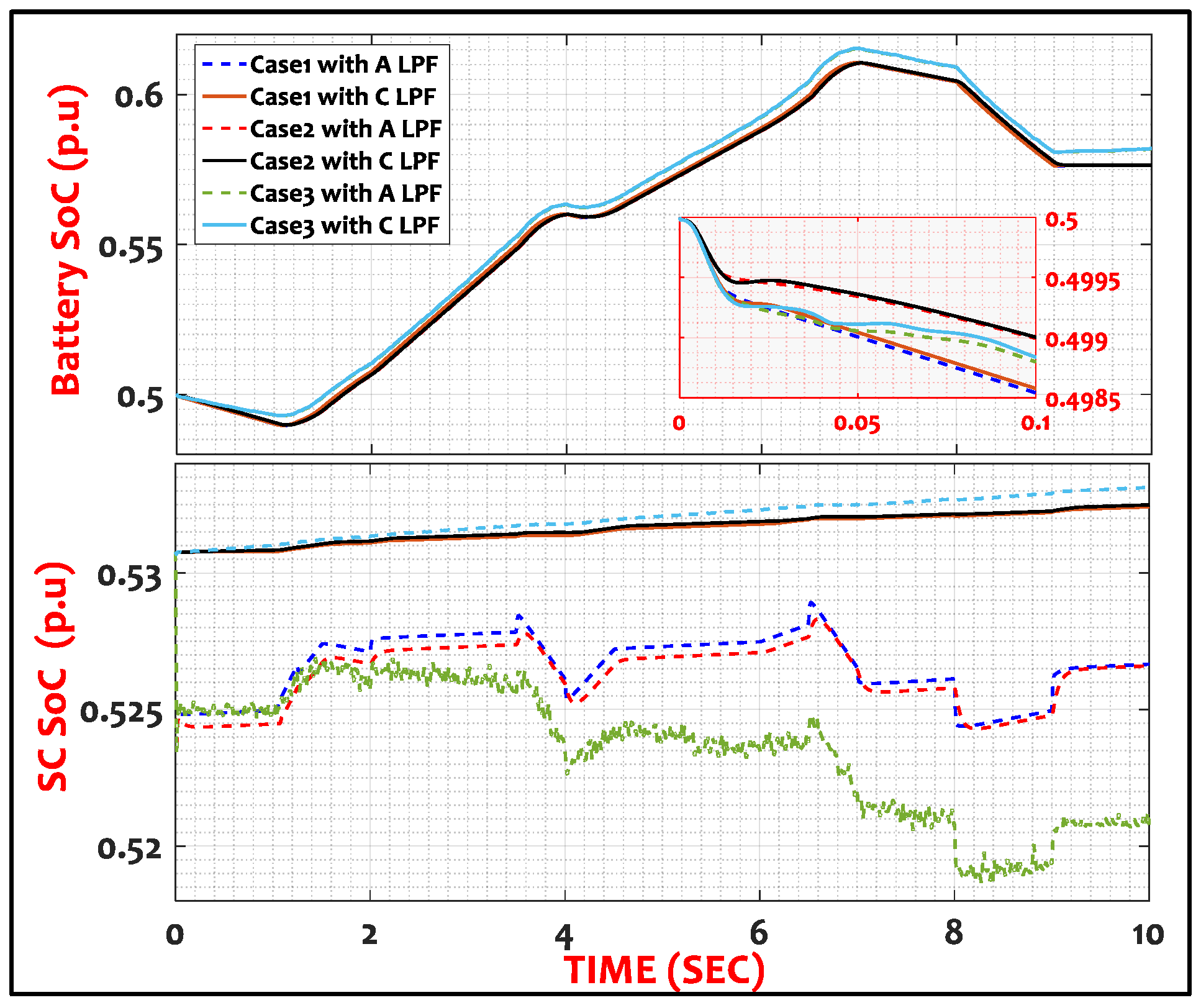
  • The superior operation and control accuracy of the HESS using the A-LPF improved the loading efficiency, conserved the battery dynamics, and extended the overall HESS lifespan.
  • Since the system control revealed a superior performance under smooth waveforms, the system reliability was enhanced using the A-LPF compared to the C-LPF method.
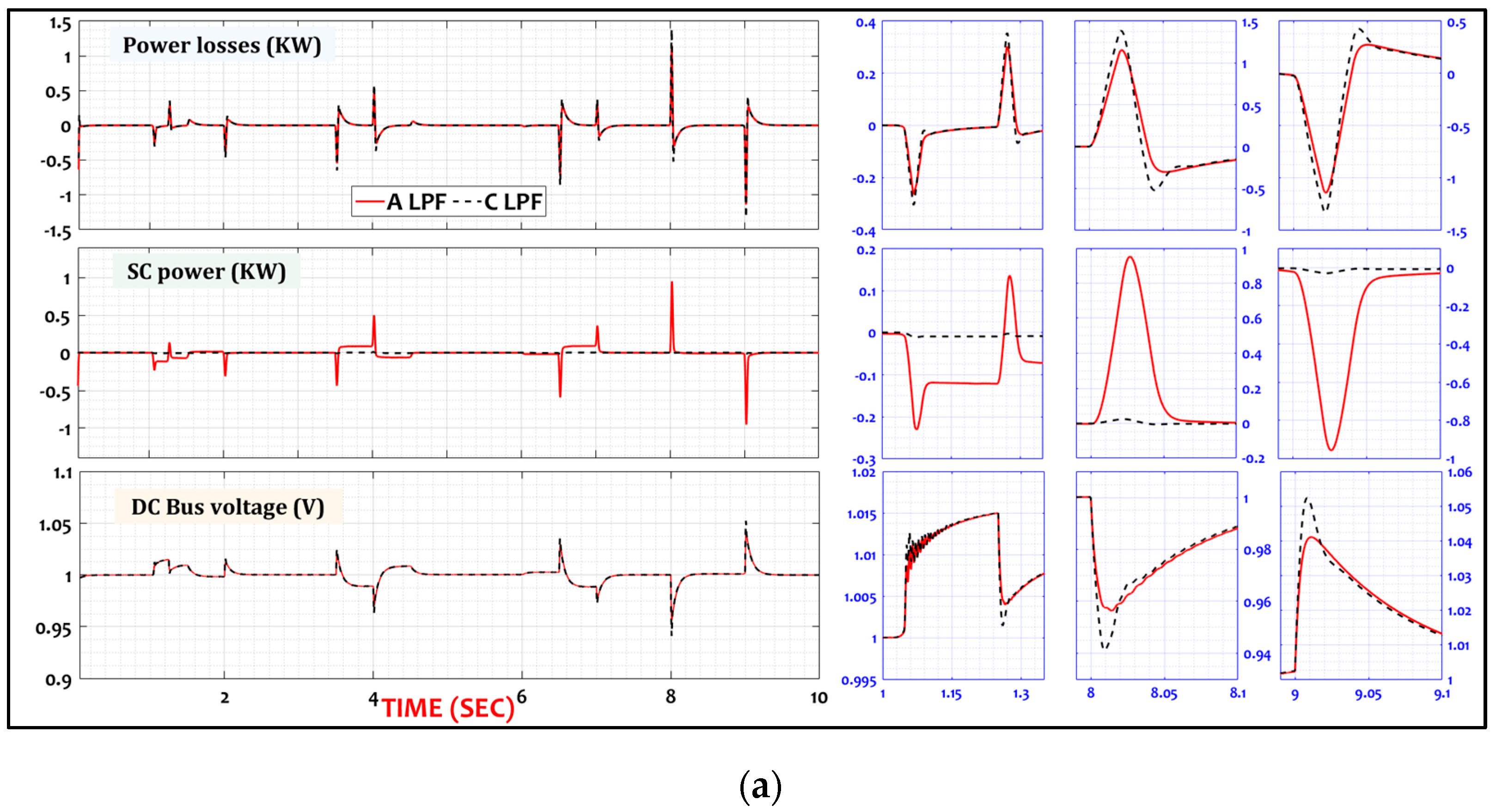
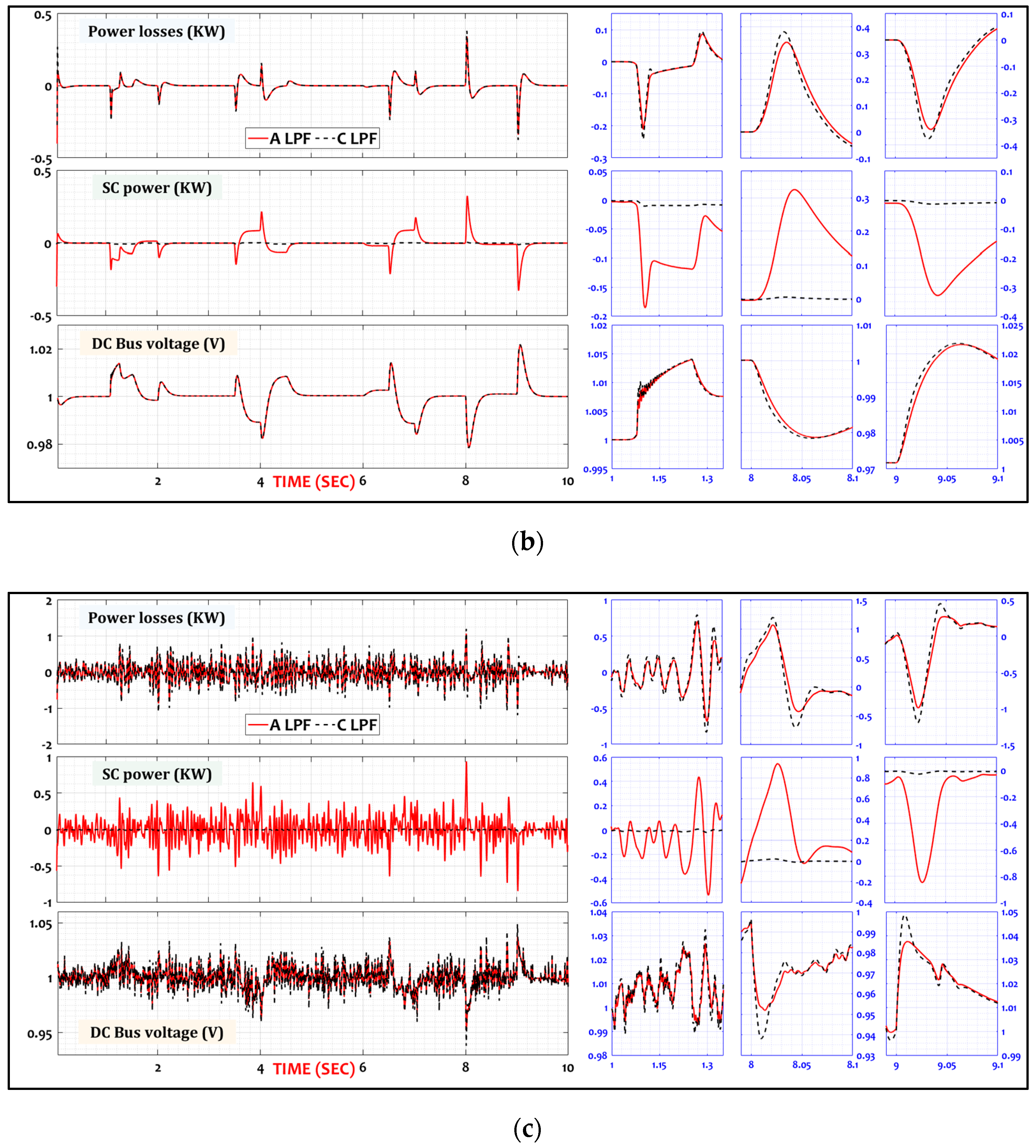
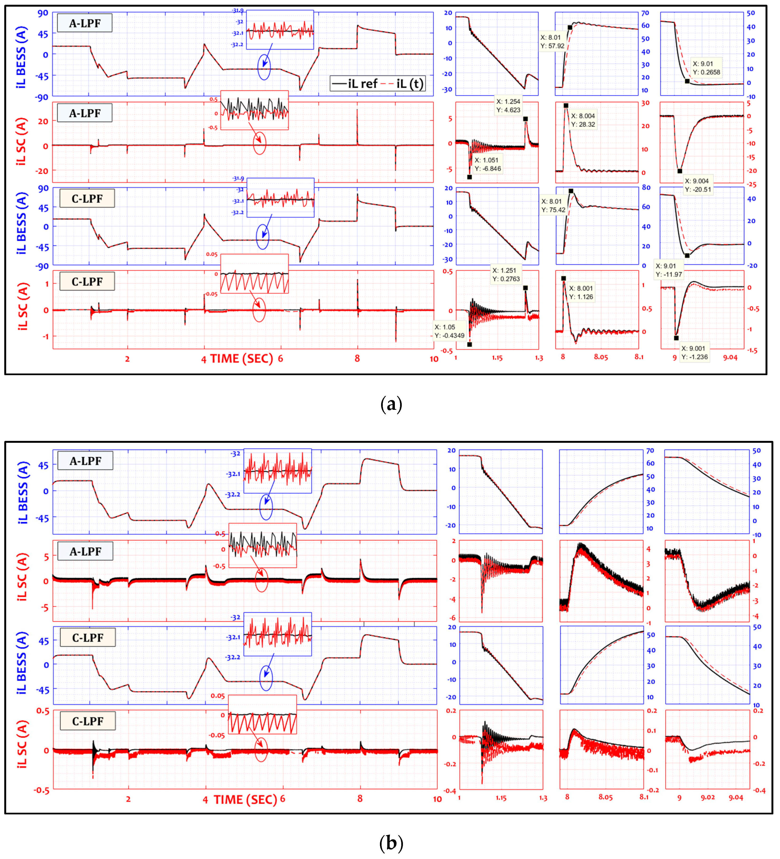
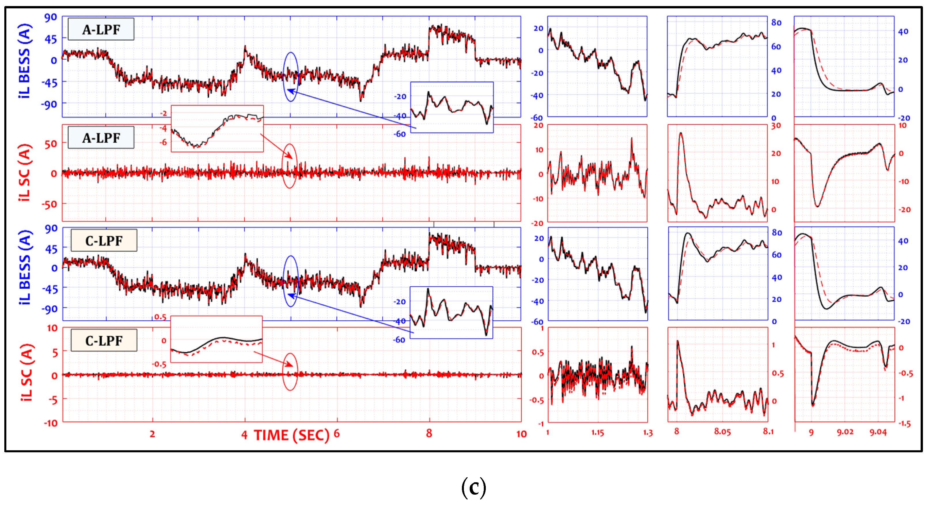
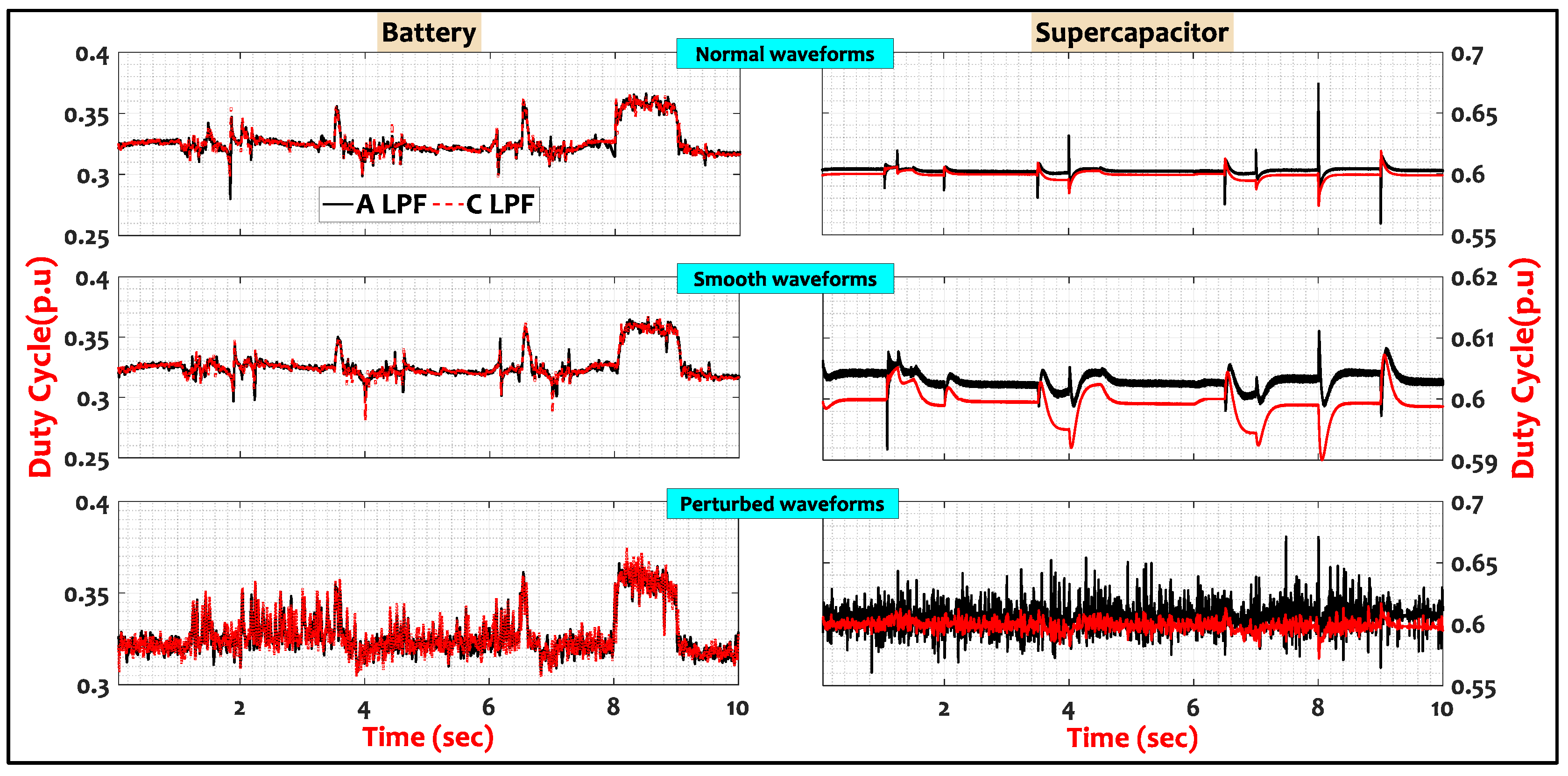
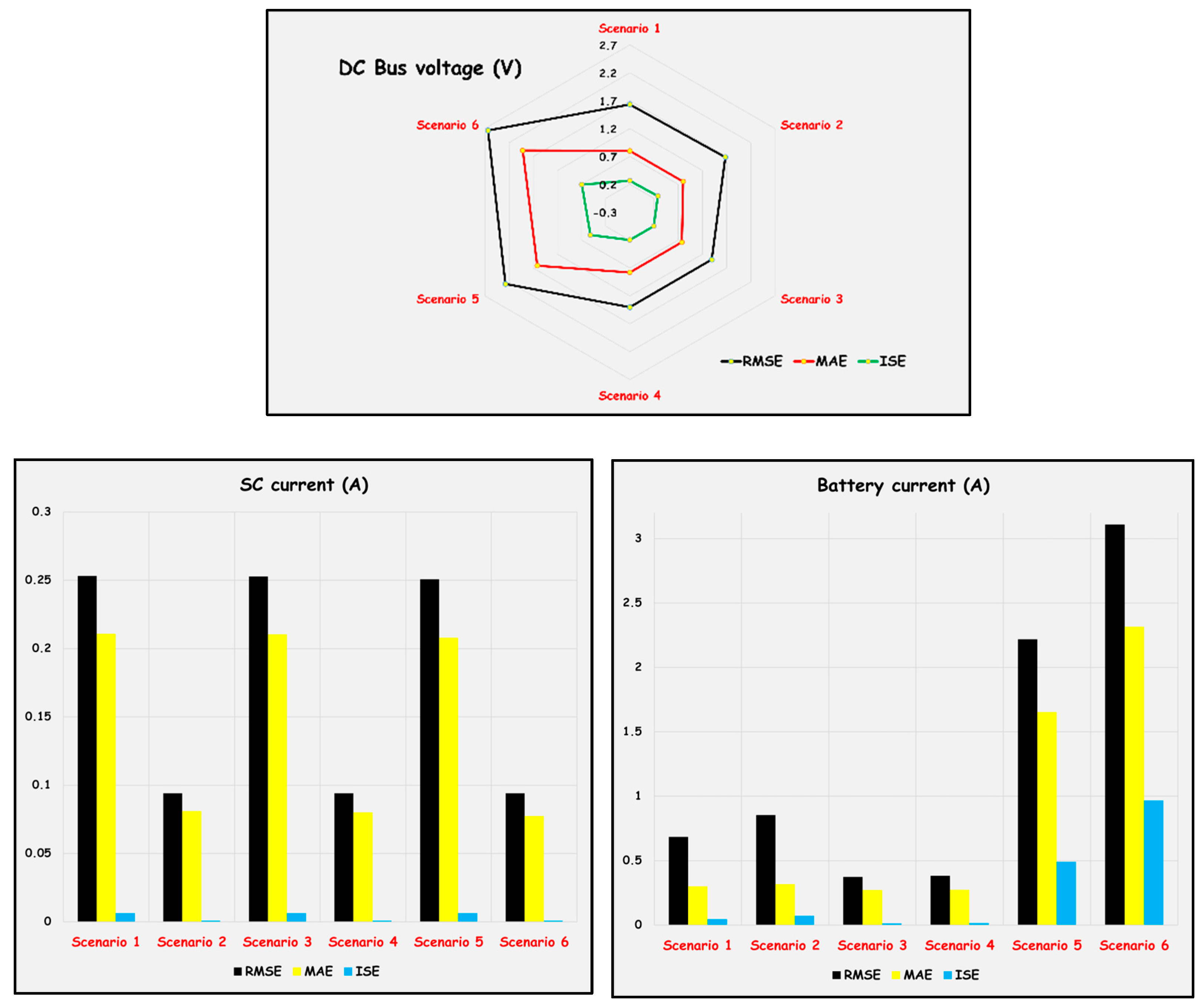
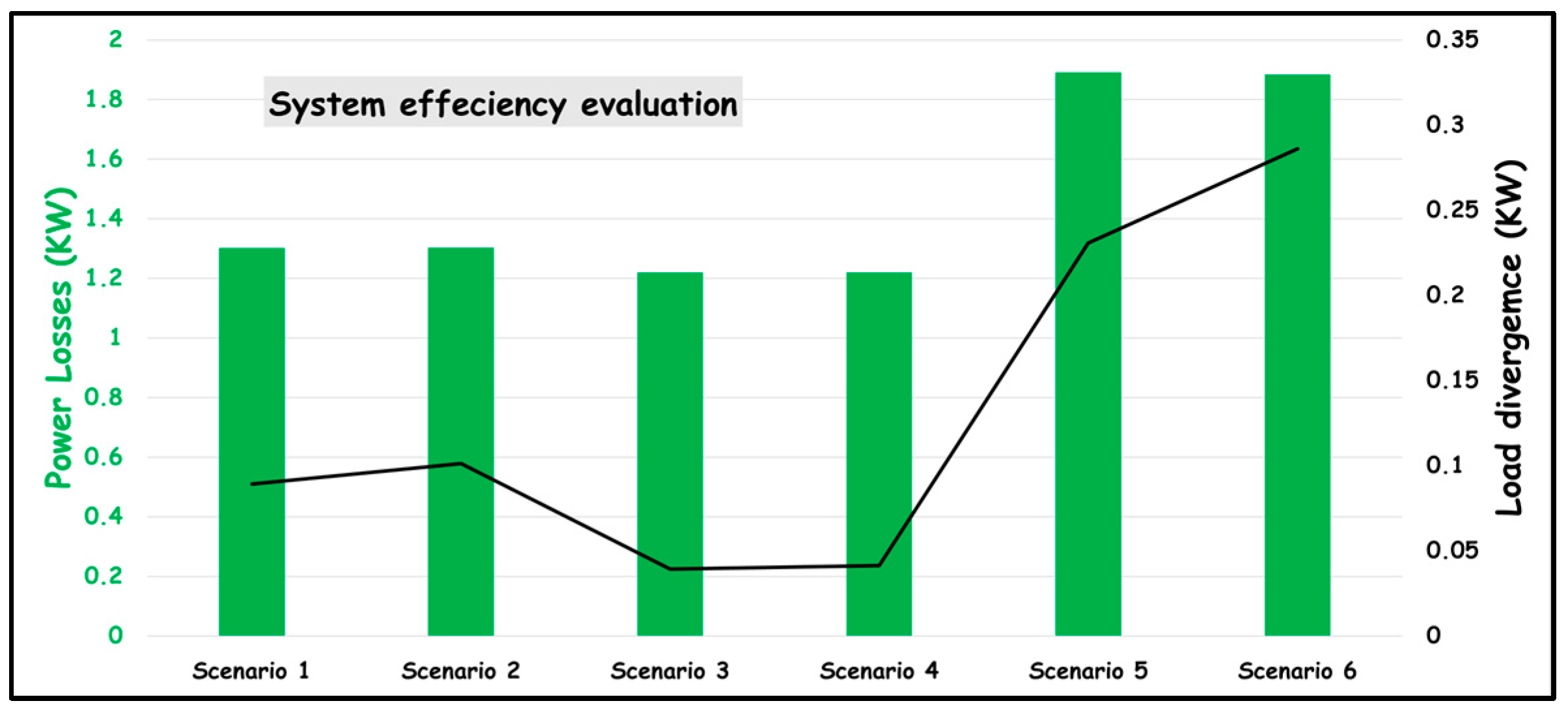
  • The use of the A-LPF method improved the bus voltage stability by 1.39% and increased the control accuracy by 0.378 and 0.09% for the battery and SC, respectively, while the system supply efficiency was raised by 1.2% and the load convergence was enhanced by 0.04%.
  • Compared to the pulsing waveforms (scenarios 1 and 2), the use of smooth waveforms (scenarios 3 and 4) revealed advances of 1.62% for the bus voltage and 0.68 and 0.25% for the battery and SC current control, respectively, while system power losses were reduced by 1.29% and the loading convergence was improved by 0.09%.
  • In contrast, the perturbing waveforms (scenarios 5 and 6) disturbed the bus voltage by 1.61% and the battery and SC current control by 0.62 and 0.25%, respectively, while the system power losses increased by 1.28% and the loading convergence dropped by 0.09%.

4. Conclusions

This brief paper presented frequency decoupling based on classical and advanced LPF technics and discussed HESS for DC-MG applications. The bidirectional battery power-sharing was controlled via a dual-loop control structure using CPI controllers, while the charge/discharge of the SC was managed by an HCC in a single-current closed loop using LPF techniques.
During simulations, the A-LPF and C-LPF were compared regarding the transient and steady-state performance of the HESS control, considering the stability of the system’s bus voltage, the banks’ current control, the overall power losses, and the divergence on load setpoints.
The analyses of the Matlab results revealed a superior control performance when using the LPF methods, as illustrated by the KPIs in terms of the RMSE, MAE, and ISE.
The obtained improvements were due to the robustness of the HESS control, considering that the uncompensated battery power was covered by the SC. Thus, the improved operation and control precision of the HESS utilizing the A-LPF enhanced the loading efficiency, conserved the battery dynamics, and prolonged the HESS’s overall lifespan.

Author Contributions

Conceptualization, M.A.H. and A.B.; methodology, M.A.H.; software, M.A.H.; validation, M.A.H., O.A., A.B. and S.M.; formal analysis, M.H.; investigation, M.A.H.; resources, M.H.; data curation, M.A.H.; writing—original draft preparation, M.A.H.; writing—review and editing, M.A.H. and A.B.; visualization, M.H.; supervision, M.H. and B.A.; project administration, M.H.; funding acquisition, M.A.H. and A.B. All authors have read and agreed to the published version of the manuscript.

Funding

This research received no external funding.

Institutional Review Board Statement

Not applicable.

Informed Consent Statement

Not applicable.

Data Availability Statement

Not applicable.

Conflicts of Interest

The authors declare no conflict of interest.

References

  1. Santos-Pereira, K.; Pereira, J.D.; Veras, L.S.; Cosme, D.L.; Oliveira, D.Q.; Saavedra, O.R. The requirements and constraints of storage technology in isolated microgrids: A comparative analysis of lithium-ion vs. lead-acid batteries. Energy Syst. 2021, 12, 1–24. [Google Scholar] [CrossRef]
  2. Hartani, M.A.; Hamouda, M.; Abdelkhalek, O.; Mekhilef, S. Impacts assessment of random solar irradiance and temperature on the cooperation of the energy management with power control of an isolated cluster of DC-Microgrids. Sustain. Energy Technol. Assess. 2021, 47, 101484. [Google Scholar] [CrossRef]
  3. Aybar-Mejía, M.; Villanueva, J.; Mariano-Hernández, D.; Santos, F.; Molina-García, A. A Review of Low-Voltage Renewable Microgrids: Generation Forecasting and Demand-Side Management Strategies. Electronics 2021, 10, 2093. [Google Scholar] [CrossRef]
  4. Bandeiras, F.; Pinheiro, E.; Gomes, M.; Coelho, P.; Fernandes, J. Review of the cooperation and operation of microgrid clusters. Renew. Sustain. Energy Rev. 2020, 133, 110311. [Google Scholar] [CrossRef]
  5. Amine, H.M.; Othmane, A.; Saad, M. The impacts of control systems on hybrid energy storage systems in remote DC-Microgrid system: A comparative study between PI and super twisting sliding mode controllers. J. Energy Storage 2021, 47, 103586. [Google Scholar] [CrossRef]
  6. McIlwaine, N.; Foley, A.M.; Morrow, D.J.; Al Kez, D.; Zhang, C.; Lu, X.; Best, R.J. A state-of-the-art techno-economic review of distributed and embedded energy storage for energy systems. Energy 2021, 229, 120461. [Google Scholar] [CrossRef]
  7. Benhammou, A.; Tedjini, H.; Guettaf, Y.; Soumeur, M.A.; Hartani, M.A.; Hafsi, O.; Benabdelkader, A. Exploitation of vehicle’s kinetic energy in power management of tow-wheel drive electric vehicles based on ANFIS DTC-SVM comparative study. Int. J. Hydrog. Energy 2021, 46, 27758–27769. [Google Scholar] [CrossRef]
  8. Soumeur, M.A.; Gasbaoui, B.; Abdelkhalek, O.; Ghouili, J.; Toumi, T.; Chakar, A. Comparative study of energy management strategies for hybrid proton exchange membrane fuel cell four wheel drive electric vehicle. J. Power Sources 2020, 462, 228167. [Google Scholar] [CrossRef]
  9. Yang, J.; Xu, X.; Peng, Y.; Zhang, J.; Song, P. Modeling and optimal energy management strategy for a catenary-battery-ultracapacitor based hybrid tramway. Energy 2019, 183, 1123–1135. [Google Scholar] [CrossRef]
  10. Misra, A. Energy storage for electrified aircraft: The need for better batteries, fuel cells, and supercapacitors. IEEE Electrif. Mag. 2018, 6, 54–61. [Google Scholar] [CrossRef]
  11. Kebede, A.A.; Coosemans, T.; Messagie, M.; Jemal, T.; Behabtu, H.A.; Van Mierlo, J.; Berecibar, M. Techno-economic analysis of lithium-ion and lead-acid batteries in stationary energy storage application. J. Energy Storage 2021, 40, 102748. [Google Scholar] [CrossRef]
  12. Luo, X.; Barreras, J.V.; Chambon, C.L.; Wu, B.; Batzelis, E.J.E. Hybridizing Lead–Acid Batteries with Supercapacitors: A Methodology. Energies 2021, 14, 507. [Google Scholar] [CrossRef]
  13. Ibrahim, T.; Stroe, D.; Kerekes, T.; Sera, D.; Spataru, S. (Eds.) An overview of supercapacitors for integrated PV–energy storage panels. In Proceedings of the 2021 IEEE 19th International Power Electronics and Motion Control Conference (PEMC), Gliwice, Poland, 25–29 April 2021. [Google Scholar]
  14. Mumtaz, F.; Yahaya, N.Z.; Meraj, S.T.; Singh, B.; Kannan, R.; Ibrahim, O. Review on non-isolated DC-DC converters and their control techniques for renewable energy applications. Ain Shams Eng. J. 2021, 12, 3747–3763. [Google Scholar] [CrossRef]
  15. Tytelmaier, K.; Husev, O.; Veligorskyi, O.; Yershov, R. (Eds.) A review of non-isolated bidirectional dc-dc converters for energy storage systems. In Proceedings of the 2016 II International Young Scientists Forum on Applied Physics and Engineering (YSF), Kharkiv, Ukraine, 10–14 October 2016. [Google Scholar]
  16. Lin, X.; Zamora, R. Controls of hybrid energy storage systems in microgrids: Critical review, case study and future trends. J. Energy Storage 2022, 47, 103884. [Google Scholar] [CrossRef]
  17. Abadi, S.A.G.K.; Habibi, S.I.; Khalili, T.; Bidram, A. A Model Predictive Control Strategy for Performance Improvement of Hybrid Energy Storage Systems in DC Microgrids. IEEE Access 2022, 10, 25400–25421. [Google Scholar] [CrossRef]
  18. Zhang, X.; Wang, B.; Gamage, D.; Ukil, A. Model Predictive and Iterative Learning Control based Hybrid Control Method for Hybrid Energy Storage System. IEEE Trans. Sustain. Energy 2021, 12, 2146–2158. [Google Scholar] [CrossRef]
  19. Zhong, L.; Yin, B.; Liu, W.; Gao, Y.; Zheng, Z.; Li, C.; Ni, F. Research on Model Predictive Controlled HESS for Seamless Mode Switching of DC Microgrid. IEEE Trans. Appl. Supercond. 2021, 31, 1–5. [Google Scholar] [CrossRef]
  20. Khan, M.A.; Zeb, K.; Sathishkumar, P.; Ali, M.U.; Uddin, W.; Hussain, S.; Ishfaq, M.; Khan, I.; Cho, H.-G.; Kim, H.-J. A novel supercapacitor/lithium-ion hybrid energy system with a fuzzy logic-controlled fast charging and intelligent energy management system. Electronics 2018, 7, 63. [Google Scholar] [CrossRef] [Green Version]
  21. Abdullah, M.A.; Al-Shetwi, A.Q.; Mansor, M.; Hannan, M.; Tan, C.W.; Yatim, A. Linear quadratic regulator controllers for regulation of the dc-bus voltage in a hybrid energy system: Modeling, design and experimental validation. Sustain. Energy Technol. Assess. 2022, 50, 101880. [Google Scholar] [CrossRef]
Figure 1. The configuration of the HESS under study.
Psf 06 00006 g001
Figure 2. The classical and advanced FD-PS control of the HESS banks.
Psf 06 00006 g002
Figure 3. The system power balance under the proposed scenarios.
Psf 06 00006 g003
Figure 4. System power losses, SC power, and bus voltage under proposed scenarios; (a) Pulsing waveforms; (b) Smooth waveforms; (c) Perturbing waveforms.
Psf 06 00006 g004aPsf 06 00006 g004b
Figure 5. The HESS current control: (a)—pulsing, (b)—smooth, and (c)—perturbed waveforms.
Psf 06 00006 g005aPsf 06 00006 g005b
Figure 6. The HESS duty cycles under pulsing, smooth, and perturbed waveforms.
Psf 06 00006 g006
Figure 7. The HESS SoCs under pulsing, smooth, and perturbed waveforms.
Psf 06 00006 g007
Figure 8. A chart of the system variables using the KPIs of the RMSE, MAE, and ISE.
Psf 06 00006 g008aPsf 06 00006 g008b
Table 1. System and control structure parameters for simulation tests.
ScenariosWaveform QualityLPF Control
1PulsingA-LPF
2C-LPF
3SmoothA-LPF
4C-LPF
5PerturbedA-LPF
6C-LPF
Table 2. Approximated thresholds of transient and steady-state stability.
ScenariosWaveform QualityPower Losses (KW)DC Bus Voltage (p.u.)
1 and 2Pulsing±1.5±0.1
3 and 4Smooth±0.5±0.025
5 and 6Perturbed±2±0.05
Disclaimer/Publisher’s Note: The statements, opinions and data contained in all publications are solely those of the individual author(s) and contributor(s) and not of MDPI and/or the editor(s). MDPI and/or the editor(s) disclaim responsibility for any injury to people or property resulting from any ideas, methods, instructions or products referred to in the content.

