Article

Off-Diagonal Magnetoimpedance in Annealed Amorphous Microwires with Positive Magnetostriction: Effect of External Stresses

by
Nikita A. Buznikov
Scientific and Research Institute of Natural Gases and Gas Technologies–Gazprom VNIIGAZ, 142717 Razvilka, Moscow Region, Russia
Magnetism 2023, 3(1), 45-60; https://doi.org/10.3390/magnetism3010005
Submission received: 30 November 2022 / Revised: 22 January 2023 / Accepted: 7 February 2023 / Published: 13 February 2023

Abstract

:
It was observed recently that the giant magnetoimpedance (GMI) effect in Fe-rich glass-coated amorphous microwires with positive magnetostriction can be improved significantly by means of post-annealing. The increase in the GMI is attributed to the induced helical magnetic anisotropy in the surface layer of the microwire, which appears after the annealing. The application of external stresses to the microwire may result in changes in its magnetic structure and affect the GMI response. In this work, we study theoretically the influence of the tensile and torsional stresses on the off-diagonal magnetoimpedance in annealed amorphous microwires with positive magnetostriction. The static magnetization distribution is analyzed in terms of the core–shell magnetic structure. The surface impedance tensor is obtained taking into account the magnetoelastic anisotropy induced by the external stresses. It is shown that the off-diagonal magnetoimpedance response exhibits strong sensitivity to the magnitude of the applied stress. The obtained results may be useful for sensor applications of amorphous microwires.

1. Introduction

The giant magnetoimpedance (GMI) effect consists of a significant change in the impedance of a soft magnetic conductor upon the application of an external magnetic field. The GMI can be explained by the skin effect, and the field dependence of the impedance is attributed to changes in the permeability with the external magnetic field. The GMI was intensively studied in various soft magnetic amorphous and nanocrystalline materials (see, for example, [1,2,3] and references therein). The high field sensitivity of the GMI attracts considerable attention due to its possible use in different technological applications, in particular, for the development of biosensors, position sensors, magnetometers, systems for non-destructive testing, etc.
Glass-coated amorphous microwires are one of the most promising materials for applications of GMI. These microwires are produced by Taylor–Ulitovsky method and represent composite materials consisting of a metallic nucleus with a diameter of 1–50 μm covered by glass with a thickness of 2–20 μm [4,5,6,7,8]. Strong GMI effects are observed in Co-rich amorphous microwires with nearly-zero magnetostriction [7,8]. The specific distribution of the residual stresses emerging during fabrication leads to the appearance of circular or helical magnetic anisotropy in the microwires [5,9]. As a result, Co-rich glass-coated amorphous microwires exhibit high values of transverse permeability resulting in the strong GMI effect [1,2].
Another type of microwire is Fe-rich glass-coated amorphous microwire with positive magnetostriction. The residual stresses result in a fundamentally different distribution of the magnetic anisotropy in Fe-rich microwires in comparison with Co-rich microwires. Fe-rich amorphous microwires have predominately axial anisotropy, low transverse permeability, and, consequently, possess a weak GMI effect. However, recently it has been demonstrated that post-annealing of Fe-rich glass-coated amorphous microwires may enhance significantly the GMI effect. In particular, the magnetic softness and GMI can be improved by means of stress-annealing [10,11,12,13,14]. It was observed that the GMI ratio increases by an order of magnitude after stress-annealing [11,12]. It was found also that the GMI field dependence changes drastically with an increase in frequency, transforming from single-peak behavior to two-peak dependence. A similar increase in the GMI effect has been observed recently in Fe-rich glass-coated amorphous microwires after Joule heating [15,16,17].
A theoretical description of the changes in magnetic properties of stress-annealed glass-coated amorphous microwires with positive magnetostriction has been proposed [18]. It was shown that the heating of the microwire in the presence of the tensile stress changes the distribution of the residual stresses in the metallic amorphous nucleus. After the stress-annealing, the tangential residual stresses in the surface region of the amorphous nucleus become maximum, which results in the appearance of circular anisotropy in this region [18].
To describe the GMI effect in stress-annealed Fe-rich amorphous microwires an electrodynamic model has been developed [19]. In the framework of the model, the static magnetization distribution within the metallic part of the microwire was described by means of the core–shell magnetic structure, assuming the existence of the inner core with an axial magnetic anisotropy and external shell having a helical anisotropy. The model allows one to describe qualitatively the experimental GMI field and frequency dependences in field-annealed glass-coated amorphous microwires with positive magnetostriction [10,11,12,13,14].
From the point of view of sensor applications, much attention is paid to off-diagonal magnetoimpedance (ODMI). The ODMI consists of the appearance of the field-dependent voltage in the pick-up coil wound around a conductor and is attributed to the cross-magnetization process [20,21]. The studies of the ODMI in Co-rich glass-coated amorphous microwires show that the pick-up coil voltage signal is very small and irregular [22,23]. This fact is attributed to the so-called bamboo domain structure in the surface region of the microwire. To eliminate the effect of the domain structure, the direct bias current is used, which leads to the asymmetric field dependence of the ODMI. The asymmetric ODMI response is promising for applications due to its linear field dependence and enhanced sensitivity. It was found also that a magnetometer based on the asymmetric ODMI effect exhibits better noise performance in comparison with the GMI [24,25].
The ODMI was investigated also in Fe-rich amorphous microwires [11,12,13]. In as-prepared Fe-rich amorphous microwires, the observed ODMI response was very small. After stress-annealing, the ODMI increases, and it can be enhanced further by using the bias current [11,12,13].
Since the domain structure and GMI response in an amorphous sample strongly depend on the residual stress distribution, the application of external stresses may change significantly the conductor impedance. The phenomenon is often referred to as the stress impedance effect [26,27,28]. The stress impedance could be promising for the development of stress and strain sensors. Furthermore, the application of stresses to an amorphous conductor leads to changes in the domain structure and, hence, to variations in the GMI. The influence of the tensile and torsional stresses on the GMI effect in Co-rich glass-coated amorphous microwires have been intensively studied (see, for example, [29,30,31,32,33]). At the same time, the effect of external stresses on the GMI in annealed Fe-rich amorphous microwires remains completely unexplored.
In this work, we present a theoretical study of the influence of the tensile and torsional stresses on the ODMI in annealed glass-coated amorphous microwires with positive magnetostriction. The static magnetization distribution is described based on the core–shell magnetic structure taking into account the magnetoelastic anisotropy induced by the external stresses. The expressions for the microwire impedance tensor are found through the values of the transverse permeability in the core and shell. The ODMI effect is analyzed as a function of the external field, frequency, and magnitude of the applied stress.

2. Model

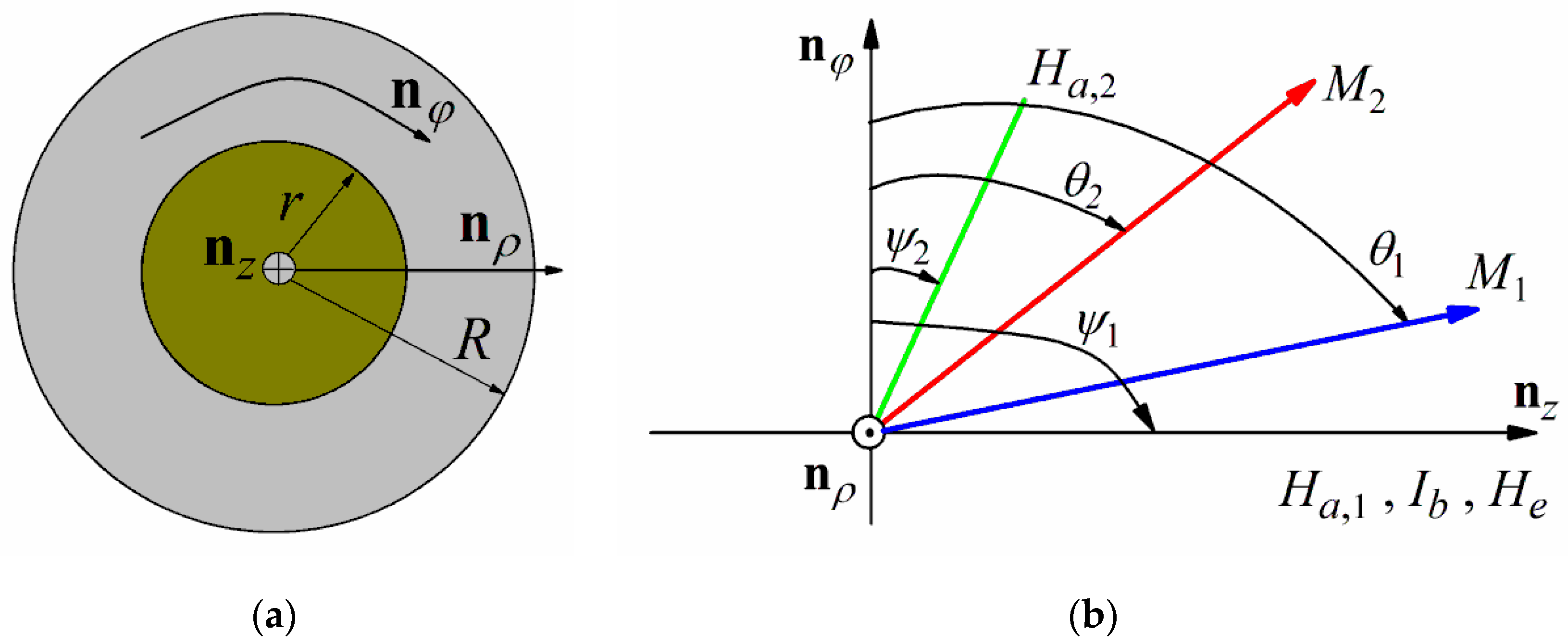
2.1. Static Magnetization Distribution

Following the approach developed previously in [19], let us assume that a glass-coated amorphous microwire with the diameter of metallic nucleus 2R consists of two regions with different types of magnetic anisotropy. In the inner region (core) with the diameter 2r, the anisotropy is axial, and the outer region (shell) has a helical anisotropy induced after stress-annealing. The microwire is subjected to the alternating current I(t) = I0exp(–iωt) (here t is the time, ω is the angular frequency and i is the imaginary unit) and to the direct bias current Ib, and the external magnetic field He is parallel to the microwire axis. The tensile stress σt and uniform torsional stress with the angular displacement per unit length τ are applied to the microwire. The microwire cross-section and a sketch of the coordinate system used for analysis are shown in Figure 1. Since all fields lie within the φz plane, the magnetization vector is limited to the same plane.
Further, we assume that the magnetization is uniform within two regions of the microwire, and the exchange and magnetostatic coupling between the regions can be neglected [19]. Note that it was demonstrated that account of the exchange coupling between the core and shell regions can improve an agreement between theory and experiment for the GMI response in amorphous wires [34]. As a matter of principle, the coupling can be taken into account by introducing the effective interaction field between the core and shell [32,34]. However, in this case, the model becomes more complicated. In this regard, to simplify the model we neglect the coupling between the core and shell regions of the microwire.
The static equilibrium magnetization distribution within the core and shell can be obtained by the minimization of the free energy. The free energy density U can be presented as a sum of the intrinsic magnetic anisotropy term, Zeeman energy, and magnetoelastic anisotropy energy induced by the external stresses:
U = ( M H a , j / 2 ) sin 2 ( θ j ψ j ) M H e sin θ j + U b + U ten + U tor .
Here and hereafter the subscript j = 1 and j = 2 corresponds to the core and shell region, respectively; M is the saturation magnetization; Ha,j is the intrinsic magnetic anisotropy fields in the core and shell; θj and ψj are the equilibrium magnetization angles and the anisotropy axis angles with respect to the azimuthal direction (ψ1 = π/2 for the core region); Ub is the Zeeman energy of the field of the bias current; Uten and Utor are the magnetoelastic anisotropy energies induced by the tensile and torsional stresses.
The term Ub can be written as follows
U b = 2 M I b ρ cos θ j / c R 2 ,
where ρ is the radial coordinate and c is the speed of light in a vacuum.
The magnetoelastic anisotropy energy Uten induced by the tensile stress has the following form [1]:
U ten = ( 3 / 2 ) λ s σ t cos 2 θ j ,
where λs > 0 is the magnetostriction coefficient.
The torsional stress results in the appearance of the helical magnetoelastic anisotropy in the microwire, with the easy magnetization axis being the angle of π/4 with azimuthal direction. The magnetoelastic anisotropy energy Utor can be expressed as [1]
U tor = ( 3 / 2 ) λ s G τ ρ sin 2 ( θ j π / 4 ) ,
where G is the shear modulus.
It follows from Equations (2) and (4) that the Zeeman energy Ub of the bias field and the magnetoelastic anisotropy Utor due to the torsional stress varies over the microwire cross-section. To simplify the model, we assume further that the contributions of these terms to the free energy density corresponding to the maximal values for the core (at ρ = r) and shell (at ρ = R) regions.
Then, the minimization of the free energy density results in the following equations for the equilibrium magnetization angles θj in the core and shell:
H a , j sin ( θ j ψ j ) cos ( θ j ψ j ) H e cos θ j + H b , j sin θ j ( H ten / 2 ) sin 2 θ j ( H tor , j / 2 ) cos 2 θ j = 0   .
Here we introduce the fields
H b , 1 = 2 I b r / c R 2 ,
H b , 2 = 2 I b / c R ,
H ten = 3 λ s σ t / M ,
H tor , 1 = 3 λ s G τ r / M ,
H tor , 2 = 3 λ s G τ R / M .
Note that the general approach to describe the Ub and Utor energy terms consists of the integration of the free energy density over the radial coordinate and the following minimization of the resulting energy. Since both the Ub and Utor terms depend linearly on the radial coordinate, the minimization procedure leads to Equation (2) for the equilibrium magnetization angles, and the only difference is in the numerical coefficients in Equations (6), (7), (9) and (10). Thus, the simplified model described above gives the same basic predictions as compared to the general approach. In addition, the assumption that the contributions of the Ub and Utor terms correspond to their maximal values in both regions allows one to describe the conditions for the fields at the surface of the metallic nucleus of the microwire.
It follows from Equation (5) that the magnetoelastic anisotropy interacts with the intrinsic magnetic anisotropy and changes the equilibrium magnetization angles θj. Equation (5) can be rewritten in the following form with effective uniaxial anisotropy:
H eff , j sin ( θ j α j ) cos ( θ j α j ) H e cos θ j + H b , j sin θ j = 0 .
Here Heff,j and αj are the effective anisotropy fields and anisotropy angles, correspondingly. After simple mathematical transformations, for αj and Heff,j we obtain [31]:
tan 2 α j = H a , j sin 2 ψ j + H tor , j H a , j cos 2 ψ j H ten ,
H eff , j = H a , j cos 2 ψ j H ten cos 2 α j .
Let us discuss the changes in the effective anisotropy fields and angles in the presence of external stresses. The application of the tensile stress σt (at τ = 0) increases the axial effective anisotropy field Heff,1 in the core region. It follows from Equations (12) and (13) that for the shell region, the growth of σt leads to a deviation of the effective anisotropy angle α2 from the azimuthal direction and a decrease of the effective anisotropy field Heff,2. Note that these dependencies are opposite to the behavior of the effective anisotropy in Co-rich amorphous microwires with slightly negative magnetostriction. It is well-known that in Co-rich microwires, the effective anisotropy axis rotates toward the azimuthal direction with a growth of the tensile stress, and the effective anisotropy field increases [1,30,31,32].
When the torsional stress is applied to the microwire (at σt = 0), the angle α1 in the core region changes within the range from 3π/4 at the high negative direction of the stress (counter-clockwise rotation) to π/4 at high positive stress (clockwise rotation). The effective anisotropy field Heff,1 increases monotonically with the stress. Figure 2 illustrates the influence of the torsional stress on the effective anisotropy angle α2 and the effective anisotropy field Heff,2 in the shell region. The angle α2 increases from −π/4 to π/4 with the field Htor,2. The effective anisotropy in the shell becomes circular (α2 = 0), when Htor,2 = −Ha,2sin2ψ2. The dependence of the effective anisotropy field Heff,2 on the field Htor,2 has a minimum (see Figure 2b). The minimum attains at α2 = 0, and the minimal value of the effective anisotropy field is equal to Ha,2cos2ψ2.

2.2. Impedance Tensor

The GMI effect can be described in terms of the surface impedance tensor [35]. The longitudinal Zzz and off-diagonal Zφz impedance components can be presented as follows [36]:
Z z z = ( 2 l / c R ) ( ζ m   sin 2   θ 2 + ζ 0   cos 2   θ 2 ) ,
Z ϕ z = ( 4 π N / c ) ( ζ m ζ 0 ) sin θ 2 cos θ 2 .
Here l is the microwire length, N is the number of turns in the pick-up coil, ζm and ζ0 are the magnetic and non-magnetic components of the surface impedance tensor and the equilibrium magnetization angle θ2 in the shell is given by Equation (11).
The surface impedance tensor components ζm and ζ0 depend on the magnetic structure of the microwire. The expressions for ζm and ζ0 for the microwire with the core–shell magnetic structure were obtained in [19] assuming that the magnetization in the core region is directed along the microwire axis (θ1 = ±π/2). However, in the presence of the bias current or the torsional stress, the equilibrium magnetization angle θ1 deviates from the longitudinal direction (see Equation (5)). Taking into account the deviation of θ1, the surface impedance component ζm can be expressed as
ζ m = c k 2 4 π σ × J 0 ( k 2 R ) + P m Y 0 ( k 2 R ) J 1 ( k 2 R ) + P m Y 1 ( k 2 R ) .
Here Jn and Yn (n = 0, 1) are the Bessel functions of the first and the second kind, respectively; k22 = k02μ2, k02 = 2i/δ2, δ = c/(2πσω)1/2, σ is the microwire conductivity, μ2 is the transverse permeability in the shell region and the parameter Pm is given by
P m = ( k 2 / k 1 ) J 0 ( k 2 r ) Q J 1 ( k 2 r ) Q Y 1 ( k 2 r ) ( k 2 / k 1 ) Y 0 ( k 2 r ) ,
where k12 = k02μ1, μ1 is the transverse permeability in the core region and
Q = J 0 ( k 1 r ) J 1 ( k 1 r ) sin 2 θ 1 + J 0 ( k 0 r ) J 1 ( k 0 r ) cos 2 θ 1 .
Note that at θ1 = ±π/2 from Equation (18) we have Q = J0(k1r)/J1(k1r), and Equations (16)–(18) transform to expressions obtained in [19]. The non-magnetic component ζ0 can be obtained from Equations (16) and (17) assuming that μ2 = 1 [36]. Thus, for ζ0 we have
ζ 0 = c k 0 4 π σ × J 0 ( k 0 R ) + P 0 Y 0 ( k 0 R ) J 1 ( k 0 R ) + P 0 Y 1 ( k 0 R ) ,
P 0 = ( k 0 / k 1 ) J 0 ( k 0 r ) Q J 1 ( k 0 r ) Q Y 1 ( k 0 r ) ( k 0 / k 1 ) Y 0 ( k 0 r ) .
As follows from Equations (16)–(20) the longitudinal Zzz and off-diagonal Zφz impedance components are governed by the values of the transverse permeability μj in the core and shell regions. The transverse permeability can be found from a solution of the linearized Landau–Lifshitz–Gilbert equation. Taking into account the effects of the bias current and external stresses, we can present the values of μj in the following form [1,21]:
μ j = ω m 2 ( ω m + ω j ) ω j ω 2 i κ ω m ω .
Here ωm = γ4πM, γ is the gyromagnetic constant, κ is the Gilbert damping parameter and
ω j = γ [ H eff , j cos 2 ( θ j α j ) + H e sin θ j + H b , j cos θ j ] , ω j = γ [ H eff , j cos 2 ( θ j α j ) + H e sin θ j + H b , j cos θ j ] .
The procedure of the calculation of the GMI response in the microwire with the core–shell magnetic structure can be summarized as follows. The equilibrium magnetization angles θj in the core and shell regions can be found from a solution of Equation (11) taking into account expressions (12) and (13). The values of the transverse permeability μj in the core and shell regions are given by Equations (21) and (22). After that, the corresponding values of k1 and k2 can be calculated, and the impedance components Zzz and Zφz are obtained by means of Equations (14)–(20).
In conclusion of this section, it should be noted that both the magnetization rotation and domain-walls motion contribute to the permeability and magnetoimpedance response. In this work, we analyze the ODMI at sufficiently high frequencies, when the domain-walls motion is strongly damped [1], and the values of the transverse permeability in the core and shell regions are governed by the magnetization rotation only. It has been found that in soft magnetic amorphous materials exhibiting the GMI effect, the domain-walls motion is negligible in the frequency range from several hundred kHz to a few MHz [37,38,39]. At low frequencies, the contribution of motion of the domain wall between the core and shell to the ODMI response should be taken into account.

3. Results

3.1. Asymmetric Off-Diagonal Magnetoimpedance

At first, we consider the influence of the bias current on the ODMI in annealed Fe-rich amorphous microwire without external stresses. Note that the field dependence of the ODMI response Zφz = RφziXφz (here Rφz and Xφz are the real and imaginary parts of the ODMI) was described previously for a microwire with the core–shell structure assuming that the magnetization in the core region has the longitudinal direction [19]. To obtain the ODMI effect with high field sensitivity, the domain structure in the shell region should be removed. The threshold field Hth of the bias current to eliminate the surface domain structure can be expressed as follows [21,40]: Hth = Ha,2|sinψ2|. Taking into account Equation (7), we find for the threshold bias current Ith:
I th = ( c R H a , 2 / 2 ) | sin ψ 2 | .
Assuming for estimations that 2R = 15 μm, ψ2 = −0.05π and Ha,2 = 30 Oe, we find for the value of the threshold bias current Ith ≅ 17.5 mA.
Shown in Figure 3 are the field dependences of the real Rφz and imaginary parts Xφz of the ODMI calculated for different values of Ib > Ith. For convenience, the values of Rφz and Xφz are reduced to the characteristic off-diagonal impedance Z0:
Z 0 = 2 π N R Z DC / l = 2 N / σ R ,
where ZDC = l/πσR2 is the resistance in the direct current mode. Assuming that N = 50, 2R = 15 μm and σ = 5 × 10¹⁵ s−1, we obtain Z0 ≅ 24 Ohm.
At Ib > Ith, the asymmetry in the field dependence of the ODMI appears The asymmetry arises due to the interaction of the helical anisotropy with the circular magnetic field induced by the bias current [1,21,40]. The real and imaginary parts of the ODMI increase sharply at IbIth. With a further increase of the bias current, the field sensitivities of Rφz and Xφz decrease due to a drop in the transverse permeability in the shell region, however, they remain sufficiently high within a wide range of the bias current.
Although the shell region with a helical anisotropy makes the main contribution to the ODMI of the microwire, the ODMI is very sensitive to the volume part of the core region. Figure 4 illustrates the effect of the core region diameter 2r on the ODMI. The dependences of Rφz and Xφz on the external field have similar behavior for all values of 2r, and the decrease of the core diameter results in a growth of the ODMI response. Note that the volume parts of the core and shell can be tuned by stress-annealing. In particular, an increase in the annealing temperature and time [12] and tensile stress during the annealing [14,41,42] leads to a decrease in the core region volume.
It follows from Figure 3 and Figure 4 that the field dependences of the real and imaginary parts of the ODMI response show nearly linear behavior at He ≅ −Ha,2sin2ψ2, where the ODMI turns to zero. To analyze the frequency dependences of Rφz and Xφz, let us introduce the field sensitivities of the real SR and imaginary SX parts of the ODMI defined as follows [43]:
S R = R p / Δ H ,
S X = | X p | / Δ H .
Here Rp and |Xp|are the maximum values of Rφz and |Xφz| at positive external fields, ΔH = Hp + Ha,2sin2ψ2 and Hp is the external field at the peak.
The frequency dependences of the field sensitivities SR and SX calculated for different values of the bias current are presented in Figure 5. The values of SR and SX have different frequency behavior. The field sensitivity SR of the real part of the ODMI increases monotonically with the frequency, whereas SX has a maximum at a certain frequency. At low frequencies, the field sensitivity SX is higher than SR. It also follows from Figure 5 that field sensitivities decrease with a growth of the bias current Ib. However, the magnitudes of SR and SX are relatively high within a wide range of the bias current.
Note that the obtained field dependences of the ODMI in the presence of the bias current describe qualitative results of the experimental studies of the OMDI effect in stress-annealed Fe-rich microwires [11,12,13]. The origin of the strong ODMI is related to a helical anisotropy in the shell region of the microwire, which appears after the annealing. Although the main contribution to the ODMI comes from the shell, the core region affects the ODMI through its volume and a deviation of the magnetization from the longitudinal direction in the inner part of the microwire.

3.2. Effect of Tensile Stress on Off-Diagonal Magnetoimpedance

The application of the tensile stress to the microwire results in changes in the equilibrium magnetization distribution and consequently affects the ODMI response. Figure 6 shows the field dependences of Rφz and Xφz calculated for different values of the tensile stress σt. Both the real and imaginary parts of the ODMI exhibit similar behavior with an increase in stress. The peaks in Rφz and Xφz become more pronounced, and the peak fields shift towards zero fields. It follows from Figure 6 also that the field sensitivity of the ODMI increases with the tensile stress.
The evolution of the ODMI response in the presence of tensile stress is related to the changes in the effective anisotropy in the microwire shell region. With an increase of the tensile stress, the effective anisotropy angle α2 in the shell deviates from the azimuthal direction, and the effective anisotropy field Heff,2 decreases (see Equations (12) and (13)). Taking into account the changes in α2 and Heff,2 under the effect of the tensile stress, we can present the expression for threshold field Hth of the bias current to eliminate domain structure in the shell region in the following form: Hth = Heff,2|sinα2|. Correspondingly, the expression for the threshold bias current Ith can be rewritten as
I th = ( c R H eff , 2 / 2 ) | sin α 2 | .
It follows from Equations (12), (13), and (27) that the threshold current increases with the tensile stress. Hence, the threshold current Ith tends to the bias current Ib under the application of the tensile stress. As discussed above, the ODMI increases when the bias current is close to Ith (see Figure 3). Thus, an increase of the tensile stress σt results in a growth of the ODMI response (see Figure 6).
The frequency dependences of the field sensitivities SR and SX for different values of the tensile stress σt are shown in Figure 7. The values of SR and SX are calculated by means of Equations (25) and (26) taking into account that ΔH = Hp + Heff,2sin2α2. The field sensitivities increase monotonically with the value of the applied stress (see Figure 7).
To describe the ODMI sensitivity to the tensile stress σt we introduce the ratios
( Δ R / R φ z ) σ = [ R φ z ( σ t ) R φ z ( 0 ) ] / R φ z ( 0 ) ,
( Δ X / R φ z ) σ = [ X φ z ( σ t ) X φ z ( 0 ) ] / X φ z ( 0 ) ,
where Rφz(0) and Xφz(0) are the real and imaginary parts of the ODMI without tensile stress.
The frequency dependences of (ΔR/Rφz)σ and (ΔX/Xφz)σ calculated for a fixed external field He < Hp at f = 100 MHz for different values of the bias current are shown in Figure 8. Both the ratios of (ΔR/Rφz)σ and (ΔX/Xφz)σ have high sensitivity to the applied tension stress. As follows from Figure 8, the ratios of (ΔR/Rφz)σ and (ΔX/Xφz)σ exhibit nearly linear dependence on the tensile stress at low values of σt. This fact is attractive for the development of stress sensors.

3.3. Effect of Torsional Stress on Off-Diagonal Magnetoimpedance

The influence of the torsional stress on the ODMI response is more complicated. The application of the torsional stress to the microwire induces a helical anisotropy in the whole sample. Depending on the direction of the torsional stress, the anisotropy axis angle in the shell region can enhance or tend to zero (see Figure 2a). In addition, the torsional stress deviates slightly from the easy magnetization axis in the core region from the longitudinal direction.
The dependences of the real Rφz and imaginary parts Xφz of the ODMI on the external field are shown in Figure 9 at fixed Ib and different values of the angular displacement per unit length τ > 0. For low τ, the asymmetry between the absolute values of the peaks in Rφz and Xφz at positive and negative fields decreases. At some critical value of τ = τcr, the absolute values of the peaks become equal. At τ > τcr, the modulus of the peak in the real and imaginary parts of the ODMI at a negative external field becomes higher (see Figure 9). The critical value τcr of the angular displacement per unit length corresponds to the appearance of the effective circular anisotropy in the shell region (α2 = 0). It follows from Equation (12) that this condition satisfies when Htor,2 = –Ha,2sin2ψ2. Taking into account Equation (10), we obtain for τcr [44]:
τ cr = M H a , 2 sin 2 ψ 2 / 3 λ s G R .
For negative torsional stresses (τ < 0), the increase of the absolute value of τ leads to a growth of the effective anisotropy field Heff,2 and effective anisotropy angle modulus in the shell. As a result, the threshold bias current Ith increases (see Equation (27)). Correspondingly, the peaks in Rφz and Xφz at negative external field growth. The maximal field sensitivity of the ODMI is achieved when the bias current Ib tends to the threshold one Ith. With a further increase of the stress absolute value, the bias current becomes less than Ith, and the field dependences of Rφz and Xφz exhibit hysteretic behavior [44].
Figure 10 shows the frequency dependences of the field sensitivities of the real and imaginary parts of the ODMI calculated for different values of the angular displacement per unit length τ. At not-too-low frequencies, the field sensitivity SR of the real part of the ODMI is higher than SX. Both the sensitivities SR and SX decrease monotonically with an increase of the angular displacement per unit length τ.

4. Discussion

Fe-rich glass-coated amorphous microwires with positive magnetostriction are attractive for GMI applications due to higher saturation magnetization and lower price in comparison with Co-rich microwires. However, as-prepared Fe-rich microwires exhibit a low GMI effect. It was found that stress-annealing or Joule heating may enhance significantly the GMI in amorphous microwires with positive magnetostriction [8,17]. The improvement of the GMI effect is related to changes in the distribution of the residual stresses within Fe-rich microwire after annealing resulting in the appearance of circular or helical magnetic anisotropy at the microwire surface layer. Recently, an electrodynamic model was proposed to describe the GMI effect in stress-annealed amorphous microwires with positive magnetostriction [19]. The obtained theoretical dependences allowed one to explain the main results of experimental studies of the GMI in stress-annealed Fe-rich amorphous microwires. Using the anisotropy fields in the core Ha,1 and shell Ha,2, the anisotropy axis angle in the shell ψ2, and the core diameter 2r as fitting parameters, the calculated results explained the evolution of the field dependence of the GMI response with a frequency increase (the transition from the single-peak to two-peak behavior). In addition, the theoretical results described the positions of the peaks in the GMI field dependence and the magnitude of the GMI ratio.
In this work, we modify the model to analyze the effect of tensile and torsional stresses on the ODMI in annealed Fe-rich glass-coated amorphous microwires. The stress application changes the magnetization distribution in the microwire due to the interaction of the intrinsic magnetic anisotropy and the magnetoelastic anisotropy induced by external stress. The results of modeling show that the ODMI response in annealed Fe-rich microwire can be enhanced by tensile or torsional stress. It is demonstrated that the main contribution to the ODMI in the microwire comes from the surface region with a helical anisotropy. However, the central region of the microwire can influence the ODMI response through its volume and a deviation of the magnetization from the longitudinal direction.
It is well-known that the strong ODMI effect in amorphous microwires can be observed when the bias current is applied to the sample to remove a domain structure in the microwire surface region. However, high values of the bias current results in Joule heating. It can lead to crystallization and degradation of the soft magnetic properties of the microwire [7,12]. Correspondingly, there are some restrictions on the use of the ODMI effect in technological applications.
In this work, we analyze the ODMI effect in annealed Fe-rich amorphous microwires with positive magnetostiction. Note that the approach proposed allows one to describe also the influence of the tension and torsional stresses on the longitudinal GMI in microwires with the core–shell magnetic structure.
In conclusion of this section, it should be noted that there are no experimental studies of the ODMI in annealed amorphous microwires with positive magnetostriction in the presence of external stresses, and further verification of predictions of the proposed model is required. However, the effect of the external stresses on the ODMI seems to be promising for applications. The obtained results demonstrate that the field dependence of the ODMI is very sensitive to external stresses, and it may allow one to improve the sensitivity of the magnetic-field sensors.

5. Conclusions

The influence of the tensile and torsional stresses on the ODMI in annealed glass-coated amorphous microwires with positive magnetostrcition is analyzed by means of the core–shell magnetic structure. It is assumed that the microwire has an axial anisotropy in the inner core and a helical anisotropy in the external shell region, which occurs after the annealing. The effect of the applied stresses on the ODMI is related to the interaction of the microwire internal anisotropy and the magnetoelastic anisotropy induced by external stresses. The microwire impedance tensor is obtained taking into account the magnetoelastic anisotropy. It is demonstrated that the external stresses affect the ODMI response and may enhance the ODMI field sensitivity within a wide frequency range. The obtained results may be useful from the point of view of the development of the magnetic field and stress sensors.

Funding

This research received no external funding.

Institutional Review Board Statement

Not applicable.

Informed Consent Statement

Not applicable.

Data Availability Statement

The data that support the findings of this study are available from the author upon reasonable request.

Acknowledgments

The author would like to thank Serghei Baranov and Vyacheslav Popov for fruitful discussions.

Conflicts of Interest

The author declares no conflict of interest.

References

  1. Knobel, M.; Vázquez, M.; Kraus, L. Giant magnetoimpedance. In Handbook of Magnetic Materials; Buschow, K.H.J., Ed.; Elsevier: Amsterdam, The Netherlands, 2003; Volume 15, pp. 497–563. [Google Scholar]
  2. Phan, M.-H.; Peng, H.-X. Giant magnetoimpedance materials: Fundamentals and applications. Prog. Mater. Sci. 2008, 53, 323–420. [Google Scholar] [CrossRef]
  3. Zhukov, A.; Ipatov, M.; Zhukova, V. Advances in giant magnetoimpedance of materials. In Handbook of Magnetic Materials; Buschow, K.H.J., Ed.; Elsevier: Amsterdam, The Netherlands, 2015; Volume 24, pp. 139–236. [Google Scholar]
  4. Vázquez, M. Advanced magnetic microwires. In Handbook of Magnetism and Advanced Magnetic Materials; Kronműller, H., Parkin, S.S.P., Eds.; Wiley: Chichester, UK, 2007; pp. 2193–2226. [Google Scholar]
  5. Zhukov, A.; Zhukova, V. Magnetic Properties and Applications of Ferromagnetic Microwires with Amorphous and Nanocrystalline Structure; Nova Science Publishers: New York, NY, USA, 2009. [Google Scholar]
  6. Baranov, S.A.; Larin, V.S.; Torcunov, A.V. Technology, preparation and properties of the cast glass-coated magnetic microwires. Crystals 2017, 7, 136. [Google Scholar] [CrossRef]
  7. Zhukov, A.; Ipatov, M.; Churyukanova, M.; Talaat, A.; Blanco, J.M.; Zhukova, V. Trends in optimization of giant magnetoimpedance effect in amorphous and nanocrystalline materials. J. Alloys Compd. 2017, 727, 887–901. [Google Scholar] [CrossRef]
  8. Zhukova, V.; Corte-Leon, P.; Blanco, J.M.; Ipatov, M.; Gonzalez-Legarreta, L.; Gonzalez, A.; Zhukov, A. Development of magnetically soft amorphous microwires for technological applications. Chemosensors 2022, 10, 26. [Google Scholar] [CrossRef]
  9. Chiriac, H.; Óvári, T.A. Amorphous glass-covered magnetic wires: Preparation, properties, applications. Prog. Mater. Sci. 1996, 40, 333–407. [Google Scholar] [CrossRef]
  10. Zhukova, V.; Ipatov, M.; Talaat, A.; Blanco, J.M.; Churyukanova, M.; Zhukov, A. Effect of stress annealing on magnetic properties and GMI effect of Co- and Fe-rich microwires. J. Alloys Compd. 2017, 707, 189–194. [Google Scholar] [CrossRef]
  11. Zhukova, V.; Blanco, J.M.; Ipatov, M.; Gonzalez, J.; Churyukanova, M.; Zhukov, A. Engineering of magnetic softness and giant magnetoimpedance effect in Fe-rich microwires by stress-annealing. Scr. Mater. 2018, 142, 10–14. [Google Scholar] [CrossRef]
  12. Zhukova, V.; Blanco, J.M.; Ipatov, M.; Churyukanova, M.; Taskaev, S.; Zhukov, A. Tailoring of magnetoimpedance effect and magnetic softness of Fe-rich glass-coated microwires by stress-annealing. Sci. Rep. 2018, 8, 3202. [Google Scholar] [CrossRef]
  13. Zhukova, V.; Blanco, J.M.; Ipatov, M.; Churyukanova, M.; Olivera, J.; Taskaev, S.; Zhukov, A. Optimization of high frequency magnetoimpedance effect of Fe-rich microwires by stress-annealing. Intermetallics 2018, 94, 92–98. [Google Scholar] [CrossRef]
  14. Corte-Leon, P.; Zhukova, V.; Blanco, J.M.; Gonzalez-Legarreta, L.; Ipatov, M.; Zhukov, A. Stress-induced magnetic anisotropy enabling engineering of magnetic softness of Fe-rich amorphous microwires. J. Magn. Magn. Mater. 2020, 510, 166939. [Google Scholar] [CrossRef]
  15. Gonzalez, A.; Zhukova, V.; Ipatov, M.; Corte-Leon, P.; Blanco, J.M.; Zhukov, A. Effect of Joule heating on GMI and magnetic properties of Fe-rich glass-coated microwires. AIP Adv. 2022, 12, 035021. [Google Scholar] [CrossRef]
  16. Gonzalez, A.; Zhukova, V.; Corte-Leon, P.; Chizhik, A.; Ipatov, M.; Blanco, J.M.; Zhukov, A. Tuning of magnetoimpedance effect and magnetic properties of Fe-rich glass-coated microwires by Joule heating. Sensors 2022, 22, 1053. [Google Scholar] [CrossRef]
  17. Zhukov, A.; Corte-Leon, P.; Gonzalez-Legarreta, L.; Ipatov, M.; Blanco, J.M.; Gonzalez, A.; Zhukova, V. Advanced functional magnetic microwires for technological applications. J. Phys. D Appl. Phys. 2022, 55, 253003. [Google Scholar] [CrossRef]
  18. Baranov, S.A. Dependence of the magnetic properties of micro- and nanowires from stress and magnetic heat treatment. Surf. Eng. Appl. Electrochem. 2017, 53, 77–88. [Google Scholar] [CrossRef]
  19. Buznikov, N.A.; Popov, V.V. A core–shell model for magnetoimpedance in stress-annealed Fe-rich amorphous microwires. J. Supercond. Nov. Magn. 2021, 34, 169–177. [Google Scholar] [CrossRef]
  20. Antonov, A.; Iakubov, I.; Lagarkov, A. Longitudinal-transverse linear transformation of the HF-current in soft magnetic materials with induced anisotropy. IEEE Trans. Magn. 1997, 33, 3367–3369. [Google Scholar] [CrossRef]
  21. Makhnovskiy, D.P.; Panina, L.V.; Mapps, D.J. Field-dependent surface impedance tensor in amorphous wires with two types of magnetic anisotropy: Helical and circumferential. Phys. Rev. B 2001, 63, 144424. [Google Scholar] [CrossRef]
  22. Sandacci, S.; Makhnovskiy, D.; Panina, L.; Mohri, K.; Honkura, Y. Off-diagonal impedance in amorphous wires and its application to linear magnetic sensors. IEEE Trans. Magn. 2004, 40, 3505–3511. [Google Scholar] [CrossRef]
  23. Ipatov, M.; Chizhik, A.; Zhukova, V.; Gonzalez, J.; Zhukov, A. Correlation of surface domain structure and magneto-impedance in amorphous microwires. J. Appl. Phys. 2011, 109, 113924. [Google Scholar] [CrossRef]
  24. Dufay, B.; Saez, S.; Dolabdjian, C.; Yelon, A.; Ménard, D. Impact of electronic conditioning on the noise performance of a two-port network giant magnetoimpedance magnetometer. IEEE Sens. J. 2011, 11, 1317–1324. [Google Scholar] [CrossRef] [Green Version]
  25. Portalier, E.; Dufay, B.; Dolabdjian, C.; Seddaoui, D.; Yelon, A.; Ménard, D. Study of the low-frequency excess equivalent magnetic noise in GMI-based devices. IEEE Sens. J. 2017, 17, 6888–6894. [Google Scholar] [CrossRef]
  26. Shen, L.P.; Uchiyama, T.; Mohri, K.; Kita, E.; Bushida, K. Sensitive stress-impedance micro sensor using amorphous magnetostrictive wire. IEEE Trans. Magn. 1997, 33, 3355–3357. [Google Scholar] [CrossRef]
  27. Mohri, K.; Uchiyama, T.; Shen, L.P.; Cai, C.M.; Panina, L.V. Sensitive micro magnetic sensor family utilizing magneto- impedance (MI) and stress-impedance (SI) effects for intelligent measurements and controls. Sens. Actuators A 2001, 91, 85–90. [Google Scholar] [CrossRef]
  28. Bayri, N.; Atalay, S. Giant stress-impedance effect in Fe71Cr7Si9B13 amorphous wires. J. Alloys Compd. 2004, 381, 245–249. [Google Scholar] [CrossRef]
  29. Zhukov, A. Glass-coated magnetic microwires for technical applications. J. Magn. Magn. Mater. 2002, 242–245, 216–233. [Google Scholar] [CrossRef]
  30. Zhukov, A.; Zhukova, V.; Blanco, J.M.; González, J. Recent research on magnetic properties of glass-coated microwires. J. Magn. Magn. Mater. 2005, 294, 182–192. [Google Scholar] [CrossRef]
  31. Sandacci, S.; Makhnovskiy, D.; Panina, L.; Larin, V. Stress-dependent magnetoimpedance in Co-based amorphous wires with induced axial anisotropy for tunable microwave composites. IEEE Trans. Magn. 2005, 41, 3553–3555. [Google Scholar] [CrossRef]
  32. Popov, V.V.; Berzhansky, V.N.; Gomonay, H.V.; Qin, F.X. Stress-induced magnetic hysteresis in amorphous microwires probed by microwave giant magnetoimpedance measurements. J. Appl. Phys. 2013, 113, 17A326. [Google Scholar] [CrossRef]
  33. Zhukov, A.; Ipatov, M.; Churyukanova, M.; Kaloshkin, S.; Zhukova, V. Giant magnetoimpedance in thin amorphous wires: From manipulation of magnetic field dependence to industrial applications. J. Alloys Compd. 2014, 586, S279–S286. [Google Scholar] [CrossRef]
  34. Melo, L.G.C.; Ménard, D.; Ciureanu, P.; Yelon, A.; Cochrane, R.W. Coupled core–shell model of magnetoimpedance in wires. J. Appl. Phys. 2004, 95, 1331–1335. [Google Scholar] [CrossRef]
  35. Landau, L.D.; Lifshitz, E.M. Electrodynamics of Continuous Media; Pergamon: London, UK, 1975. [Google Scholar]
  36. Ménard, D.; Yelon, A. Theory of longitudinal magnetoimpedance in wires. J. Appl. Phys. 2000, 88, 379–393. [Google Scholar] [CrossRef]
  37. Panina, L.V.; Mohri, K.; Uchiyama, T.; Noda, M.; Bushida, K. Giant magneto-impedance in Co-rich amorphous wires and films. IEEE Trans. Magn. 1995, 31, 1249–1260. [Google Scholar] [CrossRef]
  38. Melo, L.G.C.; Santos, A.D. Domain wall oscillations in GMI configuration. Mater. Sci. Forum 1999, 302–303, 219–223. [Google Scholar] [CrossRef]
  39. Kraus, L. GMI modeling and material optimization. Sens. Actuators A 2003, 106, 187–194. [Google Scholar] [CrossRef]
  40. Panina, L.V.; Mohri, K.; Makhnovskiy, D.P. Mechanism of asymmetrical magnetoimpedance in amorphous wires. J. Appl. Phys. 1999, 85, 5444–5446. [Google Scholar] [CrossRef]
  41. Zhukova, V.; Corte-Leon, P.; Ipatov, M.; Blanco, J.M.; Gonzalez-Legarreta, L.; Zhukov, A. Development of magnetic microwires for magnetic sensor applications. Sensors 2019, 19, 4767. [Google Scholar] [CrossRef]
  42. Zhukov, A.; Ipatov, M.; Corte-Leon, P.; Gonzalez-Legarreta, L.; Blanco, J.M.; Zhukova, V. Soft magnetic microwires for sensor applications. J. Magn. Magn. Mater. 2020, 498, 166180. [Google Scholar] [CrossRef]
  43. Buznikov, N.A. Influence of bias current on off-diagonal magnetoimpedance in composite wires. J. Supercond. Nov. Magn. 2018, 31, 4039–4045. [Google Scholar] [CrossRef]
  44. Buznikov, N.A.; Antonov, A.S.; Granovsky, A.B. Asymmetric magnetoimpedance in amorphous microwires due to bias current: Effect of torsional stress. J. Magn. Magn. Mater. 2014, 355, 289–294. [Google Scholar] [CrossRef]
Figure 1. (a) The microwire cross-section and unit vectors nρ, nφ and nz of the coordinate system used for analysis. (b) A sketch of the angles in the model lying within the nφnz plane.
Magnetism 03 00005 g001
Figure 2. (a) The effective anisotropy angle α2 and (b) the effective anisotropy field Heff,2 in the shell region as a function of the field Htor,2 at different values of the intrinsic anisotropy axis angle ψ2.
Magnetism 03 00005 g002
Figure 3. (a) The real part Rφz and (b) the imaginary part Xφz of the ODMI as a function of the external field He at f = ω/2π = 100 MHz for different values of the bias current Ib. Parameters used for calculations are 2R = 15 μm, 2r = 8 μm, M = 900 G, σ = 5 × 10¹⁵ s−1, κ = 0.15, Ha,1 = 5 Oe, Ha,2 = 30 Oe and ψ2 = −0.05π.
Magnetism 03 00005 g003
Figure 4. (a) The real part Rφz and (b) the imaginary part Xφz of the ODMI as a function of the external field He at f = 100 MHz and Ib = 30 mA for different values of the core region diameter 2r. Other parameters used for calculations are the same as in Figure 3.
Magnetism 03 00005 g004
Figure 5. The field sensitivity of the real part SR (a) and imaginary part SX (b) of the ODMI as a function of the frequency f for different values of the bias current Ib. Other parameters used for calculations are the same as in Figure 3. The values of SR and SX are reduced to the characteristic field sensitivity S0 = Z0/Ha,2.
Magnetism 03 00005 g005
Figure 6. (a) The real part Rφz and (b) the imaginary part Xφz of the ODMI as a function of the external field He at f = 100 MHz and Ib = 30 mA for different values of the tensile stress σt. Magnetostriction coefficient λs = 40 × 10−6, other parameters used for calculations are the same as in Figure 3.
Magnetism 03 00005 g006
Figure 7. The field sensitivity of the real part SR (a) and imaginary part SX (b) of the ODMI as a function of the frequency f at Ib = 30 mA for different values of the tensile stress σt. Magnetostriction coefficient λs = 40 × 10−6, other parameters used for calculations are the same as in Figure 3.
Magnetism 03 00005 g007
Figure 8. The ratio of (ΔR/Rφz)σ (a) and (ΔX/Xφz)σ (b) as a function of the tensile stress σt at He = 10 Oe and f = 100 MHz for different values of the bias current Ib. Magnetostriction coefficient λs = 40 × 10−6, other parameters used for calculations are the same as in Figure 3.
Magnetism 03 00005 g008
Figure 9. (a) The real part Rφz and (b) the imaginary part Xφz of the ODMI as a function of the external field He at f = 100 MHz and Ib = 30 mA for different values of the angular displacement per unit length τ. Magnetostriction coefficient λs = 40 × 10−6, shear modulus G = 50 GPa, other parameters used for calculations are the same as in Figure 3.
Magnetism 03 00005 g009
Figure 10. The field sensitivity of the real part SR (a) and imaginary part SX (b) of the ODMI as a function of the frequency f at Ib = 30 mA for different values of the angular displacement per unit length τ. Magnetostriction coefficient λs = 40 × 10−6, shear modulus G = 50 GPa, other parameters used for calculations are the same as in Figure 3.
Magnetism 03 00005 g010
Disclaimer/Publisher’s Note: The statements, opinions and data contained in all publications are solely those of the individual author(s) and contributor(s) and not of MDPI and/or the editor(s). MDPI and/or the editor(s) disclaim responsibility for any injury to people or property resulting from any ideas, methods, instructions or products referred to in the content.

