

Practical Study of Mixed-Core High Frequency Power Transformer
Research and Development, M/S. Electronics Devices Worldwide Pvt. Ltd., 22 Mistry Industrial Estate, Cross Road A, Andheri East, Mumbai 400093, India
Magnetism 2022, 2(3), 306-327; https://doi.org/10.3390/magnetism2030022
Submission received: 13 May 2022
/
Revised: 15 August 2022
/
Accepted: 19 August 2022
/
Published: 1 September 2022
(This article belongs to the Special Issue Mathematical Modelling and Physical Applications of Magnetic Systems)
Abstract
:The design of medium- to high-frequency power electronics transformer aims not only to minimize the power loss in the windings and the core, but its heat removal features should also allow optimal use of both core and copper. The heat removal feature (e.g., thermal conduction) of a transformer is complex because there exist multiple loss centers. The bulk of total power loss is concentrated around a small segment of the core assembly where windings are overlaid. The primary winding is most constrained thermally. For superior use of core and copper, the temperature rise in different segments of the transformer should be well below their respective safe operating limits. In practice, cores of same soft-magnetic materials are traditionally used. To achieve superior temperature profile and for better long-term performance, this article proposes to use the mixed-core configuration. The new core(s) would replace the parent ones from the segment where windings are laid. The characteristic features of new cores would share increased burden of heat removal from the transformer. To obtain the qualitative insight of magnetic and thermal performance, the proposed mixed-core transformer would be thoroughly validated practically in two different high-power applications. In the first case, the core is always energized to its rated value, and in the second one, windings are always energized at respective rated current capacity.
1. Introduction
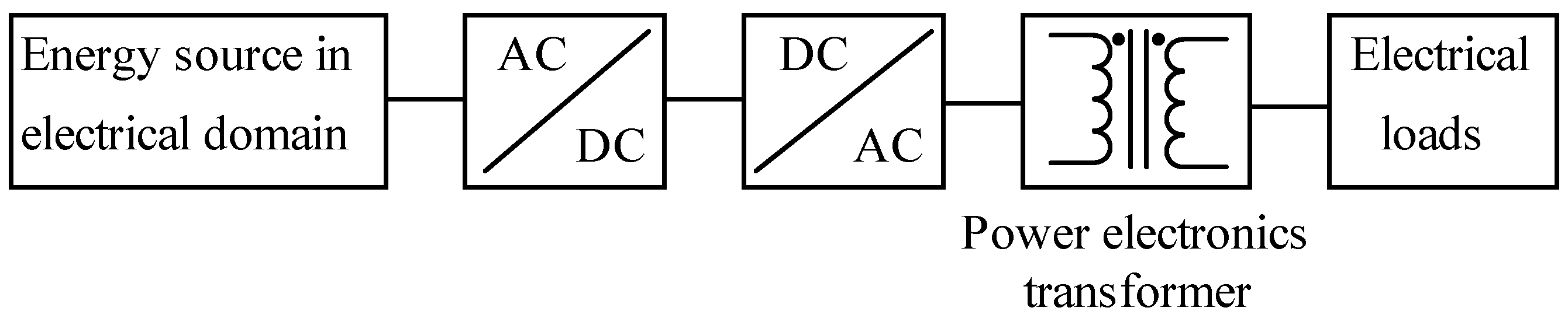
Power electronics converters [1] are used to ensure efficient handling of electrical energy where, as shown in Figure 1, power electronic transformer (PET) is an integral part [2,3,4,5,6,7]. Though it is a passive component, its role in power converters is immense. Apart from mandatory safety isolation, a PET could be used either for voltage [8] or current multiplication [4] to match the load characteristics of applications. Depending upon the topology of power converter used, additionally, it is often used to perform certain assisting roles in different soft-switched inverter operations [9,10,11]. The PET is used for instantaneous power transfer, and it should be efficient and compact. Due to the availability of a wide range of soft magnetic materials [12,13] in different geometries as well as of copper conductors (litz wires and copper foils) [14], the process of design optimization of a PET is now elaborate. For optimal design of a PET, the following aspects need to be looked into:
- The influence of soft magnetic materials of suitable geometry [13] as well as that of copper conductors.
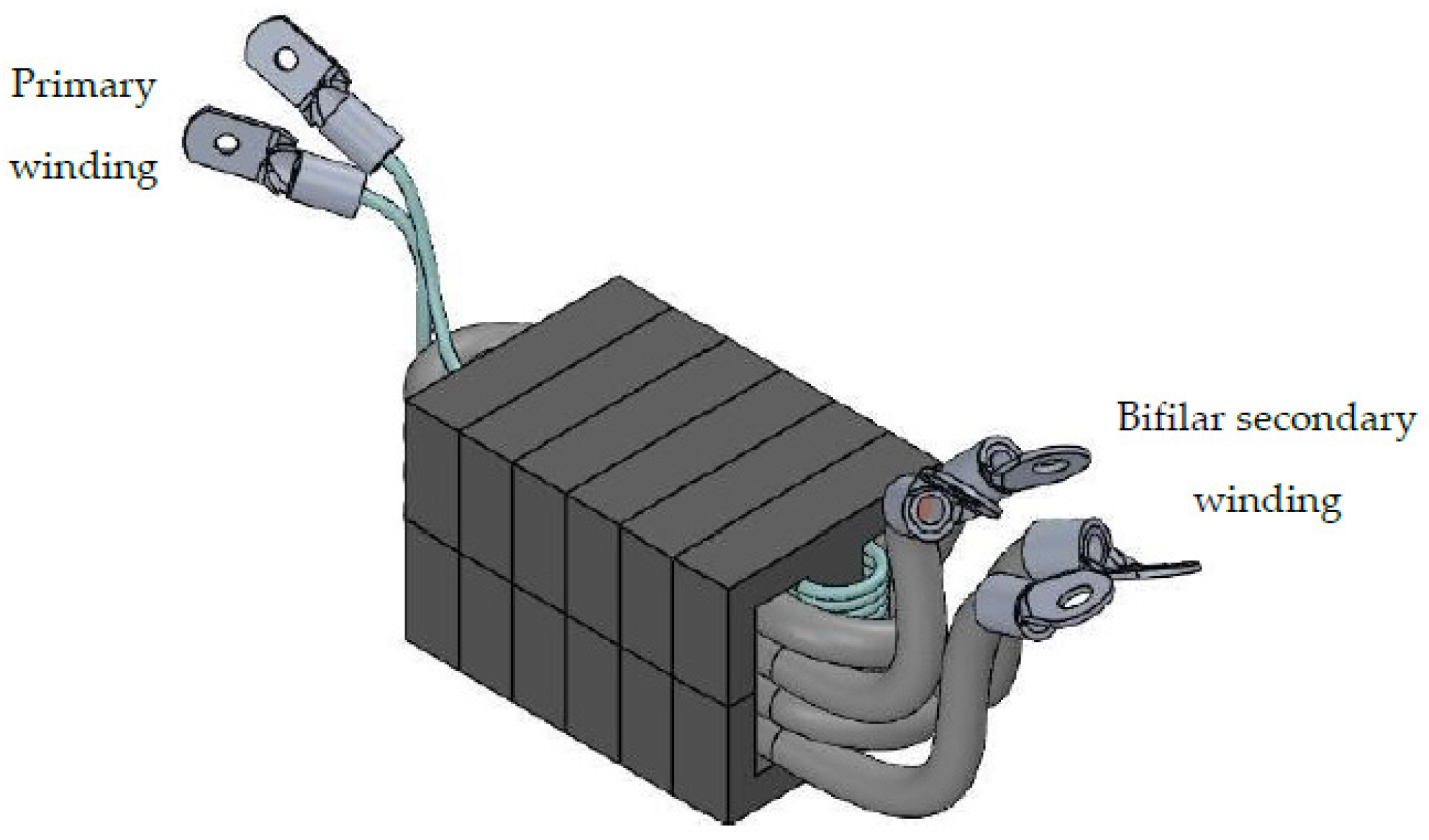
One typical 2-winding PET is shown in Figure 2. Its design optimization involves optimal use of core and copper; it is possible if both the core and copper losses are minimized. The copper loss Pcu depends on the current density of conductors, the impact of proximity effects on the resistance values of primary and secondary conductors, winding configuration and the construction of conductors [14,23]. On the other hand, the core loss Pcore depends on the properties of the core material, peak operating flux density Bm, the excitation frequency fs, the waveform pattern and the core temperature [18,19,24,25]. Thirdly, the design also involves devising a thermal circuit so that the temperature rise in core, copper and insulation are not only within the respective safe operating limit, but there should also be increased uniformity of maximum temperature rise in different parts of windings as well as in the core. Ensuring near-uniform temperature rise is complex because the distribution of power loss in the core is not uniform and so is the case for windings. Moreover, the thermal behavior of each circuit is also different. Ideally, for the design of the thermal circuit for heat removal, the average flux density per cycle is considered to be zero where the core loss is decided by the values of Bm and fs; it is true when the DC bias in core is absent [17]. The presence of DC bias could adversely affect the performance of the PET in several ways. Primarily, the core loss increases significantly under DC bias; it could work as a hindrance to draw any comparative statement on performance among different PETs. Secondly, depending upon the DC bias capacity of the magnetic circuit, there could be core saturation that affects the performance of the power controller. The DC bias capacity of the magnetic circuit is poor for zero-gap magnetic circuit using high permeability materials (e.g., toroidal core using nanocrystalline materials). The DC bias could be static [26] or dynamic [27,28].
Except in a few applications [8] where certain leakage inductance is desired, the design of PET necessitates that the two windings are overlaid on a small segment of the core volume [29]. Therefore, the bulk of its total power loss is concentrated around a small core volume (e.g., the central limb of Figure 2). Removal of such concentrated heat loss is a complex task. It would decide the operating limits of the core and the windings [21]. Large, concentrated power loss along with the constrained heat removal features of core and windings would result nonuniform temperature rise [3]. The respective value of maximum temperature rise would decide the capacity of core and windings. It forces the core to operate at reduced flux density because the maximum permissible operating temperature of core is less than that of copper or its insulation. It would affect the power density of the PET. To get the desired flux level, several cores are integrated. Until recently, for medium- to high-frequency PETs, ferrites have been prominently used to build the magnetic circuit. As shown in Table 1, for ferrites, the heat removal by thermal conduction is not attractive where the prospect of creation of hot spot is comparatively large [20]. The safe operating temperature range of ferrites is also not large and several of its parameters are sensitive to temperature [13]. Therefore, cores are usually integrated to achieve multiple goals, e.g., to meet the desired flux level, to have improved thermal conduction features to distribute the core loss over larger core surface area, to reduce the number of turns and layers in the windings, etc.
As detailed in [3], the temperature rise in various segments of core and copper is different; the safe operating temperature limit of each component of a PET could as well be different. For any power electronic component, for example, the differential value between its limiting temperature and maximum (hot spot) operating temperature would decide its utility as well as the service life [30]. The prospect of creation of hot spot temperature in copper is high on winding close to the core. The temperature of core is also maximum there [3]. The value of thermal conductivity K of core could play an important role in controlling the temperature distribution because, as shown in Figure 2, a major part of core assembly remains exposed to the surrounding environment. The bulk of power loss in a PET is concentrated around a small part of the core where primary and secondary windings are overlaid. Traditionally, to share the magnetic burden (flux density, core loss) equally, several cores of a similar type have been used to integrate the flux in the magnetic circuit and reduce the core loss density. Laterally, it would reduce the thermal resistance of the magnetic circuit. Often, for parametric matching dynamically, the. same batch code of cores has been strongly recommended. Now, wide-range soft magnetic materials possessing different parametric values are available. To improve the utility of a PET, can different core materials [12,13,25,31,32] be integrated in the magnetic circuit? What could be their characteristic features for integration in series or parallel configuration in a magnetic circuit to reduce either the power loss and/or to improve the thermal behavior of the PET?
The inspiration for this experiment-driven research has been the work reported in [3]. Using finite element analysis (FEA) and validated by requisite practical demonstration, it could correctly estimate the temperature distribution in different segments of core and copper. With the aim to improve the performance of PET, this article proposes, with detailed practical demonstration, to integrate different soft magnetic materials into the magnetic circuit. Here, an improved thermal conductivity and/or reduced loss density of the new core placed in a zone of high power loss is aimed to aid the cooling of regions of maximum heat generation. The structure of the article is organized as follows: Section 2 details the features of PETs for two different characteristics applications—one used for voltage ratio and the other for current multiplication. It also discusses their design issues. Section 3 details the different perspectives of two types of mixed-core configuration suitable for two different applications. To take care of important issues such as the magnetic compatibility, etc., it also introduces application specific suitability factor for integrating different soft magnetic materials into the core. Finally, Section 4 details the practical validation of mixed-core, air-cooled transformers for two different application domains.
2. Power Electronics Transformer for Divergent Load Characteristics
Any new idea needs to be validated in different application domains. A PET is used to make the load compatible to the source; it could be achieved in several ways. A PET could be part of power transfer in PWM controlled full-bridge DC−DC converters (FBDC) [21,33], resonant converters [6,34] or for feeding a resonant tank circuit [4]. The nature of waveforms of current and voltage could change in applications. The PET could be used for voltage ratio where, at zero output power, the current in windings could be zero, or it could be used for current ratio where its primary voltage is decided by the load. In the first case, the magnetic circuit could remain loaded and the value of copper loss Pcu could be zero at no load. In the second case, irrespective of the magnitude of the delivered power, the windings always draw the set current. The value of the core loss Pcore is negligible at zero power.
Achieving optimum power density of a PET is a major design goal [35]. It depends on the total power loss and the design of thermal circuit. The PET is said to be thermally loaded to its capacity when the rated power, say, , is delivered to the load. Traditionally, the area product AwAc in Equation (1) is used to define the extent of optimization of a PET. At a particular frequency fs, it suggests a large value of Bm in core as well as the current density J in copper windings, as given below,
The expression of Bm for a square wave input voltage Vin is,
Aw is the window area, Ac is the core area and np is the number of primary turns.
For effective use of a PET, its core loss Pcore [18] and copper loss Pcu [23] need to be calculated accurately. For sinusoidal primary voltage, the Steinmetz equation [16] is used to calculate the value of Pcore; its parameters are mostly mentioned in core datasheet. However, in high-frequency applications, the primary voltage is rarely sinusoidal. Using the same Steinmetz parameters, the improved generalized Steinmetz equation (iGSE) is used to calculate Pcore for any input voltage waveform [17,19]. Using the iGSE, the expression of Pcore with square wave excitation is,
where .
KS, α and β are Steinmetz parameters, dpwm is duty cycle of square wave input and Wc is the core weight. For pure square wave input (dpwm: 1.0), Equation (3) may be modified to,
The expressions of in primary (Ppri) and secondary (Psec) windings are,
F1 and F2 are the ac resistance factors, ip and is are the primary and the secondary current, respectively, and rdc1 and rdc2 are their respective dc resistance values. Both F1 and F2 depend on several factors such as skin and proximity effects where proper choice of copper conductors (litz wire or thin foil) and layout of windings are important [23].
The popular geometry of the magnetic circuit could be based on any of EE, UU or CC as shown in Figure 3a, or zero-gap toroidal shaped cores of Figure 3b. The dynamic profile of the input voltage Vin decides the value of Bm in core; it depends on the power controller and the characteristics of the connected load. Depending upon the value of Bm, the magnetic circuit could face nonlinearity as well as the magnetic saturation. Here, two application types are considered where the dynamics of Vin or Bm are completely different.
2.1. PET for Full-Bridge DC−DC Converter (FBDC)
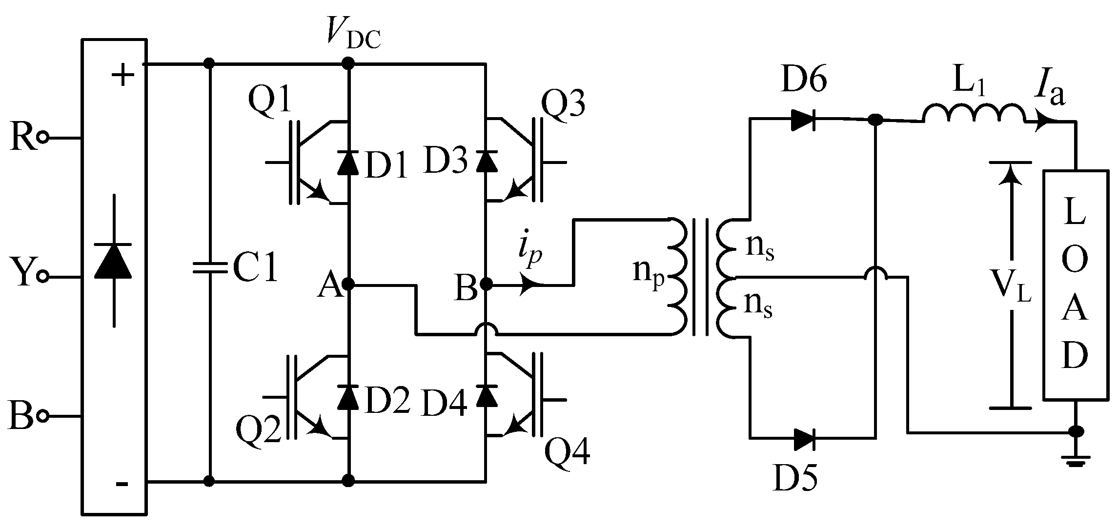
One typical circuit of FBDC is shown in Figure 4. Here, the magnitude of output current depends on the power drawn by the applied load at voltage VL and its effective resistance, e.g., battery charging [11], arc welding [33], etc. Even at zero load current the cores could be fully loaded. For a nonlinear load (e.g., welding arc), the dynamic control of DC current Ia would decide the value of Vin or Bm through dynamic change in dpwm, such as,
VDC is the supply voltage, is the ratio of primary (np) to secondary (ns) turns, k1 is constant and the control is used to ensure zero current error. The transient disturbance in the arc welding process is large [28].
The permissible value of J in windings would be decided by several factors such as values of F1, F2 and dpwm. For the arrangement of secondary side rectifier of Figure 4, the primary current ip and the current is in each bifilar secondary could be expressed as,
If care is not taken, there could be error in Pcore because the core in FBDC often faces both the static or dynamic DC bias. The static DC bias could be compensated by a simple approach [26]. The dynamic DC bias [27,28] in core would depend on how the control u (or dpwm) reacts to ripple in steady state error as well as the load transients. The DC bias is more prominent when the loop gains are large where the ripple in Ia becomes transparent in control input u [28]. Under DC bias conditions, the values of Steinmetz parameters drifts.
2.2. PET for Series Resonant Induction Heating Equipment
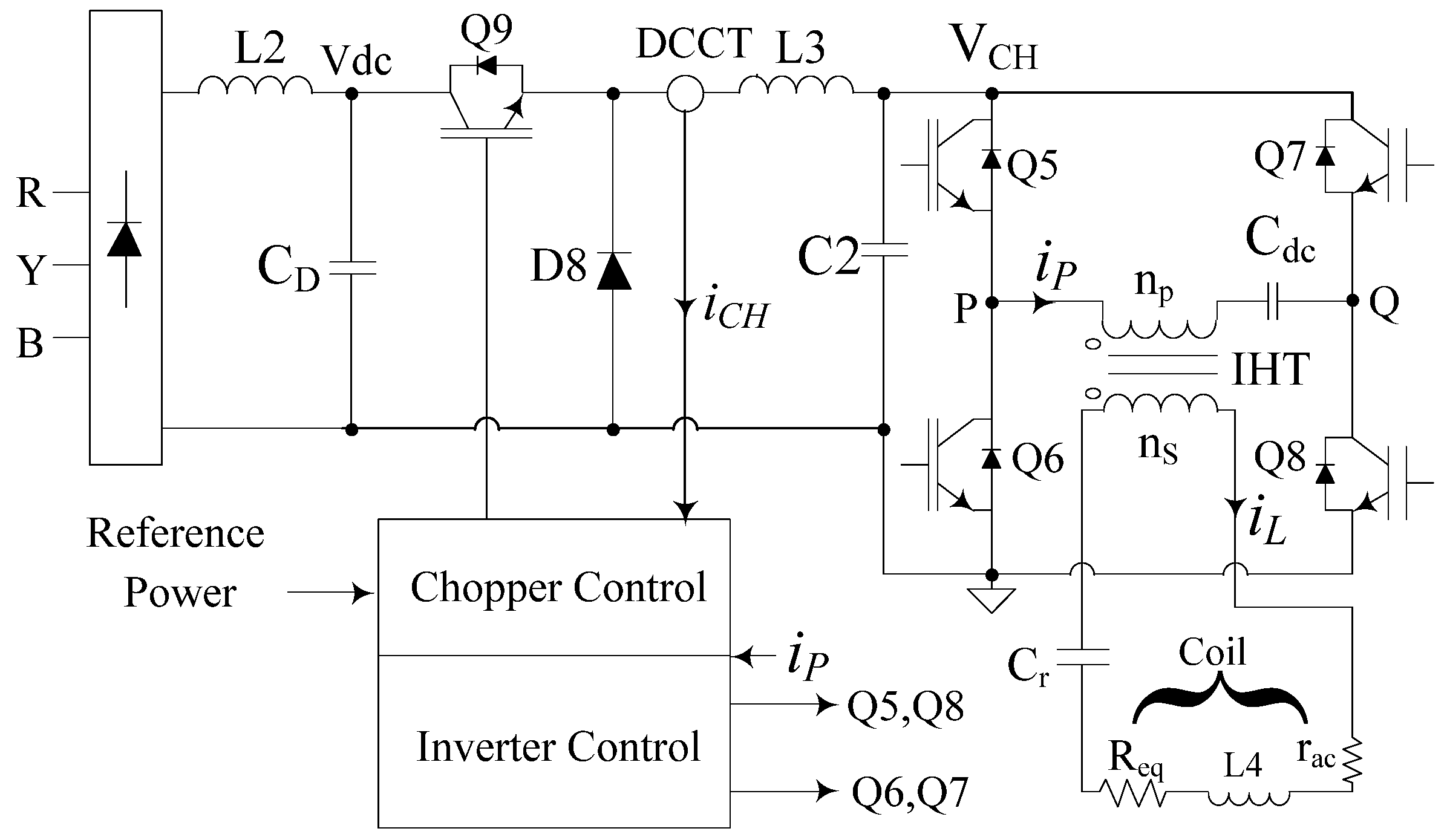
The characteristics of the connected load to PET as well as its associated dynamics is quite different in induction heating. Here, the coil head L4 is kept energized with rated current iL at the frequency decided by the tank circuit parameters L4 and Cr. The coil facilitates the power transfer when a metallic object is taken close to the coil. For a noncontact mode of power transfer, normally, the coil current iL is kept large. To reduce the stress on primary side components, as shown in Figure 5, the induction heating transformer (IHT) is used to step up the inverter current. The value of Pcu is always at its rated value. The loading of its magnetic circuit and hence the core loss Pcore depends on the power POUT drawn through L4; it depends on multiple parameters, such as,
L4 is the inductance value of coil, iL is the coil current, fs is frequency of iL and the parameter Kc depends on coupling between the coil and the load. Req represents the effective load resistance reflected in the tank circuit.
The input voltage to IHT is a square wave , but the current in both the windings are pure sinusoidal. The DC blocking capacitor Cdc is connected to eliminate any static DC bias present in the core. Zero voltage switching (ZVS) condition of switches Q5–Q8 is inherently achieved because the phase-locked loop (PLL) ensures fs at slightly higher than the resonant frequency . Plus, the buck converter controls the input voltage Vin to achieve near-zero current switching of Q5–Q8. Under ZVZCS condition, the inverter input voltage VCH or the primary voltage of IHT could be approximated as,
where rac is the ac resistance of L4 and n is the turns ratio of IHT. At no load, the value of Bm is negligible because the value of is small. The change in load of IHT, i.e., the change in Req is never abrupt. Its value increases when a job is brought close to the coil (i.e., when more power is drawn through L4), and decreases gradually either near the Curie point or when the job is taken away from the coil head mechanically. They ensure that the dynamic change in Bm is also not abrupt. Moreover, the response time of the buck chopper decides the dynamics of Vin. Therefore, the prospect of dynamic DC bias in IHT would be small. Furthermore, the slow dynamic DC bias in the core, if any, could be effectively tackled in the PLL loop [36].
The design of IHT involves deciding on the values of np and ns; selecting a core material of suitable geometry to afford optimal values of Bm and J. In ZVZCS conditions, the value of n would be maximum at nmax because the load behaves as resistive,
At , the current is minimum in the primary winding and the length of conductor used in the secondary is also minimized, and together they help minimize Pcu. Large values of Bsat and small values of Pc of nanocrystalline cores would allow optimal choice of np as well.
Secondly, for efficient transfer of power , tracking of fr should be accurate. The value of Req would be more at higher values of fr [37]. When L4 is loaded, its inductance value drifts down to, say, Leq; then, the corresponding value of fr is,
Llk is leakage inductance of IHT; its large value would be a hindrance to effective power transfer [37]. The value of Llk is small for high-permeability ungapped toroidal cores.
Thirdly, the primary current ipri consists of triangular wave magnetizing current with peak at Im plus the reflected sinusoidal coil current iL. For minimum phase error between Vpri and ipri of IHT, the value of Im should be small; it is expressed as,
where lm is the mean core length. A large value of µr is needed for small value of Im and np.
For IHT, the high-permeability nanocrystalline material-based ungapped toroidal cores (shown in Figure 3b) would be preferred [15,38,39,40], particularly because the DC bias in the core is negligible. Laterally, these cores would ensure small values of Im and Llk and also the minimum of number of turns where the value of Bm would be large.
3. Mixed-Core Transformer Configuration
It was clear in Section 2.1 and Section 2.2 that the type of application or load characteristics could influence the design of PET. The nature of loading of magnetic circuit, in particular, could vary in applications, e.g., the value of Pcore could be fixed and that of Pcu would be decided by the load. Along with reducing the core and the copper losses, the optimization process involves design of a thermal circuit to ensure near-uniform temperature rise in core and also in copper so that the PET is enabled to deliver more power. Due to multiple loss centers, the thermal circuit of the core and windings are coupled. For the magnetic circuit, the distribution of heat and its removal by thermal convection could be improved if the value of K as well as that of the surface area of core are increased. To have requisite flux AcBm, several cores are integrated. Often, for magnetic compatibility, cores of the same material with the same batch code are preferred. It is important to find whether such arrangement is best suitable for efficient heat removal, both from the core assembly as well as from the windings. On the other hand, can some other combinations, such as the hybrid core configuration, manage the heat loss or the thermal issues better?
3.1. Thermal Behavior of Power Electronic Transformer
As shown in Equations (3) and (5), the values of Pcore and Pcu, respectively, increase exponentially with Bm and with . The design optimization of a PET is complex because the layout of the windings and thermal behavior of the PET often contradict. As shown in Figure 3a,b, two windings are overlaid for better magnetic coupling and also for reduced eddy current loss in core [29]. Such arrangement needs good heat removal features because the bulk of total power loss is concentrated around a small core segment where the secondary winding is laid above the primary. Removing the heat loss from the multilayered primary winding is difficult because there exists insulation on either side of each layer and also between the windings. The prospect of creation of hot spot is more in the primary [3]. Furthermore, due to the increased impact of the proximity effect, the value of Pcu would be more in multilayered winding. Though the thermal circuit of PET is coupled in a complex manner, the limiting values of Bm and J would be decided by the effectiveness of the thermal circuit [3,39,40]. With given loss, the safe operating temperature for the core would depend on the soft magnetic materials and that for copper would be on the insulation of litz wire strands as well as that placed between the layers.
Due to the complex nature of the thermal circuit, there exist multiple heat conduction channels with different heat transfer coefficients, and they are mostly coupled [3]. The directions of heat flow would be decided by the location of the hot spot temperature Ths of the PET; it could be decided by the temperature differential , such as,
is the effective thermal resistance of the PET and Tamb is the ambient temperature. RPET mostly consists of thermal conduction (Rth) and thermal convection (Rconv). Though it plays certain role, the heat transfer by radiation is ignored here. For compact design of PET, apart from reducing the total loss Ptot, the value of should be minimum. Large surface area of the core and the secondary winding are available for heat transfer. The major part of Ptot is removed by thermal convection [21,41,42] where the speed of the moving medium would play a significant role. The expressions of conductive and convective thermal resistances are,
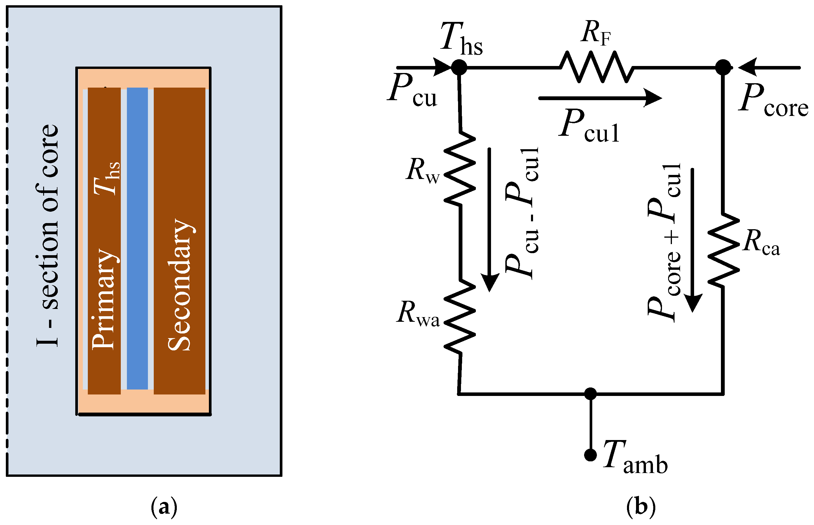
Acond and Aconv, respectively, are areas available for conduction and convection and hcond and hconv are corresponding heat transfer coefficients. The value of hconv depends on thermal conductivity of the attached medium and also on its speed where fan cooling improves its value significantly. Backed by practical validation, the finite element method (FEM) was extensively used to establish reasons behind the formation of hot spots in core and copper in high-power transformers [3]. It was realized that the temperature rise in copper was alarming on multilayer winding with constrained heat transfer features, e.g., the primary winding of Figure 3a. In multilayer winding, a significant part of Pcu is concentrated in the internal layer of primary winding closest to the core where the proximity effect is more prominent. The hot spot temperature Ths is located here; its value needs to be reduced. It could be made possible if a part of Ppri close to I-section, in particular, is channelized to the ambience through the core. Considering the heat conduction is symmetrical around the I-section of Figure 3a, the overall heat conduction circuit of half of the PET (shown in Figure 6a), is represented in Figure 6b. The part Pcu1 of total copper loss Pcu that could be channelized through the core is expressed as [41],
Rw and Rwa, respectively, are the conductive and the convective resistance of the winding, and RF and Rca, respectively, are the effective thermal resistance of the coil former and the core. It is clear that more heat loss (i.e., Pcu1) would be channelized through the core if either of Rca or Pcore or together could be reduced through design or selection of suitable soft magnetic material; reduction of RF would also play certain assisting role.
To achieve the abovementioned objective, it is proposed to use a mixed-core configuration for the magnetic circuit. It is known that a small fraction of core volume handles most of Ptot while the major part of its surface area is exposed to the ambience. Therefore, if that particular small section of core volume is replaced by a suitable soft magnetic material, then better heat removal feature by convection and radiation could be realized. The new core material is desired to possess following features:
- Superior thermal conductivity.
- Reduced core loss density.
- Higher maximum operating temperature than the parent core.
- The new material must be magnetically compatible.
Basic features of different soft magnetic materials are listed in Table 1.
3.2. Magnetic Compatibility of Different Types of Magnetic Circuits
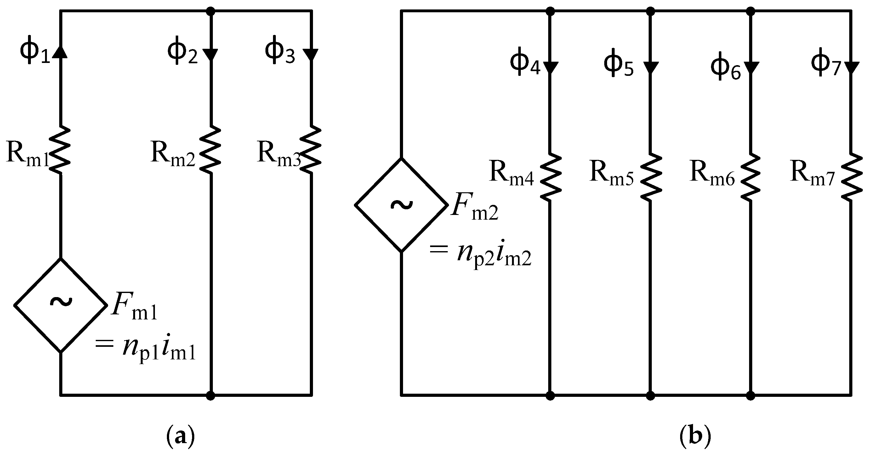
For a given magneto motive force (MMF) Fm, the magnitude of magnetic flux φ linking the windings is decided by the reluctance value Rm of its magnetic circuit. The reluctance circuits of the core assemblies of commonly used high-power PETs of Figure 3a,b could, respectively, be represented in Figure 7a,b. Traditionally, the value of loss density Pc is considered at the same value everywhere. It means, for one type of cores, the value of Bm should be same everywhere. However, in the proposed idea of using the mixed core configuration, the value of loss density could be different. The expression of flux φ linking the windings is,
It is desired to have , and it could be achieved when is met.
For the magnetic circuit of Figure 7b, considering the same value of reluctance in each circuit, the total flux in the core assembly could be expressed as,
where im2 is the magnetizing current and np2 is the number of turns at primary. Neglecting the dimensional tolerance of the cores, the dynamic value of Rm of each parallel path plays an important role in flux distribution. When composite core segments are used, the dynamic behavior of µr becomes critical for designing the magnetic circuit of Figure 7b. The value of µr could change differently with respect to operating value of Bm, fs, temperature, etc.
Characteristics of Different Soft Magnetic Materials
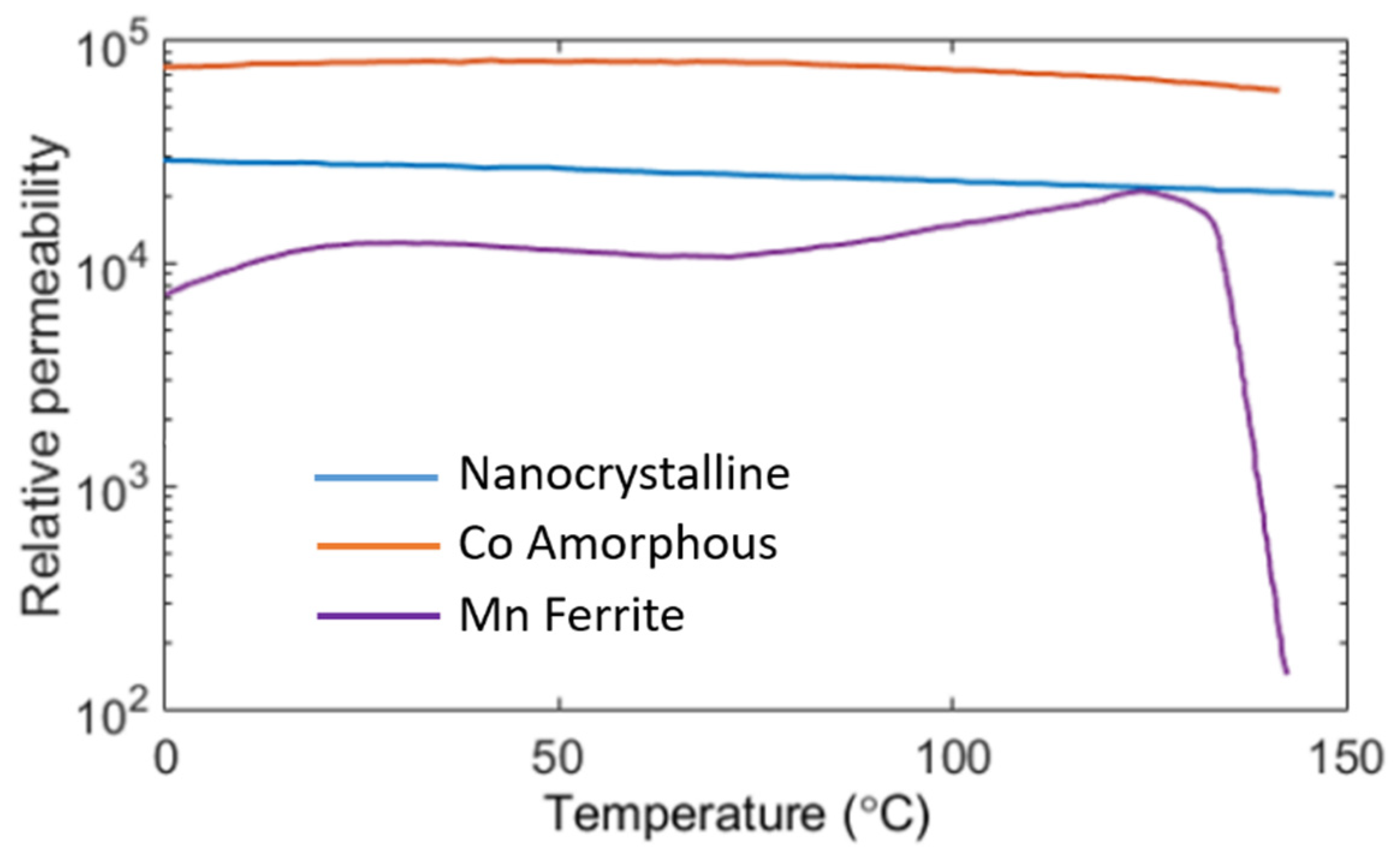
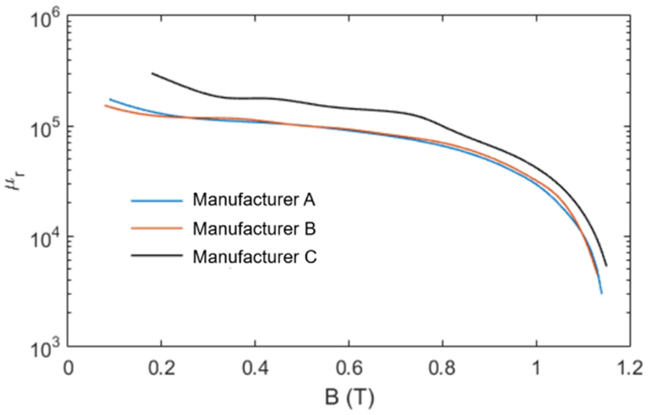
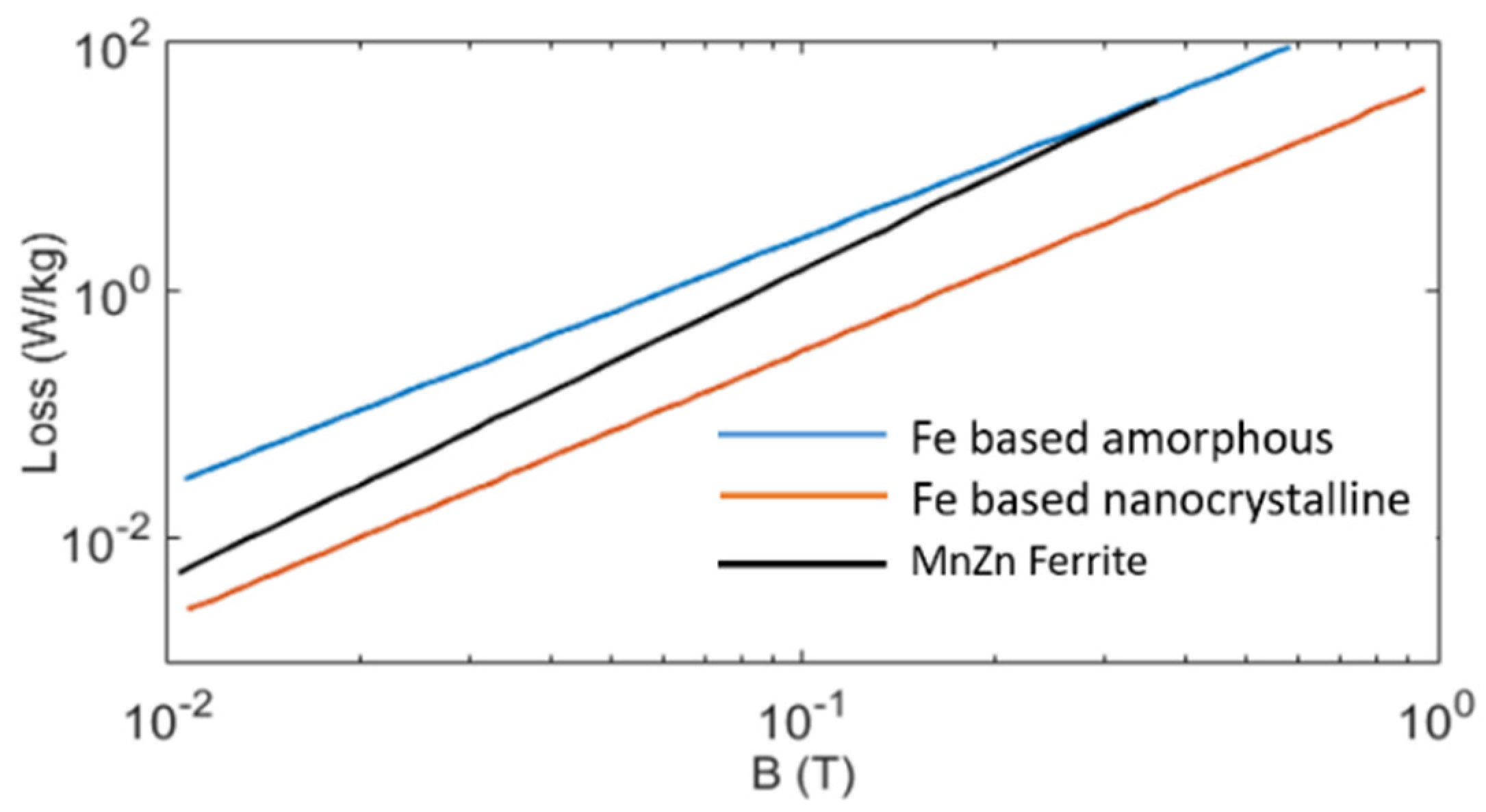
It is clear that for the magnetic compatibility, the role of relative permeability µr is extremely important. For better thermal performance, the heat distribution (Equation (15)) should be proper, i.e., more heat needs to be transferred to the core surface area exposed to the environment. Here, both the core loss density Pc and the thermal conductivity K would play significant roles. The basic parameters of popular soft magnetic materials are listed in Table 1 [20]. For ferrite cores, the parametric variation with respect to temperature [13] is large. Compared to others, its Curie temperature is much lower. The reduction in Bsat value vs. temperature is also sharp. For integration of different core types into a magnetic circuit of PET, the value of µr at different flux density and core temperature is important. The influence of temperature on µr of different soft magnetic materials is shown in Figure 8 [43] where nanocrystalline cores appear to be parametrically robust. It is also known that, for ferrite cores, the value of µr changes significantly with flux density [4]. However, for nanocrystalline cores, as shown in Figure 9, the value of µr is mostly constant, and only at large values of Bm is there gradual monotonic drooping in its value. Moreover, compared to other soft magnetic materials, the core loss of nanocrystalline cores at a particular frequency is comparatively less at any flux density (shown in Figure 10). Therefore, due to the parametric robustness, small core loss density, superior thermal conductivity, higher saturation flux density and high Curie temperature, the nanocrystalline cores of proper ribbon thickness are superior candidates for mixed-core configuration. It would not disturb the behavior of the magnetic circuit. If geometry permits, Fe-based nanocrystalline cores could ideally be suitable as flux integrators for medium- to high-frequency PETs. The drooping characteristics of µr, as shown in Figure 9, make these cores suitable for integration into a magnetic circuit where the MMF feeds several parallel magnetic circuits (shown in Figure 3b).
3.3. Figure of Merit of Mixed-Core Magnetic Circuit for Series Reluctance Model
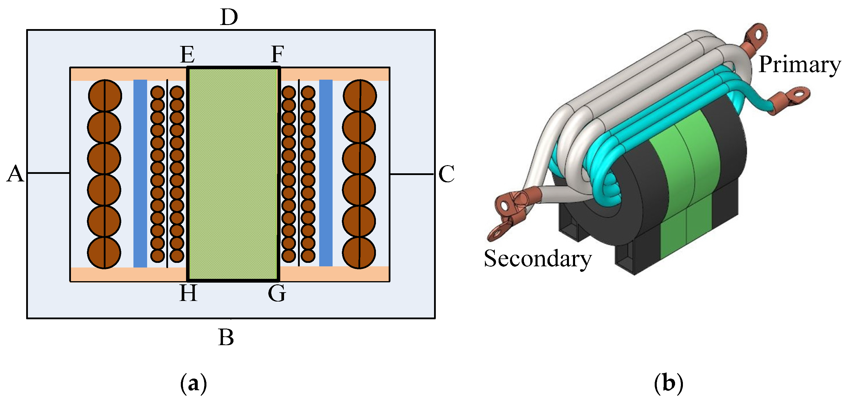
It is known that for the PET of Figure 3a, the bulk of total power loss Ptot is concentrated around the central I-section EFGH. The hot spot temperature in the core and the primary winding, in particular, would reside in and around the I-section [3]. In order to properly utilize the large surface area of core exposed to the ambient medium for thermal convection and radiation, there needs to be an improvement in spreading the heat loss in the core by thermal conduction. A higher value of thermal conductivity K of core in the I-section EFGH would help remove the concentrated heat loss to the surface area of the magnetic circuit. As detailed in Equation (15), more power loss could be channelized if,
- The value of Pc of the I-section is small.
- The value of K of soft magnetic material used in the I-section is more.
- The value of thermal resistance in coil former is reduced.
The first two features could simply be achieved if the central I-section is replaced by a geometrically compatible core material (shown in Figure 11a) with superior features so that the value of (see Equation (13)) in the I-section of core is reduced. The compatibility of the new material would be based on its dynamic magnetic parameters, core loss density Pc and the value of K. From the magnetic characteristics point of view, the role of I-section is not complicated. The Figure of Merit of the new core material for the I-section could be gauged by a suitability parameter Score(SR); it is introduced in simple form as,
When compared with parent material, a smaller value of Pc and the same or larger value of K would result in superior distribution of heat in core. The permeability µrn of new I-section should be around the same value as µrp, i.e., of parent material. The value of K and other relevant parameters for different core materials are listed in Table 1.
3.4. Figure of Merit of Mixed-Core for Parallelly Connected Magnetic Circuit
Multiple toroidal cores are stacked (shown in Figure 3b) to support the desired flux level in the core of IHT. It is difficult to remove the heat loss from each core uniformly. The surface area of inner cores exposed to the ambient medium is relatively much less. It could lead to differential temperature rise across the core segments. In practice, the inner cores are found to be hotter. Like the PET of Figure 11a, here as well, as shown in the arrangement of Figure 11b, the problem could be reduced if the inner cores are replaced by a superior material. For a magnetic circuit where cores are used in parallel, it is difficult to establish the desired flux density everywhere. The dynamic value of relative permeability of each core being integrated would play an important role. To find the compatibility of the new core material for parallel reluctance model, and also to take care of sharing of flux, the suitability factor Score of Equation (19) is modified to,
where µr(Bm) is the value of µr of core at the operating value of Bm. It takes care of the distribution of flux when the condition is met. As shown in Figure 9, nanocrystalline cores support such characteristics. Furthermore, as shown in Figure 8, the value of µr for this core is also stable against temperature.
4. Experimental Validation of Mixed-Core Transformers
To validate the proposed idea of improving the thermal performance of a mixed-core PET, two divergent application domains were considered. In the first, to ignore any role of DC bias, the magnetic circuit was completed using two UU cores. In the second case, because the dynamics of Bm were sluggish, the ungapped toroidal shaped cores were assembled. In the first case, the prospect of transient DC bias was more. The magnetic circuit needed to be built with large DC bias capacity where, for large power applications, EE, UU or CC cores were suitable. On the other hand, for IHT, the prospect of transient DC bias was small. Therefore, ungapped toroidal cores with large permeability were preferred in the magnetic circuit.
4.1. Validation of Mixed-Core PET Where the Magnetic Circuit Uses UU cores
Ferrite cores in EE or UU shape are prominently used in high-power PET of Figure 3a where the central limb hosts both the windings. Due to their superior characteristics, as described in Equation (19), nanocrystalline cores would ideally be preferred for the I-section of Figure 11b. However, these ribbon-type cores are not dimensionally compatible as yet with the commonly available ferrite cores. It is difficult to match important dimensions one-to-one, e.g., the core area Ac, the window area Aw, the mean magnetic length lm, etc.
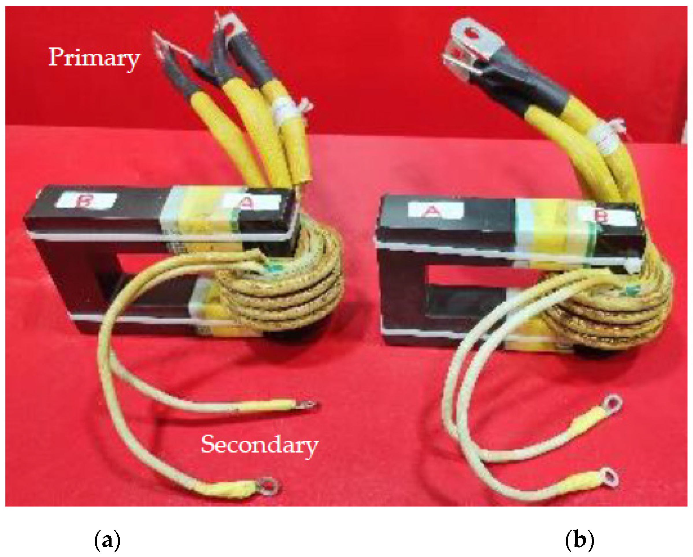
It was difficult to procure I-shaped nanocrystalline cores physically or geometrically compatible to commonly used UU or EE ferrite cores. Therefore, to study the role of K and Pc on the thermal performance of PET, as shown in Figure 12, two mixed-core transformers (MCT) were built using different ferrite cores with different values of Pc and K. For core assembly, each MCT combined two different core types A and B procured from separate manufacturers. Relevant parameters of these cores are listed in Table 2.
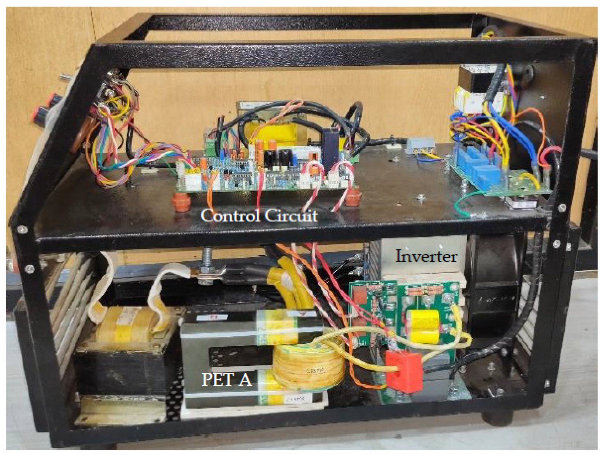
For testing of PETs A and B of Figure 12, one 20 kHz full-bridge DC−DC converter (shown in Figure 4) operating at 20 kHz was developed. The power controller is shown in Figure 13. For switching of inverter, IGBTs (Type: 2MBI075VAA-120-50) were used. The value of VDC was 560 V. The value of inductor L1 was 100 µH. The winding layout of PETs A and B was similar, each had two secondary bifilar windings. To practically compare the magnetic compatibility at high flux density, the turns-ratio np:ns:ns of PETs was deliberately chosen at 24:2:2. The value of Bm at maximum value of dpwm at 80% was 0.325T. Moreover, at the rated output power PL at 4.5 kW (PWM duty cycle dpwm ≈ 57%), the magnetic circuit would be loaded to the rated value of Bm at around 0.2 T. Each PET used one pair of UU cores, the value of Ac was 8.4 cm2. At rated load current (Ia: 200 A) with dpwm at 57%, the current density J (A/mm2) at primary (strand dia.: 0.1 mm, 450 strands) and secondary litz wire (strand dia.: 0.1 mm, 3780 strands) conductors were 3.56 and 4.72, respectively. Due to higher value of J, the power loss in secondary conductors was more.
Two sets of waveforms with an exactly similar nature of the magnetizing current im1 (both secondary: open) in Figure 14a,b demonstrated that the core A and B were magnetically compatible even in the nonlinear zone of the B–H curve. At dpwm of 80%, the value of Bm was deliberately kept large at 0.325 T so that the magnetic compatibility in the nonlinear zone was verified. The magnetic circuit had rated value of Bm (≈0.2 T) at designed power output.
To evaluate the thermal performance comparatively, the two transformers were (resistive) load tested until the temperature in core and copper stabilized. The ambient temperature was 28 °C. The delivered power to load was 4.5 kW where the load voltage VL was maintained at 22.5 V. At full load, the calculated value of Bm was 0.207 T. Various waveforms of the FBDC using PET A and PET B are shown in Figure 15a and Figure 15b, respectively. Using the Fluke make 59 Mini IR thermometer, the temperature was recorded in each winding and also in the core segment close to the windings. The measured value of the hot spot temperature in the core and the windings of two PETs are listed in Table 3. It was clear that, compared to PET A, the temperature distribution of PET B was superior. The experimental results made it clear that the core type with lower value of Pc and/or possessing higher value of K would be more suitable for the core segment where the windings are laid. It could be stated that the situation would improve further if the I-section was replaced by a suitable nanocrystalline core material.
The results detailed above were found to be reproducible when thermal images of PET A and PET B were captured by a camera (model: FLIR AX 5). In the captured images, the hot spot temperature of the secondary winding (SP1), primary winding (SP2) and also in the core (SP3) for two different case studies are shown in Figure 16 (for PET A) and in Figure 17 (for PET B). It was clear that the core of reduced value of Pc and of larger value of K helped reduce the hot spot temperature of PET B. The results mostly tallied with the findings of the temperature profile obtained through the noncontact type Fluke make 59 Mini IR thermometer.
4.2. Validation of Mixed-Core IHT for Parallelly Connected Core Assembly
The loading pattern of the magnetic circuit of IHT is different. The value of Pcu is desired to be minimized because it is always at its rated value. It was analyzed in Section 2.2 that the ZVZCS topology along with using a low-loss magnetic circuit with a high effective value of µr and high saturation flux density Bsat would simultaneously minimize the copper content in IHT and also the value of Pcu. It requires the core to operate at a large value of Bm where cores with low loss density and high values of Bsat would be suitable. When both windings are placed in single layers, the impact of proximity effect on Pcu is minimized. Laterally, it would achieve better features for heat removal because windings are exposed to the ambient medium. For the magnetic circuit, the ungapped toroidal cores using nanocrystalline material would be a preferred choice because:
- The value of magnetizing current would be small.
- The value of leakage inductance would be negligible.
- IHT does not need large DC bias capacity; transient load disturbance is small.
- For large value of Bm (>0.25 T), ferrites are not suitable.
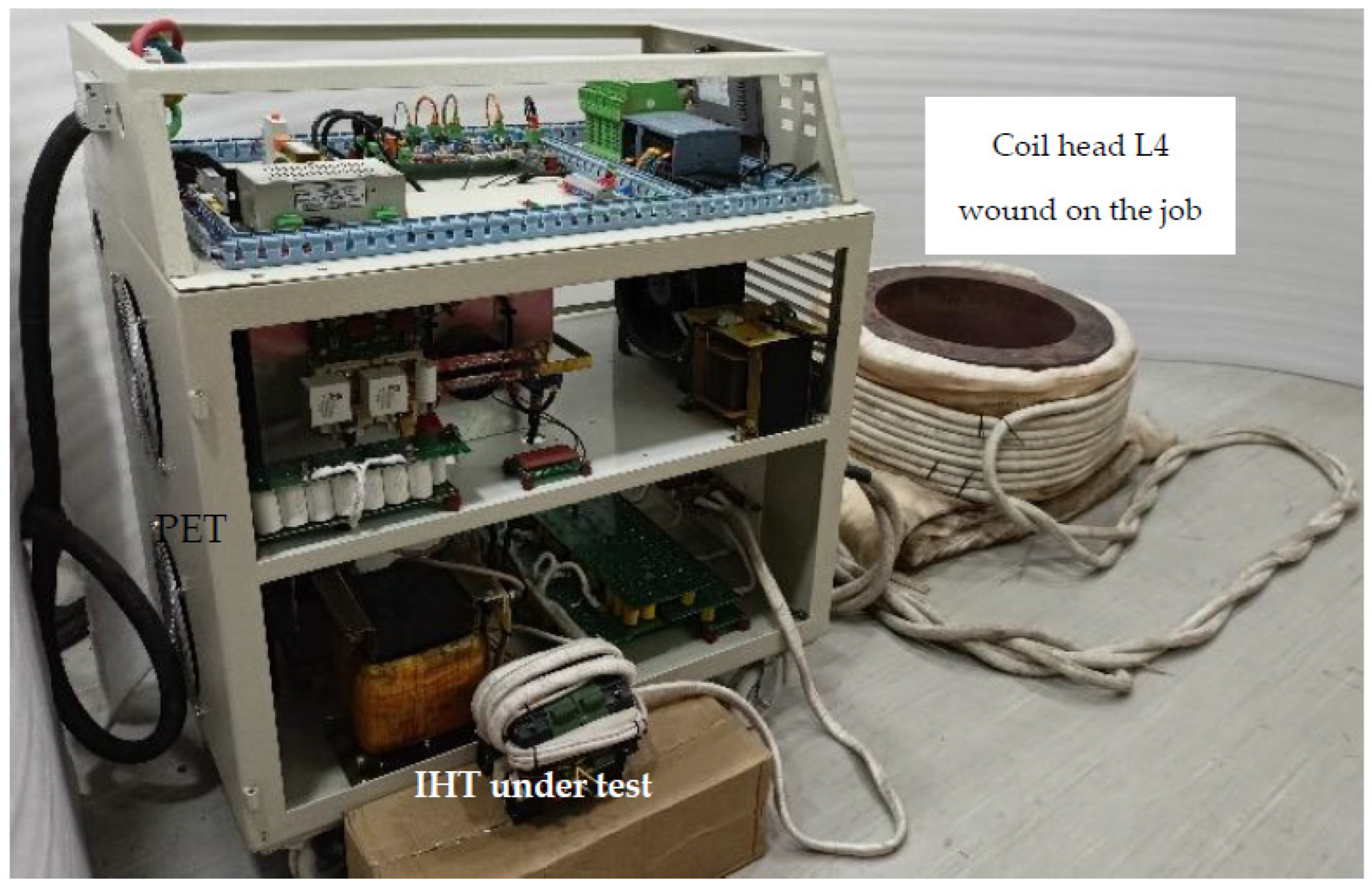
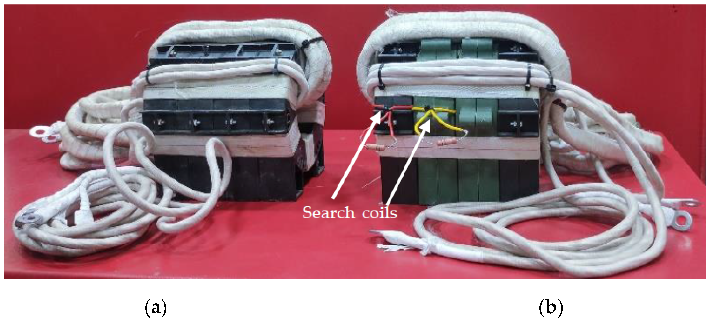
To practically study the usability of the proposed MCT, one induction heating controller was developed to deliver 40 kW output power. The complete experimental set up is shown in Figure 18. For comparative analysis, two transformers, i.e., the traditional single core-type IHT I and the mixed-core transformer IHT II, were designed using nanocrystalline cores. As shown in Figure 19a, in IHT I, four similar cores of, say, material type C, were stacked. Whereas in IHT II, as shown in Figure 19b, two poorly ventilated central cores were replaced by cores of different material, say, type D. The parametric details of both C and D type cores are listed in Table 4. Due to the reduced thickness of ribbons, when compared with core C, the value of Pc in core D was less. Naturally, the core D resulted superior value of Score(PR) (see Equation (20)). The operating parameters of the inverter and cores are listed in Table 5. To study the magnetic compatibility, one single-turn search coil was wound on C and D cores each (shown in Figure 19b). The turns-ratio of each IHT was 8:3. For the tank circuit, the value of L4 was 52 µH and that of Cr was 3.6 µF. The inverter frequency was 12.5 kHz. With set coil current at 250 A, the value of J in primary (strand dia.: 0.1 mm, 2880 strands) and secondary (strand dia.: 0.1 mm, 2 × 3780 strands) conductors were 4.15 A/mm2 and 4.21 A/mm2, respectively.
Initially, the magnetic compatibility of cores C and D in the IHT II was tested for three different operating conditions; they are:
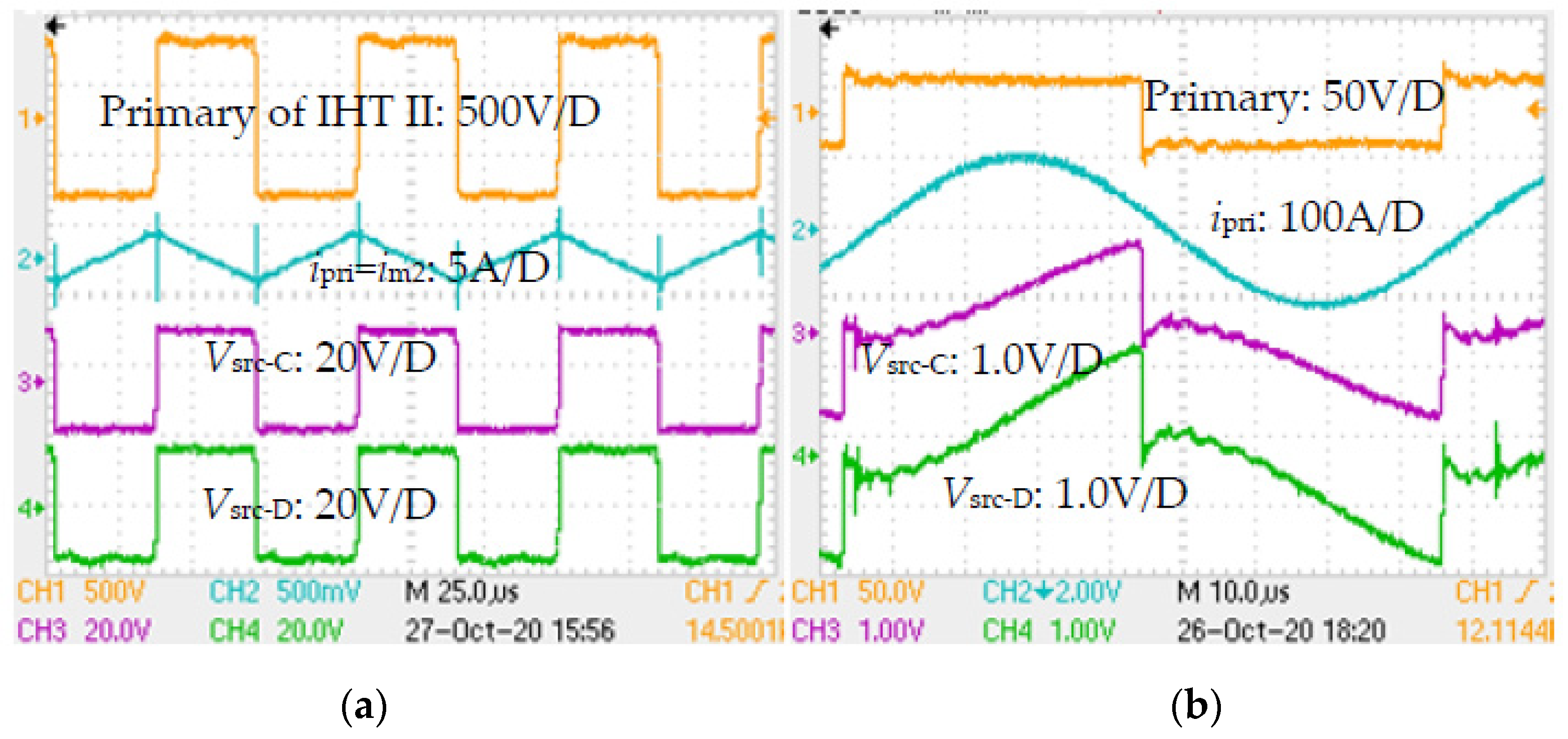
- The magnetic circuit operated at maximum value of Bm when the secondary was kept open and the primary was excited with full voltage. The control circuit was disabled. The current at primary was the magnetizing current. Waveforms in Figure 20a validated that the two core types were magnetically compatible. Exactly similar nature of induced voltages in the single-turn search coils Vsrc-C (core C) and Vsrc-D (core D) proved that the flux density was shared appropriately.
- The tank circuit was connected, but the power delivered through the coil head was zero. Moreover, there was a DC blocking capacitor Cdc of 100 µF added between primary of IHT II and the inverter output. The primary voltage was small. Here, as well, the two core types were found to be magnetically compatible (shown in Figure 20b) because even at very small flux density the readings in both the search coils were similar dynamically.
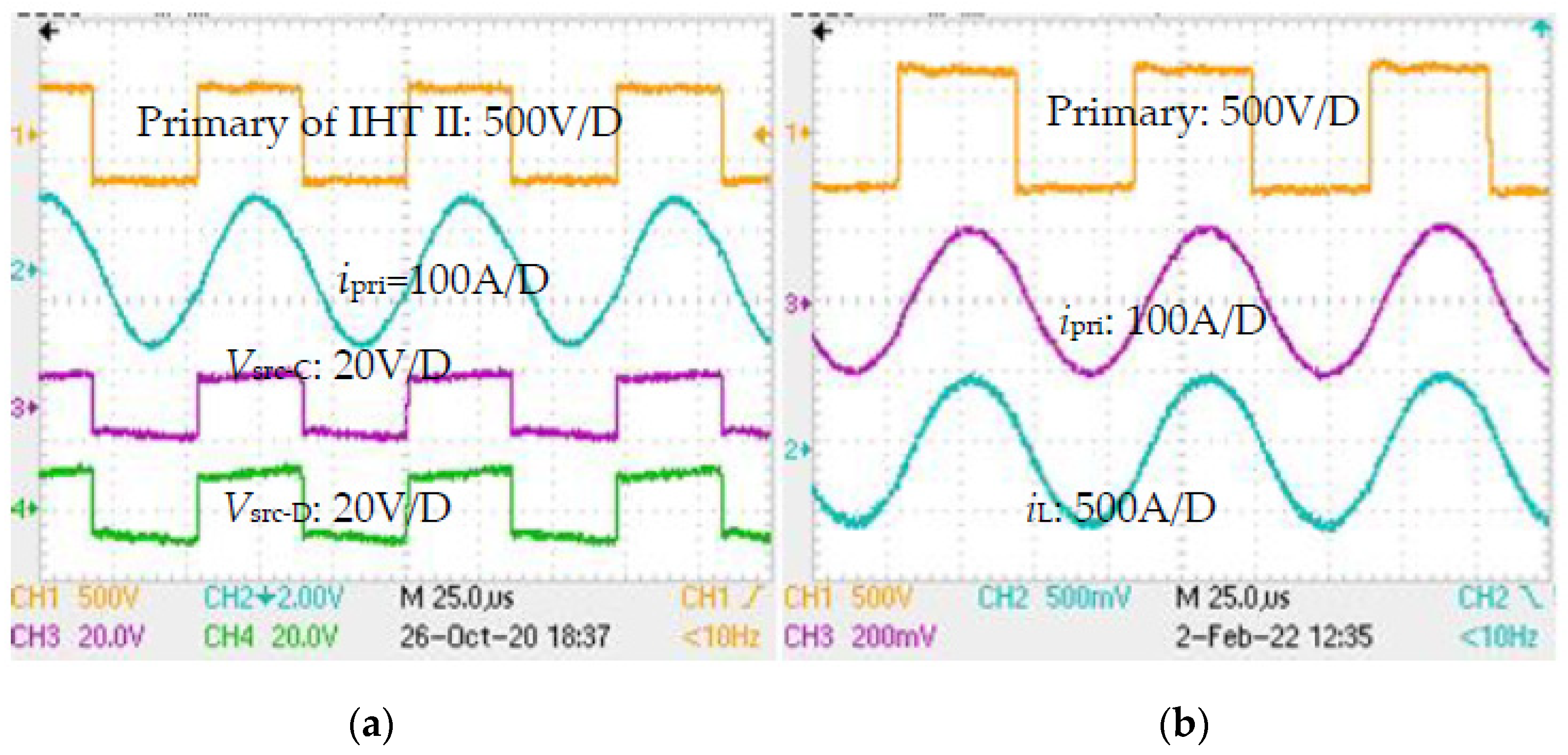
- Magnetic compatibility of cores of IHT II was also tested when the secondary was loaded. The coil head L4 was loaded at 20 kW. The necessary waveforms are shown in Figure 21a. Here, as well, the voltage waveforms of both search coils appeared similar—in magnitude as well as in waveshape. Similar search coil voltage readings at zero secondary current as well as under loaded condition proved that cores C and D were integrated into the magnetic circuit of IHT II.
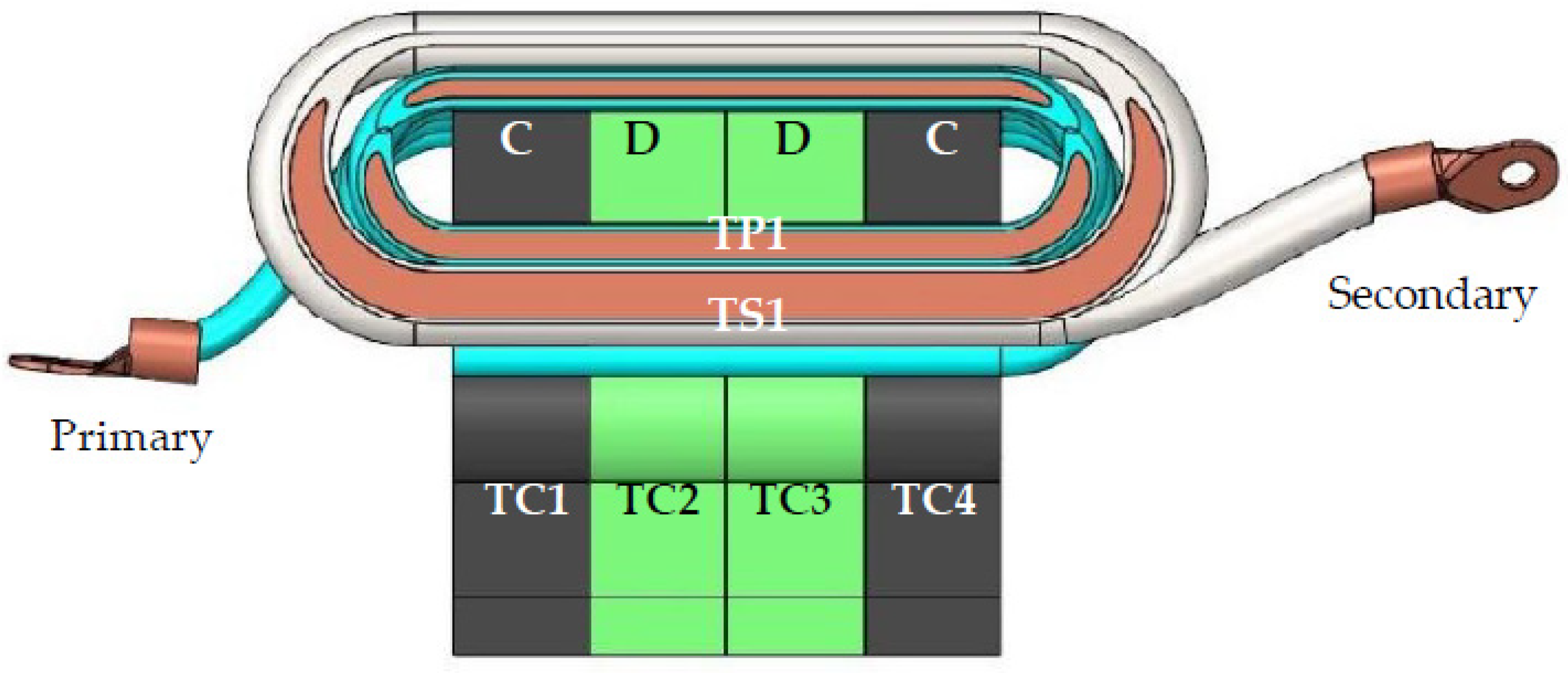
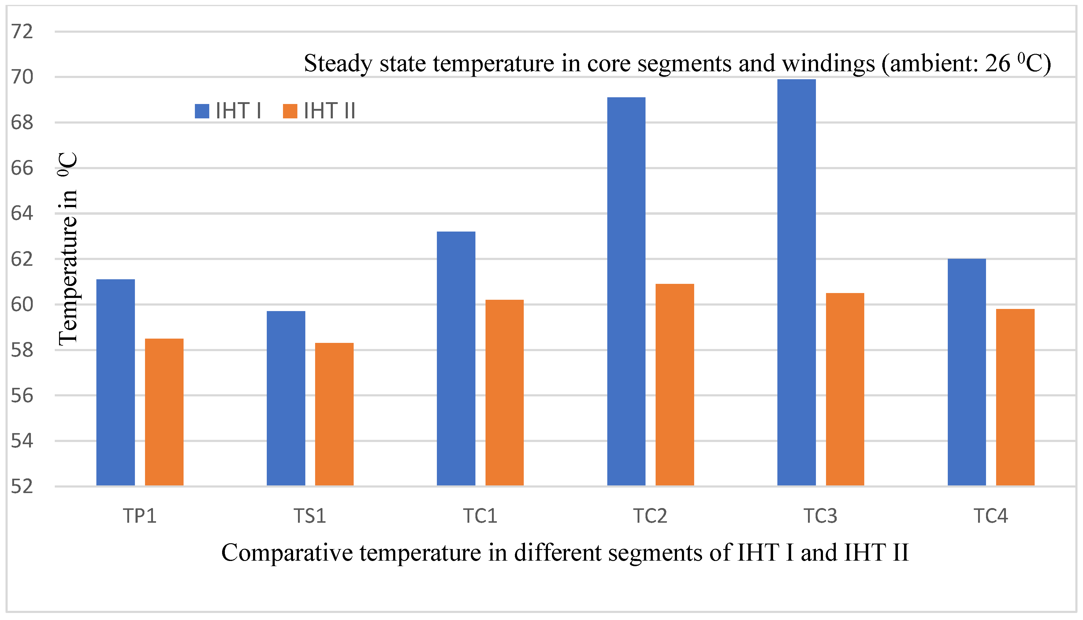
In order to gauge the gain of using the MCT, both IHT I and IHT II were put on a heat run test. The power drawn from the inverter was 35 kW (corresponding waveforms are shown in Figure 21b). IHTs were kept in open air under natural convection (shown in Figure 18). Each test was conducted until the steady state temperature in each core was attained. The ambient temperature was 26 °C. Using the noncontact type Fluke make 59 Mini IR and subsequently verified by the RTD thermometers at the end of the test, the temperature was recorded, as detailed in Figure 22, not only in each winding but also in each core segment. The measured hot spot temperature in different core and the windings of both the IHTs are shown in Figure 23. Due to the large value of K (see Table 4), the temperature distribution was found to be nearly uniform in each core segment. Moreover, compared to IHT I, temperature rise in each core of IHT II was reduced. The variation in temperature rise among different cores was also reduced. The temperature reading of internal cores with material D was much less when compared with that of IHT I. It essentially demonstrated that the power handling capacity of the MCT could be upgraded, and its power density could as well be increased.
5. Conclusions
The total power loss (i.e., core plus copper losses) in the majority of PETs would take place around a small core volume where the primary and secondary windings were overlaid. The surface area belonging to the rest of the core volume would remain exposed to the ambient environment. This article analyzed that the exposed surface area could be utilized effectively for heat transfer to the surrounding medium if the heat loss was easily channelized. The article proposed that a mixed-core configuration in the magnetic circuit could be used to achieve the goal. The idea was to replace the critical segment of the magnetic circuit having constrained heat conduction features by a geometrically compatible new core segment. The new segment would possess certain superior features, e.g., in core loss density, thermal conductivity, etc. To establish the compatibility of new core material, suitability factors were introduced for two different types of reluctance circuits. To validate the proposed idea, two transformers were built to cater two characteristically different applications. Initially, the magnetic compatibility of both the magnetic circuits under a worst-case operating condition were validated. Finally, both the transformers were put on prolonged load testing to comparatively validate their thermal performance. For both type of magnetic circuits, the superior thermal performance achieved during the heat run test validated the proposed idea. The reduced hot spot temperature in core and copper meant that the capacity rating of mixed-core transformer could be upgraded.
Funding
This research received no external funding and there is no APC involved for the article. The article is submitted on invitation.
Acknowledgments
The author thanks Vijay Lotekar, Vaibhav Arde, Mangesh Waman and Bhavna Rahate of Electronics Devices Pvt. Ltd. for assistance during experiments.
Conflicts of Interest
The author declares that there is no conflict of interest.
References
- Popović-Gerber, J.; Oliver, J.A.; Cordero, N.; Harder, T.; Cobos, J.A.; Hayes, M.; O’Mathuna, S.C.; Prem, E. Power electronics enabling efficient energy usage: Energy savings potential and technological challenges. IEEE Trans. Power Electrons 2012, 27, 2338–2353. [Google Scholar] [CrossRef]
- Hurley, W.G.; Wolfle, W.H.; Breslin, J.G. Optimized transformer design: Inclusive of high-frequency effects. IEEE Trans. Power Electrons 1998, 13, 651–659. [Google Scholar] [CrossRef]
- Mogorovic, M.; Dujic, D. Thermal modeling and experimental verification of an air cooled medium frequency transformer. In Proceedings of the 2017 19th European Conference on Power Electronics and Applications (EPE’17 ECCE Europe), Warsaw, Poland, 11–14 September 2017; pp. 1–9. [Google Scholar]
- Paul, A.K. ZVZCS SRI guides optimal use of copper and core for air-cooled nanocrystalline transformer for induction heating. IEEE Trans. Ind. Appl. 2020, 56, 970–978. [Google Scholar] [CrossRef]
- Ruiz, R.D.; Venegas, R.V.; Anaya, R.A.; Moreno, G.E.; Rodríguez, R.J. Design and prototyping medium frequency transformers featuring a nanocrystalline core for DC−DC converter. Energies 2018, 11, 2081. [Google Scholar] [CrossRef]
- Liu, J.; Sheng, L.; Shi, J.; Zhang, Z.; He, X. Design of high voltage, high power and high frequency transformer in LCC resonant converter. In Proceedings of the 2009 Twenty-Fourth Annual IEEE Applied Power Electronics Conference and Exposition, Washington, DC, USA, 15–19 February 2009; pp. 1034–1038. [Google Scholar]
- Shen, W.; Wang, F.; Boroyevich, D.; Tipton, C.W., IV. High-Density Nanocrystalline Core Transformer for High-Power High-Frequency Resonant Converter. IEEE Trans. Ind. Appl. 2008, 44, 213–222. [Google Scholar] [CrossRef]
- Yao, P.; Jiang, X.; Xue, P.; Li, S.; Lu, S.; Wang, F. Design optimization of medium-frequency transformer for DAB converters with DC bias capacity. IEEE J. Emerg. Sel. Top. Power Electron. 2021, 9, 5043–5054. [Google Scholar] [CrossRef]
- Shih, L.; Liu, Y.; Chiu, H. A novel hybrid mode control for a phase-shift full-bridge converter featuring high efficiency over a full-load range. IEEE Trans. Power Electron. 2019, 34, 2794–2804. [Google Scholar] [CrossRef]
- Costinett, D.; Seltzer, D.; Maksimovic, D.; Zane, R. Inherent volt-second balancing of magnetic devices in zero-voltage switched power converters. In Proceedings of the 2013 Twenty-Eighth Annual IEEE Applied Power Electronics Conference and Exposition (APEC), Long Beach, CA, USA, 17–21 March 2013; pp. 9–15. [Google Scholar] [CrossRef]
- Choi, J.M.; Byen, B.J.; Lee, Y.J.; Han, D.H.; Kho, H.S.; Choe, G.H. Design of leakage inductance in resonant DC−DC converter for electric vehicle charger. IEEE Trans. Magn. 2012, 48, 4417–4420. [Google Scholar] [CrossRef]
- Ram, B.S.; Paul, A.K.; Kulkarni, S.V. Soft magnetic materials and their applications in transformers. J. Magn. Magn. Mater. 2021, 537, 168210. [Google Scholar] [CrossRef]
- Kauder, T.; Hameyer, K. Performance factor comparison of nanocrystalline, amorphous and crystalline soft-magnetic materials for medium frequency applications. IEEE Trans. Magn. 2017, 53, 8401504. [Google Scholar] [CrossRef]
- Jimenez, H.O. AC resistance Evaluation of Foils, Round and Litz Conductors in Magnetic Components. Master’s Thesis, Chalmers University of Technology, Göteborg, Sweden, 2013. [Google Scholar]
- Morched, A.; Marti, L.; Ottevangers, J. A high frequency transformer model for the EMTP. IEEE Trans. Power Deliv. 1993, 8, 1615–1626. [Google Scholar] [CrossRef]
- Mu, M. High Frequency Magnetic Core Loss Study. Ph.D. Thesis, Virginia Polytechnic Institute and State University, Blacksburg, VA, USA, 2013. [Google Scholar]
- Muhlethaler, J.; Beila, J.; Kolar, J.W.; Ecklebe, A. Core losses under the DC bias condition based on Steinmetz parameters. IEEE Trans. Power Electron. 2012, 27, 953–963. [Google Scholar] [CrossRef]
- Rodriguez-Sotelo, D.; Rodriguez-Licea, M.A.; Araujo-Vargas, I.; Prado-Olivarez, J.; Barranco-Gutiérrez, A.I.; Perez-Pinal, F.J. Power losses models for magnetic cores: A review. Micromachines 2022, 13, 418. [Google Scholar] [CrossRef] [PubMed]
- Venkatachalam, K.; Sullivan, C.R.; Abdallah, T.; Tacca, H. Accurate prediction of ferrite core loss with nonsinusoidal waveforms using only Steinmetz parameters. In Proceedings of the 2002 IEEE Workshop on Computers in Power Electronics, 2002. Proceedings, Mayaguez, PR, USA, 3–4 June 2002; pp. 36–41. [Google Scholar] [CrossRef]
- Wang, Y.R. Modelling and Characterization of Losses in Nanocrystalline Cores. Ph.D. Thesis, University of Manchester, Manchester, UK, 2015. [Google Scholar]
- Bahamani, M. Design and Optimization Considerations of Medium-Frequency Power Transformer in High-Power DC−DC Applications. Ph.D. Thesis, Chalmers University of Technology, Gothenberg, Sweden, 2016. [Google Scholar]
- Bahmani, M.A.; Thiringer, T. Accurate evaluation of leakage inductance in high-frequency transformers using an improved frequency-dependent expression. IEEE Trans. Power Electron. 2015, 30, 5738–5745. [Google Scholar] [CrossRef]
- Hurley, W.G.; Gath, E.; Breslin, J.G. Optimizing the AC resistance of multilayer transformer windings with arbitrary current waveforms. IEEE Trans. Power Electron. 2000, 15, 369–376. [Google Scholar] [CrossRef]
- Zhao, H.; Eldeeb, H.H.; Zhang, Y.; Zhang, D.; Zhan, Y.; Xu, G.; Mohammed, O.A. An improved core loss model of ferromagnetic materials considering high-frequency and nonsinusoidal supply. IEEE Trans. Ind. Appl. 2021, 57, 4336–4346. [Google Scholar] [CrossRef]
- Li, Z.; Yao, K.; Li, D.; Ni, X.; Lu, Z. Core loss analysis of Finemet type nanocrystalline alloy ribbon with different thickness. Prog. Nat. Sci. Mater. Int. 2017, 27, 588–592. [Google Scholar] [CrossRef]
- Zhou, Y.; Qi, B.; Zheng, M.; Cong, B. A novel DC bias suppression strategy for single-phase full-bridge DC−DC arc welding converter. Electronics 2021, 10, 428. [Google Scholar] [CrossRef]
- Kohama, T.; Tokimatsu, S.; Shimamori, H. Elimination of magnetic saturation due to fast dynamic response in DC−DC converter. In Proceedings of the INTELEC 2009—31st International Telecommunications Energy Conference, Incheon, Korea, 18–22 October 2009; pp. 1–6. [Google Scholar] [CrossRef]
- Paul, A.K. Choice of control function in magnetically-coupled full bridge DC−DC power controller for arc welding: A practical approach. J. Power Electron. Devices Compon. 2022, 2, 100005. [Google Scholar] [CrossRef]
- Paul, A.K. Emulating full load testing of air-cooled nanocrystalline IHT at zero power. IEEE J. Emerg. Sel. Top. Ind. Electron. 2022, 3, 725–732. [Google Scholar] [CrossRef]
- Wang, H.; Blaabjerg, F. Power electronics reliability: State of the art and outlook. IEEE J. Emerg. Sel. Top. Power Electron. 2021, 9, 6476–6493. [Google Scholar] [CrossRef]
- Nikolov, G.T.; Valchev, V.C. Nanocrystalline magnetic materials vs ferrites in power electronics. Procedia Earth Planetory Sci. 2009, 1, 1357–1361. [Google Scholar] [CrossRef]
- Hilal, A.; Raulet, M.A.; Martin, C.; Sixdenier, F. A comparative study: Dynamic and thermal behavior of nanocrystalline and powder magnetic materials in a power converter application. J. Electron. Mater. 2015, 44, 3768–3776. [Google Scholar] [CrossRef]
- Paul, A.K. Robust product design using SOSM for control of shielded metal arc welding (SMAW) process. IEEE Trans. Ind. Electron. 2016, 63, 3717–3724. [Google Scholar] [CrossRef]
- Malesani, L.; Mattavelli, P.; Rossetto, L.; Tenti, P.; Marin, W.; Pollmann, A. Electronic welder high frequency resonant converter. IEEE Trans. Ind. Appl. 1995, 31, 273–279. [Google Scholar] [CrossRef]
- Ruiz-Robles, D.; Moreno-Goytia, E.L.; Venegas-Rebollar, V.; Salgado-Herrera, N.M. Power density maximization in medium frequency transformers by using their maximum flux density for DC–DC converters. Electronics 2020, 9, 470. [Google Scholar] [CrossRef]
- Paul, A.K. Structured protection measures for better use of nanocrystalline cores in air-cooled medium-frequency transformer for induction heating. IEEE Trans. Ind. Electron. 2021, 68, 3898–3905. [Google Scholar] [CrossRef]
- Meziane, B.; Zeroug, H. Improved efficiency determination for a PLL-controlled series resonant inverter for induction metal surface hardening. In Proceedings of the 2015 IEEE Industry Applications Society Annual Meeting, Addison, TX, USA, 18–22 October 2015; pp. 1–8. [Google Scholar]
- Plesca, A. Considerations about maximum temperature of toroidal transformers in steady-state conditions. J. Adv. Therm. Sci. Res. 2020, 7, 22–29. [Google Scholar] [CrossRef]
- Purushothaman, S.; de Leon, F. Heat-transfer model for toroidal transformers. IEEE Trans. Power Deliv. 2012, 27, 813–820. [Google Scholar] [CrossRef]
- Lefevre, G.; Chazal, H.; Ferrieux, J.P.; Roudet, J. Application of Dovvell method for nanocrystalline toroid high frequency transformers. In Proceedings of the 2004 IEEE 35th Annual Power Electronics Specialists Conference (IEEE Cat. No.04CH37551), Aachen, Germany, 20–25 June 2004; Volume 2, pp. 899–904. [Google Scholar] [CrossRef]
- Petkov, R. Optimum design of a high-power, high-frequency transformer. IEEE Trans. Power Electron. 1996, 11, 33–42. [Google Scholar] [CrossRef]
- Jaritz, M.; Biela, J. Analytical model for the thermal resistance of windings consisting of solid or litz wire. In Proceedings of the 2013 15th European Conference on Power Electronics and Applications (EPE), Lille, France, 2–6 September 2013; pp. 1–10. [Google Scholar] [CrossRef]
- Kącki, M.; Rylko, M.S.; Hayes, J.G.; Sullivan, C.R. Magnetic material selection for EMI filters. In Proceedings of the 2017 IEEE Energy Conversion Congress and Exposition (ECCE), Cincinnati, OH, USA, 1–5 October 2017; pp. 2350–2356. [Google Scholar] [CrossRef]
Figure 1.
Arrangement of a basic power electronics system.

Figure 2.
Typical power transformer using EE or UU cores.

Figure 3.
Popular arrangements of PET where magnetic circuit is configured in (a) series reluctance circuit model and (b) parallel reluctance circuit model.
Figure 3.
Popular arrangements of PET where magnetic circuit is configured in (a) series reluctance circuit model and (b) parallel reluctance circuit model.

Figure 4.
Typical power circuit of full-bridge DC−DC converter.

Figure 5.
The power circuit for a series resonant induction heating controller.

Figure 6.
(a) Symmetrical half of PET of Figure 3a and (b) equivalent thermal circuit to remove heat loss.
Figure 6.
(a) Symmetrical half of PET of Figure 3a and (b) equivalent thermal circuit to remove heat loss.


Figure 8.
Behavior of relative permeability of soft magnetic materials vs. temperature [43].
Figure 8.
Behavior of relative permeability of soft magnetic materials vs. temperature [43].

Figure 9.
Permeability vs. flux density of competitive nanocrystalline cores have similar drooping characteristics.
Figure 9.
Permeability vs. flux density of competitive nanocrystalline cores have similar drooping characteristics.

Figure 10.
At a particular frequency the core loss density in nanocrystalline cores is minimum.

Figure 11.
Mixed-core assembly is for better use of the (a) electrical circuit of PET, i.e., the windings, and (b) magnetic circuit or the core assembly.
Figure 11.
Mixed-core assembly is for better use of the (a) electrical circuit of PET, i.e., the windings, and (b) magnetic circuit or the core assembly.

Figure 12.
Mixed-core transformers for FBDC where windings are overlaid on the core of material type (a) A for PET A and (b) B for PET B.
Figure 12.
Mixed-core transformers for FBDC where windings are overlaid on the core of material type (a) A for PET A and (b) B for PET B.

Figure 13.
Prototype of a 4.5 kW DC−DC converter for performance testing of PET A and PET B.

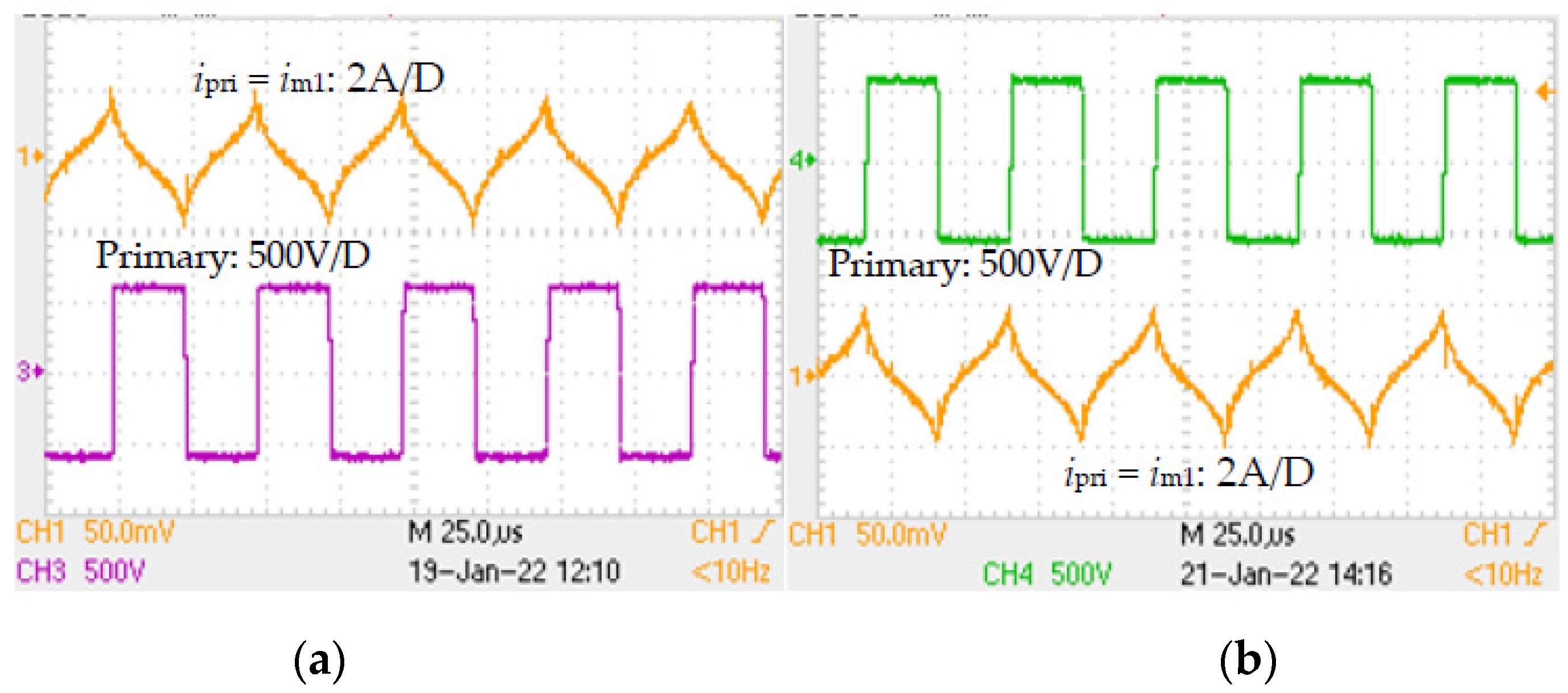
Figure 14.
At zero secondary current, even in nonlinear operating zone of B-H curve (Bm = 0.325 T), the behavior of the magnetic circuit of (a) PET A was similar to that of (b) PET B.
Figure 14.
At zero secondary current, even in nonlinear operating zone of B-H curve (Bm = 0.325 T), the behavior of the magnetic circuit of (a) PET A was similar to that of (b) PET B.

Figure 15.
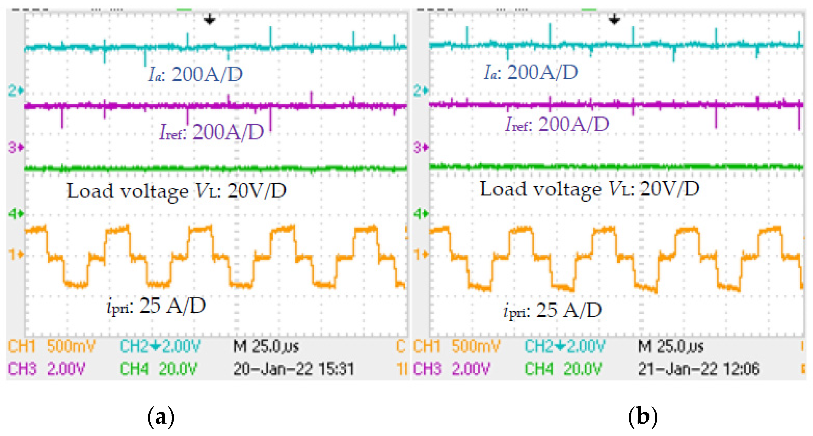
Waveforms of FBDC controller when 200 A was drawn by the load and, in that loading condition, the magnetic circuit was loaded with Bm at 0.207 T, for both (a) PET A and (b) PET B.
Figure 15.
Waveforms of FBDC controller when 200 A was drawn by the load and, in that loading condition, the magnetic circuit was loaded with Bm at 0.207 T, for both (a) PET A and (b) PET B.

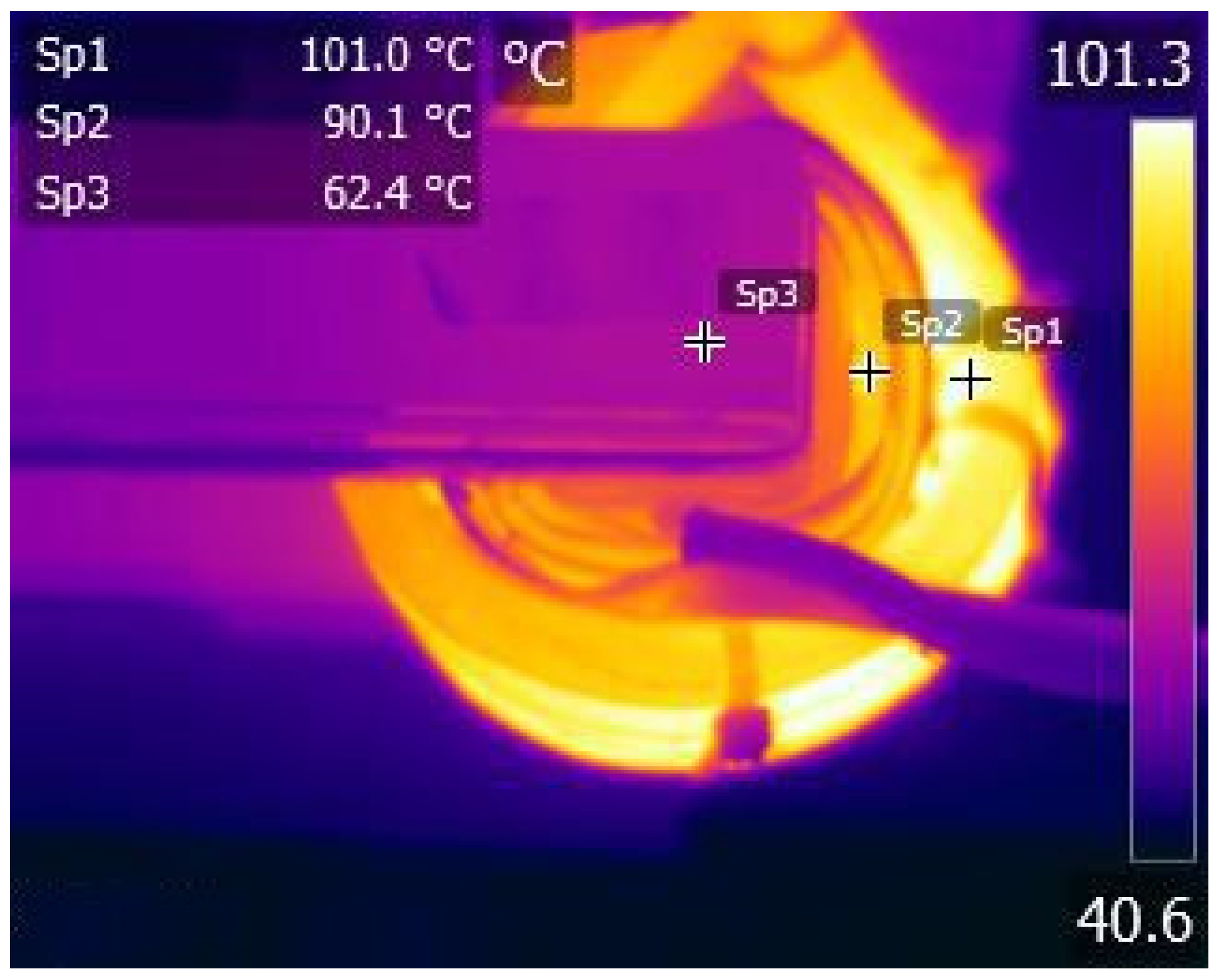
Figure 16.
Temperature distribution of PET A using thermal camera (ambient temp.: 33 °C).

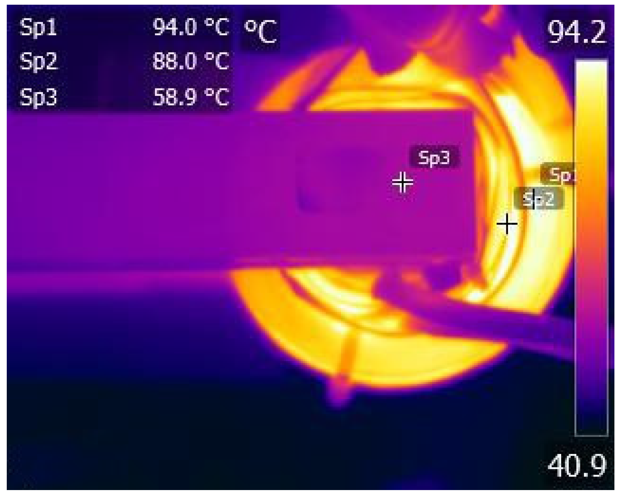
Figure 17.
Temperature distribution of PET B using thermal camera (ambient temp.: 33 °C).

Figure 18.
40 kW induction heating controller for testing of IHTI and IHT II.

Figure 19.
Two 40 kW, 15 kHz transformers: (a) IHT I with original set of C cores and (b) IHT II with mixed-core configuration (C-D-D-C).
Figure 19.
Two 40 kW, 15 kHz transformers: (a) IHT I with original set of C cores and (b) IHT II with mixed-core configuration (C-D-D-C).

Figure 20.
Magnetic compatibility of C and D cores was verified through similar voltage readings in search coils wound on the respective cores, when (a) the secondary of IHT II was kept open, and (b) the DC blocking capacitor Cdc of 100 µF was added (shown in Figure 5) but the coil L4 was not loaded.

Figure 21.
(a) The magnetic compatibility of IHT II was also verified when the coil head was loaded. (b) Waveforms of different variables of the inverter when the IHT was loaded at 35 kW while delivering power to a section of pipe through the coil head L4.
Figure 21.
(a) The magnetic compatibility of IHT II was also verified when the coil head was loaded. (b) Waveforms of different variables of the inverter when the IHT was loaded at 35 kW while delivering power to a section of pipe through the coil head L4.

Figure 22.
Sectional view of 40 kW transformer in mixed-core (core C and D) configuration.

Figure 23.
Compared to IHT I, the steady state temperature in different parts of IHT II was not only reduced, there was increased uniformity in maximum temperature in various parts of the mixed-core transformer.
Figure 23.
Compared to IHT I, the steady state temperature in different parts of IHT II was not only reduced, there was increased uniformity in maximum temperature in various parts of the mixed-core transformer.


Table 1.
Comparison on basic parameters of a few soft magnetic materials for transformer.
| Core Material | Si-Steel | Ferrite | Amorphous | Nanocrystalline |
|---|---|---|---|---|
| Thermal conductivity K, °C/mK | 18.6 | ≤5 | 10 | 10 |
| Loss density (W/kg) at 0.1 T, 20 kHz | 20.0 | 1.9 | 4.7 | 0.9 |
| Loss density (kW/m3) at 0.1 T, 20 kHz | 150 | 9.1 | 34 | 6.6 |
| Relative permeability µr | 900 | 2200 | 15,000 | 15,000 |
| Maximum operating temperature, °C | 150 | 100 | 150 | 120–150 |
| Saturation flux density Bsat at 25 °C | 1.8 | 4.9 | 1.56 | 1.23 |
| Curie Temperature, °C | 770 | 230 | 415 | 570 |
Table 2.
Properties of ferrite cores type A and type B.
| Core Material | Ferrite Core A | Ferrite Core B | ||
|---|---|---|---|---|
| At temperature | 25 °C | 100 °C | 25 °C | 100 °C |
| Initial permeability | 2500 | 2200 | ||
| Bsat, T | 0.47 | 0.38 | 0.49 | 0.39 |
| Curie temp., °C | >230 | >210 | ||
| Pc @ 0.2 T, 25 kHz, kW/m3 | 130 | 65 | 130 | 57 |
| Pc @ 0.1 T, 100 kHz, kW/m3 | 135 | 65 | 140 | 50 |
| Thermal conductivity K, W/mK | ≤4.3 | 5.0 | ||
Table 3.
Measured hot spot temperature (°C) in core and windings (Ambient temp.: 28 °C).
| Transformer | Primary | Secondary | Temperature of Core (°C) |
|---|---|---|---|
| PET A | 86.9 | 92.8 | Core A: 61.7 |
| PET B | 83.6 | 89.3 | Core B: 57.3 |
Table 4.
Parameters of core C (black) and D (green).
| Parameter | Core C | Core D |
|---|---|---|
| Bsat at 25 °C (130 °C), T | 1.2 (1.18) | 1.25 (1.21) |
| Initial permeability μr | >300 k | >300 k |
| KS1, α, β | 0.94, 1.4364, 1.638 | 0.22, 1.608, 1.681 |
| Value of μr at Bm = 1 T | >12 k | >12 k |
| Ribbon thickness, μm | 30 | 22 |
| Area of each core, cm2 | 5.25 | 5.62 |
| Mean length of core, cm | 29.8 | 29.8 |
| Pc @0.2 T, 20 kHz, W/kg | 4.98 | 1.82 |
| Pc @0.6 T, 10 kHz, W/kg | 11.2 | 3.78 |
| Th. conductivity K, W/mK | 10 | 10 |
Table 5.
Operating parameters of IHT and core loss data.
| IHT I | IHT II | |
|---|---|---|
| Delivered power, kW | 35 | |
| Input voltage to inverter at full load, V | 450 | |
| Inverter frequency at full load, kHz | 12.5 | |
| Core area, cm2 | 21 | 21.74 |
| Value of Bm in C, T | 0.535 | 0.517 |
| Value of Bm in D, T | - | 0.517 |
| Core loss density in each of C, W/kg | 12.7 | 12.0 |
| Core loss density in each of D, W/kg | - | 4.21 |
Publisher’s Note: MDPI stays neutral with regard to jurisdictional claims in published maps and institutional affiliations. |
© 2022 by the author. Licensee MDPI, Basel, Switzerland. This article is an open access article distributed under the terms and conditions of the Creative Commons Attribution (CC BY) license (https://creativecommons.org/licenses/by/4.0/).
Share and Cite
MDPI and ACS Style
Paul, A.K. Practical Study of Mixed-Core High Frequency Power Transformer. Magnetism 2022, 2, 306-327. https://doi.org/10.3390/magnetism2030022
AMA Style
Paul AK. Practical Study of Mixed-Core High Frequency Power Transformer. Magnetism. 2022; 2(3):306-327. https://doi.org/10.3390/magnetism2030022
Chicago/Turabian StylePaul, Arun Kumar. 2022. "Practical Study of Mixed-Core High Frequency Power Transformer" Magnetism 2, no. 3: 306-327. https://doi.org/10.3390/magnetism2030022