1. Introduction
Olefins are crucial building blocks for the petrochemical industry, serving as raw materials for the production of various products such as plastics, synthetic fibers, detergents, solvents, and other chemicals. The demand for olefins is significant due to their versatile nature and wide range of applications in numerous industries [
1]. Olefins are a class of hydrocarbons, primarily composed of carbon and hydrogen atoms, with at least one carbon–carbon double bond. The most common olefins are ethylene (C
2H
4) and propylene (C
3H
6). Olefins are frequently produced in Steam Cracking and Fluid Catalytic Cracking installations. In FCC, heavy petroleum feedstocks are injected into a catalytic cracking unit, where they are mixed with a catalyst. The feedstock–catalyst mixture is then subjected to high temperatures and moderate pressures. The catalyst aids in breaking down the large hydrocarbon molecules into smaller fragments, including olefins like Propylene and Ethylene.
Ethylene and Propylene polymerization reactions occur at high temperatures. It has been shown that the highest yields of butylene and propane have been obtained at 630 °C, and the highest yield of propylene and total light olefins has been observed at 660 °C [
1].
These reactions demand heat removal as quickly as possible to control the reactor temperature and to avoid “hot spots” in the regenerator or localized reactions (and to avoid creep rupture of the regenerator’s steel cladding) [
2,
3].
In the Fluid Catalytic Cracking process, the regenerator is responsible for burning off the coke that has accumulated on the catalyst particles during the cracking reaction. To control the temperature in the regenerator and ensure efficient coke combustion, various cooling methods are employed. There are some common methods used to cool the FCC regenerator, as follows:
- (1)
Air/Oxygen introduction: Air or oxygen is introduced into the regenerator to support the combustion process. This helps to burn off the coke and generate heat. The flow rate of air or oxygen can be adjusted to control the temperature and ensure efficient coke combustion.
- (2)
Steam or water injection: Steam or water can be injected into the regenerator as a method of cooling. This is achieved by evaporating the injected water or steam, which absorbs heat from the regenerator and reduces the temperature. The injected steam or water can also help to dilute the flue gas and control the oxygen concentration, aiding in the combustion process.
- (3)
Internal refractory lining: The regenerator vessel is often lined with refractory materials, which have high heat resistance. These refractory linings help to minimize heat transfer to the vessel shell, reducing the overall temperature. They also protect the vessel from excessive heat and prolong its lifespan.
- (4)
Catalyst cooler: The FCC catalyst cooler helps to regulate the regenerator temperature and ensures the continuous and efficient operation of the fluid catalytic cracking process in petroleum refineries [
4]. The catalyst cooler is basically a vertical shell-and-tube heat exchanger attached to the regenerator [
5]. The cooler extracts high quality heat from the catalyst in the regenerator to produce high pressure steam. The hot catalyst enters the cooler at a high temperature, and as it passes through the heat exchangers, it comes into contact with a cooling medium, such as air or water, which absorbs the excess heat and lowers the catalyst’s temperature. The cooled catalyst is then directed back into the FCC reactor to continue the cracking process [
6].
- (5)
Catalyst Withdrawal: Some FCC units utilize a catalyst (such as zeolite) withdrawal system that removes a portion of the catalyst from the regenerator before it reaches excessively high temperatures. This helps to control increases in temperature and it prevents damage to the catalyst [
7].
These cooling methods are implemented in combination or individually, depending on the specific design of the FCC unit and the requirements of the refinery. The aim is to maintain optimal operating conditions, maximize coke combustion efficiency, and ensure the long-term integrity of the regenerator equipment.
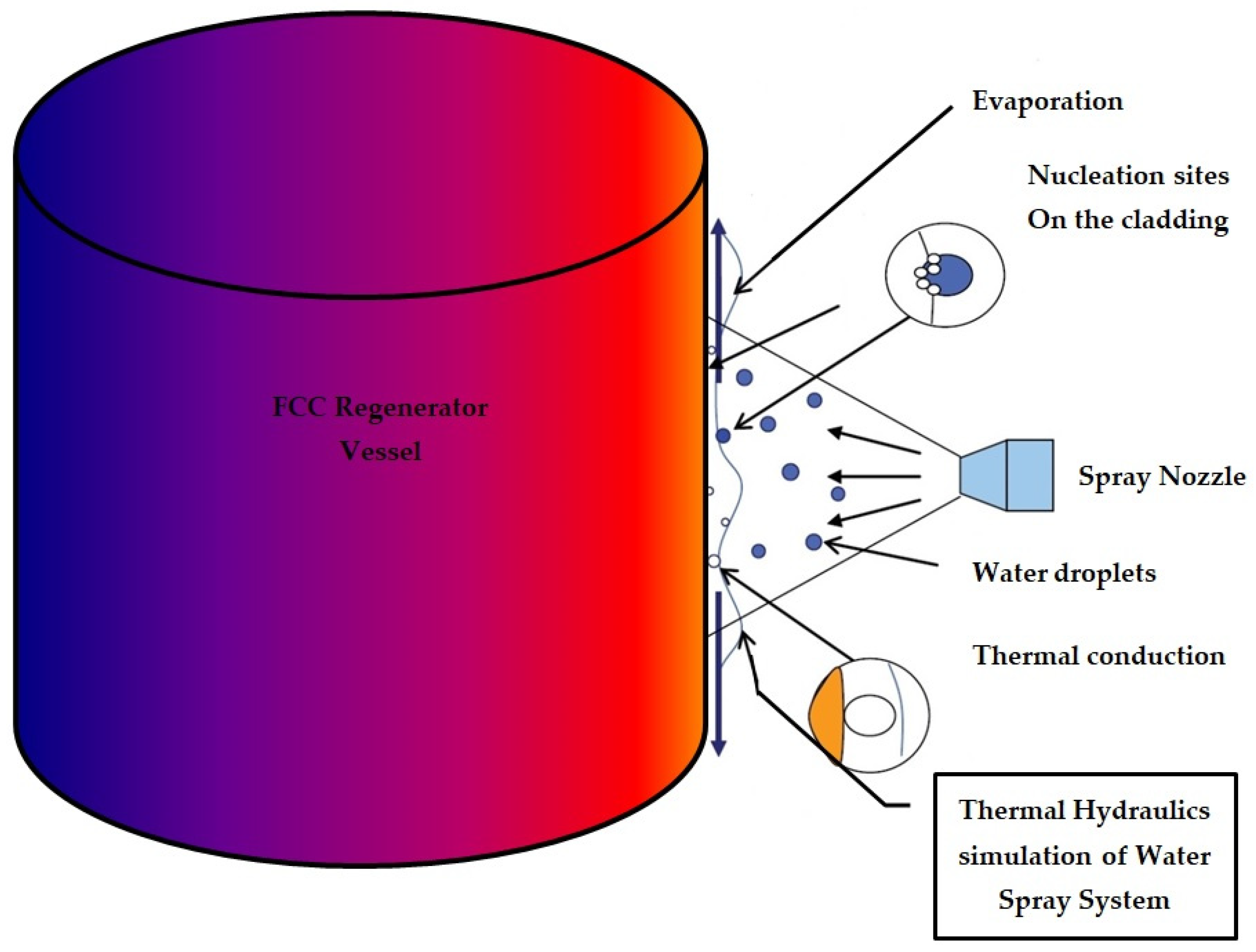
The cooling of the regenerator’s surface can be achieved by impinging water droplets (spray), ejected from a spray nozzle. Spray cooling can provide uniform cooling and it can handle high heat fluxes in both a single phase and two phases [
8].
1.1. Spray Cooling Heat Transfer Mechansims
The principle behind water spray cooling is the evaporation of water, which absorbs heat from the surface being cooled. When water droplets are sprayed onto a hot surface, they absorb the thermal energy and undergo phase change, transitioning from a liquid to a vapor state. This phase change process requires energy, and it draws heat away from the surface, thus lowering its temperature. The increase in heat transfer is influenced by the surface area which is covered by a liquid film. Thus, it is recommended to cover larger heated areas with a water film [
9]. Goldstein et al. [
10] have shown a significant increase in the heat-transfer coefficient with a two-phase spray flow over a flat plate. They have neglected the effects of liquid film agitation and evaporation. Scherberg et al. [
11] experimentally studied liquid–gas spray flows over an elliptical cylinder and a circular cylinder. They have also studied liquid–gas spray flows over a composite geometry containing a forward semi-circular cylindrical section and a downward rectangular section. These geometries have a common capture area. Yin et al. [
12] introduced the state of spray cooling for the heat dissipation of electronics by reviewing the available experimental studies.
1.2. Literature Survey Concerning Numerical Simulations of Spray Cooling
Anisiuba et al. [
13] applied a four-step simulation approach in order to simulate air-mist spray cooling. This simulation produced turbulence, it caused the two fluids in the nozzle to mix, droplet formation occurred, and impingement heat transfer occurred. The numerical results obtained for the droplet aligned well with the experimental results. Jafari [
14] applied the STAR-CCM+ CFD code. This code solved the main transport equations, as follows: continuity, momentum, and energy equations. This was achieved using the Lagrangian–Eulerian solver, which is capable of simulating droplets, as well as thin fluid film. Good agreement has been observed for the heat transfer coefficient (HTC) values in cases involving spray impact and fluid film formation over a flat solid surface. The effect of mass flux and the spray Reynolds number on spray behavior has been studied. Salman [
15] developed a three dimensional (3D) multi-phase numerical model in order to simulate the spray cooling heat transfer processes. STAR-CCM+, 12.04.010-R8 software has been applied as a CFD solver. Lagrangian–Eulerian and Eulerian–Eulerian modeling approaches have been adopted in order to simulate the fluid flow and heat transfer during spray cooling. The comparison between the numerical results and experimental results showed a satisfactory agreement. The maximum absolute deviation has been less than 15%. Da Silva Kranzfeld et al. proposed general conditions for the simulation of an aerosol jet in the air based on the Eulerian approach. The effect of the particle diameter on dispersion has been investigated [
16].
1.3. Scope and Novelty of This Paper
This work examines the thermal hydraulics simulation of a water spray system for cooling a Fluid Catalytic Cracking Regenerator. It is the first time that a Fire Dynamics Simulator and COMSOL codes have been employed in order to predict the heat flux that is removed from the FCC Regenerator cladding using spray cooling.
Figure 1 shows the regenerator shell cooling mechanism.
2. Materials and Methods
2.1. Critical Heat Flux (CHF) of Spray Cooling
Spray cooling is limited by Critical Heat Flux, which is defined as the maximal heat flux in the boiling heat transfer, as shown in
Figure 2 [
17]. The most serious problem is that the boiling limitation can be directly related to the physical ‘drying out’ of the heated steel due to the suddenly inefficient heat transfer that occurs through a vapor film covering the surface [
18]. This may lead to the regenerator cladding melting and to hydrocarbon leaking.
The results of investigations into heat transfer rates using pool boiling are usually plotted on a graph of surface heat flux, against a heated wall surface temperature [
19]. The component parts of the boiling curve (see
Figure 2) represent each region.
- (a)
Natural convection (region OA), where heat is removed via natural convection from the cladding surface to the bulk. The liquid water starts to evaporate.
- (b)
The onset of nucleate boiling (ONB), where the cladding is superheated so that it is able to cause vapor nucleation at the heating surface.
- (c)
The nucleate boiling region (AB), where vapor nucleation occurs on the cladding surface. It starts with a few bubbles at low heat fluxes, then, the vapor structure becomes more intense as the heat flux is increased. The bubbles begin to coalesce, and finally, at high heat fluxes, vapor patches are formed close to the cladding surface (Annular flow).
- (d)
The critical heat flux (CHF or point B) marks the maximal value of nucleate boiling heat flux (see
Figure 2). At this point, there is a restriction on the liquid supply to the heating surface.
- (e)
The transition boiling region (DE) is characterized by the existence of an unstable vapor blanket over the heating surface. Large amounts of vapor may be released.
- (f)
The film boiling region (CD), where a stable vapor film forms and covers the entire heating surface. The heat is transferred via convection and conduction through the vapor film. Thermal radiation heat transfer increases with the cladding surface temperature.
2.2. Thermophysical Properties of the Steel
The thermophysical properties of the steel alloy, AISI4340, are shown in
Table 1 [
20].
2.3. Fire Dynamic Simulation Modeling of Water Spray Cooling
The Fire Dynamics Simulator is a computational fluid dynamics (CFD) model developed by the National Institute of Standards and Technology (NIST) in the United States [
21,
22]. It is a powerful software tool used to simulate the behavior of fire and smoke within a three-dimensional environment. FDS is widely used in fire research, fire safety engineering, fire investigations, and extinguishing fires using sprinklers and suppression by water. The key features of Fire Dynamics Simulator are as follows:
- (a)
Computational Fluid Dynamics: FDS is based on the principles of fluid dynamics, heat transfer, combustion, and spray cooling. It uses computational algorithms to model and simulate the movement of air, heat, and combustion products during a fire event.
- (b)
Geometry and Meshing: Users can create complex 3D geometries of buildings or structures using various software tools, and they can import them into FDS. The geometry is typically represented using a computational grid (mesh) that allows the simulation of fire dynamics within the defined space.
- (c)
Heating and Evaporation of Droplets: Droplets are represented either as discrete particles propelled by the carrying gas, or as rectangular blocks that collectively form a thin liquid film on solid objects. They are individually tracked as Lagrangian particles. The mass and heat transfer coefficients are different.
- (d)
Combustion and Heat Transfer: The software models the combustion process, taking into account the chemical reactions and heat transfer between fire and surrounding objects.
- (e)
Absorption and Scattering of Thermal Radiation by Water Droplets: The thermal radiation attenuation of liquid droplets should be considered, especially for water mist systems. Liquid droplets attenuate thermal radiation via a combination of absorption and scattering. The radiative Transfer Equation (RTE), which includes these interactions, should be solved for both the accurate prediction of the radiation field and for the droplet energy balance.
- (f)
Validation and Verification: FDS has been extensively validated against experimental data to ensure its accuracy and reliability in predicting fire behavior in various scenarios.
- (g)
Fire Safety Engineering: FDS is used to evaluate the effectiveness of fire protection measures, such as sprinkler systems, smoke control systems, and fire-resistant materials in buildings.
2.4. FDS Modelling of the Spray Cooling System
The geometrical model of the spray cooling system is shown in
Figure 3.
The height of the model is 4.0 m. The width and the length of the model are 2 m and 2 m, respectively. The mesh size of the spray cooling system is 64,000 cells. The left surface of the model is cooled using water spray nozzle.
Table 2 shows the thermocouple and concentration locations inside the spray cooling system (the coordinate system center is located at the bottom plate—see
Figure 3).
Initial condition—The initial temperature of the steel cladding is 800 °C. The initial temperature and species concentration in the surrounding air and the pressure are as follows [
23]:
Boundary Condition—the water spray nozzle injects water droplets into the atmosphere. The volumetric flow rate is 100 L/min. The injected cone angle is 15°. The injected droplet velocity i: 21.2 m/s. The surrounding conditions are as follows [
23]:
2.5. Calculation of the Convective Heat Transfer Coefficient of the Cladding Surface
The water mass flux is calculated using the following equation:
where
denotes the water density in kg/m
3 and
denotes the water volumetric flow rate in m
3/s. It has been assumed that the volumetric flow rate of the injected water droplets is 100 L/min. r denotes the radial distance between the water nozzle and the cladding surface in m.
is the cone angle in rad. The cone spray angle is 15°. The water mass flux is about 0.9 kg/(m
2·s).
The Nusselt number is calculated using the following equation [
24,
25]:
where Re denotes the Reynolds number. This term is calculated using the following equation [
25]:
Here,
D denotes the diameter of the covered surface. This term is calculated using Equation (4):
Thus,
D = 0.1 m. μ is the water dynamic viscosity. The convective heat transfer coefficient is calculated using the following equation [
25]:
The convective heat transfer is obtained using Equation (4) and is 23,050 w/(m2·s).
3. Results
This section shows the numerical results for the water vapor mole fraction and temperature near the steel wall.
3.1. Computational Model Validation
The calculated temperatures obtained using FDS software have been validated against COMSOL numerical results and the study by Cebo-Rudnicka and Buczek [
23]. For the framework of this research, a thermal model was developed using COMSOL multi-physics software. It was assumed that the heat transfer convective coefficient is 20,000 w/(m
2 K). This value is very similar to the convective coefficient obtained using the Karwa empirical correlation (see Equation (5)) [
25] and by Jafari [
14].
Figure 4 shows the calculated surface of the steel cladding as a function of time, obtained using COMSOL.
The surface temperatures obtained using FDS and COMSOL codes are similar. The convective heat transfer coefficient obtained using the study by Cebo-Rudnicka and Buczek [
26] is 20,000 for water spray mass flux of 1 kg/(m
2 K) (see
Figure 5).
As is evident from
Figure 5, the numerical results obtained in this work are similar to the results obtained in [
26].
3.2. Grid Sensitivity Study Results
A grid sensitivity study was conducted on the FDS model. Computational models were developed, consisting of 40,000 and 64,000 cells. Numerical integrations were conducted over the time in order to calculate the average temperatures. The differences between the average temperatures obtained by applying different computational grids are provided in
Table 3.
The difference between these four average temperatures, calculated by applying different grids, is less than 7.4%.
3.3. Numerical Model Results
Numerical simulations were conducted for two cases. The first case was conducted at a distance of 0.5 m, between the nozzle injector and regenerator cladding wall, and the second case was conducted at a distance of 0.2 m.
Figure 6 shows the calculated temperature field for the second case (the mesh size of the spray cooling system contains 64,000 cells).
Figure 6 demonstrates the cooling capabilities of spray cooling. It clearly shows that the upper thermocouples (TC4 and TC5) are exposed to spray cooling. Thus, the temperature readings of these thermocouples remain low compared with the other thermocouples.
3.3.1. Results Obtained for the First Case
Figure 7 provides the transient thermal response of the five thermocouples (TC1–TC5). It is evident from
Figure 7 that sharp decreases occur in the temperature readings at relatively short time intervals.
3.3.2. Results Obtained for the Second Case
Figure 8 provides the transient thermal response of the five thermocouples (TC1–TC5).
From
Figure 7 and
Figure 8, it is evident that there is a reduction in the calculated temperatures in the second case. The water spray system manages to cool the steel wall more effectively as the water spray system approaches the steel cladding. The thermocouple, TC5, is cooled with the direct water impingement. Thus, its temperature readings are lower than the TC3 readings (see
Figure 7).
Figure 9 shows the transient response of the water vapor mass fraction obtained using the five sensors.
It is evident from
Figure 9 that the vapor mass fraction readings of sensor no. 4 and 5 are larger than the other three water vapor mass fractions. This physical phenomenon is caused by significant water evaporation. Water evaporation is very significant at relatively short time intervals. In accordance with
Figure 8, during shorter time intervals, the surface temperatures are greater than the atmospheric water boiling temperature.
4. Discussion
Ethylene and Propylene polymerization reactions are highly exothermic. The reaction demands heat removal as quickly as possible in order to control the reactor temperature and avoid “hot spots” in the regenerator or in localized reactions (and to avoid the creep rupturing of the regenerator’s steel cladding).
Water spray cooling is a technique used to reduce the temperature of a surface or an environment by spraying water onto it. It is commonly employed in various industrial processes, power plants, data centers, and even for personal cooling purposes. The principle behind water spray cooling is the evaporation of water, which absorbs heat from the surface being cooled. When water droplets are sprayed onto a hot surface, they absorb the thermal energy and undergo phase change, transitioning from a liquid to a vapor state. This phase change process requires energy, and it draws heat away from the surface, thus lowering its temperature.
Water spray cooling can be achieved through various methods, including the following:
Direct Spray Cooling: In this method, water is sprayed directly onto the surface that needs to be cooled. The water droplets come into direct contact with the hot surface, and evaporation takes place, resulting in cooling.
Indirect Spray Cooling: In indirect spray cooling, water is sprayed into the surrounding environment or onto a medium, such as a heat exchanger or cooling coil. The hot air or fluid passing through the medium comes into contact with the sprayed water, and heat transfer occurs through evaporation.
Water spray cooling offers several advantages, as follows:
- (1)
Efficient Heat Transfer: Evaporative cooling using water spray can effectively transfer large amounts of heat due to the high latent heat of water vapor.
- (2)
Cost-Effective: Water is readily available and relatively inexpensive compared with other cooling methods.
- (3)
Environmental Benefits: Water spray cooling is considered environmentally friendly as it does not require the use of refrigerants or other chemicals that may be harmful to the environment.
- (4)
Flexibility: Water spray cooling can be easily applied to various surfaces and systems, making it a versatile cooling technique.
- (5)
However, there are also some considerations when using water spray cooling, as follows:
- (6)
Water Consumption: It is essential to manage water usage and avoid excessive waste when employing water spray cooling systems.
- (7)
Corrosion and Scaling: Depending on the quality of the water and the materials involved, there may be a risk of corrosion or scaling on the cooled surfaces or equipment.
- (8)
Maintenance: Water spray systems require regular maintenance to ensure proper functioning, including cleaning nozzles, checking for blockages, and monitoring water quality.
Overall, water spray cooling is an effective and widely used technique for cooling applications, offering efficient heat transfer and environmental benefits. This paper deals with the design of a regenerator spray cooling system. A CFD simulation was conducted in order to perform an optimization of the spray mass flux. Numerical simulations were conducted for two cases. The first case was conducted at a distance of 0.5 m, and the second case was conducted at a distance of 0.2 m. It was found that a decrease in the calculated temperatures of the second case occurred. It has been shown that the water spray system manages to cool the steel wall more effectively as the water spray system approaches the cladding wall. Regarding the framework of this research, a thermal model was developed using COMSOL Multiphysics software. It was assumed that the heat transfer convective coefficient is 20,000 w/(m2 K). A grid sensitivity study was conducted on the FDS model. Computational models were developed, consisting of 40,000 and 64,000 cells. Numerical integrations were conducted over time in order to calculate the average temperatures. The difference between these four average temperatures, calculated by applying different grids, is less than 7.4%.
The calculated surface temperatures and heat transfer convective coefficient were validated successfully against COMSOL numerical results and previous research.


