
Investigation of Dynamic Behavior of Ultra-Large Cold-Water Pipes for Ocean Thermal Energy Conversion
 ,
,
Abstract
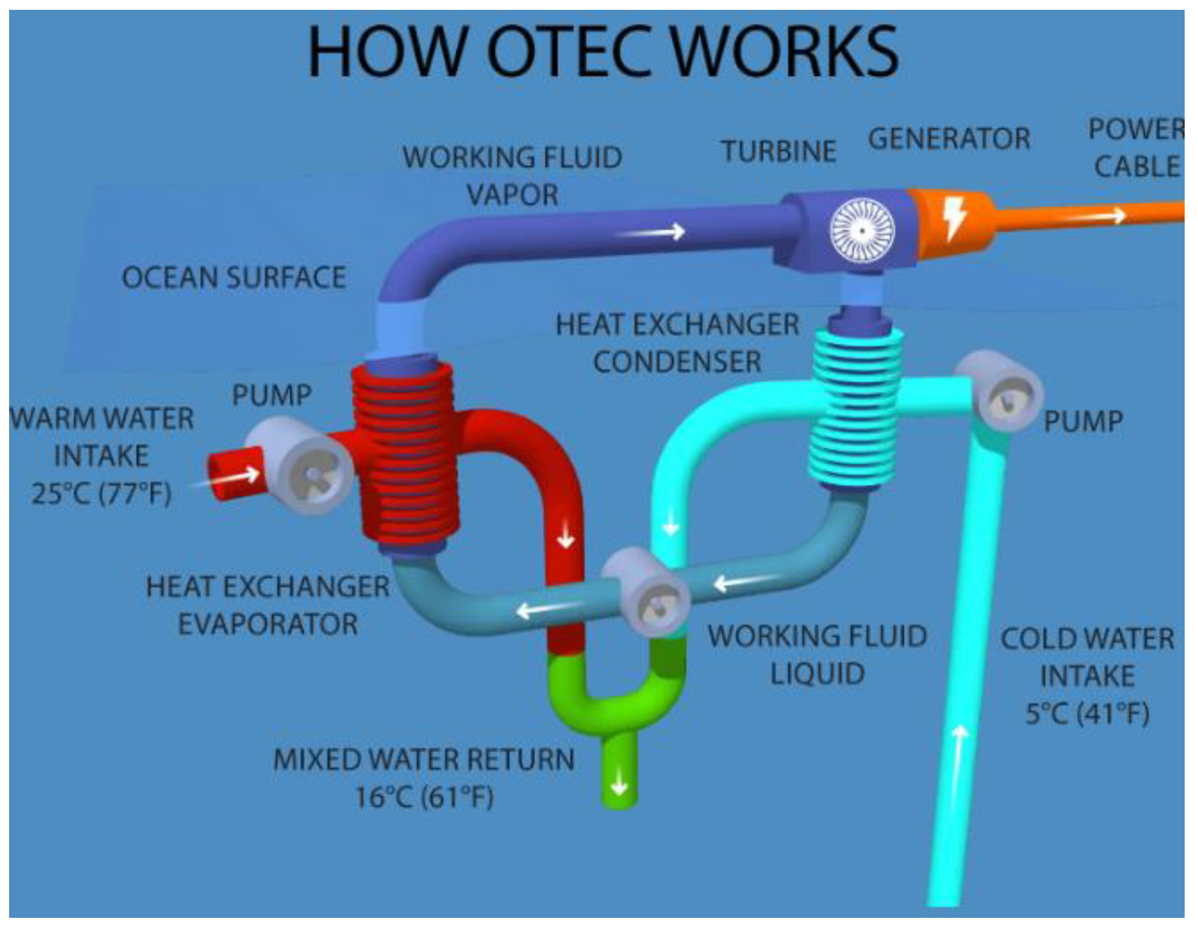
:1. Introduction
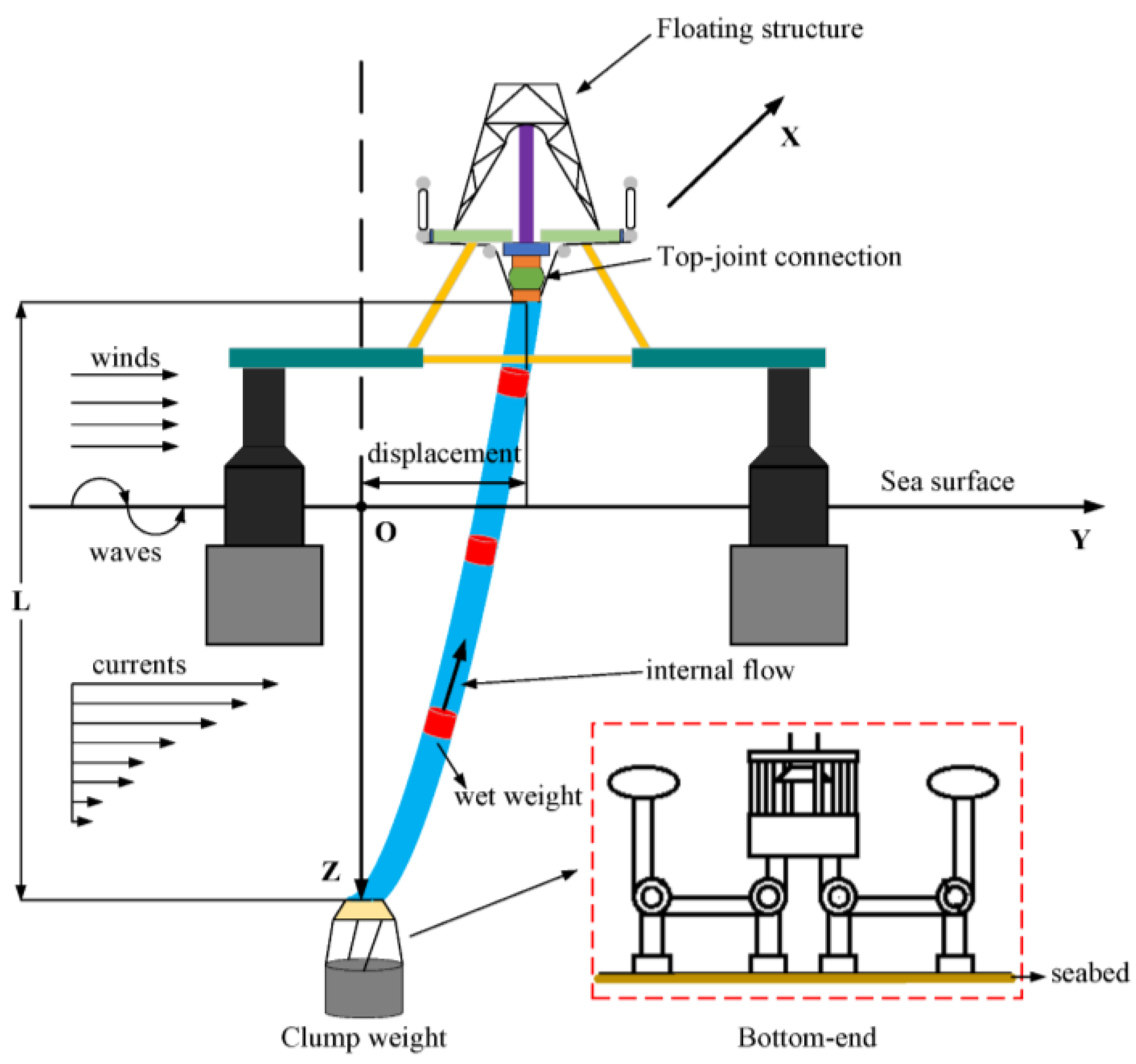
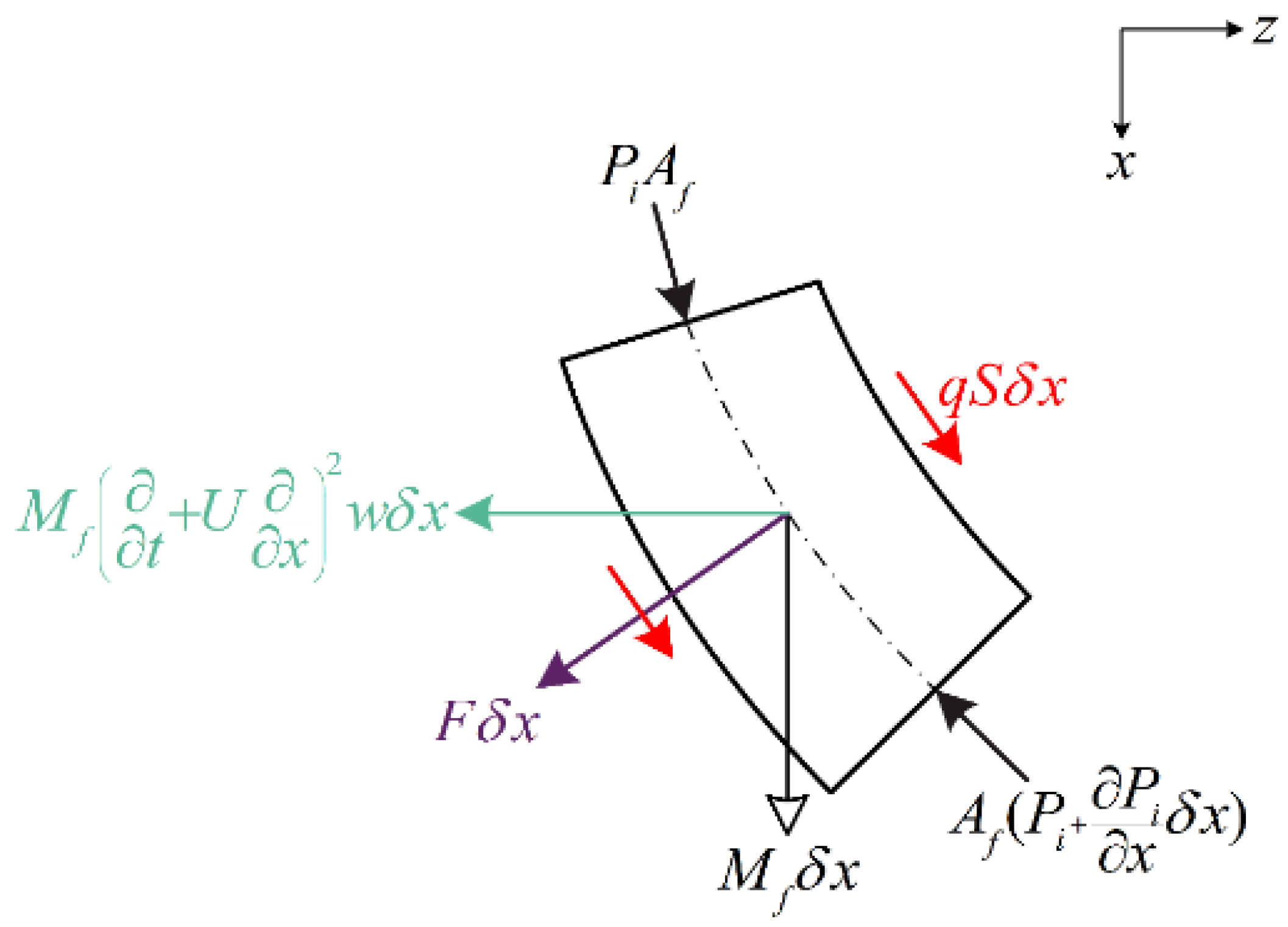
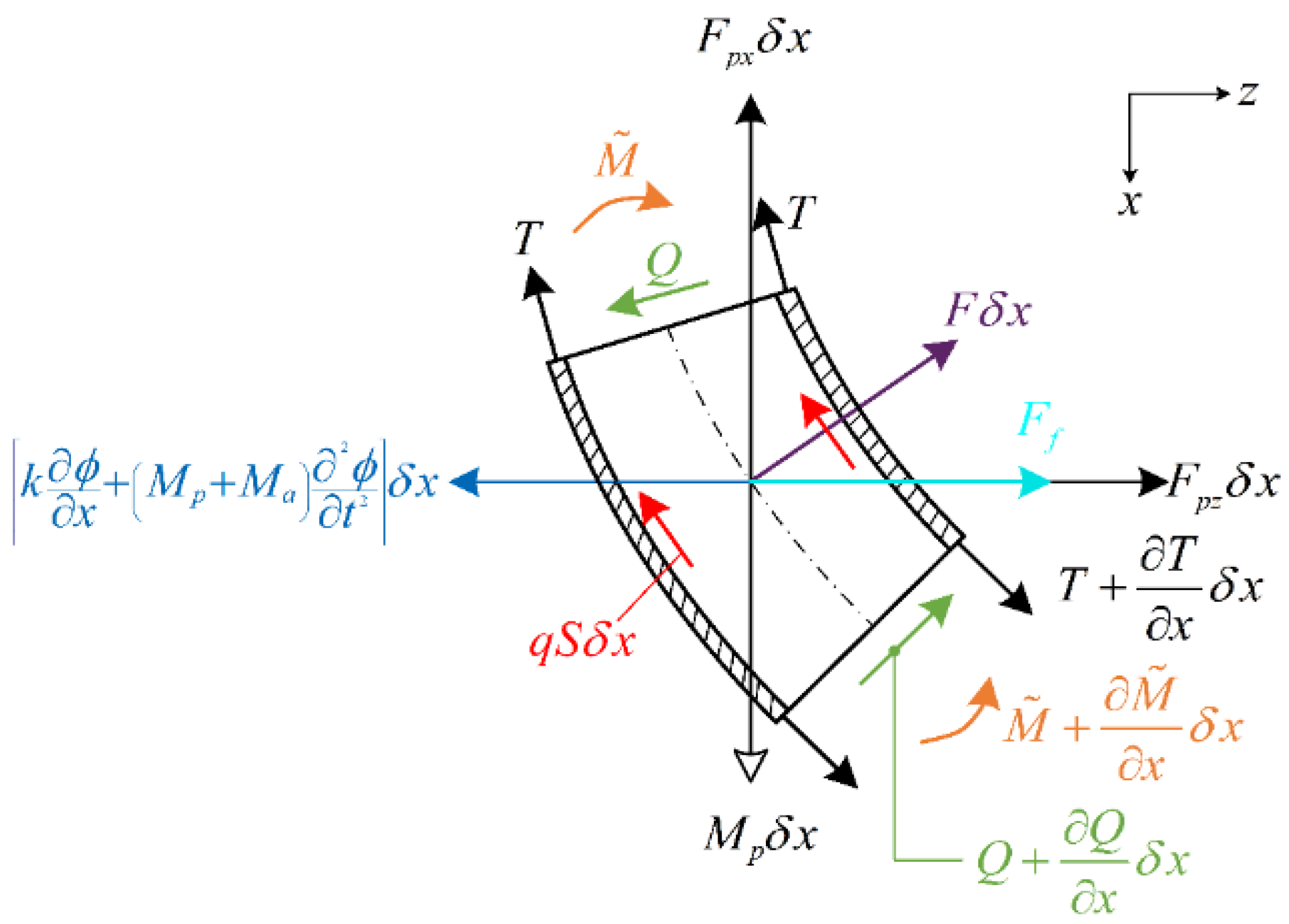
2. Analytical Simulation
3. Results and Discussion
3.1. Parameter Sensitivity Analysis
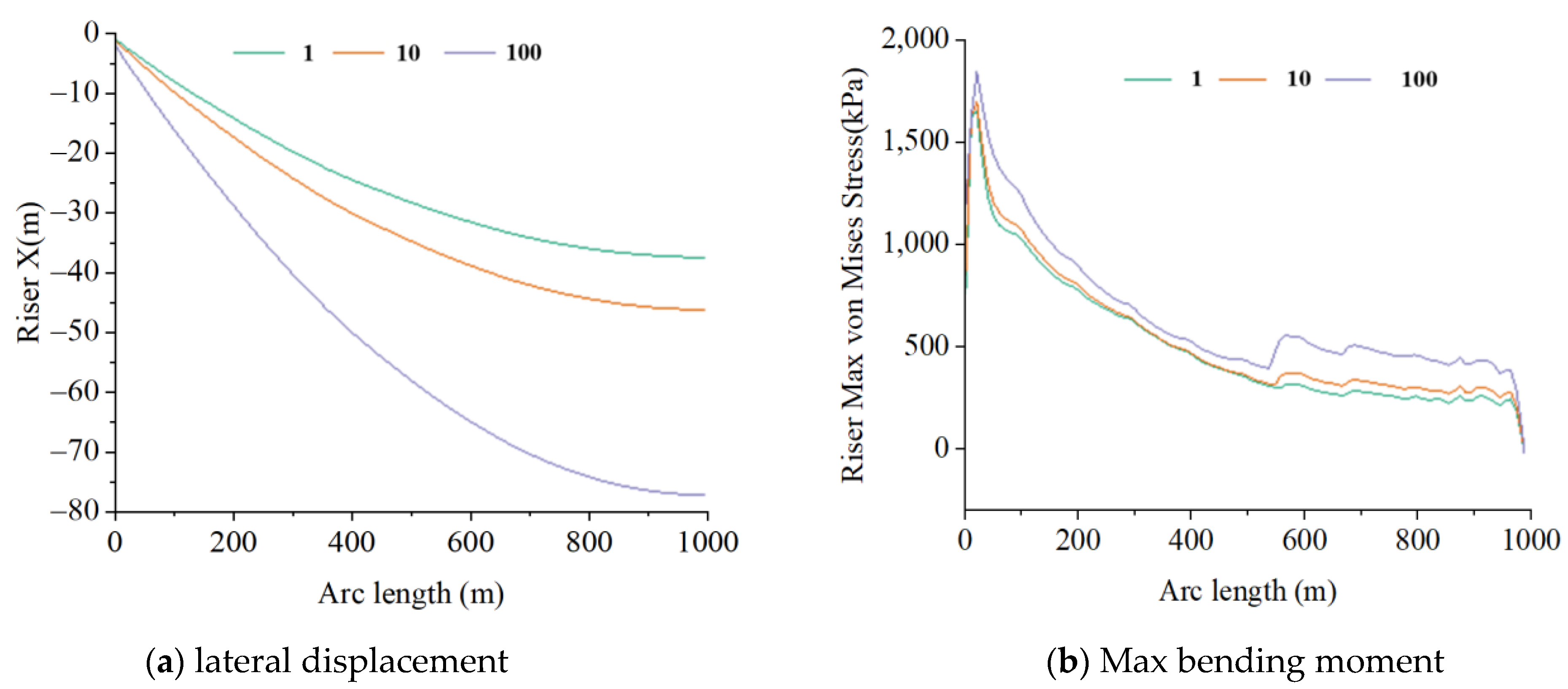
3.1.1. Effects of Waves
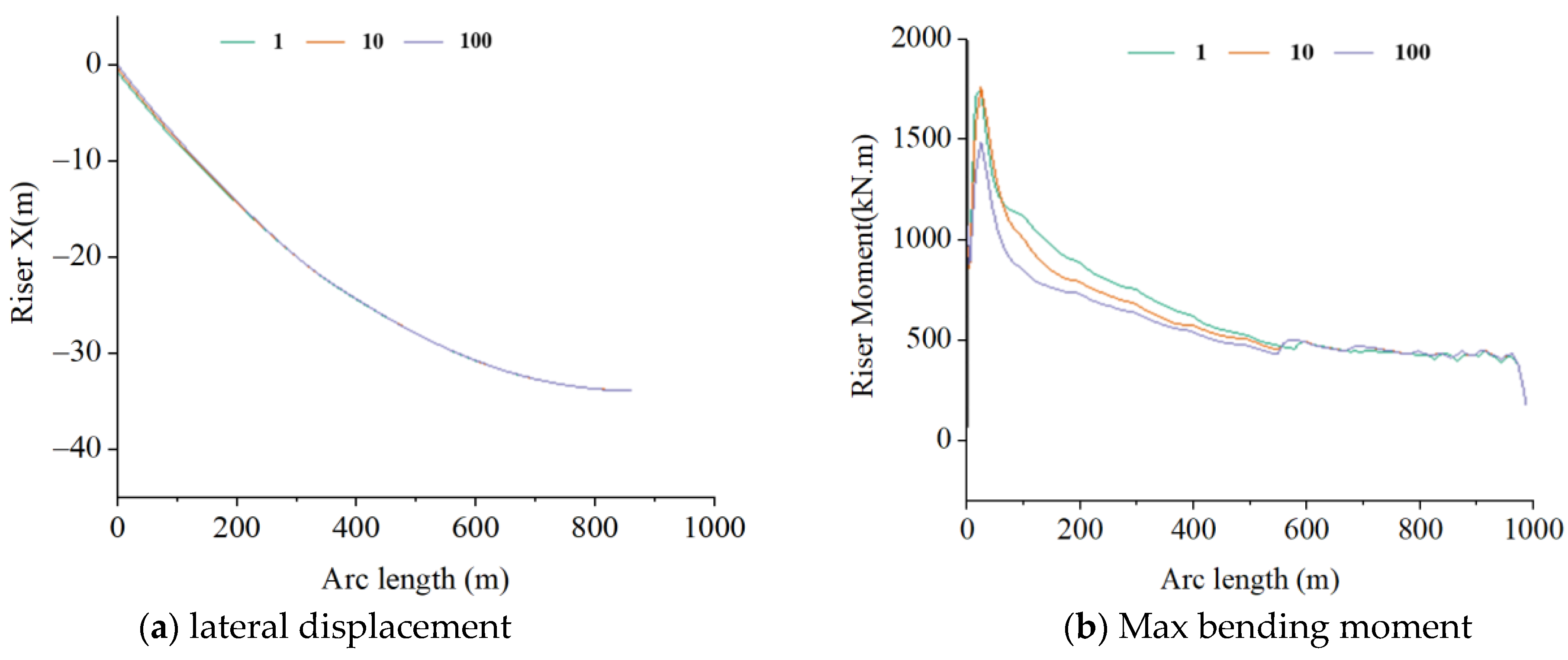
3.1.2. Effects of the Clump Weight
3.1.3. Effects of Internal Flow Velocity
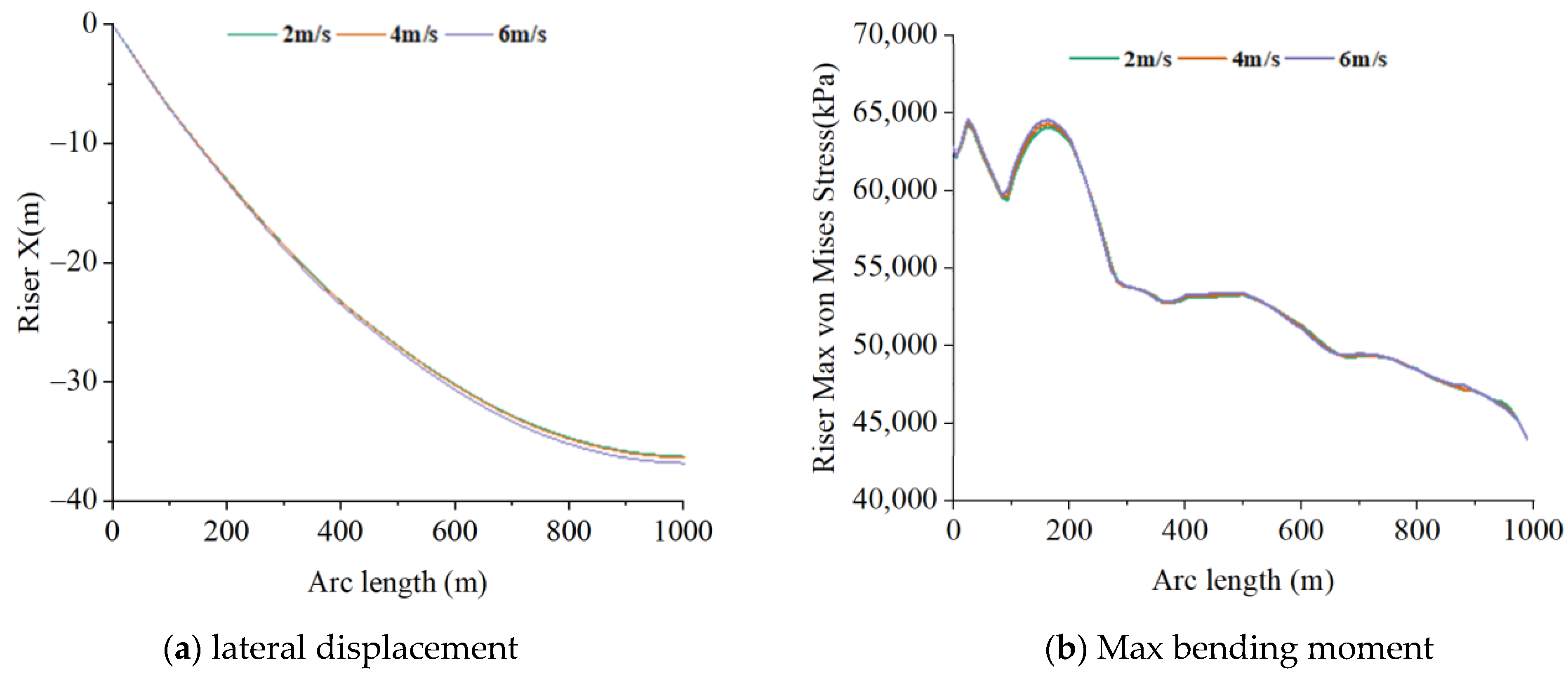
3.1.4. Effects of Current Velocity
3.2. Orthogonal Analysis of Key Parameters
3.2.1. Analysis of Orthogonal Experiments
3.2.2. Simulation Data Analysis
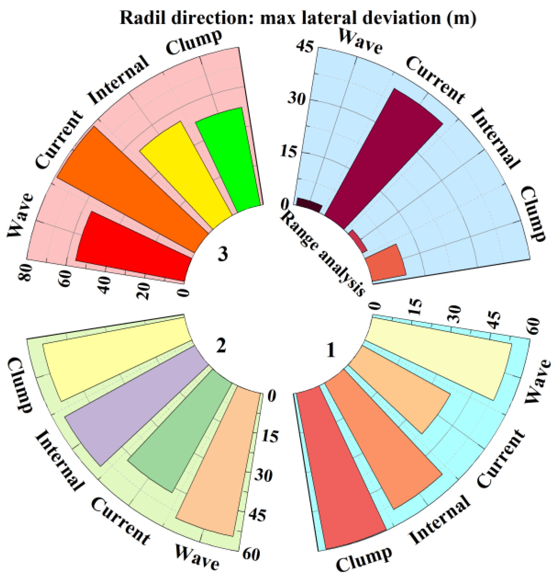
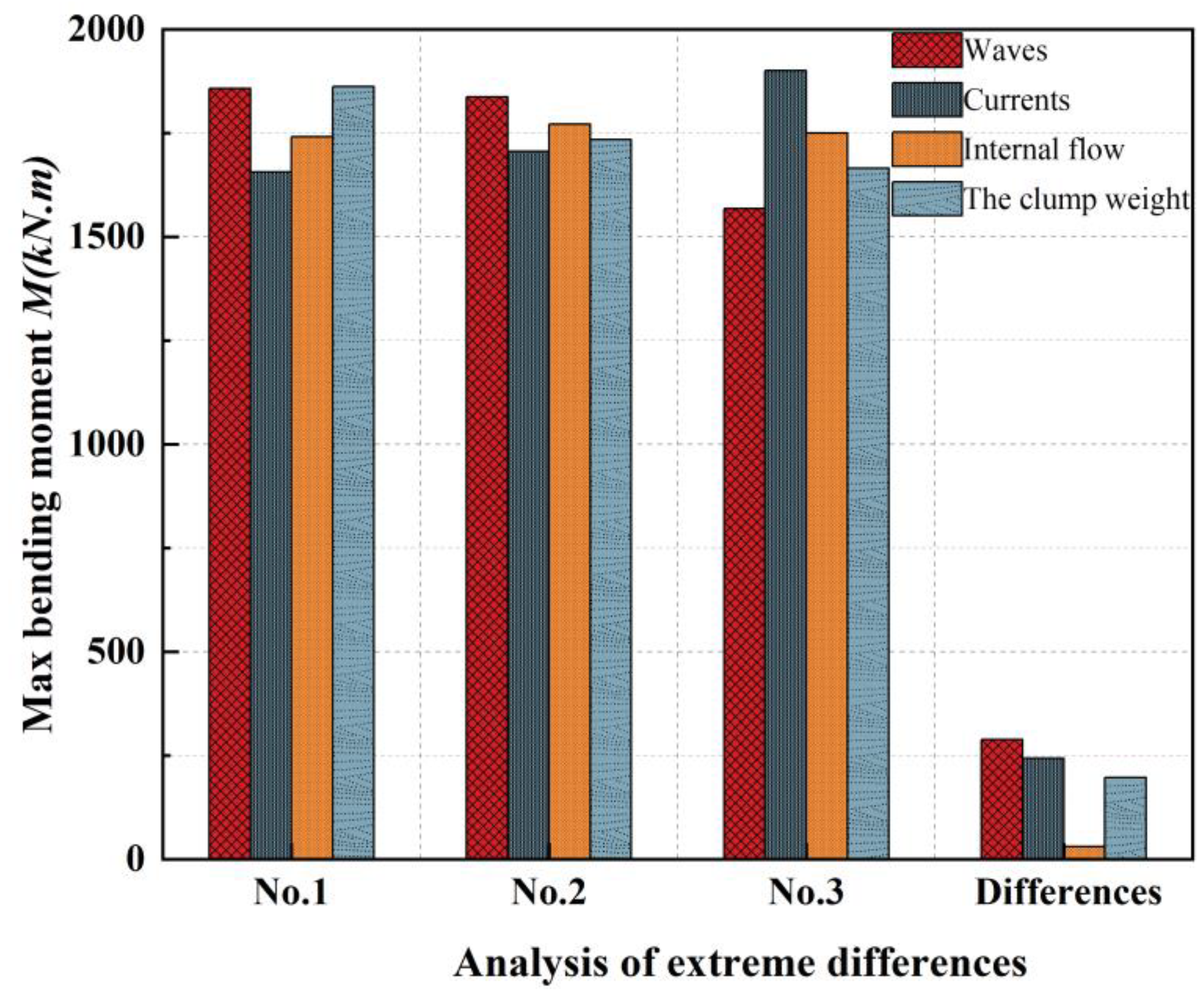
3.2.3. Extremum Difference Analysis
4. Conclusions
Author Contributions
Funding
Data Availability Statement
Acknowledgments
Conflicts of Interest
References
- Makai Ocean Engineering. Ocean Thermal Energy Conversion [EB/OL]. Available online: https://www.makai.com/ocean-thermal-energyconversion (accessed on 14 June 2023).
- Herrera, J.; Sierra, S.; Ibeas, A. Ocean thermal energy conversion and other uses of deep-sea water: A review. J. Mar. Sci. Eng. 2021, 9, 356. [Google Scholar] [CrossRef]
- Adiputra, R.; Utsunomiya, T. Stability based approach to design cold-water pipe (CWP) for ocean thermal energy conversion (OTEC). Appl. Ocean Res. 2019, 92, 101921. [Google Scholar] [CrossRef]
- Adiputra, R.; Utsunomiya, T. Linear vs non-linear analysis on self-induced vibration of OTEC cold water pipe due to internal flow. Appl. Ocean Res. 2021, 110, 102610. [Google Scholar] [CrossRef]
- Xiang, S.; Cao, P.; Erwin, R.; Kibbee, S. OTEC Cold Water Pipe Global Dynamic Design for Ship-Shaped Vessels. Volume 8: Ocean Renewable Energy. In Proceedings of the ASME 2013 32nd International Conference on Ocean, Offshore and Arctic Engineering, Nantes, France, 9–14 June 2013. [Google Scholar]
- Kuiper, G.L.; Metrikine, A.V. Dynamic stability of a submerged, free-hanging riser conveying fluid. J. Sound Vib. 2005, 280, 1051–1065. [Google Scholar] [CrossRef]
- Halkyard, J.; Sheikh, R.; Marinho, T.; Shi, S.; Ascari, M. Current Developments in the Validation of Numerical Methods for Predicting the Responses of an Ocean Thermal Energy Conversion (OTEC) System Cold Water Pipe. In Proceedings of the ASME 2014 33rd International Conference on Ocean, Offshore and Arctic Engineering, San Francisco, CA, USA, 8–13 June 2014. [Google Scholar]
- Shi, S.; Halkyard, J.; Kurup, N.; Jiang, L. Coupled Analysis Approach in OTEC System Design. In Proceedings of the ASME 2012 31st International Conference on Ocean, Offshore and Arctic Engineering, Rio de Janeiro, Brazil, 1–6 July 2012. [Google Scholar]
- Lockheed Martin. NAVFAC Ocean Thermal Energy Conversion (OTEC) Project; Naval Facilities Engineering Command: Port Hueneme, CA, USA, 2011. [Google Scholar]
- Thirugnana, S.T.; Jaafar, A.B.; Rajoo, S.; Azmi, A.A.; Karthikeyan, H.J.; Yasunaga, T.; Nakaoka, T.; Kamyab, H.; Chelliapan, S.; Ikegami, Y. Performance Analysis of a 10 MW Ocean Thermal Energy Conversion Plant Using Rankine Cycle in Malaysia. Sustainability 2023, 15, 3777. [Google Scholar] [CrossRef]
- Aitken, J. XIV. An account of some experiments on rigidity produced by centrifugal force. Lond. Edinb. Dublin Philos. Mag. J. Sci. 1878, 5, 81–105. [Google Scholar] [CrossRef]
- Bourriéres, F. Sur un Phénomène D’oscillation Auto-Entretenue en Mécanique des Fluides Reels; Blondel la Rougery: Gauthier-Villars, Switzerland, 1939. [Google Scholar]
- Housner, G.W. Bending Vibrations of a Pipe Line Containing Flowing Fluid. ASME J. Appl. Mech. 1952, 19, 205–208. [Google Scholar] [CrossRef]
- Gregory, R.W.; Paidoussis, M.P. Unstable oscillation of tubular cantilevers conveying fluid. I. Theory. Proc. R. Soc. (Lond.) A 1966, 293, 512–527. [Google Scholar]
- Gregory, R.W.; Paidoussis, M.P. Unstable oscillation of tubular cantilevers conveying fluid. II. Experiments. Proc. R. Soc. (Lond.) A 1966, 293, 528–542. [Google Scholar]
- Brooke Benjamin, T. Dynamics of a system of articulated pipes conveying fluid. I. Theory. Proc. R. Socicty (Lond.) A 1961, 261, 457–486. [Google Scholar]
- Wu, M.C.; Lou, J.Y.K. Effects of rigidity and internal flow on marine riser dynamics. Appl. Ocean Res. 1991, 13, 235–244. [Google Scholar] [CrossRef]
- Guo, H.Y.; Wang, S.Q.; Wu, J.N.; Liu, D.F. Dynamic Characteristics of Marine Risers Conveying Fluid. China Ocean Eng. 2000, 14, 153–160. [Google Scholar]
- Li, X.M.; Guo, H.Y.; Meng, F.S. Effect of internal flow on the dynamic behavior of top tensioned riser. J. Ship Mech. 2010, 14, 1021–1030. [Google Scholar]
- Jung, D.; Chung, J. In-plane and out-of-plane motions of an extensible semi-circular pipe conveying fluid. J. Sound Vib. 2008, 311, 408–420. [Google Scholar] [CrossRef]
- Ghayesh, M.H.; Païdoussis, M.P.; Modarres-Sadeghi, Y. Three-dimensional dynamics of a fluid-conveying cantilevered pipe fitted with an additional spring support and an end-mass. J. Sound Vib. 2011, 330, 2869–2899. [Google Scholar] [CrossRef]
- Łuczko, J.; Czerwiński, A. Parametric vibrations of flexible hoses excited by a pulsating fluid flow, Part I: Modelling, solution method and simulation. J. Fluids Struct. 2015, 55, 155–173. [Google Scholar] [CrossRef]
- Łuczko, J.; Czerwiński, A. Nonlinear three-dimensional dynamics of flexible pipes conveying fluids. J. Fluids Struct. 2017, 70, 235–260. [Google Scholar] [CrossRef]
- Misra, A.K.; Paidoussism, P.; Van, K.S. On the dynamics of curved pipes transporting fluid, part I: Inextensible theory. J. Fluids Struct. 1998, 2, 221–244. [Google Scholar] [CrossRef]
- Misra, A.K.; Paidoussism, P.; Van, K.S. On the dynamics of curved pipes transporting fluid, part II: Extensible theory. J. Fluids Struct. 1998, 2, 245–261. [Google Scholar] [CrossRef]
- Patel, M.H.; Seyed, F.B. Review of flexible riser modelling and analysis techniques. Eng. Struct. 1995, 17, 293–304. [Google Scholar] [CrossRef]
- Zare, K.; Datta, T.K. Vibrations of lazy “S” risers due to vortex shedding under lock-in. In Proceedings of the Offshore Technology Conference, Houston, TX, USA, 2–5 May 1988; pp. 451–458. [Google Scholar]
- Jain, A.K. Review of flexible risers and articulated storage systems. Ocean Eng. 1994, 21, 733–750. [Google Scholar] [CrossRef]
- Chatjigeorgiou, I.K. A finite differences formulation for the linear and nonlinear dynamics of 2D catenary risers. Ocean Eng. 2008, 35, 616–636. [Google Scholar] [CrossRef]
- Huang, Y.; Zeng, G.; Wei, F. A new matrix method for solving vibration and stability of curved pipes conveying fluid. J. Sound Vib. 2002, 251, 215–225. [Google Scholar] [CrossRef]
- Shen, H.; Wen, J.; Yu, D.; Wen, X. The vibration properties of a periodic composite pipe in 3D space. J. Sound Vib. 2009, 328, 57–70. [Google Scholar] [CrossRef]
- Liang, X.; Zha, X.; Jiang, X.; Wang, L.; Leng, J.; Cao, Z. Semi-analytical solution for dynamic behavior of a fluid-conveying pipe with different boundary conditions. Ocean Eng. 2018, 163, 183–190. [Google Scholar] [CrossRef]
- An, C.; Su, J. Dynamic Behavior of Pipes Conveying Gas–Liquid Two-Phase Flow. Nucl. Eng. Des. 2015, 292, 204–212. [Google Scholar] [CrossRef]
- An, C.; Su, J. Vibration behavior of marine risers conveying gas-liquid two-phase flow. In Proceedings of the 34th International Conference on Ocean, Offshore and Arctic Engineering, American Society of Mechanical Engineers, Newfoundland, NL, Canada, 31 May–5 June 2015. [Google Scholar]
- Li, T.; An, C.; Liang, W.; Duan, M.; Estefen, S.F. Semi-analytical solution for soil-constrained vibration of subsea free-spanning pipelines. Ships Offshore Struct. 2018, 13, 666–676. [Google Scholar] [CrossRef]
- Li, F.; An, C.; Duan, M.; Su, J. Combined damping model for dynamics and stability of a pipe conveying two-phase flow. Ocean Eng. 2020, 195, 106683. [Google Scholar] [CrossRef]
- Qiao, N.; Lin, W.; Qin, Q. Bifurcations and chaotic motions of a curved pipe conveying fluid with nonlinear constraints. Comput. Struct. 2006, 84, 708–717. [Google Scholar] [CrossRef]
- Huang, B.-W.; Kuang, J.-H.; Chen, C.-J.; Tseng, J.-G. Using DQM method on residual vibration analysis of an electrostatically actuated microswitch structure. J. Mech. Sci. Technol. 2016, 30, 3499–3506. [Google Scholar] [CrossRef]
- Liang, X.; Lu, W.; Zhu, R.; Ye, C.; Liu, G. Three-Dimensional Semianalytical Solutions for Piezoelectric Laminates Subjected to Underwater Shocks. Math. Probl. Eng. 2020, 2020, 1–20. [Google Scholar] [CrossRef]
- Paidoussis, M.P. Fluid-Structure Interactions: Slender Structures and Axial Flow; Academic Press: London, UK, 1998; Volume l. [Google Scholar]
- Paidoussis, M.P. Dynamics of Tubular Cantilevers Conveying Fluid. J. Mech. Eng. Sci. 1970, 12, 85–103. [Google Scholar] [CrossRef]
- Seilsepour, H.; Zarastvand, M.; Talebitooti, R. Acoustic insulation characteristics of sandwich composite shell systems with double curvature: The effect of nature of viscoelastic core. J. Vib. Control 2023, 29, 1076–1090. [Google Scholar] [CrossRef]
- Chibueze, N.O.; Ossia, C.V.; Okoli, J.U. On the Fatigue of Steel Catenary Risers. Stroj. Vestn. J. Mech. Eng. 2016, 62, 751–756. [Google Scholar] [CrossRef]
- Paidoussis, M.P.; Luu, T.P. Dynamics of a Pipe Aspirating Fluid Such as Might be Used in Ocean Mining. J. Energy Resour. Technol. 1985, 107, 250. [Google Scholar] [CrossRef]
- Rahmatnezhad, K.; Zarastvand, M.R.; Talebitooti, R. Mechanism study and power transmission feature of acoustically stimulated and thermally loaded composite shell structures with double curvature. Compos. Struct. 2021, 276, 114557. [Google Scholar] [CrossRef]


| Nomenclature | Description |
|---|---|
| EI | Bending stiffness (N/m2) |
| L | Pipe length (m) |
| Mp | Mass of the internal flow per unit length (kg/m) |
| Mf | Mass of the pipe per unit length (kg/m) |
| T | Axial equivalent tension (N) |
| U | Velocity of the internal flow (m/s) |
| Transverse displacement of the pipe (m) | |
| Af | Internal cross-sectional areas (m2) |
| A0 | External cross-sectional areas (m2) |
| Density of the seawater (kg/m3) | |
| Ca | Added mass coefficient |
| Internal pressure of the pipe | |
| External pressure of the pipe | |
| Cd | Adapted drag coefficient |
| Property | Value |
|---|---|
| Bending stiffness (Gpa) | 30 |
| Inner diameter (m) Outer diameter (m) | 1.5 1.6 |
| Density of the seawater (kg/m3) The density of the pipe (kg/m3) | 1025 1760 |
| Pipe length (m) | 1000 |
| Axial equivalent tension | 0 |
| External flow velocity (m/s) | 1.09 |
| Velocity of the internal flow (m/s) | 5.0 |
| Top fluid pressure (Pa) | |
| Poisson’s ratio | 0.3 |
| Adapted drag coefficient Additional mass coefficient | 1.0 1.0 |
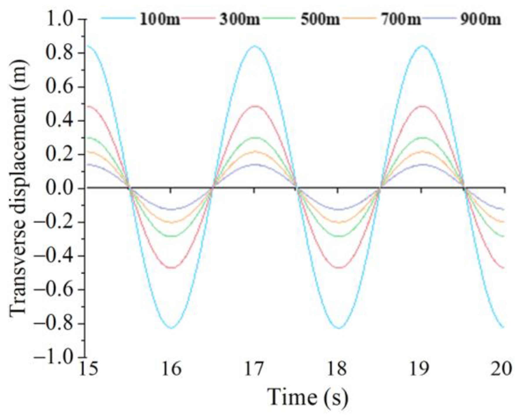
| Pipe Section Location | Numerical Simulation Method (m) | DQM Method (m) |
|---|---|---|
| 0.1 | 0.8536 | 0.8934 |
| 0.3 | 0.4952 | 0.4879 |
| 0.5 | 0.3016 | 0.2991 |
| 0.7 | 0.1954 | 0.2047 |
| 0.9 | 0.1187 | 0.1152 |
| Periodicity (Year) | 1 | 10 | 100 | |
|---|---|---|---|---|
| Wave | Significant wave height (m) | 4.8 | 5.8 | 6.5 |
| Max wave height (m) | 8.3 | 10.0 | 11.3 | |
| Period (s) | 7.8 | 9.0 | 9.8 | |
| Horizontal | Factors | |||
|---|---|---|---|---|
| Wave (m) | Current (m/s) | Internal Flow Velocity (m/s) | The Clump Weight (t) | |
| 1 | 4.8 | 0.99 | 2 | 900 |
| 2 | 5.8 | 1.09 | 4 | 1000 |
| 3 | 6.5 | 1.42 | 6 | 1100 |
| Number | Wave (m) | Current (m/s) | Internal Flow Velocity (m/s) | The Clump Weight (t) |
|---|---|---|---|---|
| 1 | 4.8 | 0.99 | 2 | 900 |
| 2 | 4.8 | 1.09 | 4 | 1000 |
| 3 | 4.8 | 1.42 | 6 | 1100 |
| 4 | 5.8 | 0.99 | 4 | 1100 |
| 5 | 5.8 | 1.09 | 6 | 900 |
| 6 | 5.8 | 1.42 | 2 | 1000 |
| 7 | 6.5 | 0.99 | 6 | 1000 |
| 8 | 6.5 | 1.09 | 2 | 1100 |
| 9 | 6.5 | 1.42 | 4 | 900 |
| Numbers | Max Lateral Displacement (m) | Max Bending Moment (kN.m) |
|---|---|---|
| 1 | 41.46 | 1854.8 |
| 2 | 46.8 | 1806.88 |
| 3 | 72.33 | 1910.79 |
| 4 | 34.73 | 1668.64 |
| 5 | 51.57 | 1892.18 |
| 6 | 78.35 | 1950.59 |
| 7 | 37.96 | 1446.81 |
| 8 | 42.88 | 1417.94 |
| 9 | 86.16 | 1840.65 |
Disclaimer/Publisher’s Note: The statements, opinions and data contained in all publications are solely those of the individual author(s) and contributor(s) and not of MDPI and/or the editor(s). MDPI and/or the editor(s) disclaim responsibility for any injury to people or property resulting from any ideas, methods, instructions or products referred to in the content. |
© 2023 by the authors. Licensee MDPI, Basel, Switzerland. This article is an open access article distributed under the terms and conditions of the Creative Commons Attribution (CC BY) license (https://creativecommons.org/licenses/by/4.0/).
Share and Cite
Zhang, Y.; Zheng, M.; Zhang, L.; Zhang, C.; Tan, J.; Zhang, Y.; Duan, M. Investigation of Dynamic Behavior of Ultra-Large Cold-Water Pipes for Ocean Thermal Energy Conversion. Dynamics 2023, 3, 468-487. https://doi.org/10.3390/dynamics3030025
Zhang Y, Zheng M, Zhang L, Zhang C, Tan J, Zhang Y, Duan M. Investigation of Dynamic Behavior of Ultra-Large Cold-Water Pipes for Ocean Thermal Energy Conversion. Dynamics. 2023; 3(3):468-487. https://doi.org/10.3390/dynamics3030025
Chicago/Turabian StyleZhang, Yanfang, Miaozi Zheng, Li Zhang, Chaofei Zhang, Jian Tan, Yulong Zhang, and Menglan Duan. 2023. "Investigation of Dynamic Behavior of Ultra-Large Cold-Water Pipes for Ocean Thermal Energy Conversion" Dynamics 3, no. 3: 468-487. https://doi.org/10.3390/dynamics3030025