Entry

Reactive Transport Processes in Proton Exchange Membrane Fuel Cells
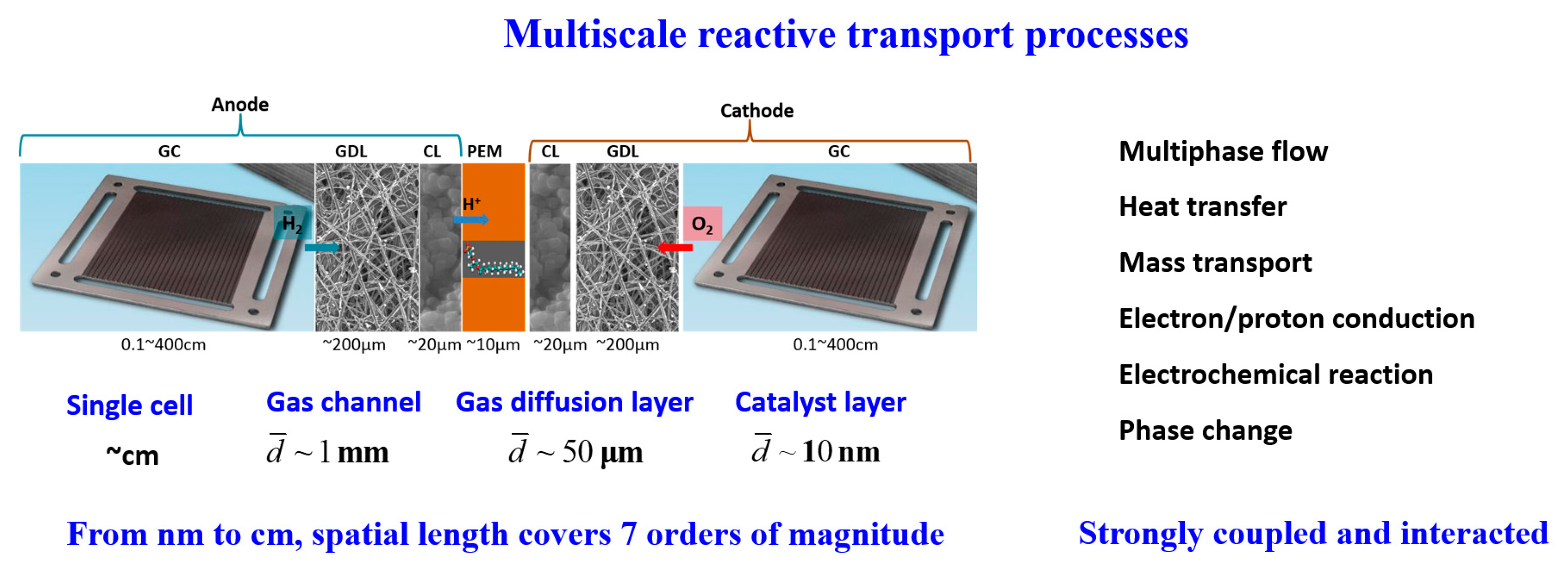
1
School of Chemical Engineering and Technology, Xi’an Jiaotong University, Xi’an 710049, China
2
Key Laboratory of Thermo-Fluid Science and Engineering of MOE, School of Energy and Power Engineering, Xi’an Jiaotong University, Xi’an 710049, China
*
Author to whom correspondence should be addressed.
Encyclopedia 2023, 3(2), 746-758; https://doi.org/10.3390/encyclopedia3020054
Submission received: 1 April 2023 / Revised: 4 June 2023 / Accepted: 14 June 2023 / Published: 19 June 2023
(This article belongs to the Collection Encyclopedia of Electrochemical Energy Storage and Conversion)

Definition

:
Proton exchange membrane fuel cells are devices that directly convert chemical energy to electricity. A hydrogen oxidation reaction takes place on the anode side, generating protons and electrons. In the cathode, oxygen reduction reaction involving oxygen, proton and electron occurs, producing water and heat. The water content in PEMFCs should be maintained at a reasonable amount to avoid water flooding or membrane dehydration. The thermal management and water management of PEMFCs are important for an efficient and stable operation of PEMFCs. Inside the multiscale spaces of PEMFCs, multiphase flow with a phase change, heat and mass transfer, proton and electron conduction, and electrochemical reaction simultaneously take place, which play important roles in the performance, lifetime and cost of PEMFCs. These processes should be well understood for better designing PEMFCs and improving the thermal management and water management.

1. Introduction

Proton exchange membrane fuel cells (PEMFCs) are devices that directly convert chemical energy to electricity. As promising next-generation power devices, PEMFCs have drawn great attention and have been extensively studied due to their many distinct advantages, such as high-power density, high efficiency, low-temperature operating and no-pollution. There are generally seven key components in a PEMFC, including catalyst layers, gas diffusion layers and gas channels on both the anode and cathode sides, as well as the proton exchange membrane sandwiched between them. In the anode catalyst layer, the following hydrogen oxidation reaction (HOR) takes place:
H 2 HOR 2 H + + 2 e
while in the cathode catalyst layer, the following oxygen reduction reaction (ORR) occurs:
O 2 + 4 H + + 4 e OOR 2 H 2 O
Complicated reactive transport processes simultaneously take place inside the multiscale structures of PEMFCs. In the anode, hydrogen flows into the gas channel, diffuses inside the gas diffusion layer, and finally arrives at the catalyst layer for the HOR in Equation (1), which generates electrons and protons. The protons generated can conduct through the PEM to the cathode side, while the transport of the electrons in the PEM is not allowed and the electrons are transported through an external circuit to the cathode side. On the cathode side, the oxygen is fed into the gas channel, which then diffuses into the gas diffusion layer and further into the catalyst layer for the ORR described in Equation (2), leading to the generation of water.
The effects of water on cell performance are complicated. On the one hand, water has to be removed from PEMFCs, because too much liquid water will block the pores in PEMFCs and cover the reactive sides, which then hinders the transport of reactants and decreases the electrical reaction surface area. Such a phenomenon is called water flooding. On the other hand, however, the PEM needs to be well hydrated to guarantee good conductivity of protons, as a PEM with a low water content leads to high proton transport resistance. Therefore, water content inside PEMFCs should be delicately managed.
During the operation of PEMFCs, usually about 50% of the chemical energy is converted to electricity, while the other 50% is turned to heat. In other words, for a 1 kW PEMFC with 50% efficiency, 1 kW of heat is generated. Heat generated in PEMFCs includes the irreversibility of electrochemical reactions and ohmic resistance, as well as water vapor condensation. As mentioned before, in PEMFCs, the membrane should be well hydrated for preventing high ohmic loss and there should not be too much liquid water to avoid water flooding, thus PEMFCs are correspondingly operated at a temperature range of 60–80 °C. Therefore, the heat generated should be efficiently dissipated out of the PEMFC, and the balance of heat generation and heat removal maintains the desirable temperature-operating range of PEMFCs. In fact, the thermal management and water management of PEMFCs are coupled with each other, and together they determine the stable and efficient operation of PEMFCs. The thermal management and water management are very complicated due to the complex multiscale structures, the variation in surface properties of different components, as well as the temperature gradient inside PEMFCs. It should be noted that while the focus of the present encyclopedia is about low-temperature PEMFCs, high-temperature PEMFCs using PBI-based membranes and operating at much higher temperatures, where many of the transport processes related to liquid water, are no longer relevant. The structures of PEMFCs are in fact multiscale. The typical pore size in the catalyst layer is on a nanometer scale, while that in the gas diffusion layer is ~10 μm. The hydraulic diameter of the gas channels is about 1 mm, while the length of the gas channel or the size of a single PEMFC in the in-plane direction is at the magnitude of centimeters. It can be concluded that the reactive transport space inside PEMFCs covers about seven orders of magnitude, presenting typical multiscale characteristics.
From the above description, it can be found that complex reactive transport processes take place inside the multiscale structures of PEMFCs, including air–water two-phase flow with a phase change, heat transfer, mass transport, proton and electron conduction, and electrochemical reaction, as shown in Figure 1. These multiphase reactive transport processes are inherently coupled and strongly interact with each other, and together, they determine the overall cell performance. In fact, the performance of PEMFCs is limited by three major losses, namely the activation loss due to the sluggish reaction kinetics of the ORR, ohmic loss due to the transport resistance of protons and electrons, and mass transport loss due to the transport resistance of the reactants (hydrogen and oxygen). Understanding the reactive transport characteristics, as well as the coupling mechanisms of the above-mentioned reactive transport processes is crucial for improving the performance of PEMFCs through reduced losses and enhanced water management and thermal management. In Section 2, different processes within different components of the PEMFC will be introduced, and the key mechanisms will be discussed.

2. State of the Art

2.1. Proton Exchange Membrane

The preferred choice of PEMs for PEMFCs are perfluorosulfonic acid (PFSA) membranes such as Nafion® [1]. These membranes offer the combination of excellent mechanical strength, chemical stability, and high permselectivity for non-ionized molecules, thus limiting reactant crossover. The PFSA membranes are highly prized for their ionic conductivity, which is significantly influenced by hydration; therefore, the transport of ions and water is of primary importance.
There is a general consensus that a hydrated PFSA membrane is a two-phase system, consisting of a nanoporous perfluorinated matrix phase and a water–ion phase distributed within it. It was found that as the degree of hydration within the membrane increased, the proton conductivity also increased, indicating a close relationship between proton transport and water content within the membranes. The “vehicle mechanism” and “Grotthuss mechanism” [2,3] reveal that protons combine with carriers such as H2O to form H3O+, H5O2+, or H9O4+, and are transported within sulfonic acid groups to facilitate proton conduction.
Water in the membranes is generally considered dissolved water (or membrane water), bound to sulfonic acid groups. The amount of water in the membrane is defined as the number of water molecules carried per sulfonic acid group, i.e., λ = nw/nsulf [4]. The transport of water in the membrane involves two mechanisms: the electro-osmotic drag and back-diffusion. The electro-osmotic drag involves the transport of protons generated at the anode to the cathode, dragging along with water molecules and causing the movement of water at the anode to the cathode [5]. Back-diffusion is the diffusion of water from the cathode to the anode under the concentration gradient, as water is generated by the ORR on the cathode side [5]. In a stable operating fuel cell, the electro-osmotic drag and back-diffusion should be balanced, and the amount of dissolved water in the membrane should remain stable. When the amount of dissolved water exceeds the saturation level, the excess water desorbs from the membrane, turning into liquid or gaseous water. Excessive liquid water can block the pores, cause flooding, and hinder the transport of reaction gases. Therefore, the amount of dissolved water in the membrane should be maintained at a desirable level to enhance proton conductivity and avoid flooding, which poses a challenge for water management in PEMFCs.
Although membranes can prevent the transport of reaction gases across the membrane, a small amount of gas can still permeate into the membrane. Under high-potential conditions, the Pt catalyst at the cathode can dissolve over time, generating Pt2+ ions. These ions diffuse into the membrane and undergo reduction reactions with the hydrogen gas that permeates from the anode, re-precipitating within the membrane and forming a Pt band [6]. This behavior belongs to the degradation process of PEMFCs and will be discussed in detail in the Section 2.7.

2.2. Catalyst Layer

In PEMFCs, the catalyst layer (CL) plays a critical role in facilitating electrochemical reactions. The CL is typically a porous layer composed of carbon-supported Pt nanoparticles, ionomer, and pores, as shown in Figure 1, which is coated onto a membrane electrode assembly (MEA). Triple-phase boundaries are formed in the CL by conducting phases for the ion, electron, and reactants where electrochemical reactions occur [7]. Because of its composite structures and all transport processes within it, the CL is the most complicated component in PEMFCs. The transport of charged species, radicals, and uncharged species such as oxygen, hydrogen, nitrogen, and water, occurs in distinct pathways provided by the electrolyte, carbon, and gas pores within the confined space of the 5–10 μm layer.
Charged species, including protons and electrons, are conducted in the ionomer and carbon support, respectively, while uncharged species are transported in the multi-component system, and complex cross-interface transport processes occur. Considering the oxygen transport process in the cathode CL as an example, oxygen first diffuses from the gas diffusion layer (GDL) or microporous layer (MPL) into the pores of the CL. Oxygen then arrives at the ionomer surface and dissolves at the pore–ionomer interface, causing a decrease in oxygen concentration. Subsequently, the oxygen diffused in the ionomer film arrives at the surface of the Pt particles and undergoes an adsorption process at the ionomer–Pt interface, which further reduces the oxygen concentration. Finally, an electrochemical reaction occurs on the surface of the Pt particles. In addition, the water transport process in the cathode CL is also very complex. The generated water diffuses in the ionomer in the dissolved state, arrives at the pore–ionomer interface, generates liquid or gaseous water and desorbs from the ionomer, and migrates out of the CLs through the pores between the carbon particles.
Due to the extremely small scale of CLs (pores, ionomer, Pt particles, and carbon particles are all in the nanoscale range), it is still challenging to observe the reactive transport processes in the CLs in situ using experimental techniques. Experimental methods are mostly used for the ex situ characterization of CL structures or macroscopic performance parameters (electrochemical-specific surface area, electrochemical impedance spectroscopy, oxygen transport resistance, etc.) [8,9].
Numerical methods are effective tools for studying reactive transport processes within CLs. It is crucial to use numerical methods to develop CL models in order to reveal the mechanisms of reactive transport processes within CLs. The CL models commonly used in literature can be classified into three kinds, including homogeneous models, agglomerate models, and pore-scale models.
(1)
Homogeneous model
Homogeneous models account for the significant macroscopic phenomena and composition of CLs by correlating the properties of porous CLs with the volume fraction of each constituent material, including Pt, carbon, and ionomer [10]. These models incorporate electronic and ionic transport, as well as the diffusion of reactants and products through void spaces. To describe the transport capacity for specific processes such as fluid flow, heat conduction, and mass transport, macroscopic transport properties are utilized, including permeability, effective thermal conductivity, and effective diffusivity.
(2)
Agglomerate model
The agglomerate model accounts for the typically agglomerated structures of platinum particles supported by carbon. Specifically, the CL comprises agglomerates of carbon-supported Pt particles which are covered by an ionomer film, and the transport phenomena are described as bulk transport between agglomerates and local reactive transport within agglomerates. These agglomerates can take the form of either cylindrical or spherical shapes, consisting of carbon and Pt particles covered by ionomers [11]. In the case of spherical agglomerates, oxygen diffusion occurs through inter-agglomerate pores, dissolves into the ionomer phase, and ultimately enters the agglomerate core (a mixture of carbon, Pt, and ionomer in the conventional agglomerate model) for the ORR.
The current density generated by the ORR in an agglomerate is as follows [12]:
i = n F C 0 1 r agg + δ δ a agg r agg D N + 1 k elec E r
where C0 is the oxygen concentration on the outer surface of the electrolyte covered on the agglomerate core, δ is the electrolyte thickness, aagg is the specific surface area of the agglomerate, DN is the oxygen diffusivity within the electrolyte, and kelec is the reaction rate constant. Er is the dimensionless effectiveness factor, and for the spherical agglomerate, the expression is as follows:
E r = 3 T h 2 T h coth T h 1 T h = r agg k elec D eff
with the Thiele modulus, Th, being defined as the ratio of the surface reaction rate on the agglomerate surface to the diffusion rate inside the agglomerate core [12].
Furthermore, the above-mentioned agglomerate models have been developed to incorporate factors such as liquid water, and species adsorption and desorption on the catalyst surface [13].
The question of whether the ionomer fills the agglomerate structures of the CL remains a matter of debate. While some observations from molecular dynamic simulations and nanoscale experiments suggest that the agglomerates, particularly the micropores within the carbon particles, are free of ionomer, this is yet to be definitively established. Recent studies suggest that the agglomerate model fails to accurately describe mass transport in the concentration polarization region and cannot account for Pt dispersion effects. As a result, it yields unphysical results, such as an identical limiting current density under different Pt loadings. To reconcile simulation results with experimental data, the assumed ionomer thickness in the agglomerate model is typically much higher than the typical values observed in experiments. Experimental results indicate that as the Pt loading decreases, the extra transport resistance increases, resulting in a decrease in the limiting current density. Under lower Pt loadings, oxygen must travel a longer distance to reach the Pt surface for an electrochemical reaction, resulting in increased transport resistance. Consequently, agglomerate models that take into account local transport processes around reactive sites, such as the single-carbon particle-based model, have been proposed to predict extra transport resistance under lower Pt loadings more accurately [14].
(3)
Pore-scale model
Thus far, the macroscopic models of CLs were derived using the volume-averaging method, relying on statistical parameters (such as porosity, specific surface area, and tortuosity, etc.) and macroscopic transport properties (permeability, effective diffusivity, effective thermal conductivity, etc.) to describe reactive transport processes. However, advanced experimental techniques have made it possible to reveal the microscopic details of CL structures, enabling direct numerical simulation (DNS) or pore-scale modeling [15]. Pore-scale models resolve the porous structures directly, eliminating the need for statistical parameters and macroscopic transport properties. The general steps for pore-scale modeling are: (1) accurately describing the porous structures and distributions of all constituents; (2) establishing the physicochemical models for reactive transport processes and numerically solving governing equations over the reconstructed structures; and (3) investigating the effects of porous structures and interfacial characteristics on transport processes.
Pore-scale modeling provides details of the underlying physical, chemical, and electrical processes, providing insights into the intrinsic characteristics that govern macroscopic parameters. It also reveals the effects of microscopic structures and interfacial properties on reactive transport processes, which are significant when examining heterogeneity. By adopting appropriate upscaling schemes, the macroscopic effective transport properties required in continuum-scale models can be obtained based on pore-scale simulation results. Ultimately, porous medium performance can be improved by modifying porous structures and surface properties based on an understanding of the interplay between realistic structures and pore-scale reactive transport processes.
The lattice Boltzmann method, widely adopted for its powerful ability to handle complicated geometries, has been used to simulate pore-scale reactive transport processes inside CLs. For example, it has been used to investigate the effects of volume fraction and distributions of different constituents on the transport of oxygen, water vapor proton and electron conduction. Recently, pore-scale modeling has played an essential role in understanding the local transport resistance under low Pt loading [16]. Local transport resistance, which causes the reduction in the limiting current density, is related to the local structures around reactive sites. Pore-scale modeling has been employed to investigate the mechanisms of local transport resistance by solving oxygen transport processes in porous structures with nanoscale distributions of all the transport pathways resolved.

2.3. Gas Diffusion Layer

The GDL plays multiple roles in PEMFCs, including providing pathways for reactant gas, produced water, heat, and electron transport, as well as offering mechanical support for other porous components in PEMFCs, including CLs, and sometimes MPLs. Carbon cloth and carbon paper are two porous materials usually employed for GDL [17]. Figure 1 shows an SEM image of carbon paper GDL, which consists of randomly packed carbon fibers with a diameter of 6–10 μm. The thickness of GDL is about 100–300 μm, the typical porosity is about 0.6–0.9, and the typical pore size is 10–100 μm. Considering the cathode GDL as an example, the transport processes inside GDL can be described as follows. Oxygen from the gas channel transports through the GDL to the CLs, while the water produced in the CLs migrates through the GDL to the gas channels. The heat generated in the CLs also transfers through the GDL, and the electrons also conduct in the solid skeleton of the GDL, namely the carbon fibers. Several macroscopic transport properties are employed to describe the transport capacity of the GDL. Depending on the different types of GDL used, the values of the macroscopic transport properties may be different. Generally, the permeability of the GDL, describing the capacity of the GDL for fluid flow, is about 10−12–10−11 m2. The effective diffusivity of the GDL, standing for the capacity of the GDL for gas diffusion, is usually expressed as D0εα (called the Bruggeman equation), with α from 1.5 to 4 [18], and the effective thermal conductivity of the GDL is about 0.2 W/mK–2 W/mK.
The most complicated transport process inside PEMFCs is the air–water two-phase flow. The GDL is usually treated with hydrophobic agents such as the polytetrafluoroethylene (PTFE), leading to both hydrophilic and hydrophobic pores inside GDLs. The water generated in the CLs moves into the GDL and then flows to the gas channels. Therefore, the GDL plays an important role in the water management of PEMFCs for preventing water flooding. Several water transport mechanisms inside GDLs have been proposed, such as capillary fingering and heat pipe flow [19,20].
Various experimental techniques have been employed to investigate the in situ or ex situ two-phase flow inside GDLs, including direct optical visualization, x-ray computed tomography, neutron radiography, etc. [21,22,23]. For modeling at the continuum scale, extended Darcy equations have been widely adopted to model the air–water two-phase flow in GDLs [24,25]. In this equation, the velocity of a certain phase is proportional to the pressure gradient based on the following formula:
u g = k r , g μ g p g ,   u l = k r , l μ l p l
where kr is the relative permeability. Defining capillary pressure as pc = plpg, and noting that it is a function of saturation, the mass flux of liquid water can be expressed as follows:
m ˙ l = ρ l k r , l μ l ( p g + p c ) = ρ l μ g μ l k r , l k r , g u g ρ l k r , l μ l d p c d s s
To solve Equation (6), the relative permeability of the gas and liquid, kr,g and kr,l, as well as the relationship between the capillary pressure and saturation, should be defined. The following correlations are commonly employed:
P c = P l P g = σ cos θ ε k 0 0.5 J s
J s = 1.42 1 s 2.12 1 s 2 + 1.26 1 s 3 , θ < 90 ° 1.42 s 2.12 s 2 + 1.26 s 3 , θ > 90 °
k r , g = ( 1 s ) n k 0 ,   k r , l = s n k 0
where σ, θ, and k0 represent surface tension, contact angle, and the intrinsic permeability, respectively. In the literature, many studies have been conducted to determine the relationship between capillary pressure and liquid water saturation. The effects of microscopic heterogeneous structures, PTFE distributions, mixed wettability, and GDL compression on the air–water two-phase flow in GDLs have also been studied in the literature for improving water management.
Pore-scale modeling has been developed as a powerful tool for revealing liquid water dynamic behaviors, as well as two-phase distributions inside the GDLs. Among the different numerical methods, the lattice Boltzmann method, due to its kinetic nature which leads to a convenient treatment of complex boundaries, has been widely adopted for such pore-scale modeling [15]. The effects of different factors, such as porous structures, distributions of PTTE, and compression of the two-phase flows have been studied in the literature [22,26]. Based on the pore-scale results, macroscopic transport properties can be predicted and the capillary pressure–saturation relationship can also be obtained. Further, taking into account the porous structures of GDL, the MPL, and even the CL, pore-scale modeling can further be employed to directly investigate the effects of liquid water dynamic behaviors on the mass transport and chemical reaction, which are helpful to evaluate both the local distribution of liquid water and the total saturation of the current density of the PEMFC [27].

2.4. Microporous Layer

To avoid water flooding inside PEMFCs, a state-of-the-art GDL is usually coated with a microporous layer (MPL) [20]. Sometimes, the GDL and MPL together are called the gas diffusion medium (GDM). The typical thickness of the MPL is about 50 μm, and the typical pore size is ~50 nm, which is sandwiched between the typical pore size of GDLs and CLs. The transport processes inside the MPL can be described by the same equations employed for the GDL. However, the roles of the MPL in PEMFCs are much more complicated. First, as the difference of the pore size between GDLs and CLs is large, adding an MPL between them can reduce the contact resistance. Second, under relatively dry conditions, the addition of an MPL increases the resistance for liquid water from the CL to the GDL, and can thus hold the water inside the CLs to keep the ionomer hydrated. Third, under a relatively high current density with excessive water generated, the MPL can reduce the number of breakthrough points of water from the CLs to the GDLs [28], thus reducing the water saturation inside the GDLs and alleviating the water flooding in GDLs. Finally, with the addition of an MPL, the thermal resistance is increased, leading to a higher temperature in CLs, which can promote the transition of the water removal mechanism from capillary-driven liquid water flow to water vapor diffusion [29]. From the above description, it can be concluded that the MPL should be dedicatedly designed, as the multiple roles are actually sometimes contradictory. For example, a too-thick MPL can reduce the number of breakthrough points of water from the CLs to the GDLs, which is required when there is excessive water in PEMFCs, but can also increase the transport resistance of oxygen from GDLs to CLs when liquid water is in deficit. The effects of the materials, structures (pore size, porosity, thickness, etc.), and wettability have been extensively studied in the literature to understand the roles of MPL in water and reactant gas transport; nevertheless, there are still debates about the roles and mechanisms of transport processes inside the MPLs.

2.5. Gas Channels

The bipolar plate, together with the gas channels embedded in it, contributes to about 60–80% weight, 70–90% volume, and 30–40% cost of the entire PEMFC [30]. The bipolar plates play multiple roles in PEMFCs, including distributing the reactant gas, discharging the excessive liquid water, dissipating the waste heat, and conducting the electrons. The design of the gas channels significantly affects the reactant distributions and water removal. In a gas channel, three walls are in the bipolar plates, while the last wall is actually the porous GDL [31]. There have been extensive studies of the gas channel design, with parallel, interdigitated, serpentine, pin, and spiral gas channels as typical examples. Alongside that, many novel channels have also been proposed to enhance mass transport, such as the bio-inspired gas channels [32] and 3D fine mesh gas channels of Toyota [33].
In fact, the geometry and wettability of the gas channels determine the water transport in the gas channels and the water management in the entire PEMFC. Liquid water transport in the gas channels can be described as the random growth of liquid water from the GDL to the GC, and the complex liquid water dynamic behaviors in the gas channels with various in-plane patterns, cross sections, size, and wettability under the effects of air flow. The water droplet and water film are two typical flow patterns of liquid water in the gas channels. Direct visualization experiments have been conducted in the literature [34,35]. Moreover, modeling water transport in the gas channel has gained extensive attention. The volume of fluid (VOF) method has been extensively employed in the literature to study two-phase flow inside gas channels [36,37]. This method has successfully captured the dynamic behaviors of water inside the gas channels, such as droplet emergence from the GDL, droplet growth, droplet detachment, droplet coalescence, water accumulation, water removal, etc. It also has been employed to explore the effects of channel size and different channel cross sections such as square, rectangular, semicircle, trapezoid, etc. While the GDL is usually hydrophobic, the effects of the wettability of other walls are also studied. It was found the hydrophilic walls of the GC can facilitate the removal of water from the GDL to the GC through capillary force, and leads to the formation of water film in the gas channels, with which the blockage of the gas channels is less serious compared with water droplets [38]. The VOF method is coupled with the mass reactive transport model to understand the coupled mechanisms between water dynamic behaviors, oxygen transport, and the ORR reaction [38,39]. Thus, the gas channel design can be thoroughly evaluated in terms of the pressure drop, coverage of GDL, and current density.

2.6. The Cooling of PEMFCs

As mentioned previously, the operating temperature range of PEMFCs is about 60–80 °C. It seems that it is easier to cool the PEMFC system when compared with a typical internal combustion engine with an operating temperature of about 1000 ℃. However, the cooling of PEMFCs is in fact more difficult, which is unintuitive. When considering a PEMFC and a typical internal combustion engine, both which are 10 kW with an efficiency of 50%, the heat generated for both the PEMFC and the internal combustion engine is also 10 kW. According to the Newton cooling law, the heat dissipated, Q[J], is proportional to hAΔT, with h [W/m2K] as the heat transfer coefficient, A as the heat transfer area, and ΔT the temperature difference between the heat source and the environment. Since the ΔT of the internal combustion engine is much higher than that of the PEMFC, it can be easily concluded that to dissipate the same heat of 10 kW, the hA of the PEMFC should be much higher, indicating that a large heat exchanger should be employed or the h should be greatly increased. In practical applications, the space in the system, for example, in a vehicle, is actually limited, thus posing a great challenge for the cooling of PEMFCs.
Currently, two cooling methods are widely adopted for PEMFCs, namely air-cooling and liquid-cooling. Usually, for a PEMFC with a relatively small power density (less than 5 kW), air-cooling can be adopted, while for a large power density PEMFC, liquid-cooling should be used with a high heat transfer coefficient. In an air-cooling PEMFC, the air is supplied into the cathode side for both providing the reactant for the ORR and cooling the PEMFC. Compared with the liquid-cooling system, the air-cooling system is much simpler, without auxiliary equipment such as a humidifier, water pump, air compressor, etc., which are helpful for reducing the size, weight, and cost of PEMFCs. Since the heat conductivity and heat capacity of air are much lower than that of liquid water, air with an extremely high stoichiometry ratio is usually provided by the fan on the cathode side. The air with a high stoichiometry ratio and low humidity will evaporate the water generated, causing a membrane dehydration problem. Therefore, compared with the liquid-cooling PEMFCs of which the main task of water management is avoiding water flooding, in air-cooling PEMFCs, it usually is required to keep water generated at the cathode to prevent membrane dehydration. For liquid-cooling with deionized water as the coolant, the cooling channels should be designed in the bipolar plate, and liquid water with low temperature flows in the cooling channel exchanges heat with the PEMFC, and finally flows out of the cooling channel. The design of the cooling channel is a hot topic, and the effects of channel patterns, size, and shape have been extensively studied in the literature [40].
In practice, the waste heat can be recovered, for example, for preheating the reactant, providing hot water in the combined heat and power system (CPH), or driving chillers in a combined cooling and power (CCP) system [41]. A PEMFC-based CPH system can reach total efficiency as high as 80–90%.

2.7. Degradation

The stable operation of PEMFCs is crucial for ensuring operational safety. However, during extreme operating conditions such as water flooding, start-up/shut-down processes, and hydrogen purge, PEMFCs undergo degradation, leading to a reduction in performance over time. Degradation processes in the key components of PEMFCs are introduced as follows.
(1)
Membrane degradation
The membrane could degrade over time due to various factors: (i) Chemical degradation [42]: Exposure to harsh chemicals, such as impurities in the hydrogen or air streams, can cause the membrane to degrade. This can result in the formation of cracks, holes, or other defects that can compromise the cell performance. (ii) Electrochemical degradation [1]: Electrochemical reactions can occur on the surface of the membrane during operation, generating reactive species such as free radicals that attack and damage the membrane. (iii) Mechanical degradation [43]: Mechanical stresses, such as changes in temperature, humidity or pressure, can cause the membrane to deform or crack. This will lead to leaks or other issues that can affect the performance of the PEMFC.
(2)
Catalyst layer degradation
The degradation processes of the CL include: (i) Pt degradation [44,45], which is caused by corrosion, agglomeration, Ostwald ripening, and the detachment of the Pt or Pt alloys typically used in PEMFC catalysts. These degradation processes can lead to a reduction in catalytic activity, an increase in particle size, and consequently, a decrease in the overall performance of the PEMFC. Additionally, Pt in the cathode CL may dissolve and generate Pt2+ ions due to the higher potential at the cathode. These ions may diffuse into the proton exchange membrane, undergo reduction reactions, and precipitate with hydrogen permeated by the anode, resulting in the formation of a Pt band in the membrane. This phenomenon leads to a loss of Pt loading in the cathode CL and a decrease in the number of reaction sites. (ii) Carbon corrosion [46]: The carbon support material in the CL may undergo corrosion due to the harsh operating conditions of the PEMFC, including high overpotential, high temperature, high relative humidity, and a low pH. This corrosion can result in a reduction in the structural support of the CL, causing the CL structure to collapse and increasing the oxygen transport resistance. (iii) Ionomer degradation [1]: The ionomer in CLs can degrade over time due to exposure to high temperature, low humidity, and chemical contaminants. This degradation can cause a decrease in proton conductivity, which can in turn lead to a reduced performance of the PEMFC. (iv) Local gas starvation [47]: In certain instances, excess water can accumulate in the CL pores, leading to flooding and local gas starvation. Local gas starvation within the CL can result in an increase in the electrical potential, which can cause the degradation of both Pt and carbon. Therefore, effective water management can not only enhance cell performance, but also delay the aging of PEMFCs.
(3)
Gas diffusion layer degradation
The GDL can degrade due to various factors, including: (i) Carbon corrosion, which follows similar kinetics in the CL and is caused by carbon oxidation due to a high local potential. Carbon corrosion in the GDL can cause the GDL structure to collapse, resulting in the loss of porosity and increased contact resistance between the GDL and the CL. This can lead to an increase in internal resistance and a decrease in power output. (ii) PTFE degradation [48]: PTFE may degrade or detach from the surface of the carbon fiber due to flow erosion or corrosion at the connection between the PTFE and carbon fiber, leading to a loss of hydrophobicity. This can result in flooding of the GDL and the formation of a water layer between the GDL and the CL, thus reducing the cell performance.
(4)
Mechanical degradation
The PEMFC can also experience mechanical degradation due to vibrations, thermal/humidity cycling, and other stresses, leading to the cracking or delamination of the layers and decreased performance. Therefore, it is crucial to maintain the stability of the PEMFC stack during operation, to avoid any mechanical degradation and ensure stable force.

3. Trends and Developments

Over the past two decades, due to the remarkable development of both experimental and numerical methods, multiscale, multiphase reactive transport processes inside PEMFCs have been extensively studied, and the underlying mechanisms of different processes in the key components of PEMFCs have been revealed, including the two-phase flow, multicomponent transport, heat transfer, and an electrochemical reaction. In fact, based on the above understanding, many multiphase, multicomponent, and non-isothermal models have been proposed to describe the reactive transport processes inside PEMFCs. It is worth mentioning that the reactive transport processes inside the porous components of PEMFCs are extremely complicated and due to the microscopic and nanoscopic scales related, new phenomena have been continuously discovered; however, the mechanisms of some phenomena are still not clear and need further investigation. Particularly, the following transport processes should be further studied for achieving an efficient and stable operation of PEMFCs:
(1)
In the GDL, phase change multiphase flows takes place in the isotropic porous structures. Currently, most studies focus on isothermal air–water two-phase flow, neglecting the effects of heat transfer. Since the heat pipe flow has been recognized as an important mechanism for the water removal inside GDLs in which vapor flow is believed to play important roles for removing water, it is important to investigate the phase change behaviors under different temperature gradients. Thus a better GDL which can effectively remove excessive water and provide a pathway for reactants with a low resistance should be designed.
(2)
In the CL, as mentioned previously, great effort has been devoted to study the oxygen local transport resistance under a relatively low Pt loading, and several hypotheses have been proposed to explain the extra transport resistance. Since it is important to reduce the Pt loading and maintain the higher performance for PEMFC commercialization, it is urgent to reveal the underlying mechanisms of the local transport resistance and understand the effects of the nanoscale distributions of the ionomer, carbon particles, and Pt distributions on the local transport.
(3)
Different processes take place inside the multiscale PEMFCs and each process is related to its unique characteristic time. Particularly, due to the low thermal conductivity of the key components inside PEMFCs, the transient heat transfer process is not well understood, such as the start-up, shut-down, freeze–thaw cycling, which need to be accurately modeled for developing appropriate control algorithms.
(4)
The assembly pressure will cause the compression of different components inside PEMFCs, especially the porous electrodes. The interaction between the structure evolution due to compression and the multiphase reactive transport processes inside PEMFCs should be further explored for a better design of PEMFCs.
(5)
Degradation results from the complicated multiphase reactive transport processes inside PEMFCs under various operating conditions. The degradation changes the structures, surface wettability, and inner physicochemical properties of key components inside PEMFCs, and in turn affects the multiphase reactive transport processes. Next-generation PEMFCs will operate at higher potentials and current densities. Under such circumstances, degradation issues are likely more severe than the current designs. It is important to understand the coupling mechanisms between degradation and multiphase reactive transport processes.

4. Conclusions and Prospects

In this encyclopedia, reactive transport processes inside different components with multiscale structures of PEMFCs are introduced. There components include the PEM, CL, GDL, and GC. Since the thermal management and water management of PEMFCs are very important, water transport mechanisms in different components are discussed in detail, and the cooling of PEMFCs is also introduced. The trends and developments of studying reactive transport processes in PEMFCs are also presented, including phase change two-phase flow in the GDL related to heat pipe effects, mechanisms of the local transport resistance, transient behaviors such as heat transfer, effects of assembly pressure, and degradation. It should be remembered that reactive transport processes in PEMFCs are actually multiscale processes. Developing advanced multiscale methods, especially microscale and nanoscale methods, is helpful for exploring reactive transport processes in PEMFCs. In the future, the PEMFC will operate under more hostile environments such as low humidity, rare air, extremely cold weather, etc. Furthermore, the power density requirement of PEMFCs is continuously increasing, from 4 kW/L currently, to 9 kW/L. It is expected that the operating and structural conditions for the reactive transport processes in PEMFCs will change in the future, and the thermal management and water management of PEMFCs will be more challenging.

Author Contributions

Conceptualization, T.M., R.Z., L.C. and Q.Z.; methodology, T.M. and R.Z.; investigation, T.M.; writing—original draft preparation, T.M. and R.Z.; writing—review and editing, L.C. and Q.Z.; supervision, Q.Z.; funding acquisition, T.M. All authors have read and agreed to the published version of the manuscript.

Funding

This research was funded by National Natural Science Foundation of China (51906187).

Institutional Review Board Statement

Not applicable.

Informed Consent Statement

Not applicable.

Data Availability Statement

Not applicable.

Conflicts of Interest

The authors declare no conflict of interest.

References

  1. Okonkwo, P.C.; Ben Belgacem, I.; Emori, W.; Uzoma, P.C. Nafion degradation mechanisms in proton exchange membrane fuel cell (PEMFC) system: A review. Int. J. Hydrogen Energy 2021, 46, 27956–27973. [Google Scholar] [CrossRef]
  2. Kreuer, K.-D.; Rabenau, A.; Weppner, W. Vehicle Mechanism, A New Model for the Interpretation of the Conductivity of Fast Proton Conductors. Angew. Chem. Int. Ed. Engl. 1982, 21, 208–209. [Google Scholar] [CrossRef]
  3. Kreuer, K.-D. Proton Conductivity: Materials and Applications. Chem. Mater. 1996, 8, 610–641. [Google Scholar] [CrossRef]
  4. Ye, Q.; Nguyen, T.V. Three-Dimensional Simulation of Liquid Water Distribution in a PEMFC with Experimentally Measured Capillary Functions. J. Electrochem. Soc. 2007, 154, B1242. [Google Scholar] [CrossRef]
  5. Springer, T.E.; Zawodzinski, T.A.; Gottesfeld, S. Polymer Electrolyte Fuel Cell Model. J. Electrochem. Soc. 1991, 138, 2334. [Google Scholar] [CrossRef]
  6. Zhang, J.; Litteer, B.A.; Gu, W.; Liu, H.; Gasteiger, H.A. Effect of Hydrogen and Oxygen Partial Pressure on Pt Precipitation within the Membrane of PEMFCs. J. Electrochem. Soc. 2007, 154, B1006. [Google Scholar] [CrossRef]
  7. Van Dao, D.; Adilbish, G.; Le, T.D.; Lee, I.-H.; Yu, Y.-T. Triple phase boundary and power density enhancement in PEMFCs of a Pt/C electrode with double catalyst layers. RSC Adv. 2019, 9, 15635–15641. [Google Scholar] [CrossRef] [Green Version]
  8. He, W.; Tang, F.; Li, X.; Zhang, C.; Ming, P. Quantification and evolution on degradation mechanisms of proton exchange membrane fuel cell catalyst layer under dynamic testing conditions. Int. J. Hydrogen Energy 2023, 48, 18032–18040. [Google Scholar] [CrossRef]
  9. Tan, X.; Shahgaldi, S.; Li, X. The effect of non-spherical platinum nanoparticle sizes on the performance and durability of proton exchange membrane fuel cells. Adv. Appl. Energy 2021, 4, 100071. [Google Scholar] [CrossRef]
  10. Gloaguen, F.; Convert, P.; Gamburzev, S.; Velev, O.A.; Srinivasan, S. An evaluation of the macro-homogeneous and agglomerate model for oxygen reduction in PEMFCs. Electrochim. Acta 1998, 43, 3767–3772. [Google Scholar] [CrossRef]
  11. Jain, P.; Biegler, L.T.; Jhon, M.S. Sensitivity of PEFC Models to Cathode Layer Microstructure. J. Electrochem. Soc. 2010, 157, B1222–B1229. [Google Scholar] [CrossRef]
  12. Moore, M.; Wardlaw, P.; Dobson, P.; Boisvert, J.J.; Putz, A.; Spiteri, R.J.; Secanell, M. Understanding the Effect of Kinetic and Mass Transport Processes in Cathode Agglomerates. J. Electrochem. Soc. 2014, 161, E3125–E3137. [Google Scholar] [CrossRef]
  13. Jiao, K.; Li, X. Water transport in polymer electrolyte membrane fuel cells. Prog. Energy Combust. Sci. 2011, 37, 221–291. [Google Scholar] [CrossRef]
  14. Hao, L.; Moriyama, K.; Gu, W.; Wang, C.-Y. Modeling and Experimental Validation of Pt Loading and Electrode Composition Effects in PEM Fuel Cells. J. Electrochem. Soc. 2015, 162, F854–F867. [Google Scholar] [CrossRef]
  15. Chen, L.; He, A.; Zhao, J.; Kang, Q.; Li, Z.-Y.; Carmeliet, J.; Shikazono, N.; Tao, W.-Q. Pore-scale modeling of complex transport phenomena in porous media. Prog. Energy Combust. Sci. 2022, 88, 100968. [Google Scholar] [CrossRef]
  16. Zhang, R.; Min, T.; Chen, L.; Li, H.; Yan, J.; Tao, W.-Q. Pore-scale study of effects of relative humidity on reactive transport processes in catalyst layers in PEMFC. Appl. Energy 2022, 323, 119553. [Google Scholar] [CrossRef]
  17. Fadzillah, D.M.; Rosli, M.I.; Talib, M.Z.M.; Kamarudin, S.K.; Daud, W.R.W. Review on microstructure modelling of a gas diffusion layer for proton exchange membrane fuel cells. Renew. Sustain. Energy Rev. 2016, 77, 1001–1009. [Google Scholar] [CrossRef]
  18. Shi, Q.; Feng, C.; Ming, P.; Tang, F.; Zhang, C. Compressive stress and its impact on the gas diffusion layer: A review. Int. J. Hydrogen Energy 2022, 47, 3994–4009. [Google Scholar] [CrossRef]
  19. Csoklich, C.; Sabharwal, M.; Schmidt, T.J.; Büchi, F.N. Does the thermal conductivity of gas diffusion layer matter in polymer electrolyte fuel cells? J. Power Sources 2022, 540, 231539. [Google Scholar] [CrossRef]
  20. Zhang, J.; Wang, B.; Jin, J.; Yang, S.; Li, G. A review of the microporous layer in proton exchange membrane fuel cells: Materials and structural designs based on water transport mechanism. Renew. Sustain. Energy Rev. 2022, 156, 111998. [Google Scholar] [CrossRef]
  21. Litster, S.; Sinton, D.; Djilali, N. Ex situ visualization of liquid water transport in PEM fuel cell gas diffusion layers. J. Power Sources 2006, 154, 95–105. [Google Scholar] [CrossRef]
  22. Satjaritanun, P.; Hirano, S.; Shum, A.D.; Zenyuk, I.V.; Weber, A.Z.; Weidner, J.W.; Shimpalee, S. Fundamental Understanding of Water Movement in Gas Diffusion Layer under Different Arrangements Using Combination of Direct Modeling and Experimental Visualization. J. Electrochem. Soc. 2018, 165, F1115–F1126. [Google Scholar] [CrossRef]
  23. García-Salaberri, P.A.; Zenyuk, I.V.; Shum, A.D.; Hwang, G.; Vera, M.; Weber, A.Z.; Gostick, J.T. Analysis of representative elementary volume and through-plane regional characteristics of carbon-fiber papers: Diffusivity, permeability and electrical/thermal conductivity. Int. J. Heat Mass Transf. 2018, 127, 687–703. [Google Scholar] [CrossRef]
  24. Natarajan, D.; Van Nguyen, T. A Two-Dimensional, Two-Phase, Multicomponent, Transient Model for the Cathode of a Proton Exchange Membrane Fuel Cell Using Conventional Gas Distributors. J. Electrochem. Soc. 2001, 148, A1324. [Google Scholar] [CrossRef]
  25. Wang, C.Y.; Cheng, P. Multiphase Flow and Heat Transfer in Porous Media. In Advances in Heat Transfer; Hartnett, J.P., Irvine, J.T.F., Cho, Y.I., Greene, G.A., Eds.; Elsevier: Amsterdam, The Netherlands, 1997; pp. 93–196. [Google Scholar]
  26. Yu, J.; Froning, D.; Reimer, U.; Lehnert, W. Polytetrafluorethylene effects on liquid water flowing through the gas diffusion layer of polymer electrolyte membrane fuel cells. J. Power Sources 2019, 438, 226975. [Google Scholar] [CrossRef]
  27. Guo, L.; Chen, L.; Zhang, R.; Peng, M.; Tao, W.-Q. Pore-scale simulation of two-phase flow and oxygen reactive transport in gas diffusion layer of proton exchange membrane fuel cells: Effects of nonuniform wettability and porosity. Energy 2022, 253, 124101. [Google Scholar] [CrossRef]
  28. Gostick, J.T.; Ioannidis, M.A.; Fowler, M.W.; Pritzker, M.D. On the role of the microporous layer in PEMFC operation. Electrochem. Commun. 2009, 11, 576–579. [Google Scholar] [CrossRef]
  29. Burheim, O.S.; Su, H.; Pasupathi, S.; Pharoah, J.G.; Pollet, B.G. Thermal conductivity and temperature profiles of the micro porous layers used for the polymer electrolyte membrane fuel cell. Int. J. Hydrogen Energy 2013, 38, 8437–8447. [Google Scholar] [CrossRef] [Green Version]
  30. Wilberforce, T.; El Hassan, Z.; Ogungbemi, E.; Ijaodola, O.; Khatib, F.; Durrant, A.; Thompson, J.; Baroutaji, A.; Olabi, A. A comprehensive study of the effect of bipolar plate (BP) geometry design on the performance of proton exchange membrane (PEM) fuel cells. Renew. Sustain. Energy Rev. 2019, 111, 236–260. [Google Scholar] [CrossRef]
  31. Chen, L.; He, Y.-L.; Tao, W.-Q. Effects of surface microstructures of gas diffusion layer on water droplet dynamic behaviors in a micro gas channel of proton exchange membrane fuel cells. Int. J. Heat Mass Transf. 2013, 60, 252–262. [Google Scholar] [CrossRef]
  32. Badduri, S.R.; Srinivasulu, G.N.; Rao, S.S. Influence of bio-inspired flow channel designs on the performance of a PEM fuel cell. Chin. J. Chem. Eng. 2020, 28, 824–831. [Google Scholar] [CrossRef]
  33. Kim, J.; Luo, G.; Wang, C.-Y. Modeling two-phase flow in three-dimensional complex flow-fields of proton exchange membrane fuel cells. J. Power Sources 2017, 365, 419–429. [Google Scholar] [CrossRef]
  34. Lu, Z.; Rath, C.; Zhang, G.; Kandlikar, S.G. Water management studies in PEM fuel cells, part IV: Effects of channel surface wettability, geometry and orientation on the two-phase flow in parallel gas channels. Int. J. Hydrogen Energy 2011, 36, 9864–9875. [Google Scholar] [CrossRef]
  35. Hussaini, I.S.; Wang, C.-Y. Visualization and quantification of cathode channel flooding in PEM fuel cells. J. Power Sources 2009, 187, 444–451. [Google Scholar] [CrossRef]
  36. Xu, S.; Liao, P.; Yang, D.; Li, Z.; Li, B.; Ming, P.; Zhou, X. Liquid water transport in gas flow channels of PEMFCs: A review on numerical simulations and visualization experiments. Int. J. Hydrogen Energy 2023, 48, 10118–10143. [Google Scholar] [CrossRef]
  37. Zhu, X.; Sui, P.; Djilali, N. Dynamic behaviour of liquid water emerging from a GDL pore into a PEMFC gas flow channel. J. Power Sources 2007, 172, 287–295. [Google Scholar] [CrossRef]
  38. Chen, L.; Cao, T.-F.; Li, Z.-H.; He, Y.-L.; Tao, W.-Q. Numerical investigation of liquid water distribution in the cathode side of proton exchange membrane fuel cell and its effects on cell performance. Int. J. Hydrogen Energy 2012, 37, 9155–9170. [Google Scholar] [CrossRef]
  39. Liu, L.; Guo, L.; Zhang, R.; Chen, L.; Tao, W.-Q. Numerically investigating two-phase reactive transport in multiple gas channels of proton exchange membrane fuel cells. Appl. Energy 2021, 302, 117625. [Google Scholar] [CrossRef]
  40. Baek, S.M.; Yu, S.H.; Nam, J.H.; Kim, C.-J. A numerical study on uniform cooling of large-scale PEMFCs with different coolant flow field designs. Appl. Therm. Eng. 2011, 31, 1427–1434. [Google Scholar] [CrossRef]
  41. Baroutaji, A.; Arjunan, A.; Ramadan, M.; Robinson, J.; Alaswad, A.; Abdelkareem, M.A.; Olabi, A.-G. Advancements and prospects of thermal management and waste heat recovery of PEMFC. Int. J. Thermofluids 2021, 9, 100064. [Google Scholar] [CrossRef]
  42. Singh, R.; Sui, P.C.; Wong, K.H.; Kjeang, E.; Knights, S.; Djilali, N. Modeling the Effect of Chemical Membrane Degradation on PEMFC Performance. J. Electrochem. Soc. 2018, 165, F3328–F3336. [Google Scholar] [CrossRef] [Green Version]
  43. Solasi, R.; Zou, Y.; Huang, X.; Reifsnider, K.; Condit, D. On mechanical behavior and in-plane modeling of constrained PEM fuel cell membranes subjected to hydration and temperature cycles. J. Power Sources 2007, 167, 366–377. [Google Scholar] [CrossRef]
  44. Prokop, M.; Drakselova, M.; Bouzek, K. Review of the experimental study and prediction of Pt-based catalyst degradation during PEM fuel cell operation. Curr. Opin. Electrochem. 2020, 20, 20–27. [Google Scholar] [CrossRef]
  45. Zhang, R.; Min, T.; Chen, L.; Kang, Q.; He, Y.-L.; Tao, W.-Q. Pore-scale and multiscale study of effects of Pt degradation on reactive transport processes in proton exchange membrane fuel cells. Appl. Energy 2019, 253, 113590. [Google Scholar] [CrossRef]
  46. Zhao, J.; Tu, Z.; Chan, S.H. Carbon corrosion mechanism and mitigation strategies in a proton exchange membrane fuel cell (PEMFC): A review. J. Power Sources 2021, 488, 229434. [Google Scholar] [CrossRef]
  47. Chen, H.; Zhao, X.; Zhang, T.; Pei, P. The reactant starvation of the proton exchange membrane fuel cells for vehicular applications: A review. Energy Convers. Manag. 2019, 182, 282–298. [Google Scholar] [CrossRef]
  48. Yu, S.; Li, X.; Liu, S.; Hao, J.; Shao, Z.; Yi, B. Study on hydrophobicity loss of the gas diffusion layer in PEMFCs by electrochemical oxidation. RSC Adv. 2014, 4, 3852–3856. [Google Scholar] [CrossRef]
Figure 1. Multiscale reactive transport processes in PEMFCs.
Encyclopedia 03 00054 g001
Disclaimer/Publisher’s Note: The statements, opinions and data contained in all publications are solely those of the individual author(s) and contributor(s) and not of MDPI and/or the editor(s). MDPI and/or the editor(s) disclaim responsibility for any injury to people or property resulting from any ideas, methods, instructions or products referred to in the content.

