1. Introduction
The aeronautical product assembly process is complex by nature, mainly because it involves a manual intensive operation and the use of a large number of assembly fixtures. Traditionally, it is performed by employing dedicated or modular fixed tooling that ensures the accurate location among the components and against any assembly forces. Nowadays, the process is completely manual or slightly supported by automatic actuators and the irruption of novel composite materials demands new approaches to avoid or at least reduce manual intervention. The fragile nature of the composite materials and the modification of the assembly workflow demand a more digital, flexible and higher level of automation within the assembly processes, aiming at a zero-defect assembly strategy by improving the assembly rate.
The increasing production plans defined by major aircraft manufacturers demand the reduction in the aircraft lead time (from design to delivery) but the low level of automation within the current assembly workflow is considered the main barrier toward a zero-defect assembly strategy at high assembly rates. This is where the integration of metrology within the assembly process plays a significant role. It makes it possible not only to drive the in-process quality assurance of assembled products but to supply reliable data to constantly adjust the assembly process towards a zero-defect assembly process [
1].
However, due to the close relative tolerances in the large work volumes, the production and quality production inspection of these components often encounters the limits of manufacturing and production metrology [
2]. The tradeoff between increasing component dimensions and constant or even decreasing tolerances as well as the necessity of making measurements in uncontrolled environments demand new concepts and innovative measurement technologies to be integrated into the manufacturing and assembly processes [
2,
3]. This is where the Large Scale Metrology (LSM) expertise comes in [
2]. Some LSM attributes are also suffered from within the aeronautical product assembly processes, such as the challenging tolerances, the non-negligible effect of gravity, the non-ideal environment affecting the measurement uncertainty or the small-batch production and the need for a first-time-right production [
2].
The use of metrology tools within the assembly process preparation stage also makes it possible to design, optimize and check in advance the suitability of certain metrology-aided assembly processes [
4], similar to what the virtual commissioning concept suggests to speed up the final commissioning of manufacturing tools and processes [
5,
6].
The integration of metrology within the aeronautical assembly process is not new. The concept of Measurement-Assisted Assembly (MAA) suggests any method of assembly in which measurements are used to guide the assembly processes [
7]. It encompasses a range of innovative measurement-assisted processes which enable rapid part-to-part assembly, increased use of flexible automation, traceable quality assurance and control, reduced structure weight and improved levels of precision across the dimensional scales [
7]. The state-of-the-art review of tooling for rigid part manufacturing and assembly [
7,
8] describes the assembly methods and their limitations based on the use of fixed and rigid toolings, and how external metrology solutions based on photogrammetry and laser technologies can be used to solve the lack of flexibility of these assembly methods. Mei et al. present a review of flexible and measurement-assisted assembly technologies in aircraft manufacturing, in which they suggest a digital metrology system as the basis for accurate digital flexible assembly [
9]. Muelaner et al. suggest that MAA provides many of the advantages of part-to-part assembly without requiring interchangeable parts [
1]. Schmitt et al. introduce an optical automated measuring solution that estimates and compensates for the real deformation of aircraft shells before joining through smart tooling [
10]. Zhehan et al. propose an analytical uncertainty evaluation method for resolving the uncertainty assessment of position and orientation in the aircraft components’ alignment [
11]. Kihlman et al. explain a reconfigurable tooling approach for airframe assembly based on the use of automatic devices fed by measuring data [
12]. Hu et al. present a flexible drilling jig system that is adjustable for wing-fuselage connection and adaptable to different part sizes and forms [
13]. In any case, although the automatic assembly and tooling flexible reconfiguration driven by MAA approaches are mentioned, non-meaningful bibliographic references have been found regarding the virtual metrology-aided assembly simulation concept (virtual commissioning of MAA) and its application within the aeronautical product assembly process of hardly accessible parts. This is a main novelty and contribution to this research, as previous studies deal with multiple instruments deployment or multi-station sequential measurement strategy simulations supported by uncertainty assessment exercises, whilst this application requires a single instrument location approach in a harsh line of sight set-up with agile measurement procedures. The same approach has not been found in the bibliography, as most of the applications deal with the assembly of external surfaces or accessible airplane structures, whereas this paper presents the assembly of the internal components of an aeronautical product. Hence, the motivation and therefore the novelties of the research are addressing this case study regarding the metrology-aided simulation and feasibility analysis of hardly accessible assembly scenarios. The research is focused on the measurement process simulation concerning the visibility of control points from a single instrument location and the accuracy assessment of moving parts inside the external skin or the main shell of the aeronautical product. The simulation approach follows the ISO 15530-4 method driven by the Monte Carlo simulation strategy and a digital twin of the measuring scenario and method. Therefore, this article presents a novel metrology-aided assembly method driven by automatic actuators. This is defined as a collaborative assembly tooling approach which aims to guide the assembly operator during the process of moving and positioning the parts in their design location instead of employing the traditional manual operation. This approach not only improves the level of automation, but it is also safer and more accurate as the large components to be assembled are always moved in a similar manner. This aspect is not ensured when the manipulation is manually executed, although the final position of every component within the assembly is established by the traditional rigid fixtures.
This article presents the introduction of metrology within the traditional assembly process of the Advanced Rear-End (ARE) fuselage component. The work presents how metrology is brought into the assembly process to improve, optimize or even take corrective measures before the assembly process ends when correction is more expensive or even impossible. Thus, a digital twin of either the assembly process or the metrology solution is developed to run an a priori Monte Carlo simulation to develop the novel assembly process of composite high load frames in a highly integrated composite skin driven by metrology [
14,
15].
The article describes the assembly process pipeline in detail to understand the cons and the pros of the suggested novel assembly process and how the external metrology framework collaborates with it to guarantee the quality request. The a priori simulation makes it possible to check different aspects, such as the feasibility of the measurement process, the robustness of the measuring procedure as well as the achievable accuracy regarding part positioning requests.
2. Description of the Traditional Assembly Process and the Proposed Novel Concept
Traditionally, the manufacturing and assembly processes of aeronautical structural parts involve stiff fixtures and auxiliary tooling, which ensures a precise part positioning within the emerging structure. The assembly tooling which is used to control the form of the assemblies is typically a heavy steel structure built on a concrete foundation, and it includes the mechanical references (tooling holes) that are considered as fiducial points to ensure that the final part geometry is fit-to-purpose. Thus, assembly tooling accounts for approximately 10% of the total manufacturing cost of an airframe [
7,
16]. The traditional assembly process starts first by locating the smaller parts (frames, ribs, beams, etc.) in the assembly tooling and then this structure is covered with the skin (several pieces). Exceptionally for this ARE product, as the skin is a single part, the traditional assembly sequence is not feasible. Thus, the skin is fixed to the main fixture and the frames (load and closing) and lateral beams are located and attached to it. Hence, the composite skin attached to the main tooling frame becomes the reference part during the assembly. In any case, this monolithic tooling is very expensive to be manufactured and it has long lead times and reduced flexibility to accommodate any product variation and design changes.
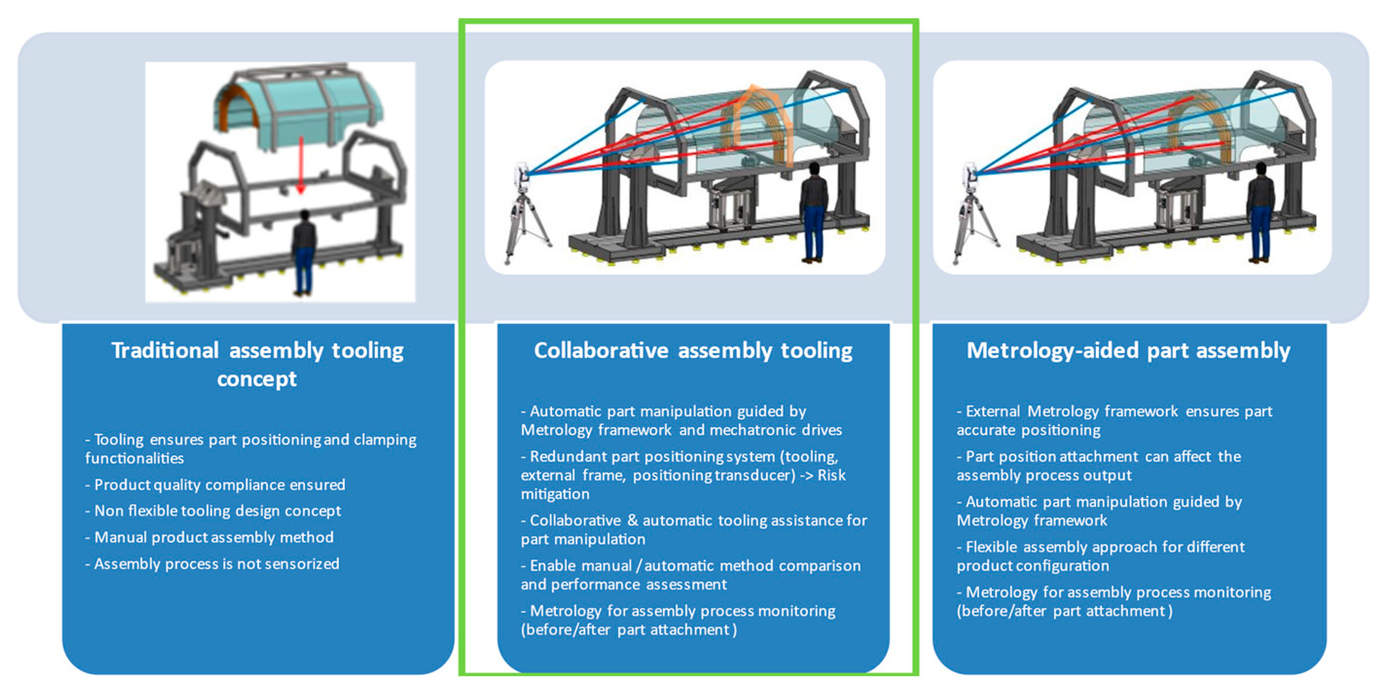
The ARE fuselage component prototype suggests a slightly different assembly process based on an external metrology framework and automatic stages. The assembly approach is driven by a metrology-aided assembly process that feeds the automatic positioning stages to locate the parts that are theoretically assumed to be fixed. The measurement instrument, in this case a laser tracker, knows by a priori rough alignment where the fiducial points (retroreflectors) attached to the fixed and moving parts of the tooling are located. Those fiducial points are automatically measured by the laser tracker and the relative position between the parts is estimated, creating a correction command for the moving stages. The correction value is automatically sent to the actuators. Thus, those measurements and the automatic displacements are iteratively performed until the theoretical location of the moving parts is reached and ensured under a certain positioning threshold (0.1 mm in XYZ). In summary, the employed design concept is close to a collaborative assembly tooling as it is based on a smart mechatronic system that aids the operator through the assembly process.
Aiming to reduce any technical risk related to the new assembly process, the real prototype shall enable both the traditional method as well as the metrology-driven method. Not only does it avoid any risky manual intervention that may damage any involved part during the assembly operation, but it also makes a comparison between the traditional and the presented approaches possible.
Figure 1 depicts the different methods assessed in this preliminary design stage. It shall be highlighted that the objective of the tooling set is to demonstrate that integrated technologies and approaches are suitable to produce precise parts.
3. Methods
This chapter describes the general elements involved in the virtual assembly process as well as the interaction among them. Initially, the components that comprise the assembly and how these components are positioned and fixed in a common mechanical structure (assembly tooling) is introduced and accompanied by technical drawings for a better understanding. After that, the assembly sequence is briefly described, focusing on how the main components are assembled. Finally, the virtual measuring strategy and the complete simulation workflow are presented.
3.1. Description of the Product
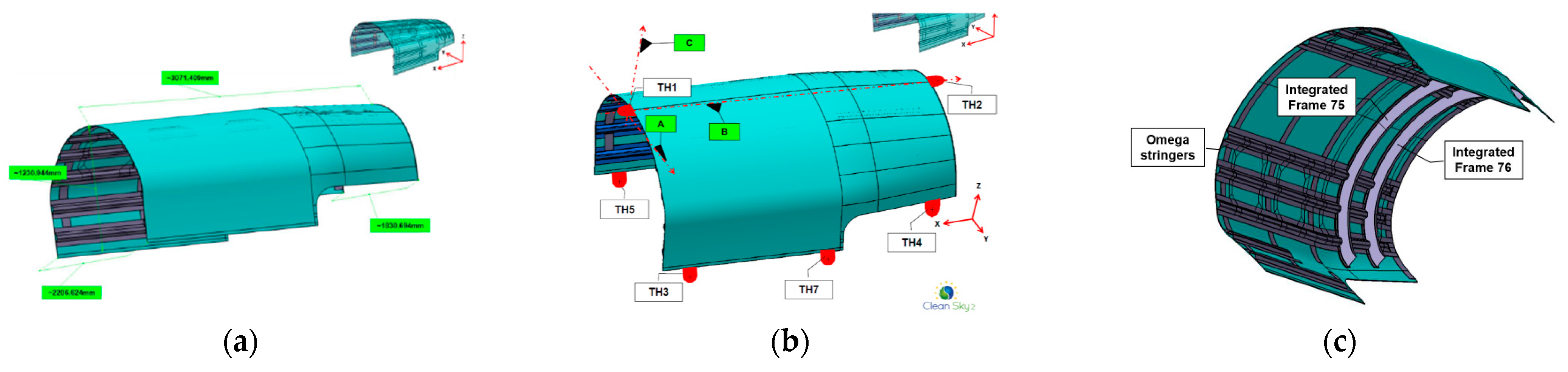
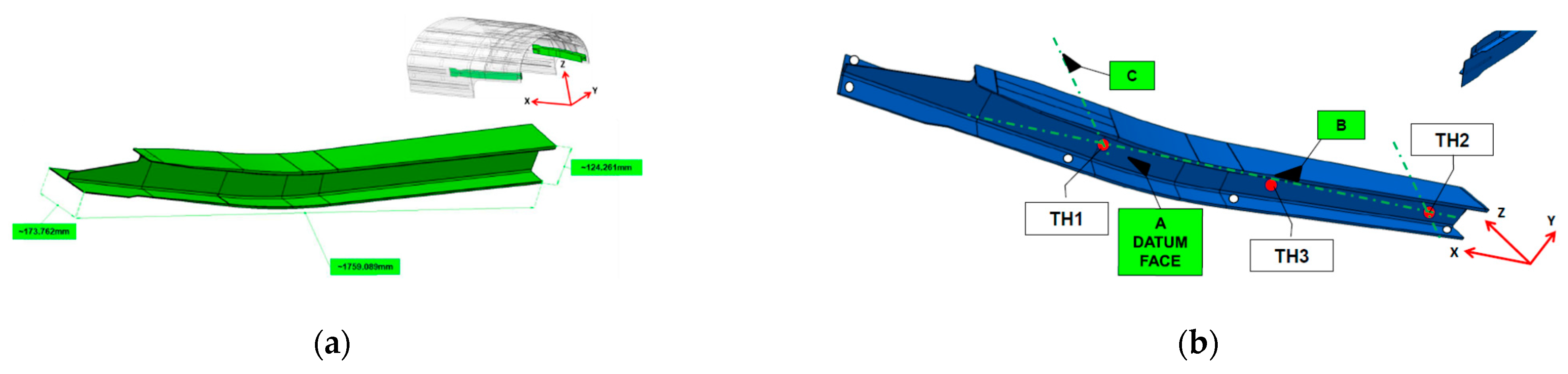
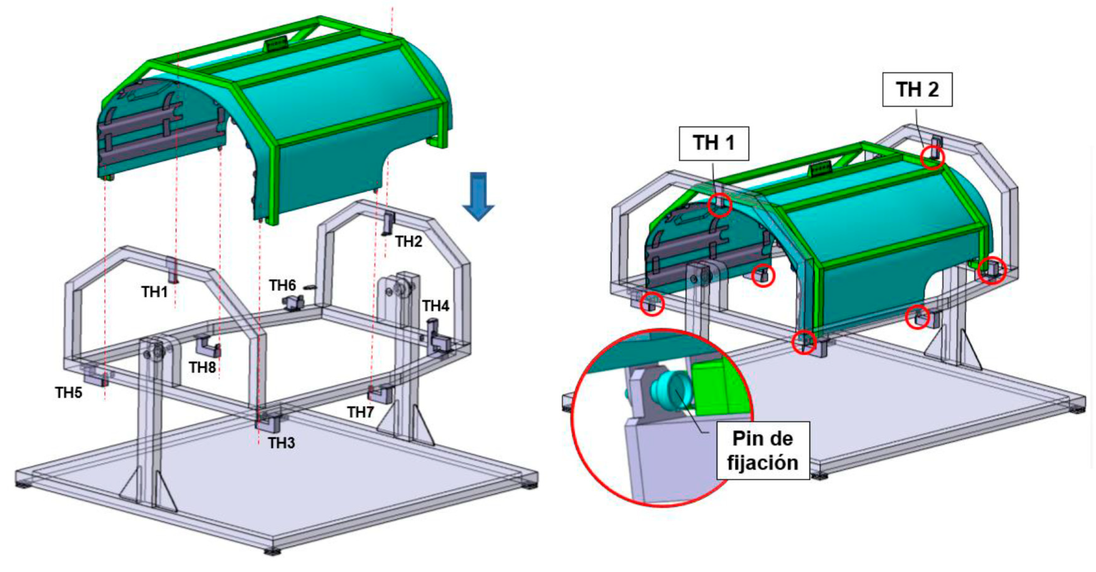
The overall dimensions of the ARE prototype are approximately 3 m × 2.2 m × 1.2 m. In all cases, except for the skin, the local reference system is defined by some specific Tooling Holes (THs) realized as measuring points. The datum plane is defined by 3 points (TH1, TH2 and TH3), the secondary axis is defined by TH1 and TH2, and the coordinate system’s origin is defined by TH1. In the case of the composite skin, the reference system shall be defined with the origin (TH1), the main axis (TH1 to TH2) and 6 additional TH lugs (TH3/TH4/TH5/TH6/TH7/TH8) along the longitudinal edges that shall be used to get the best-fit position (see
Figure 2). The real demonstrator integrates the following main parts where those TH points are physically considered:
-One (1) high-integrated composite skin, including the co-cured omega stringers and co-cured contour frames. The composite skin is depicted in
Figure 2.
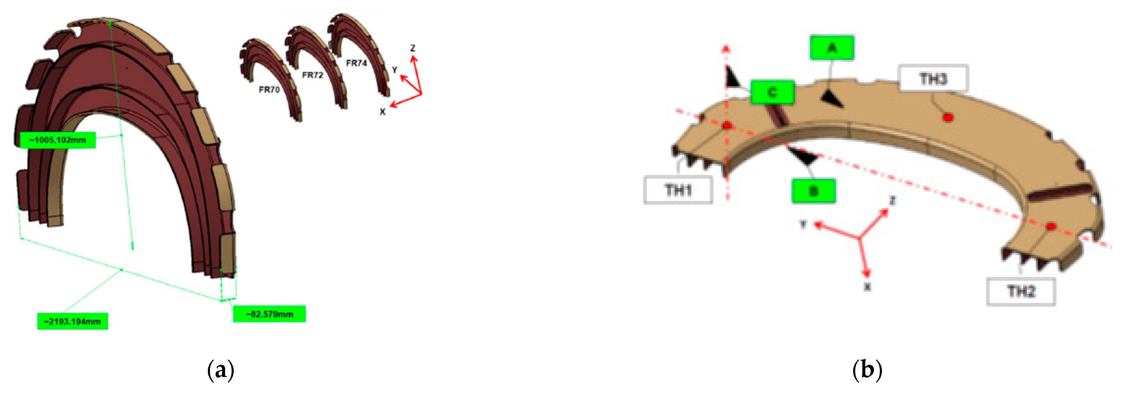
-Three (3) high-load composite frames (FR70, FR72, FR74). These parts shall be assembled according to the novel assembly method and shall be compared against the traditional method. The composite frames (FRs) are shown in
Figure 3.
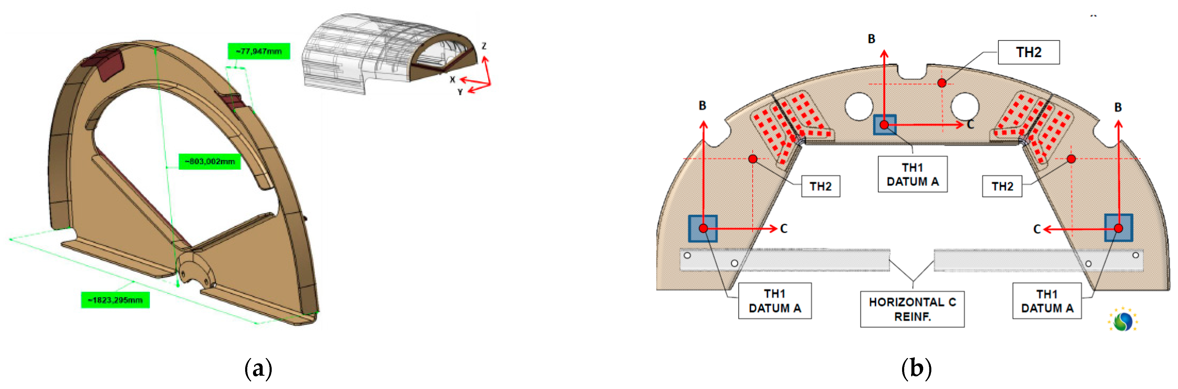
-One (1) closing additive frame. This part is manufactured by thermoplastic tooling and it is depicted in
Figure 4.
-Two (1 + 1) “H” shape composite beams. They are shown in
Figure 5.
3.2. Description of the Main Tooling
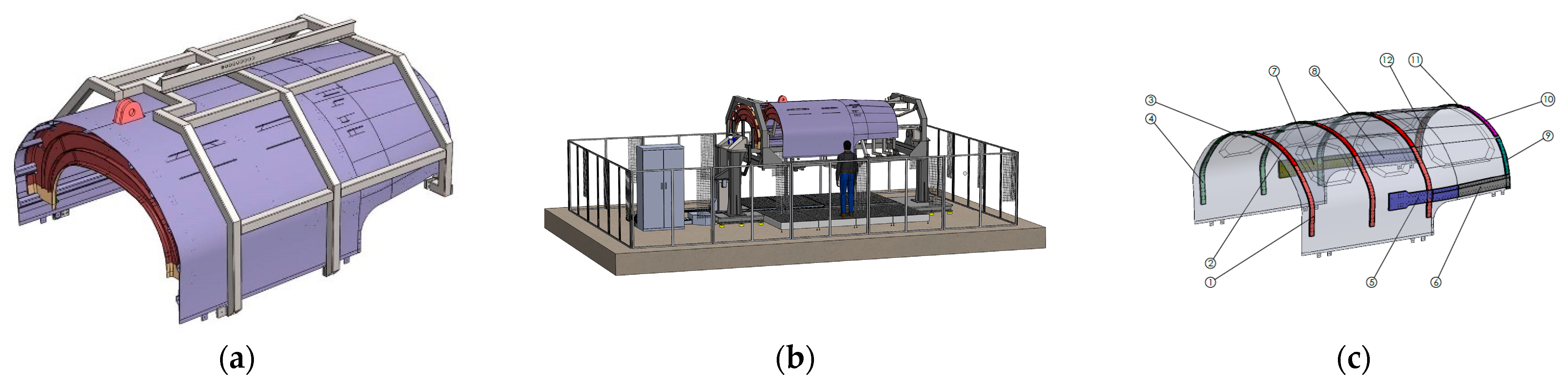
Aiming to realize a metrology-driven assembly process, a novel tooling set is envisaged. The development includes the complete tooling lifetime, from the design stage to the prototype manufacturing and assembly stages. The tooling set is divided into several functionalities and operations where 3 main toolings can be distinguished as explained in
Figure 6.
- (a)
Skin and product manipulation tooling: sling structure.
- (b)
Assembly tooling: composed of the main structure and supporting fixtures as well as the automatic stages.
- (c)
Drilling tooling: drilling templates.
Although all of the previously presented tooling set is needed to perform the assembly process, the article focuses on the assembly tooling which plays the role of locating and joining all the components that comprise the ARE fuselage component. It covers not only the mechanical tooling (manipulation sling and drilling templates) but also the interaction, management and control over the integrated control systems (drives, force/torque sensors, displacement sensor, external measuring system, etc.) during the assembly process.
In the following lines, the main parts and functionalities of the assembly tooling are described briefly.
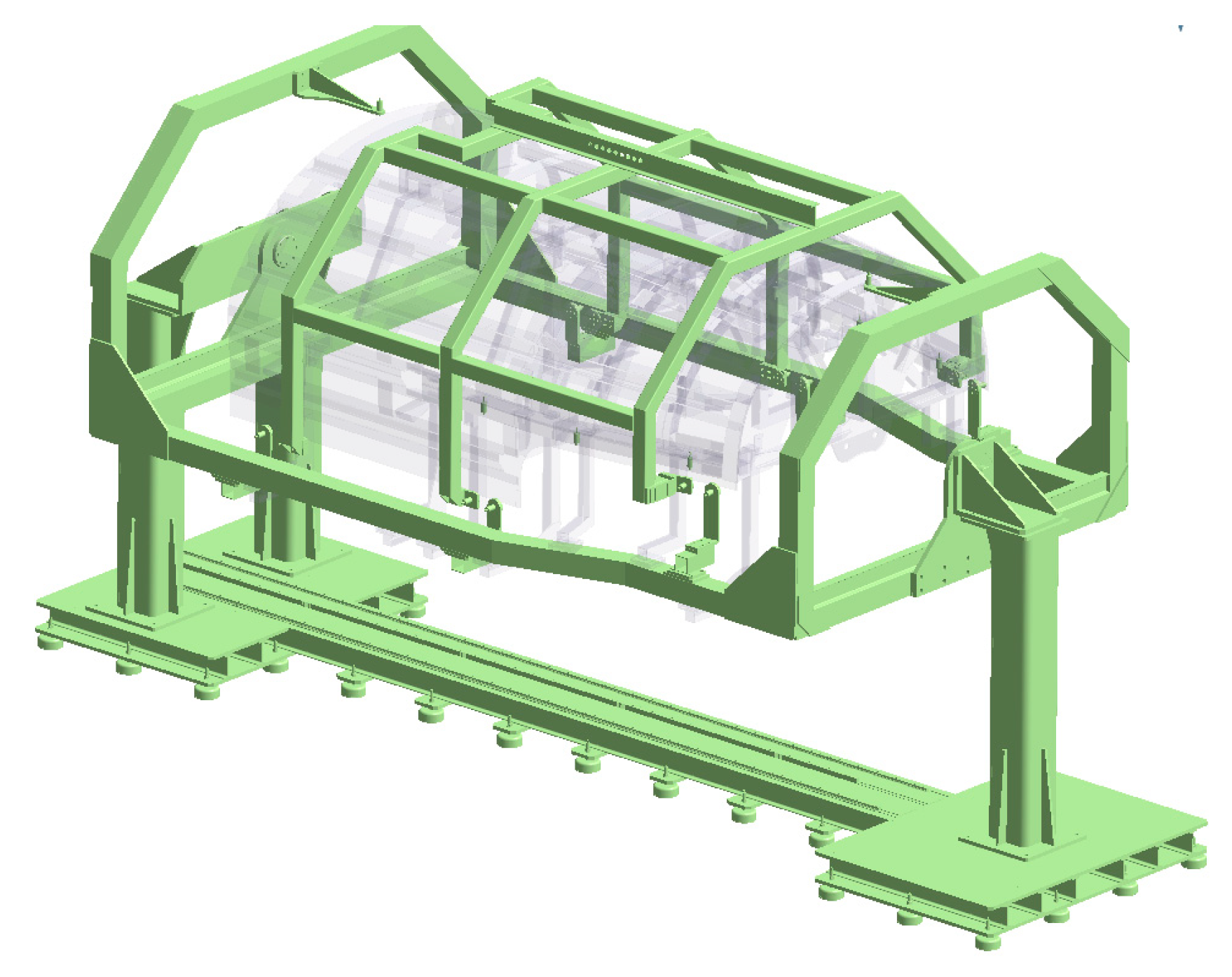
-Main structure (highlighted in green): The skin is located and attached to the main structure (see
Figure 7 where sling structure is included). The nominal geometry shall be ensured by the adjustment of fixing lugs (TH points) through chocks, studs and resins. This is the main frame of the assembly tooling which must remain stable during the complete assembly process to maintain the tooling stiffness.
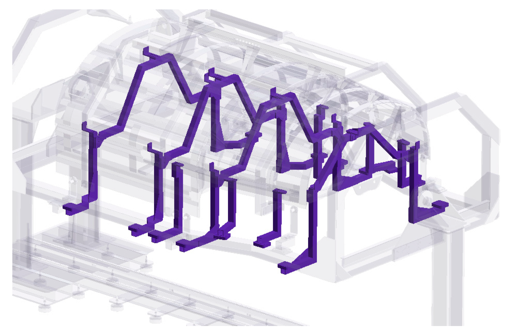
-Auxiliary/secondary tooling: The frames (load and closing) and the “H” shape composite beams are located and fixed to the secondary tooling (see
Figure 8). Similarly to the main structure, the geometry of such fixtures (6×) will be metrology-driven to meet the nominal geometry within the ARE fuselage assembly.
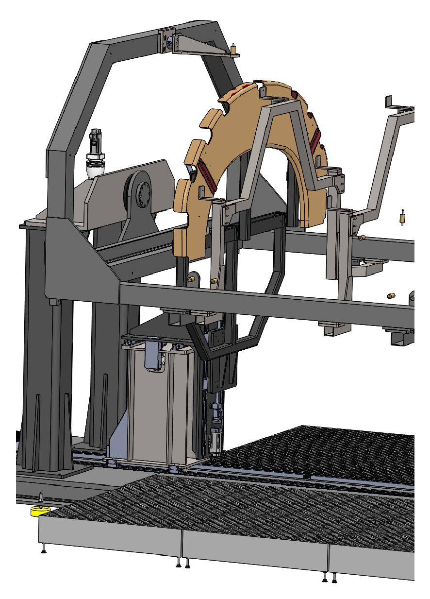
-Mobile fixture: It aims to move and locate the load frames within the auxiliary tooling (see
Figure 9). This mobile fixture will be fed and commanded by the external metrology framework as explained later in this paper.
Following this, the integrated control systems included within the tooling assembly are performed.
-Process monitoring sensors (positioning, an anticollision system, force and torque sensors): Force and torque sensors shall be integrated into the main tooling structure to monitor the reaction loads on the TH1 and TH2 lugs. Moreover, the limit positioning sensor switch shall be integrated into the mobile fixture while the motion origin shall be adjusted during the tooling assembly set-up. Moreover, the assembly machine will include a non-desired object detection system to avoid the collision of the mobile parts and components through the assembly process.
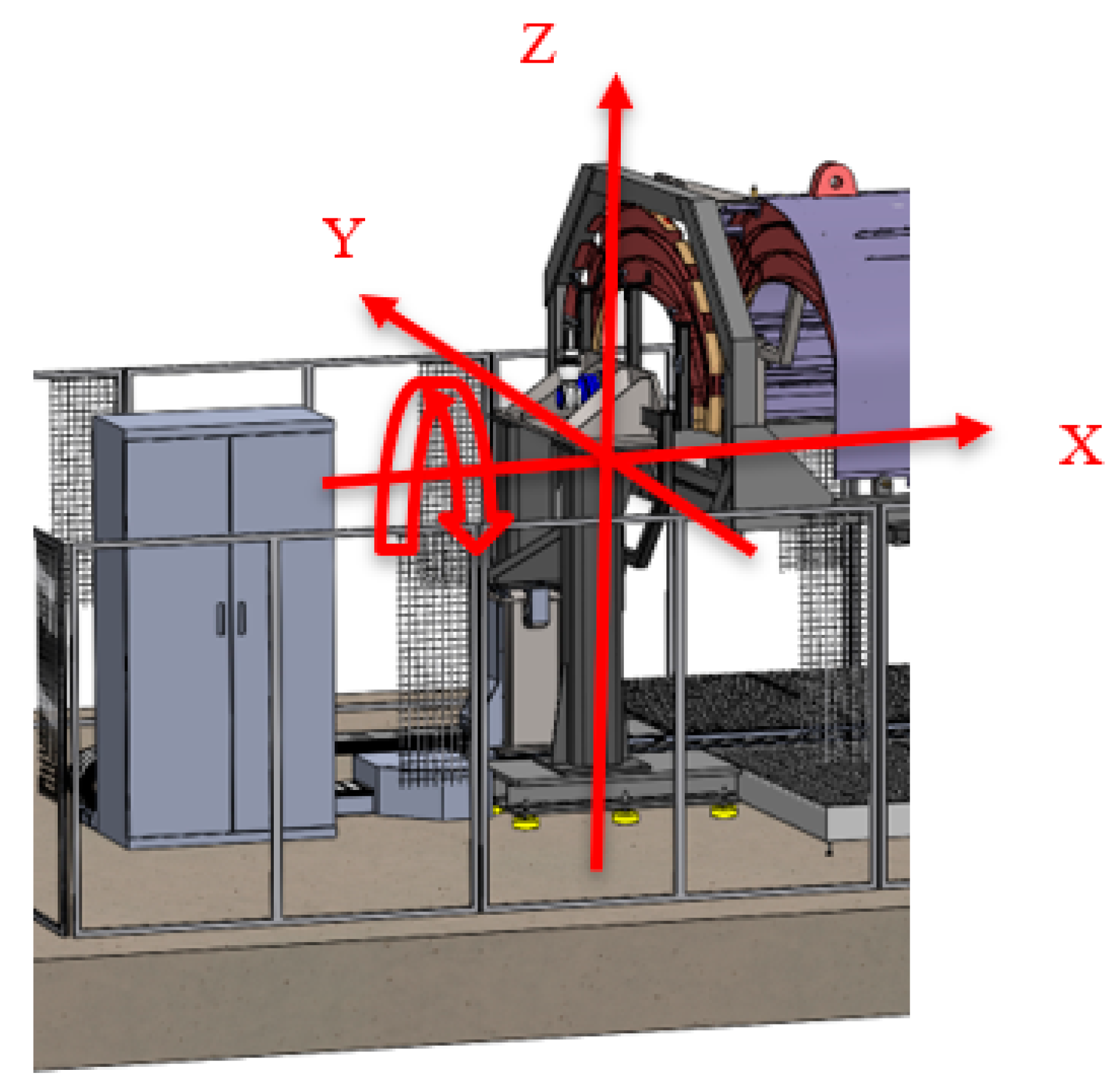
-Positioning drives and transmission systems (linear and turning stages): Three linear stages (XYZ) and a turning stage (Rx) are suggested to ensure the automatic tooling assembly process of every component, except for the closing frame and the “H” shape beams that are mounted manually (see
Figure 10). The linear stages shall move the mobile fixtures to locate the load frames in their nominal position while being commanded by a metrology-driven approach. A laser tracker instrument is employed to bring every component to its nominal position. In addition to the laser tracker instrument, the end limit travel range of the largest axis (X longitudinal axis) for each frame position shall be controlled by a Linear Variable Differential Transformer (LVDT) system to guarantee that moving frames do not collide with the fixed supports while reaching their nominal position. Concerning the turning stage (Rx), it will enable the turning of the ARE fuselage to allow performing the operations that require it (mainly drilling and riveting tasks). Thus, an extra angular encoder is introduced within the turning stage to ensure an accurate angular origin (0° position) realization.
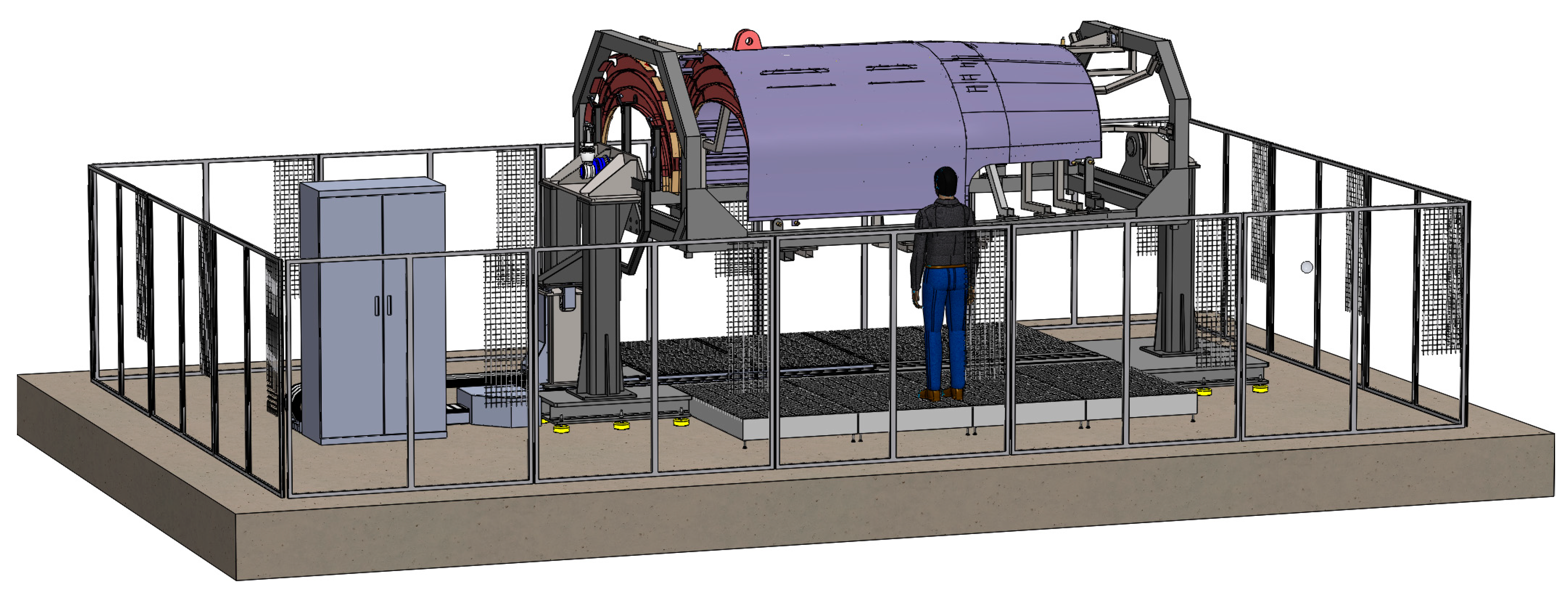
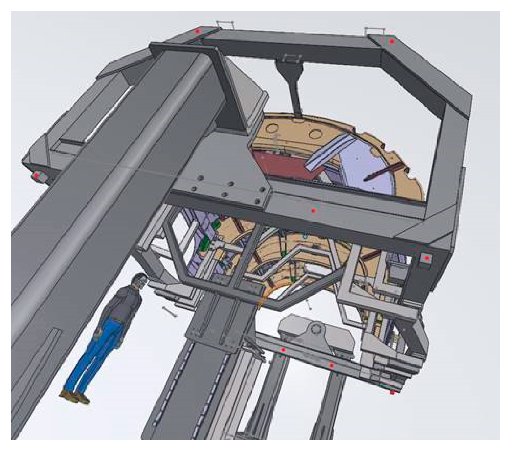
Considering the collaborative approach for the tooling, ergonomics shall also be considered within the design of the novel tooling. In this way, the maximum and minimum heights, the tooling accessibility (inner and outer side) and the tooling operation modes shall be considered to aid the operators during the assembly process. The main dimensions and layout of the tooling cell are depicted in
Figure 11.
3.3. Description of the Assembly Sequence
This chapter describes the main steps of the ARE fuselage assembly process. The presented sequence is a basic simplification of the real process, which is much more complex, aiming to highlight the virtual assembly simulation process within the overall assembly process. The temporary fixing of elements is performed by Cleco fasteners whilst the more critical joining points are ensured by accurately manufactured pins. The ARE fuselage assembly process is described in the following points:
- 1
Skin component positioning in the assembly tooling: This is the operation during which the skin component is manually positioned on the main structure of the assembly tooling aided by a crane.
Figure 12 represents the assembly operation where the sling releases the skin component on the main structure by locating it through the reference TH points. The fixing operation is performed by the fixing pins.
- 2
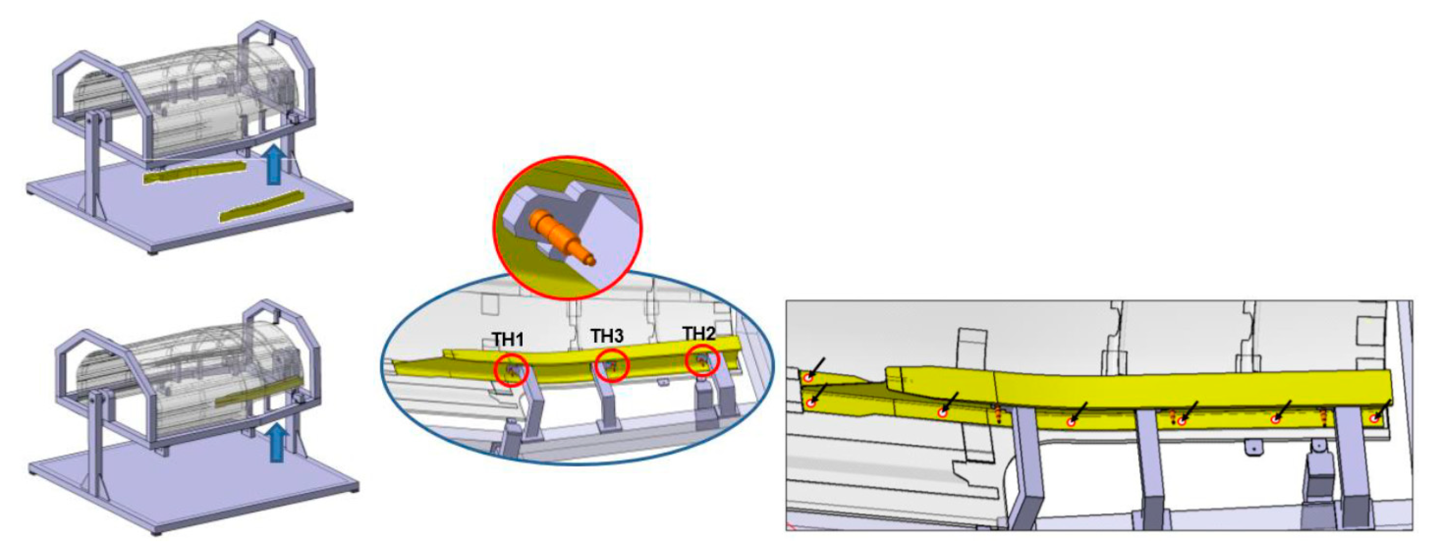
The “H” shape composite beams positioning: This is a manual operation during which the “H” beams are positioned on the main structure through the TH1, TH2 and TH3 supports. The temporary fixing is realized by Cleco fasteners and several coordination holes (CHs) are transferred into the skin where more Cleco fasteners are employed for a correct fixing operation.
Figure 13 depicts the “H” composite beams positioning operation on the skin component.
- 3
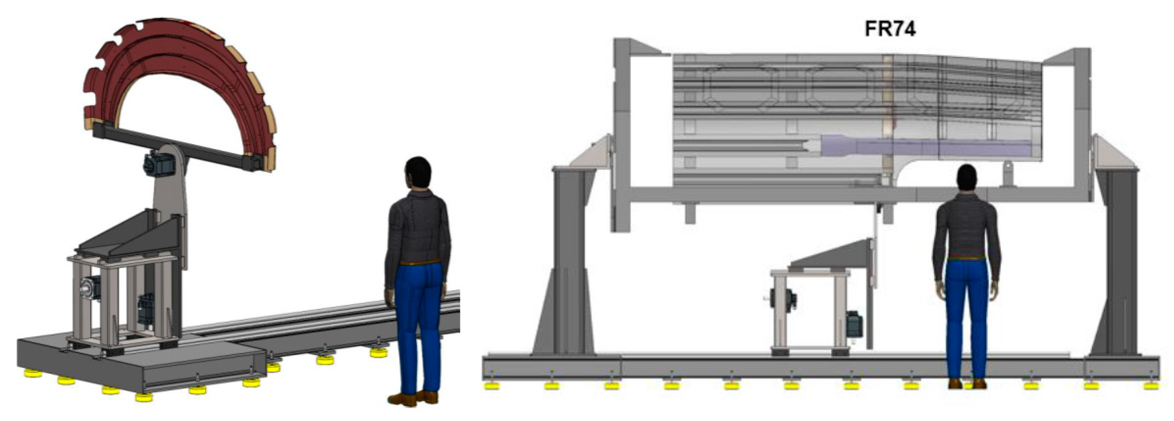
Load frame components positioning: This operation realizes the automatic positioning of each load frame (LF) into their supporting auxiliary tooling attached to the main structure. The mobile carriage sequentially brings every LF to their position wherein they are fixed to a supporting fixture. Initially, frame 74 (FR74) shall be positioned and fixed, then frame FR72 and finally frame FR70. The moving stage shall be metrology-driven by an externally placed laser tracker instrument while the LVDT sensors realize the end-of-limit positioning for each frame.
Figure 14 shows the mobile carriage and the assembly of a frame.
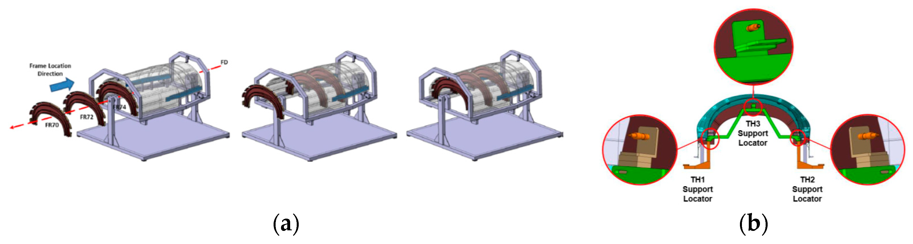
The previously mentioned supporting fixture (in green in
Figure 15b), which is also manually and sequentially mounted onto the skin, plays an important role within the main tooling, enabling the coupling between the LFs and the skin.
Figure 15 represents how the FRs are mounted in flight direction as well as how they are positioned and fixed through three TH points and Cleco fasteners.
- 4
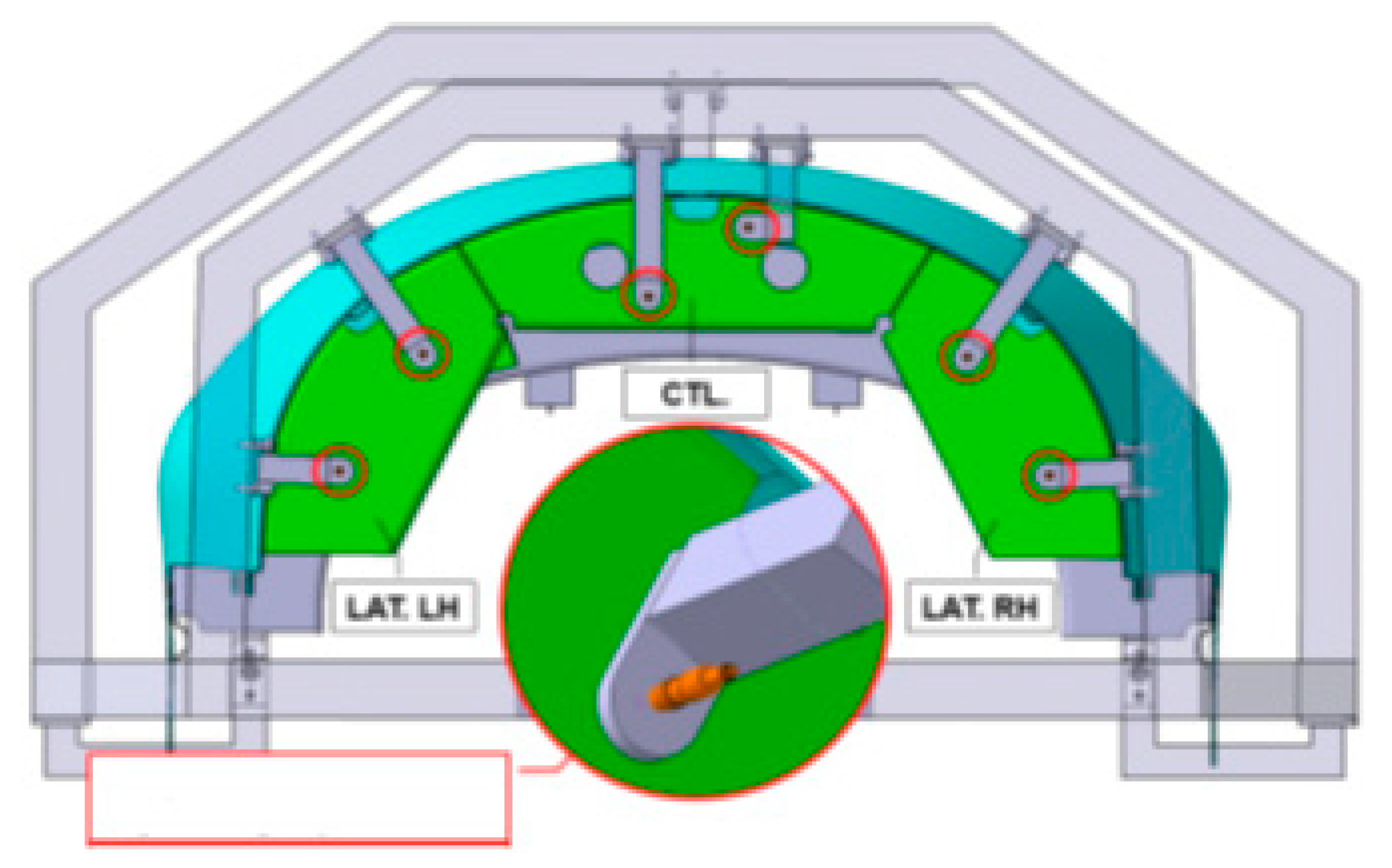
Positioning and drilling of the closing frame sub-assembly: This operation realizes the manual assembly and final location of the closing frame assembly. The closing frame is composed of several parts, the so-called central and lateral left-right components (LH-RH) that are joined into the main structure by the integrated fixed supports. These components are located by TH points and fixed by Cleco fasteners. Once the components are mounted, the coordination holes are transferred into the skin component and additional Cleco fasteners are used for a robust fixing.
Figure 16 shows the assembly and fixing of the closing frame.
3.4. Description of the Simulation Workflow
In the following lines, the virtual measuring approach and the simulation environment are introduced.
3.4.1. Introduction of the Measuring and Simulation Concepts
The metrology-driven approach that guides the assembly operator during the assembly process consists of an external metrology frame and a specific measurement procedure. The proposed technology is a portable coordinate measuring machine (PMMC), the so-called laser tracker (LT) instrument. The 3D accuracy of LT instruments is defined by U (k = 2) = 15 µm + 6 µm/m [
17] according to ISO 10360-10:2016 Standard [
17]. This PMMC measures the 3D coordinates of a retroreflector located on the measurand (component or structure). Combining the measurements of at least 3 points (usually, more than 3 points are recommended), the spatial orientation and position of a body (6 degrees of freedom (dof)) shall be established regarding a specific reference (measuring system, other part or even the world coordinate system). Thus, this measurement information shall be used to assist the assembly tasks and guidance purposes wherein an accurate part positioning and assembly is required.
For the ARE fuselage assembly process, several components such as the composite skin and the load frames demand an accurate assembly process on the plane reference system (global coordinate system). To do that, several nominal coordinates shall be defined from the very beginning within an initial manual referencing process, allowing those nominal points to be used as target points during the assembly process. Thus, the spatial deviation of each target point shall be monitored, guiding the operator during the manipulation of the ARE fuselage components to ensure the final assembly. In this way, the results of the measurement of three or more reflectors shall indicate the 6 dof of the component under the measurements concerning the active reference system aiming the assembly of the skin with the frames. The result of those measurements is converted into commands for the automatic stages that shall bring every component to the final position within the assembly. Thus, a closed-loop assembly process shall be conducted.
Aiming to predict the most suitable measuring approach (fast, simple and accurate enough) within the ARE assembly process scenario, an a priori metrology simulation is suggested. To do that, a digital twin of either the assembly process (components, tooling) or the measurement system is developed within a simulation framework, so the complete measurement sequence is materialized in simulation mode. In this case, the Spatial Analyzer (SA©) inspection software provides several powerful simulation tools such as running instruments in simulation mode, planning the placement of measurement instruments or checking the visibility of target points within a digital measurement scenario so that a fit-for-purpose measurement procedure is designed, reducing to a high extent the metrology-driven set-up process.
3.4.2. Design of the Measurement Set-Up
One of the most critical aspects of the metrology-driven solution designing process is to define an appropriate location of the measurement instrument and the target points aiming to (a) avoid occlusions and (b) obtain accurate measurements. The relative position among them describes the measuring scenario set-up and consequently determines the measuring procedure’s performance and scope (see
Section 3.4.3).
Aiming to design a virtual measurement scenario, establish a suitable measuring plan and define a specific measurement configuration, an iterative process is established as explained here:
A new simulation session is opened within SA© software.
A computer-aided design (CAD) of the ARE assembly is imported. The CAD model includes either the components’ geometry or tooling geometry.
The measuring instrument model is connected in simulation mode. It includes a virtual error model of the previously mentioned LT instrument’s 3D accuracy.
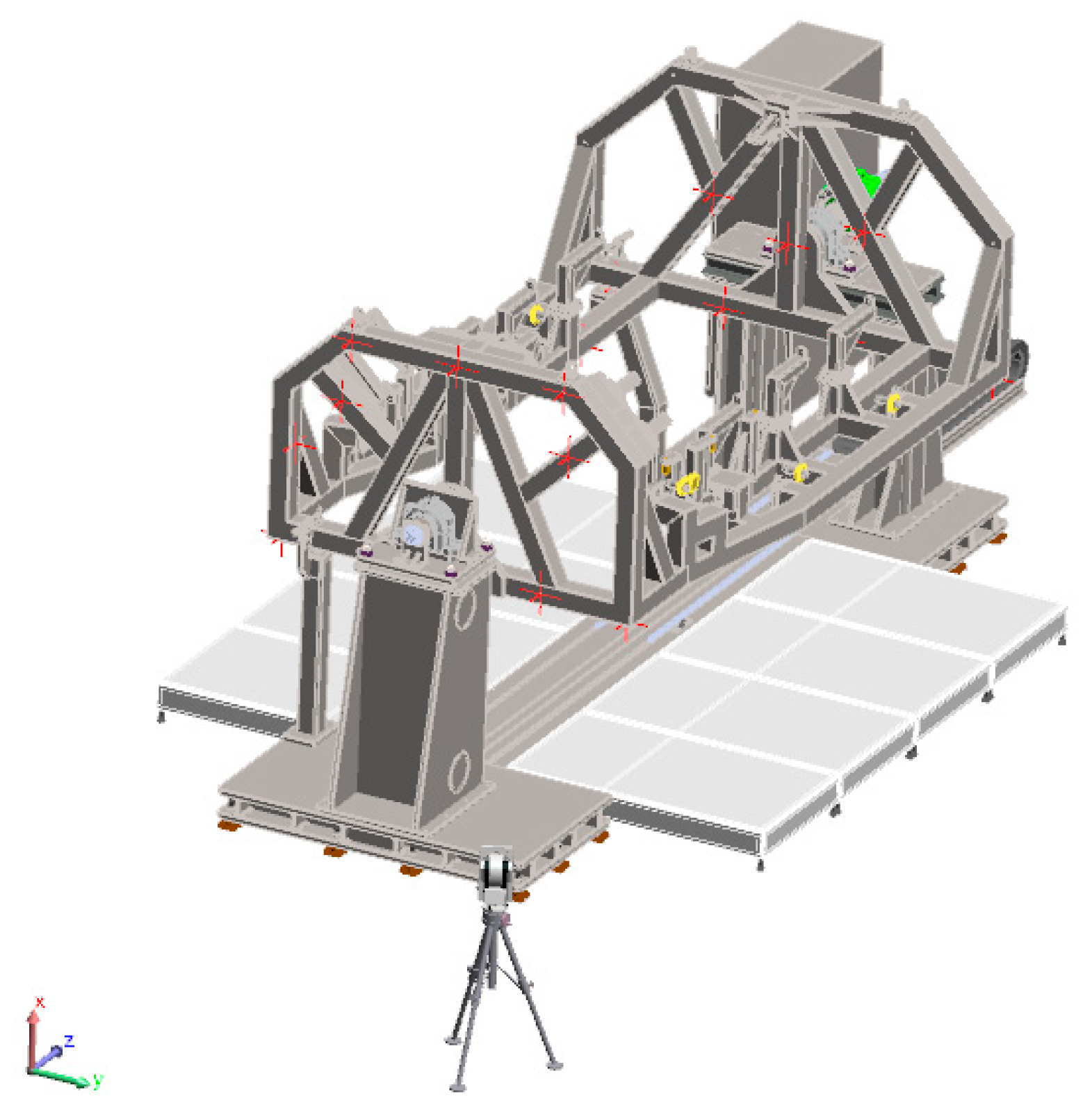
Figure 17 represents the simulation environment including the ARE product, the tooling and the LT instrument.
- 4.
According to the metrology technician’s experience, an initial spatial location of the LT measuring device is defined (initial guess).
- 5.
The number of target points and their distribution are identified aided by the main tooling CAD. Aiming to obtain a measurement uncertainty that is as low as possible, target points are volumetrically distributed along the XYZ dimensions of the jig structure. At this point, the target points are defined for both the main tooling (fixed points) and the moving stage that brings and locates the load frames.
- 6.
According to the measurement scenario defined within the simulation environment, an initial measurement of the target points is realized manually with the LT instrument. Thus, virtual XYZ coordinate measurements are fabricated within the simulation environment. This initial measurement allows for the updating of the initial LT instrument measurement uncertainty error model defined by the LT manufacturer. The LT error model includes both the systematic and the random error components.
- 7.
At this moment, the line-of-sight from the LT location to the target points shall be verified to determine if every target point is reachable from the LT location.
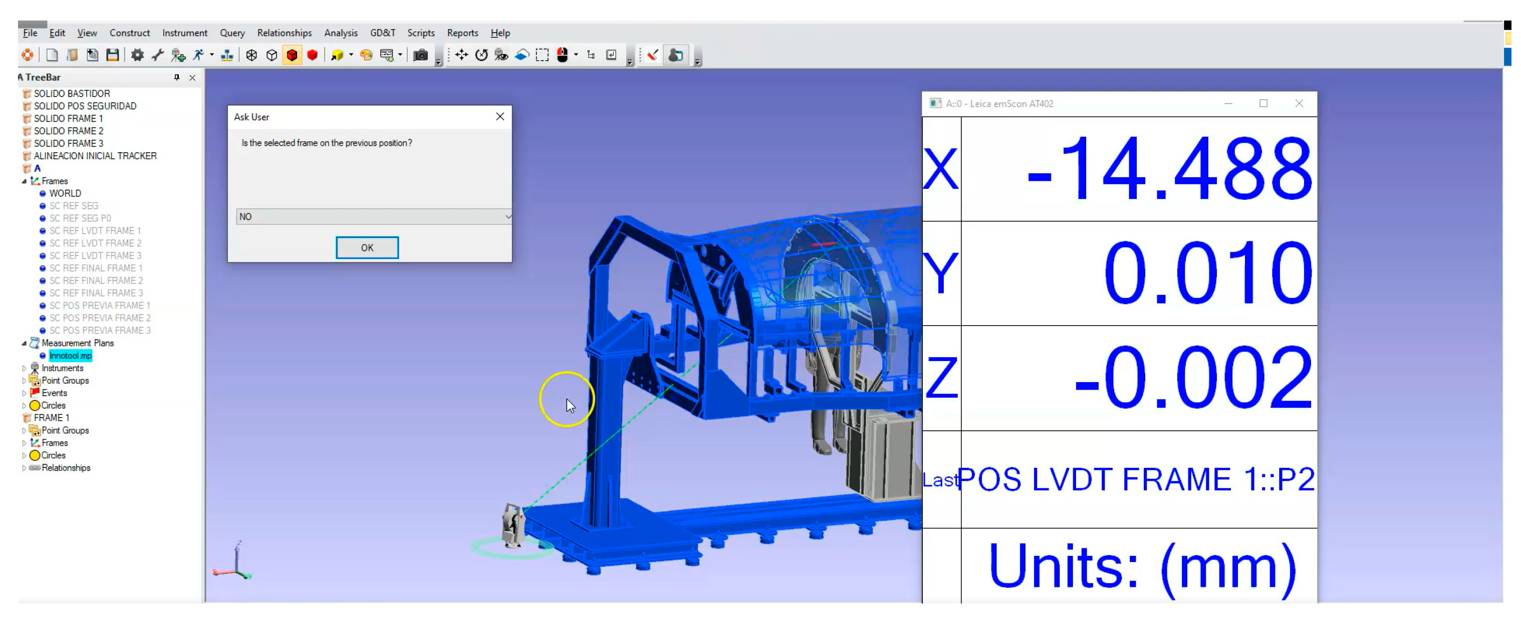
Figure 18 presents the line-of-sight simulation process wherein the target points to be measured are highlighted in red.
- 8.
Once the LT error model is updated according to those initial measurements realized in step 6, an a priori Monte Carlo simulation shall be performed to predict the measurement uncertainty within the real assembly scenario. The Monte Carlo simulation is conducted according to the JCGM 101:2008 technical recommendation [
18], which suggests materializing an iterative simulation process of the previously measured points by introducing a statistical error to the LT error model [
19]. Hence, it allows an understanding of the influence of error on the defined virtual measurement scenario.
- 9.
Simulation results are obtained and summarized aiming to (a) characterize the measurement uncertainty, and (b) the target point visibility.
If results are under compliance (uncertainty values below 0.15 mm), the same LT configuration is considered for the rest of the load frames, which means repeating steps 2–9 for every load frame.
If results are not as good as expected, the LT location is changed and all the previous simulation steps are repeated until a suitable LT position is found.
- 10.
Once the LT location and target points distribution is validated, the target point information (position and orientation) allows the integration of the physical retroreflector nests into the main structure and moving fixtures.
- 11.
During the tooling commissioning stage, the real position and orientation of every target point shall be measured and recorded as a nominal value for the automating of the data acquisition process of the following measuring tasks.
3.4.3. Simulation of the Metrology-Driven Measuring Procedure
Once the a priori simulation is realized and the LT and target points position are validated, a similar simulation process shall be executed to estimate the real-time position and orientation of the mobile load frames within the ARE assembly process. This specific simulation enables estimating the measurement uncertainty for each of the mobile carriage poses (position and orientation) which allows evaluating the fit-for-purpose quality of the metrology-driven solution.
As previously explained, the JCGM 101:2008 guide (evaluation of measurement data—Supplement 1 to the “
Guide to the expression of uncertainty in measurement”—propagation of distributions using a Monte Carlo method) describes practical guidance on the application of Monte Carlo simulation for the estimation of uncertainty in measurement [
18]. For the present work, this guide is employed to determine the measurement uncertainty within the simulation environment. Here, the specific approach for the measurement uncertainty estimation is to conduct a rigid body transformation between the simulated points (real) and the nominal reference points according to the Monte Carlo method. In total, 1.000 iterations are performed for a suitable propagation of the error distribution model, so the standard deviation of the rigid body transformation parameters is obtained and included within the expanded measurement uncertainty result.
Figure 19 shows the pose measurement uncertainty estimation process.
4. Results
The measurement uncertainty results simulated in Chapter 4 are presented here. Initially, the obtained results according to the location and orientation of either the LT instrument or the target points to the ARE assembly layout and the considered coordinate system are shown. Then, the results for the “real-time” assembly process of the load frames components are described. In particular, the results for the FR74 component are shown, due to the fact that it is the most critical component during the simulation as it is placed in every position of the insertion trajectory, including the fixed locations of FR70 and FR72.
4.1. Simulation Results on the Measuring Set-Up Definition Process
As an overall accuracy request, the geometric accuracy of the main tooling must remain below 0.15 mm for the different FR positions, and therefore the metrology-driven solution shall ensure an accuracy 3 to 10 times better (20–65 µm) to meet manufacturing tolerances according to ISO 14253-1 Guide to the “
decision rules for proving conformity or nonconformity with specifications” [
20]. To meet those accuracy requirements, the simulation tool makes it possible to run an iterative process that looks for the best configuration for the LT and targets points.
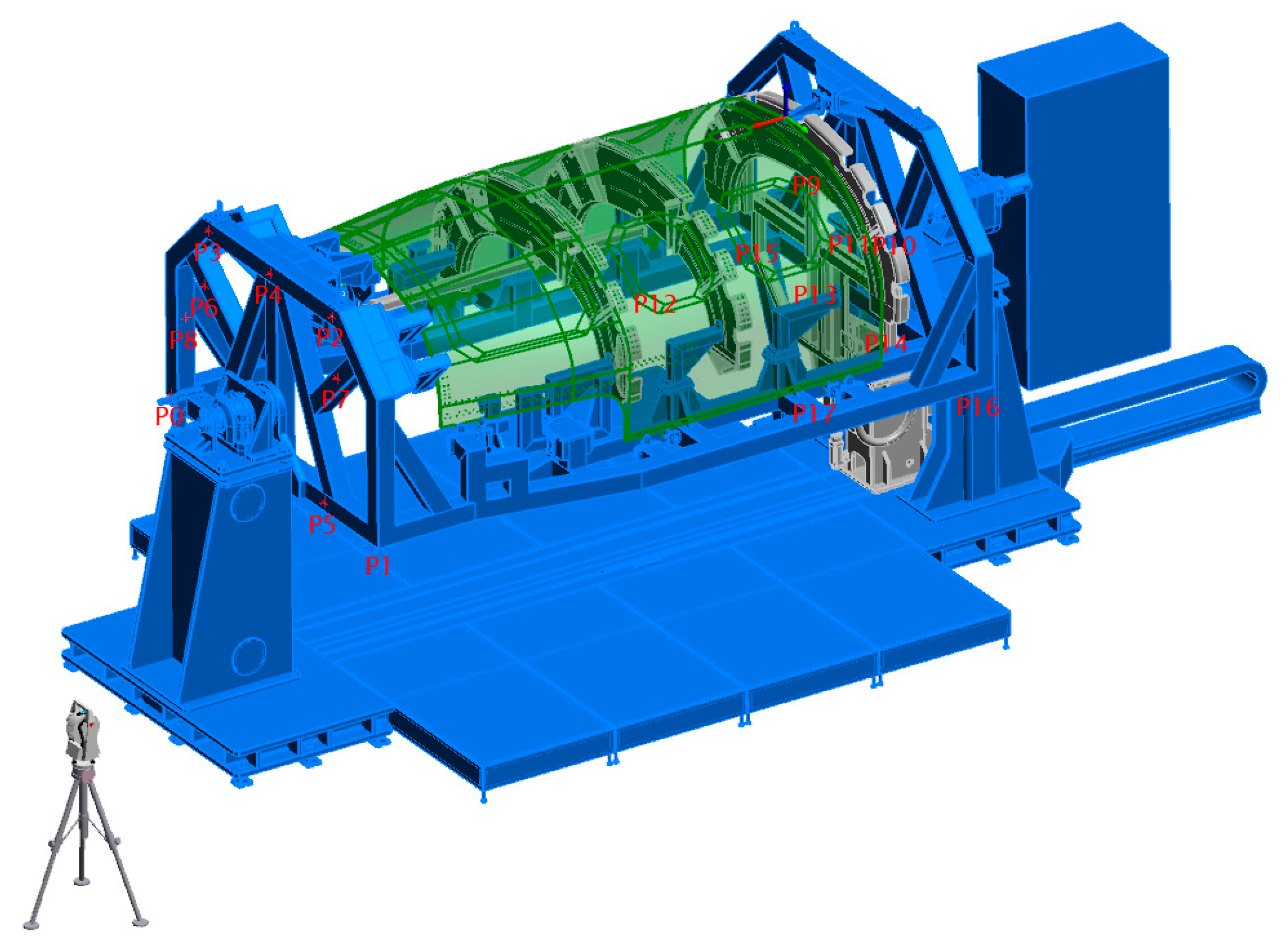
After conducting multiple simulations, it is concluded that the most suitable LT location is as depicted in
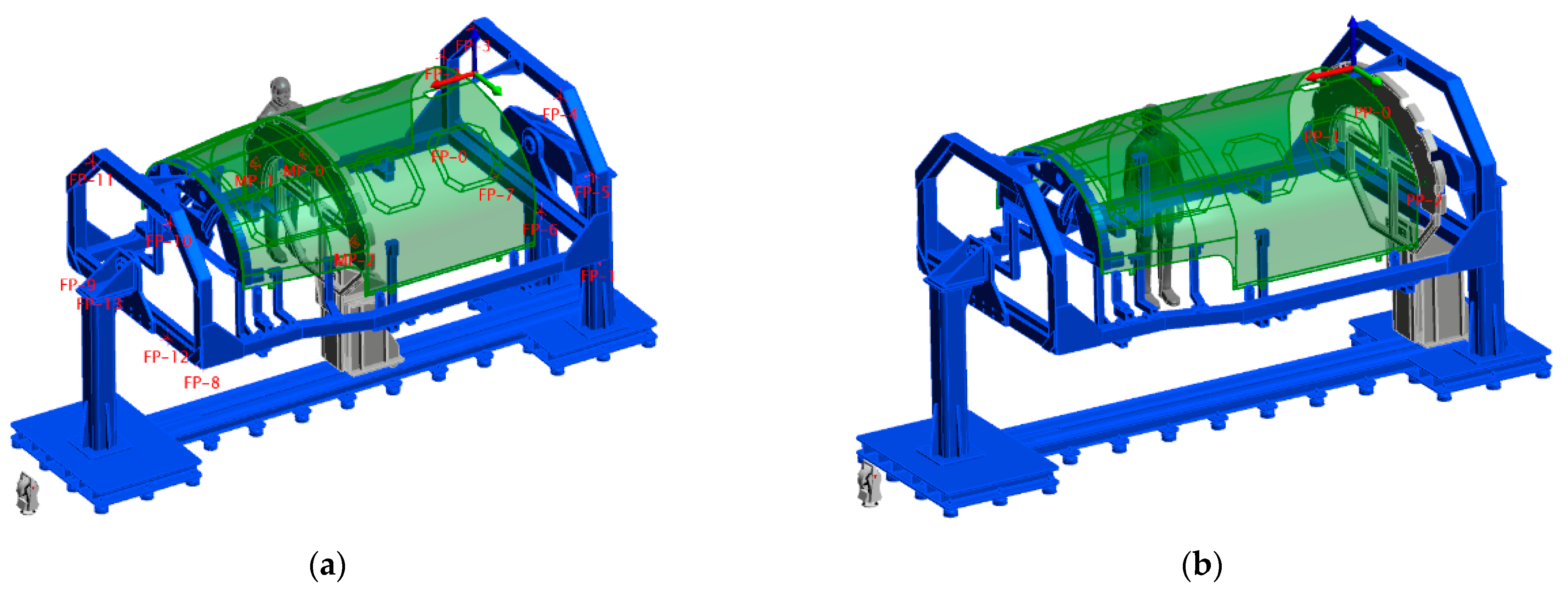
Figure 20. The obtained layout enables measuring multiple target points located in the tooling such as the fixed points (FPs), the mobile points (MPs) and the parking points (PPs). It shall be highlighted that a coincident location of the LT with the turning axis has been considered during the simulation, but the obtained results show that the visibility of several target points is considerably reduced. Concerning the location of the batch of target points, 20 points are volumetrically distributed as a result of the simulation. A total of 17 out of 20 points are attached to the main structure and the remaining 3 points are fixed to the mobile carriage.
Figure 20 shows the target point distribution.
Regarding the measurement visibility of those target points,
Figure 21 shows the result for the performed line of sight analysis. Here, the most critical assembly process step is shown, wherein FR74 and FR72 are already located, which makes it more difficult to ensure the visibility of MPs for the FR70 position. However, no limitations are foreseen as depicted in
Figure 21.
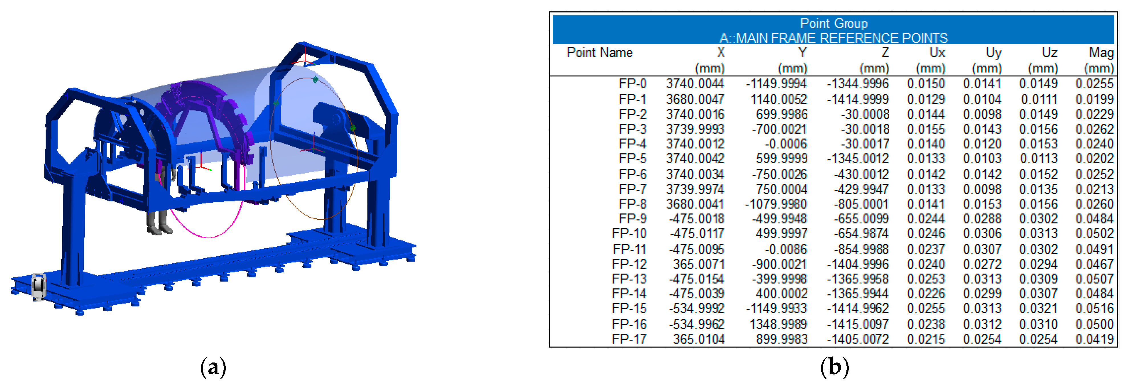
The achieved expanded measurement uncertainty (U) for the target points is about 50 µm (k = 2) (see
Figure 22). Thus, the accuracy request for the tooling metrology-driven solution is met within the simulation environment.
4.2. Simulation Results on the Metrology-Driven Assembly Process
A similar simulation framework is established to develop and evaluate the metrology-driven assembly process for the frame composite components. As explained before, the FR74 is the most critical component within the assembly process since it is placed in every position of the insertion trajectory, including the fixed locations of FR70 and FR72. The obtained simulation results are explained through several tables.
Table 1 represents the nominal FR poses (position and orientation) and values.
Table 2 depicts the obtained simulation results for those FR poses and their measurement uncertainty data. The data consider several FR74 positions during the insertion process through the skin component. Some of these positions coincide with the fixed locations of the FR72 and FR70 components, and therefore these positions are considered points of interest within this evaluation. The measurement uncertainty values are estimated for a level of confidence interval of 95% (k = 2).
Finally,
Table 3 shows the deviations between the nominal and simulated FR poses, assessing the systematic error contribution of the metrology-driven assembly process. The results show that the simulation results are below the accuracy request (0.15 mm for position), and therefore it is demonstrated that the measuring set-up, as well as the developed metrology-driven solution, are suitable for their practical implementation.
The results shown in
Table 3 demonstrate that the measuring approach meets the assembly demands in terms of accuracy for the different fixing locations of the FR components. The systematic deviations are below 0.017 mm for the translation values and below 0.001° for the orientations, while the measuring uncertainty values traduced to rigid transformation values are on average 0.1 mm (for U
Tx, U
Ty, U
Tz) and 0.0035° (for U
Rx, U
Ry, U
Rz).
5. Conclusions and Future Work
This article introduces the MAA approach within the traditional assembly process of the ARE fuselage component. It shows a practical implementation of a metrology-driven solution for the assembly of an aeronautical assembly, making the process more accurate, faster, repetitive, automatic and collaborative in terms of aided-load handling. The article suggests a simulation environment that enables predicting the performance of a certain measuring set-up within the ARE assembly scenario. The digital twin of the complete measurement scenario, including the tooling, the aeronautical components and the metrology-driven solution, makes it possible to conduct an a priori metrology simulation. Thus, the most appropriate measuring approach is predicted in advance, considering aspects such as the most appropriate location of the LT instrument, the visibility of the target points and the achievable measurement uncertainty for the XYZ coordinates of target points as well as the position (XYZ) and orientation (RxRyRz) of the FR components to be assembled. The obtained measurement uncertainty values are compared with the ARE assembly specification and the results are under specification. This way, the metrology-driven solution is validated to be fit-for-purpose.
The future work that is currently being executed is the physical realization of the ARE prototype. In addition to all the advantages obtained from the simulation work, mainly focused on the prediction of the most appropriate metrology-driven solution, it shall be highlighted that the measurement workflow within the physical ARE prototype shall be realized with the measurement procedure developed within the simulation environment. In this manner, the same simulation solution can be used and updated for the real performance scenario, which means that a comparison shall be run between the a priori and posterior information. However, few differences are expected within the real implementation. One of the aspects that may directly affect the performance of the real implementation of this metrology-driven solution shall be the accurate characterization of the fixed reflectors located in the main structure and the mobile support. This measurement shall be performed once the main tooling components are assembled into the ARE fuselage. The realization of the target points shall be performed with the Reflectors for Fixed Installation (RFI) type of fixed reflectors and the so-called TBR type reflectors for the mobile components. Whilst the fixed reflectors are always seen from the same perspective, the mobile reflectors change their viewing angle, which requires specific retroreflectors that assume such angle variability. A second possible aspect is the potential deviation of the real scenario from the simulated one, which implies a potential deviation within the retroreflector line-of-sight analysis.
Concerning future work, TEKNIKER will keep studying how to implement the real-time uncertainty assessment tool through the improvement of the simulation framework. At the moment, an offline measurement uncertainty assessment is estimated, although the tracking of the load frame insertion operation is enabled in real-time by the LT instrument. Further optimization aims to also include this uncertainty evaluation capability in real-time, which implies to adapt the Monte Carlo-based iterative approach driven by more efficient computing approaches.


