Review

Pumped Thermal Energy Storage Technology (PTES): Review

School of Mechanical and Design Engineering, University of Portsmouth, Portsmouth PO1 3DJ, UK
*
Author to whom correspondence should be addressed.
Thermo 2023, 3(3), 396-411; https://doi.org/10.3390/thermo3030024
Submission received: 26 May 2023 / Revised: 26 June 2023 / Accepted: 6 July 2023 / Published: 11 July 2023
(This article belongs to the Special Issue Feature Papers of Thermo in 2023)

Abstract

:
In recent years, there has been an increase in the use of renewable energy resources, which has led to the need for large-scale Energy Storage units in the electric grid. Currently, Compressed Air Energy Storage (CAES) and Pumped Hydro Storage (PHES) are the main commercially available large-scale energy storage technologies. However, these technologies are restricted geographically and can require fossil fuel streams to heat the air. Thus, there is a need to develop novel large-scale energy storage technologies that do not suffer from the abovementioned drawbacks. Among the in-development, large-scale Energy Storage Technologies, Pumped Thermal Electricity Storage (PTES), or Pumped Heat Energy Storage, stands out as the most promising due to its long cycle life, lack of geographical limitations, the absence of fossil fuel streams, and the possibility of integrating it with conventional fossil-fuel power plants. There have been a number of PTES systems proposed using different thermodynamic cycles, including the Brayton cycle, the Rankine cycle, and the transcritical Rankine cycle. The purpose of this paper is to provide a comprehensive overview of PTES concepts, as well as the common thermodynamic cycles they implement, indicating their individual strengths and weaknesses. Furthermore, the paper provides a comprehensive reference for planning and integrating various types of PTES into energy systems.

1. Introduction

Renewable sources of energy have become increasingly employed in recent years, in particular wind power and solar photovoltaic technology. The overall aim of this has been to decarbonise the energy sector. The International Energy Agency (IEA) reported that, in 2020, 29% of the electricity generated worldwide came from renewable sources [1]. It is predicted that this percentage will rise to 49% by 2030 [2]. One of the main drawbacks of renewable energy sources is that they are unable to supply power in a reliable and stable manner, as their sources are intermittent. This means that there is often a misalignment between the amount of energy being generated and the demand via the grid. One of the ways to mitigate this challenge is through the use of energy storage systems [3].
They can offer large-scale energy storage and have a number of advantages: their operational lifetimes are long; energy losses are low during storage; they are not subject to the same geographic limitations; and they offer a high volumetric energy density [4].
Pumped thermal energy storage (PTES) is a highly promising and emerging technology in the field of large-scale energy storage. In comparison to the other thermal energy storage technologies, this method offers high round-trip efficiency (RTE), high capacity, a life span of up to 30 years, as well as a short response time [5,6,7]. Aside from being environmentally friendly and having a smaller carbon footprint, PTES systems have a fast startup time [8,9].
Electrical energy is stored in PTES as thermal energy. A heat pump uses electrical energy to move heat from a low-temperature reservoir to a high-temperature reservoir during the charging process. Various heat pump configurations are proposed [10], and any heat pump technology could be used for the task. When the thermal reservoirs are discharged, the thermal reservoirs are used to power a heat engine, which converts the thermal energy back into electrical energy. The heat engine technology could be of any type, and different configurations have been proposed [9,11]. The conventional PTES layout is shown in Figure 1.
The most significant losses occur during expansion and compression, as well as the heat transfer processes that are characteristic of heat pumps and heat engines. Considering this, current studies are being conducted to reduce such losses through the optimisation of components and operating conditions. Several PTES systems have been proposed over the past decade. Based on the thermodynamic cycle, PTES technology can be divided into two groups: (i) Joule–Brayton cycles, (ii) Rankine cycles [9]. A packed-bed sensible heat storage system is commonly used for storing thermal energy [10]. There have also been proposals to use latent heat storage, particularly for applications at low temperatures; furthermore, hybrid configurations of latent and sensible energy storage have been suggested [7,12,13].
The historical background of the PTES technology development and detailed descriptions of each powered thermodynamic cycle are provided in the following sections.

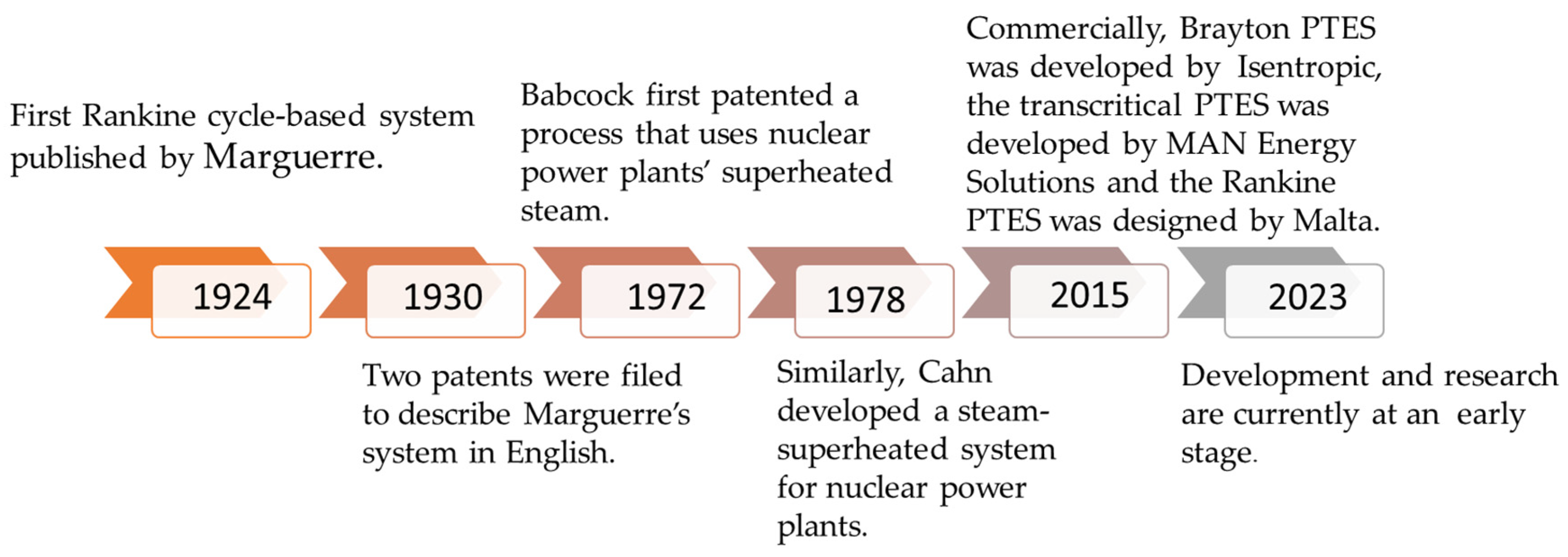
2. PTES Historical Background

The concept of storing energy with a heat pump and the engine has been developed for several generations since Marguerre first introduced a system consisting of two Thermal Energy Storage Systems (TESs) filled with wet steam in 1924 [14]. Two patents were filed in the 1930s that described Marguerre’s system in English [15].
In 1972, Babcock [16] first patented a process that uses nuclear power plants’ superheated steam. At 450 °C and 200 bars, a ceramic refractory accumulator was employed to compress and store the steam. A second early heat pump system was described in 1977 by Smith [17]. In the process of charging, the air is compressed, cooled, and then liquefied. Regenerators or packed beds are used to store the energy extracted during cooling, while tanks are used to store the liquefied air produced by the process. An open supercritical system is discharged by the Rankine cycle; compressed liquid air is reheated in a regenerator and then expanded to produce work through a turbine. During the charging process, the cool air obtained from the process is stored in the cool store and used for the liquefaction process. Similar to Babcock’s approach, a system was developed by Cahn [16] in 1978. Cahn proposed an energy system that could use thermal waste and would be independent of a power plant. In contrast to solid stores such as Babcock’s, the Cahn design does not have thermal fronts (a naturally unsteady phenomenon that reduces the maximum capacity utilisation of the tanks, and enhances self-discharge losses during storage, making the operation of the system relatively complex) and does not experience conductive losses.
The Highview Power system was developed between 2011 and 2014 and was a precursor to the LAES [18], as described by Morgan et al. [19]. However, there are some differences between these systems including: (i) compression–expansion processes (adiabatic or isothermal); (ii) liquefication processes (Claude cycle or Linde cycle); (iii) the number of compression and expansion phases; as well as the manner in which energy is recuperated. According to [20], Highview Power’s prototype was only 8% efficient; this value is low due to the small size of the plant and the ineffective use of the regenerator.
Park et al. [21] stated that the Highview design was constrained by pinch points that restricted the RTE (round-trip efficiency) to 36%. It is expected that further enhancements of the system will result in efficiency levels that exceed 50%. Accordingly, LAES may be able to achieve similar efficiencies to other PTES systems and also have the advantages of using proven technologies, geographical flexibility, and abundant storage media [21].
Joule–Brayton cycles and Rankine cycles have been used in recent studies to develop PTES systems. As part of the ISENTROPIC project, construction of a prototype based on a Joule–Brayton cycle began in 2015, while ABB is interested in building a prototype based on a Rankine cycle [21]. In the commercial sector, a number of PTES solutions exist or are being developed. These include the Brayton PTES developed by Isentropic [15], the transcritical PTES developed by MAN Energy Solutions [22] and the Rankine PTES designed by Malta. While development and research are currently at an early stage, some controversial results regarding key performance indicators, such as round-trip efficiency, have been reported. There has been no systematic investigation of how thermal energy storage impacts system performance; studies are urgently needed to maximise the potential of PTES [23]. The PTES development timeline is illustrated in Figure 2.

3. PTES Thermodynamic Cycles

The PTES systems can be broadly categorized into three groups based on the type of cycle they incorporate. Within each category, several variations have been proposed, including Joule–Brayton cycles, Rankine cycles, and transcritical cycles. In this section, the major systems within each category are reviewed, along with a brief comparison of each system. Figure 3 demonstrates the difference between the three types of PTES thermodynamic cycles.

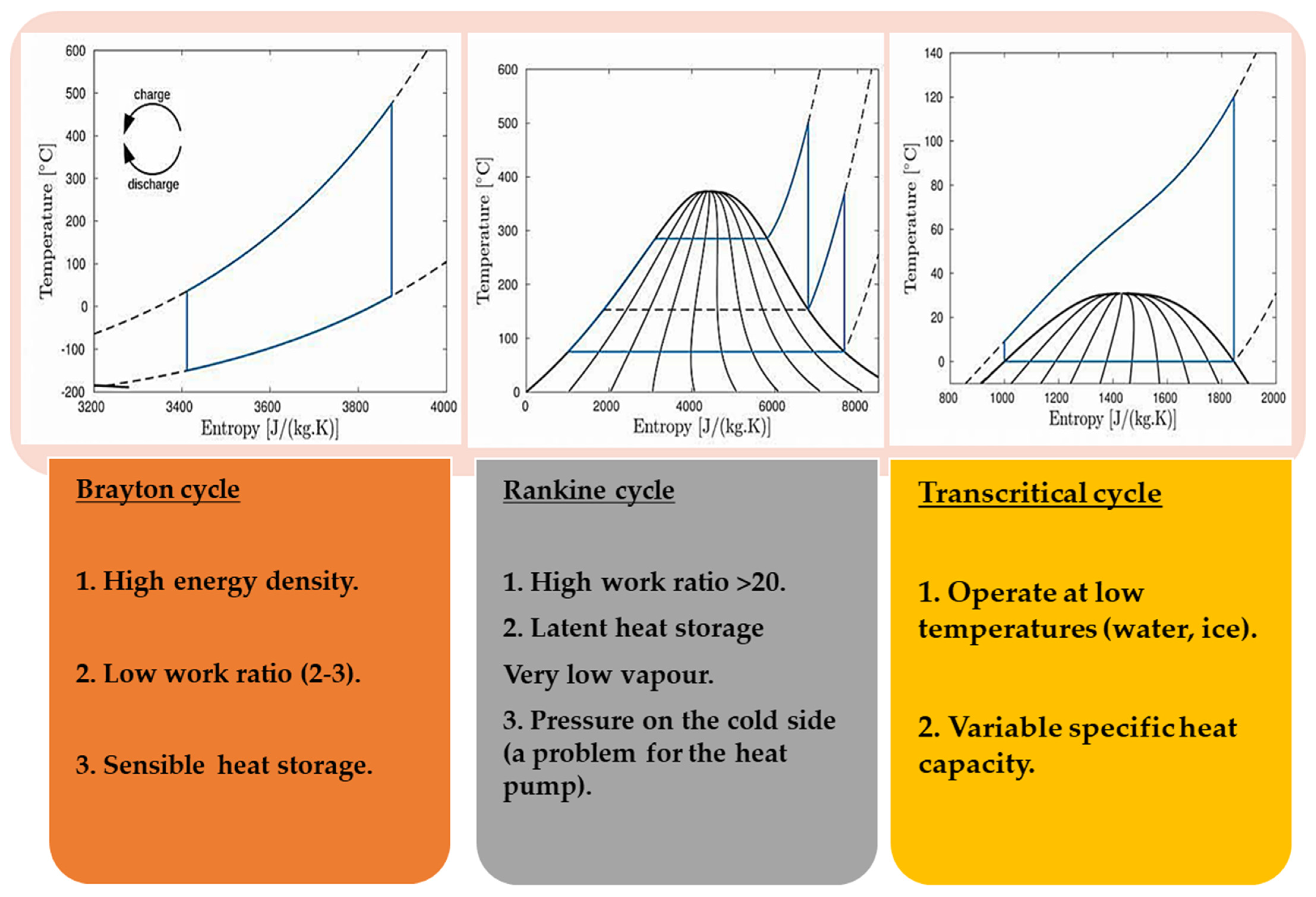
3.1. Joule–Brayton PTES Thermodynamic Cycle

Brayton heat pumps and heat engines are used in the Joule–Brayton PTES thermodynamic cycle. Brayton PTES is typically comprised of two thermal storage tanks, two expanders, and two compressors. In the standard configuration, both heat pumps and heat engines have a single compressor and expander. Reversible machines have also been proposed as a means of reducing costs for Brayton PTES; however, they produce lower performance. Volumetric [24] and dynamic [23] machines are both used in the Brayton PTES. The adoption of a reversible configuration is more accessible by using volumetric machines. The Brayton cycle requires sensible heat storage to overcome the temperature glide experienced during gas cooling and heating. There are two main configurations [23]: a packed-bed regenerator was proposed by Howes [15]; whereas, Laughlin [25] suggested a two-tank liquid storage system.
Packed beds refer to reservoirs full of solid materials (e.g., rocks) into which the fluid of the Brayton cycle flows directly. The most common arrangement is axial fluid flow; however, it has been proven that radial flow is more efficient and capable than axial flow [26]. A number of researchers deal with the selection of packing-bed materials, and Al2O3 and Fe2O3 have been recommended as the most suitable, owing to their excellent heat capacity–conductivity ratios [24,27,28]. Additionally, common rocks, such as basalt, which have lower costs, have been considered [29]. Based on a comprehensive study on packed-bed materials for a constant reservoir dimension, the researchers have determined that a variety of packing materials are capable of producing similar round-trip efficiencies, while storage capacity and charging/discharging periods differ [28]. The specific heat capacity of constant pressure, Cp, thermal conductivity, λ, and working temperature ranges of common solid sensible storage materials used in packed-bed systems are listed in Table 1 [30,31].
The packed-bed system is an economical and efficient means of storing thermal energy. However, it might be challenging to control and predict its behaviour, which makes it difficult to estimate the charge level.
Many authors [26,29,32] examined packed-bed dynamics analysis in order to determine Joule–Brayton PTES’s round-trip efficiency, output power, and energy density. Several research studies and projects [29,33,34] have indicated that to achieve cyclic operation (cyclic operation involves charging and discharging the store repeatedly until a steady-state periodic operation has been achieved) packed beds may require as many as 10 charges and discharges. Materials used for storage are capable of withstanding temperatures up to 1000 °C based on their composition [33].
Alternatively, Brayton PTES [34] may be equipped with two tanks for liquid storage. Generally, when high-temperature applications are required (300 to 500 °C), molten salts—usually made from NaNO3 and KNO3—are commonly used, whereas when low temperatures are required (60 to 100 °C), alcohols or hydrocarbons are frequently used [10,34]. Figure 4 considers the advantages and disadvantages of solid and liquid storage. The main properties of common liquid sensible storage materials used in packed-bed systems are listed in Table 1 [30,31].
The state of charge can be easily estimated with liquid-sensing thermal storage, making it easier to predict the system’s performance. A heat exchanger is necessary, and direct contact between the Brayton cycle liquid and the storage media is not recommended in practice. A heat exchanger of this type may have an extensive area for heat transfer, maximising round-trip efficiency, and reducing energy losses, but it may also be associated with an increase in investment costs [7,10].
The most common working fluids for the Brayton cycle are argon [33], helium [10], and air [28]. Given their higher temperatures at the same operating pressures, due to the higher specific heat ratio [35], the use of helium and argon is preferable to the use of air, and round-trip efficiency is determined by temperature ratios rather than pressure ratios [32]. The compression/expansion ratio of Brayton PTES usually ranges between two and four [25,33], although it can be higher [36].
Brayton PTES simulations indicate that round-trip efficiency is around 60% for both liquid sensible heat storage tanks and systems with packed beds when the machines have a polytropical efficient of at least 0.9. Additionally, round-trip efficiency is highly dependent on the performance of the machinery, such that if lower figures are used, round-trip efficiency can be found to be around 30% [7,28]. High-quality air turbomachines can currently achieve the polytropic efficiency of 0.9, but Brayton PTES uses different fluids, which may result in different round-trip efficiency values than have been reported [10].
Brayton PTES only has one pilot plant implemented (150 kW/600 kWh) to date. Research shows that Brayton PTES can be technically feasible, but it has a very low round-trip efficiency [29]. The estimated round-trip efficiency of a larger system (2 MW/16 MWh) ranges from 52% to 72%, based on a realistic theoretical estimate [6,37]. Based on the Brayton cycle, Guo et al. [38] initially developed a thermodynamic model based on PTES that neglected external heat losses and was based on a finite-rate heat transfer model. This model was further developed to include irreversible losses both internally and externally, on the basis of a weak dissipative assumption [39], and a more universal thermodynamic model has been developed.
Desrues et al. [33] considered a system based on the Brayton cycle, argon gas as the working fluid, for the development of PTES for a large-scale application. There is a possibility of reaching an RTE of 66.7%; however, a maximum temperature (1000 °C) is needed, which is higher than the existing compressor’s operating temperature of about 900 K. It is possible to partially resolve the constraint by adding a second electrical heater. Howes [15] studied the heat transfer processes and the losses of three PTES prototypes; reciprocating devices were used in place of compressor/turbine pairs. In addition, White et al. [40] examined the effects of storage tank geometry, operating mode, and temperatures on thermodynamic losses and indicated that long-term storage leads to significant losses, while periodic operation leads to acceptable losses.
Additionally, many authors have enhanced the arrangement of the system by studying the effects of a packed bed on the system, adding a buffer vessel, and investigating loss/generating mechanisms [24,26,32,41,42]. A transient analysis method for a (10 MW/4 h) PTES system was proposed by Wang et al. [29], who examined the impact of many factors, as well as comparing helium and argon-based systems. According to their findings, the RTE of helium is greater, and at the isentropic conditions and greater pressure ratios, the energy storage performance increases. The charging process involved the use of an electric heater in a plant designed by Benato et al. [27,28,43]. Moreover, a packed-bed (one-dimensional, two-phase) model is also developed, where two heat transfer fluids are tested along with nine heat storage materials.
Using air as the working fluid, Benato [27] developed a novel PTES based on the Brayton cycle power system. As part of the study, five types of high-storage materials were tested and investigated. Electric heaters are used in PTES systems to increase maximum storage temperature, so compressor pressure does not affect this parameter. There are two key factors determining why the proposed PTES could have a low RTE of approximately 10%: first, energy losses in the electric heater and second, losses associated with the process of removing the thermal front from the thermal storage tanks. McTigue et al. [24] examined the parameters that influence the PTES and presented optimised results. The thermodynamic analysis findings indicated that the efficiency of the compression and expansion processes was primarily responsible for the RTE of PTES. If the compressors and expanders could only achieve efficiencies that are typical of turbomachinery, the RTE would not exceed 50%.
An analytical model of a 10.5 MW, 5 h storage system based on packed-bed latent heat/cold storage was developed by Ge et al. [5]. The study also performed an energy and exergy analysis of the components. A study has also been conducted to determine whether packed-bed latent heat/cold stores could replace packed-bed sensible heat/cold stores for pumped thermal electricity storage. Systematic thermodynamic performance at optimal conditions was examined by examining the effects of porosities, compression ratios, inlet velocities, and isentropic efficiency. The study concluded that when latent heat and cold stores are replaced by packed-bed sensible heat and cold stores, the energy storage density of the system increases (from 232.5 to 245.4 kWh/m3). In addition, this system provides a round-trip efficiency of 84.7%, and a power density of 216.5 kW/m3, demonstrating competitiveness and efficiency over large-scale electrical energy storage systems [10].
A comparison between the solid storage materials and the liquid storage materials that are used in packed-bed systems and applications is presented in Figure 4.

3.2. Conventional Rankine Cycles

Heat engine expander and heat pump compressor components are used by Rankine PTES systems, and they are usually separated in standard configurations. Several studies have suggested that reversible configurations could be used in order to reduce investment costs [37,38,39,40,41,42,43,44].
As low temperatures (100 to 250 °C) typically used in Rankine PTES thermal storage systems, either latent heat storage or liquid sensible heat storage [39,45] or a combination of both are typically used. In general, the most used liquid sensible heat storage techniques are pressurised water and thermal oil [46]. To increase efficiency by avoiding mixing between storage tanks, it is possible to use two-tank liquid storage systems [47]. These are more costly and require doubling the storage.
Rankine cycle operating fluids must match the temperature profiles of the thermal exergy reservoirs properly in order to reduce the destruction of internal exergy. In this regard, a variety of thermal storage types have been proposed by researchers. For example, Morandin et al. [48,49] describe a multiple-tank liquid storage system to overcome the significant change in the specific heat of the working fluid in the supercritical region. In this arrangement, water is held in a number of tanks at incremental temperatures. During charge, the largest volume of water is in the hot tank, while during discharge, it is in the low-temperature tank. Similarly, Steinmann et al. [12] propose a hybrid latent and sensible thermal reservoir for recalibration of direct and inverse Rankine cycle condensing and evaporating temperatures. Although the complexity of this configuration may increase the system’s cost, it may also improve its performance, as well as necessitate the use of a more sophisticated control strategy [13].
In most Rankine PTES systems, the low-temperature reservoir is composed of a phase-change material. In most cases, the evaporation and condensation temperature profiles during charge and discharge are relatively flat; therefore, the best temperature profile matching is obtained by constant temperature storage. Cold latent storage is often proposed using water ice due to its low cost, high reliability, and long life span [39,45,48].
A high-temperature reservoir may also utilise phase-change materials. With subcritical Rankine cycles, latent heat storage ensures that condensation and evaporation temperature profiles (during charge and discharge, respectively) are precisely matched [12,50]. This can be achieved by utilising nitrate salts.
There are two types of Rankine PTES systems: transcritical cycles and subcritical cycles. Transcritical Rankine PTES commonly utilises CO2 as a working fluid [48,49], but other fluids including R1234ze(Z), R152A, and R1234ze(E) are also studied. By replacing CO2 with a different fluid, it can be used to achieve slightly higher performance at much lower operating pressures. The main difference between refrigerants and CO2 is that the operating pressure of the refrigerant is significantly lower, while the expansion and compression ratios are significantly higher, reaching 60 for R1234ze(Z). In order to achieve satisfactory efficiency, such machines may require more complex layouts, as several stages may be needed. Configurations with high compression and expansion ratios may be expensive.
A wide range of fluids, such as ammonia and water [50], as well as several organic refrigerants [47,51], have been examined for subcritical Rankine PTES. As nonorganic refrigerants possess comparatively larger specific works (i.e., enthalpy differences), they are more suited to larger systems. Compression is limited by a highly specific work, which means that several compression stages should be employed [50]. While organic fluids are expected to have lower efficiency, they might require simpler layouts. A carefully chosen organic refrigerant may require only a few compression stages during the charging phase, whereas a single-stage machine may be sufficient during the discharge phase.
Under realistic assumptions, Rankine PTES typically has a round-trip efficiency in the range of 50–60%. Steinmann [50] reported a 55–66% round-trip efficiency, Morandin et al. [48,49] suggested a value of up to 60%, and Koen et al. [46] found it to be between 50% and 55%. Comparison analyses conducted by Steinmann [52] indicate that the transcritical CO2 systems are less efficient than Brayton PTES systems. Although subcritical systems tend to be less efficient than transcritical systems, their layout is more straightforward and, therefore, more cost-effective.
Although the Rankine PTES is slightly less efficient than the Brayton PTES, it operates at a lower temperature, so it may pose fewer technical challenges. As a consequence of the low operating temperatures of the Rankine PTES, it has been proposed that low-temperature heat sources be integrated into the systems to improve system performance [47,51,53]. Solar thermal energy, waste heat, or geothermal energy are suitable for use [12,45]. As a result, the PTES may function as a bridge between different energy networks, or as a hybrid storage/waste heat recovery system (e.g., the district heating networks and the electric grid). There is a substantial impact on performance associated with additional thermal energy inputs. According to research, over 100% electrical round-trip efficiency may be achieved when thermal energy at 80 °C is exploited [51]. Therefore, thermal energy may contribute to a higher discharge of electrical power than was initially charged into the storage system.
The Organic Rankine Cycle (ORC) is a type of Rankine cycle that uses an organic working fluid; due to its high efficiency, simple structure, and environmental friendliness, the ORC is considered to be a promising technology for low-grade thermal energy recovery. ORC is considered to have improved the RTE of the PTES, because part of the waste heat is turned into electricity [9]. A standard ORC does not match both working fluid temperatures and heat transfer medium equally, which leads to significant energy loss during heat transfer. Due to irreversible heating, compression/expansion processes, heat exchangers can be used to remove heat from the working fluid, making them a suitable heat source for ORCs.
As with Brayton systems, the performance of Rankine PTES systems is greatly influenced by the isentropic and polytropic efficiency of the machine. To attain satisfactory results, high-quality machines are usually required (compressors with an isentropic efficiency greater than 0.8, while turbines have an isentropic efficiency equal to 0.9). A number of comparative studies have shown that Brayton systems are more sensitive to the performance of their machines than Rankine systems [52]. This is due to the back work ratio of the Brayton systems being much higher than the Rankine system and, for a given efficiency, the maximum round-trip efficiency decreases rapidly with an increase in the back work ratio [54].

3.3. The Transcritical Rankine Cycle

Researchers have extensively studied the transcritical Rankine cycle as a thermodynamic cycle for PTES. According to [52], the electrothermal energy storage (ETES) method employs transcritical CO2 cycles as thermodynamic cycles to store bulk electrical energy. There were two processes involved in this case: pumped heat was stored in hot water and cold energy was absorbed in cold water, which melted and became ice, respectively, as a result of the process. Similarly, Morandin [49] proposed a CO2 transcritical cycle which used hot water to store heat and cold energy in saltwater ice. Frate et al. [51] developed a new PTES solution that boosted the RTE of the system beyond 100% by utilising a low-grade heat source, which in this context is considered free heat. According to Wang et al. [55], the cold energy from LNG (liquefied natural gas) can enhance PTES RTE beyond 100% if used as a heat sink, as external heat sources may not always be accessible sinks.
However, the energy storage density of PTES that uses the transcritical Rankine cycle as the thermodynamic cycle is low (22 kWh/m3) [55]. A lower figure will be achieved if external heat sources are not taken into account. The Brayton cycle and packed-bed PTES were examined by Chen et al. [56] due to the higher storage density of energy (110–170 kWh/m3). An electric heater was used to improve the density of energy storage further.
It has been proposed that the significant energy loss during heat transfer [57] in an ORC can be overcome by utilising zeotropic mixtures [58], trilateral cycles [59], dual-loop ORCs [60], or transcritical ORCs [61]. Zeotropic ORCs have a higher efficiency than simple ORCs due to better matching between exchange curves. A lack of knowledge of fluid properties and an unknown heat coefficient will pose some difficulties in their practical implementation [62]. While the trilateral cycle is one of the most efficient heat recovery cycles for sensible heat resources, with the lack of effective two-phase expanders, its efficiency is severely limited [62]. It is more appropriate to use a dual-loop ORC in order to recover the waste heat associated with the multigrades, for instance, the heat generated from engine coolant and exhaust gases [60]. Another method of reducing thermal irreversibility in heat-transfer processes is a transcritical ORC [63]. Furthermore, if a recuperator is used and a small turbine is operated [64], the high temperature of the cycle allows us to achieve higher thermal efficiency than a standard ORC. An alternative method of reducing thermal irreversibility in heat transfer processes is transcritical ORC. With a recuperator and a small turbine, it is possible to improve thermal efficiency over that of a standard ORC [63,64].
Table 2 below summarises and compares the three technologies (Brayton, Rankine and transcritical cycles).

4. Analysis and Performance Enhancement of PTES

Recently, several PTES systems have been presented using a variety of thermodynamic cycles, including Joule–Brayton and Rankine [32]. Currently, a variety of plant configurations have been studied for Brayton-based PTES, comprehensive thermodynamic analyses have been undertaken, and performance has been evaluated under various operating conditions [9]. A study done by Guo et al. [65] examined the effects of the design solution on key performance indicators, such as cycle temperatures and pressure ratios, and identified an optimal design of a Brayton-based PTES configuration. In spite of this, McTigue et al. [24] concluded that round-trip efficiency is highly dependent on losses incurred during compression and expansion.
Exergy analysis conducted by Zhao et al. [66] indicated that the expander discharge caused the greatest amount of exergy loss. In addition, advanced exergy analysis indicated that cold heat exchangers during discharge account for a significant portion of avoidable exergy destruction (95%) among the system components studied. Wang et al. [29] analysed the PTES performance such as the effects of the heat transfer and the thermodynamics processes. A number of key factors in the design of TES systems, for example, aspect ratio and particle size, among others, are crucial for ensuring a stable discharging power and optimum round-trip efficiency. PTES performance has been investigated in this regard by Wang et al. [67], who examined TES arrangements based on the number and mode of reservoirs and operating modes. As a result of their findings, the operational modes significantly impact on the variation ratio of delivery power, and the round-trip efficiency of the system, while the tanks count has an insignificant influence. Previous studies have focused on sensible packed-bed heat storage systems using argon as the working fluid in the TES section. A number of other gases have also been studied, including helium, carbon dioxide, and air [28].
Dumont et al. [68] reported that academics frequently report round-trip efficiencies of approximately 60% to 70%; however, such levels of efficiency can only be conducted by extremely large polytropic efficiency rates of turbines and compressors, which are typically greater than 90%. Due to the fact that the Brayton-PTES system’s efficiency is greatly impacted by polytropic efficiency, assuming slightly lower polytropic efficiency would result in a significant reduction in round-trip efficiency. Therefore, various innovative solutions should be examined to enhance the competitiveness of such storage systems. A [15] suggestion was made to incorporate an electrical heater after the compressor, in order to convert electrical energy into thermal energy, which would enable the maximum cycle temperature to be independent of the pressure ratio of the compressor. The study demonstrated that despite a reduction in round-trip efficiency due to an electric heater, the cost of PTES could be reduced by reducing the heat exchange area and compressor size.
Zhang et al. [69] investigated the potential of a PTES system as a power and cooling/heating system. Based on their findings, active and appropriate heat delivery through the hot tank could significantly enhance the outlet’s temperature stability during the working fluid’s discharging phase, thereby improving the system’s power delivery stability and electrical efficiency. According to Dumont et al. [68], thermal integration can significantly reduce electricity losses when combined with other systems. Accordingly, Jockenhofer et al. [13] investigated the impact of adding additional heat sources to PTES systems in terms of enhancing the round-trip efficiency and the exergy efficiency of the system. According to Wang et al. [55], LNG cold energy may be able to be used as a heat sink for the PTES and a natural gas distribution system. The authors confirmed that thermal integration is feasible, as is the potential for enhancement of round-trip efficiency.
A Brayton cycle-based PTES system may also be suitable for integration into concentrated CSP. Solar energy can be captured and converted into electricity through a CSP system; however, solar radiation is intermittent, thus limiting the capacity factor. The integration of CSP plants with PTES systems may provide a solution to this limitation: Petrollese et al. [7] presented and evaluated a novel PTES system integrated with a CSP. As part of this system, the same working fluid (argon) is used as in the CSP, and several components can be operated simultaneously or independently. TES consists of three thermocline packed-bed tanks. During this study, the performance of a PTES-CSP plant integrated with TES tanks was modelled in MATLAB using specific mathematical models under nominal conditions. A study was conducted to investigate the impact of the key design parameters of TES systems (e.g., the operating temperatures and pressure ratio) on the key performance indicators. A pressure ratio of about 5:2 was found to be optimal for the integrated plant’s exergetic round-trip efficiency. From this, an efficient PTES-CSP system with an exergetic round-trip efficiency of approximately 60% has been developed [7].

5. Summary of Literature Review PTES

Recent research has focused on using PTES systems for power density applications. Table 3 and Table 4 summarise the various PTES systems described in the literature.

6. Conclusions

Different technologies have been presented and discussed in this paper. PTES systems are classified as high-temperature Brayton cycles and moderate-temperature Rankine cycles. The organic Rankine cycle features thermal integration using a low-temperature heat source, which results in considerable improvement in cycle efficiency. Nevertheless, thermal integration adds to the complexity of the system and results in a higher system cost. PTES systems such as transcritical CO2 Rankine cycles are also important to consider, as they deliver greater energy density and perform better than organic Rankine cycles. In addition, transcritical CO2 cycles provide a solution to the pinch problem associated with ORC by sensibly transferring heat to the secondary fluid in the supercritical region. By doing so, the cycle temperature profile is matched to the storage medium temperature profile, resulting in a higher work output from the system. Based on this, the lower operating temperatures are also beneficial for heat losses and provide a varied option for storage materials and secondary working fluids.
As a promising technology, Pumped Thermal Energy Storage (PTES) utilises a heat pump and a heat engine cycle to store electrical energy as thermal energy during charging and discharging. The PTES technology can be a valuable resource for storing large amounts of energy efficiently and economically, particularly when combined with Sensible Heat Thermal Energy Storage (SHTES). Although its efficiency is lower than that of commercial large-scale energy storage technologies, recent research has led to the development of this technology as a promising novel alternative to PHES and CAES. It also has the added advantage of being environmentally friendly and geographically unrestricted. Several studies have been conducted to optimise the round-trip process’s efficiency by analysing the power cycles, thermal storage systems, working fluids, operating conditions, and thermal integrations. Key features of the technology are below.
  • According to the latest research and studies, Pumped Thermal Energy Storage (PTES) could achieve round-trip efficiency of 60–65% for a system capable of storing 600 kWh of electricity.
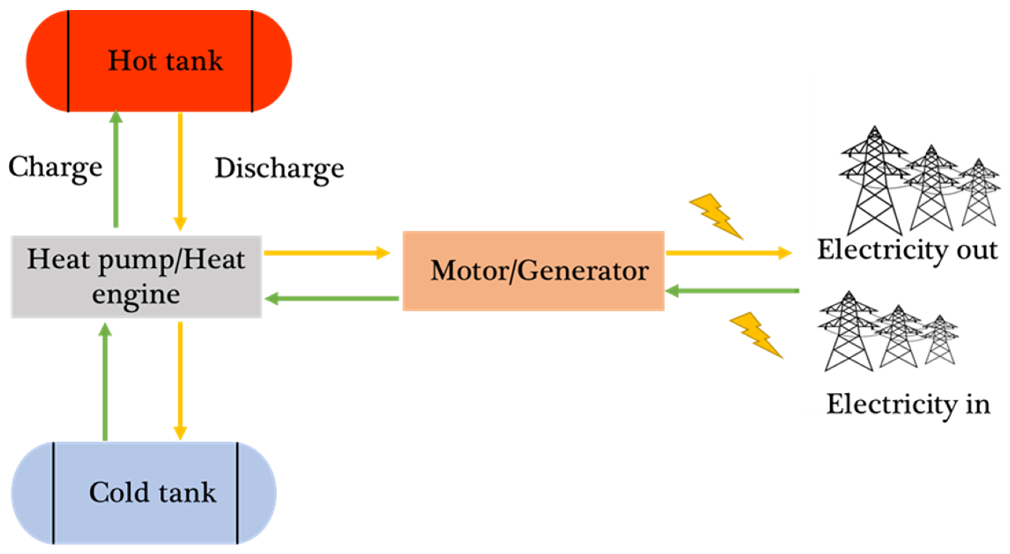
  • PTES uses a theoretically reversible thermodynamic cycle involving compression and expansion stages with constant pressure heat addition and rejection to hot and cold thermal stores.
  • Energy storage round-trip efficiency largely depends on the isentropic efficiencies of the compression and expansion equipment, the thermal effectiveness of the thermal stores, the presence of circuit pressure drops, heat leaks to and from the system, and electrical machine efficiencies.
  • PTES could offer a viable large-scale, long-duration energy store.
  • The Rankine PTES system has never been built as a standard layout. Accordingly, it is imperative that research efforts be directed towards demonstrating the results derived from simulations.

Author Contributions

Conceptualization, J.R. and J.M.B.; methodology, A.M.R.; investigation, A.M.R.; writing—original draft preparation, A.M.R.; writing—review and editing, A.M.R., J.R., and J.M.B.; visualization, A.M.R.; supervision, J.R. and J.M.B.; project administration, J.R. and J.M.B. All authors have read and agreed to the published version of the manuscript.

Funding

This research received no external funding.

Data Availability Statement

Not applicable.

Conflicts of Interest

The authors declare no conflict of interest.

References

  1. International Energy Agency. Global Energy Review 2021—Analysis—IEA. 2021. Available online: https://www.iea.org/reports/global-energy-review-2021/renewables (accessed on 11 May 2023).
  2. Rabi, A.M.; Radulovic, J.; Buick, J.M. Comprehensive Review of Compressed Air Energy Storage (CAES) Technologies. Thermo 2023, 3, 104–126. [Google Scholar] [CrossRef]
  3. Aneke, M.; Wang, M. Energy storage technologies and real life applications—A state of the art review. Appl. Energy 2016, 179, 350–377. [Google Scholar] [CrossRef] [Green Version]
  4. Borri, E.; Tafone, A.; Romagnoli, A.; Comodi, G. A review on liquid air energy storage: History, state of the art and recent developments. Renew. Sustain. Energy Rev. 2021, 137, 110572. [Google Scholar] [CrossRef]
  5. Ge, Y.; Zhao, Y.; Zhao, C. Transient simulation and thermodynamic analysis of pumped thermal electricity storage based on packed-bed latent heat/cold stores. Renew. Energy 2021, 174, 939–951. [Google Scholar] [CrossRef]
  6. Gallo, A.B.; Simõões-Moreira, J.R.; Costa, H.K.M.; Santos, M.M.; Moutinho dos Santos, E.M. Energy storage in the energy transition context: A technology review. Renew. Sustain. Energy Rev. 2016, 65, 800–822. [Google Scholar] [CrossRef]
  7. Petrollese, M.; Cascetta, M.; Tola, V.; Cocco, D.; Cau, G. Pumped thermal energy storage systems integrated with a concentrating solar power section: Conceptual design and performance evaluation. Energy 2022, 247, 123516. [Google Scholar] [CrossRef]
  8. Mazzucco, G.; Xotta, G.; Salomoni, V.; Giannuzzi, M.; Maiorana, C. Solid thermal storage with PCM materials. Numerical investigations. Appl. Therm. Eng. 2017, 124, 545–559. [Google Scholar] [CrossRef]
  9. Benato, A.; Stoppato, A. Pumped Thermal Electricity Storage: A technology overview. Therm. Sci. Eng. Prog. 2018, 6, 301–315. [Google Scholar] [CrossRef]
  10. Frate, G.F.; Ferrari, L.; Desideri, U. Energy storage for grid-scale applications: Technology review and economic feasibility analysis. Renew. Energy 2021, 163, 1754–1772. [Google Scholar] [CrossRef]
  11. Steinmann, W.D.; Jockenhöfer, H.; Bauer, D. Thermodynamic Analysis of High-Temperature Carnot Battery Concepts; Wiley-VCH Verlag GmbH & Co.: Stuttgart, Germany, 2020. [Google Scholar]
  12. Steinmann, W.-D.; Bauer, D.; Jockenhöfer, H.; Johnson, M. Pumped thermal energy storage (PTES) as smart sector-coupling technology for heat and electricity. Energy 2019, 183, 185–190. [Google Scholar] [CrossRef]
  13. Jockenhöfer, H.; Steinmann, W.-D.; Bauer, D. Detailed numerical investigation of a pumped thermal energy storage with low temperature heat integration. Energy 2018, 145, 665–676. [Google Scholar] [CrossRef]
  14. Fritz, M. Thermodynamic Energy Storage Method. U.S. Patent 1,979,393, 6 November 1934. [Google Scholar]
  15. Howes, J. Concept and Development of a Pumped Heat Electricity Storage Device. Proc. IEEE 2012, 100, 493–503. [Google Scholar] [CrossRef]
  16. Cahn, R.P.; Nicholson, E.W. Thermal Energy Storage by Means of Reversible Heat Pumping Utilizing Industrial Waste Heat. U.S. Patent 4,110,987, 5 September 1978. [Google Scholar]
  17. Smith, E.M. Storage of Electrical Energy Using Supercritical Liquid Air. Proc. Inst. Mech. Eng. 1977, 191, 289–298. [Google Scholar] [CrossRef]
  18. Chen, H.; Ding, Y.; Peters, T.; Berger, F. Method of Storing Energy and Cryogenic Energy Storage System. U.S. Patent 2016/0178129 A1, 23 June 2016. [Google Scholar]
  19. Morgan, R.; Nelmes, S.; Gibson, E.; Brett, G. Liquid air energy storage—Analysis and first results from a pilot scale demonstration plant. Appl. Energy 2014, 137, 845–853. [Google Scholar] [CrossRef]
  20. McTigue, J. Analysis & Optimization of Thermal Energy Storage. Doctoral Dissertation, Cambridge University Engineering Department, Cambridge, UK, 2016. [Google Scholar] [CrossRef]
  21. Park, J.-K.; Ro, P.I.; Lim, S.D.; Mazzoleni, A.P.; Quinlan, B. Analysis and Optimization of a Quasi-Isothermal Compression and Expansion Cycle for Ocean Compressed Air Energy Storage (OCAES). In Proceedings of the 2012 Oceans, Hampton Roads, VA, USA, 14–19 October 2012; pp. 1–8. [Google Scholar] [CrossRef]
  22. Meli, P. A Tale of Fire and Ice. MAN Energy Solutions. Available online: https://www.man-es.com/discover/a-tale-of-fire-and-ice (accessed on 3 May 2023).
  23. Albert, M.; Ma, Z.; Bao, H.; Roskilly, A.P. Operation and performance of Brayton Pumped Thermal Energy Storage with additional latent storage. Appl. Energy 2022, 312, 118700. [Google Scholar] [CrossRef]
  24. McTigue, J.D.; White, A.J.; Markides, C.N. Parametric studies and optimisation of pumped thermal electricity storage. Appl. Energy 2015, 137, 800–811. [Google Scholar] [CrossRef] [Green Version]
  25. Laughlin, R.B. Pumped thermal grid storage with heat exchange. J. Renew. Sustain. Energy 2017, 9, 044103. [Google Scholar] [CrossRef] [Green Version]
  26. McTigue, J.; White, A. A comparison of radial-flow and axial-flow packed beds for thermal energy storage. Appl. Energy 2018, 227, 533–541. [Google Scholar] [CrossRef]
  27. Benato, A. Performance and cost evaluation of an innovative Pumped Thermal Electricity Storage power system. Energy 2017, 138, 419–436. [Google Scholar] [CrossRef]
  28. Benato, A.; Stoppato, A. Heat transfer fluid and material selection for an innovative Pumped Thermal Electricity Storage system. Energy 2018, 147, 155–168. [Google Scholar] [CrossRef]
  29. Wang, L.; Lin, X.; Chai, L.; Peng, L.; Yu, D.; Chen, H. Cyclic transient behavior of the Joule–Brayton based pumped heat electricity storage: Modeling and analysis. Renew. Sustain. Energy Rev. 2019, 111, 523–534. [Google Scholar] [CrossRef]
  30. Zhao, Y.; Zhao, C.; Wen, T.; Markides, C.N. High Temperature Sensible Storage—Industrial Applications. Encycl. Energy Storage 2022, 1, 424–432. [Google Scholar] [CrossRef]
  31. Bauer, T.; Steinmann, W.-D.; Laing, D.; Tamme, R. Thermal energy storage materials and systems. Annu. Rev. Heat Transf. 2012, 15, 131–177. [Google Scholar] [CrossRef]
  32. White, A.; Parks, G.; Markides, C.N. Thermodynamic analysis of pumped thermal electricity storage. Appl. Therm. Eng. 2013, 53, 291–298. [Google Scholar] [CrossRef] [Green Version]
  33. Desrues, T.; Ruer, J.; Marty, P.; Fourmigué, J.F. A thermal energy storage process for large scale electric applications. Appl. Therm. Eng. 2010, 30, 425–432. [Google Scholar] [CrossRef] [Green Version]
  34. McTigue, J.D.; Markides, C.N.; White, A.J. Performance response of packed-bed thermal storage to cycle duration perturbations. J. Energy Storage 2018, 19, 379–392. [Google Scholar] [CrossRef]
  35. Kim, Y.-M.; Shin, D.-G.; Lee, S.-Y.; Favrat, D. Isothermal transcritical CO2 cycles with TES (thermal energy storage) for electricity storage. Energy 2013, 49, 484–501. [Google Scholar] [CrossRef]
  36. Davenne, T.R.; Peters, B.M. An Analysis of Pumped Thermal Energy Storage With De-coupled Thermal Stores. Front. Energy Res. 2020, 8, 160. [Google Scholar] [CrossRef]
  37. Dumont, O.; Lemort, V. Mapping of performance of pumped thermal energy storage (Carnot battery) using waste heat recovery. Energy 2020, 211, 118963. [Google Scholar] [CrossRef]
  38. Guo, J.; Cai, L.; Chen, J.; Zhou, Y. Performance optimization and comparison of pumped thermal and pumped cryogenic electricity storage systems. Energy 2016, 106, 260–269. [Google Scholar] [CrossRef]
  39. Mercangöz, M.; Hemrle, J.; Kaufmann, L.; Z’graggen, A.; Ohler, C. Electrothermal energy storage with transcritical CO2 cycles. Energy 2012, 45, 407–415. [Google Scholar] [CrossRef]
  40. White, A.J. Loss analysis of thermal reservoirs for electrical energy storage schemes. Appl. Energy 2011, 88, 4150–4159. [Google Scholar] [CrossRef] [Green Version]
  41. White, A.; McTigue, J.; Markides, C. Wave propagation and thermodynamic losses in packed-bed thermal reservoirs for energy storage. Appl. Energy 2014, 130, 648–657. [Google Scholar] [CrossRef] [Green Version]
  42. White, A.J.; McTigue, J.; Markides, C. Analysis and optimisation of packed-bed thermal reservoirs for electricity storage applications. Proc. Inst. Mech. Eng. Part A J. Power Energy 2016, 230, 739–754. [Google Scholar] [CrossRef]
  43. Benato, A.; Stoppato, A.; Mirandola, A. State-of-the-art and future development of sensible heat thermal electricity storage systems. Int. J. Heat Technol. 2017, 35, S244–S251. [Google Scholar] [CrossRef]
  44. Staub, S.; Bazan, P.; Braimakis, K.; Müller, D.; Regensburger, C.; Scharrer, D.; Schmitt, B.; Steger, D.; German, R.; Karellas, S.; et al. Reversible Heat Pump–Organic Rankine Cycle Systems for the Storage of Renewable Electricity. Energies 2018, 11, 1352. [Google Scholar] [CrossRef] [Green Version]
  45. Henchoz, S.; Buchter, F.; Favrat, D.; Morandin, M.; Mercangöz, M. Thermoeconomic analysis of a solar enhanced energy storage concept based on thermodynamic cycles. Energy 2012, 45, 358–365. [Google Scholar] [CrossRef]
  46. Koen, A.; Antunez, P.F.; White, A. A Study of Working Fluids for Transcritical Pumped Thermal Energy Storage Cycles. In Proceedings of the 2019 Offshore Energy and Storage Summit (OSES), Brest, France, 10–12 July 2019; pp. 1–7. [Google Scholar] [CrossRef]
  47. Frate, G.F.; Ferrari, L.; Desideri, U. Multi-criteria investigation of a pumped thermal electricity storage (PTES) system with thermal integration and sensible heat storage. Energy Convers. Manag. 2020, 208, 112530. [Google Scholar] [CrossRef]
  48. Morandin, M.; Maréchal, F.; Mercangöz, M.; Buchter, F. Conceptual design of a thermo-electrical energy storage system based on heat integration of thermodynamic cycles—Part B: Alternative system configurations. Energy 2012, 45, 386–396. [Google Scholar] [CrossRef]
  49. Morandin, M.; Maréchal, F.; Mercangöz, M.; Buchter, F. Conceptual design of a thermo-electrical energy storage system based on heat integration of thermodynamic cycles—Part A: Methodology and base case. Energy 2012, 45, 375–385. [Google Scholar] [CrossRef]
  50. Steinmann, W. The CHEST (Compressed Heat Energy STorage) concept for facility scale thermo mechanical energy storage. Energy 2014, 69, 543–552. [Google Scholar] [CrossRef]
  51. Frate, G.F.; Antonelli, M.; Desideri, U. A novel Pumped Thermal Electricity Storage (PTES) system with thermal integration. Appl. Therm. Eng. 2017, 121, 1051–1058. [Google Scholar] [CrossRef]
  52. Steinmann, W.-D.; Jockenhöfer, H.; Bauer, D. Thermodynamic Analysis of High-Temperature Carnot Battery Concepts. Energy Technol. 2020, 8, 1900895. [Google Scholar] [CrossRef] [Green Version]
  53. Frate, G.F.; Antonelli, M.; Desideri, U. Pumped Thermal Electricity Storage: An Interesting Technology for Power-to-Heat Applications. 2018. Available online: https://arpi.unipi.it/handle/11568/924310 (accessed on 5 December 2022).
  54. Ayachi, F.; Tauveron, N.; Tartière, T.; Colasson, S.; Nguyen, D. Thermo-Electric Energy Storage involving CO2 transcritical cycles and ground heat storage. Appl. Therm. Eng. 2016, 108, 1418–1428. [Google Scholar] [CrossRef]
  55. Wang, G.-B.; Zhang, X.-R. Thermodynamic analysis of a novel pumped thermal energy storage system utilizing ambient thermal energy and LNG cold energy. Energy Convers. Manag. 2017, 148, 1248–1264. [Google Scholar] [CrossRef]
  56. Chen, L.X.; Hu, P.; Zhao, P.P.; Na Xie, M.; Wang, F.X. Thermodynamic analysis of a High Temperature Pumped Thermal Electricity Storage (HT-PTES) integrated with a parallel organic Rankine cycle (ORC). Energy Convers. Manag. 2018, 177, 150–160. [Google Scholar] [CrossRef]
  57. Nemati, A.; Nami, H.; Yari, M. Assessment of different configurations of solar energy driven organic flash cycles (OFCs) via exergy and exergoeconomic methodologies. Renew. Energy 2018, 115, 1231–1248. [Google Scholar] [CrossRef]
  58. Liu, Q.; Shen, A.; Duan, Y. Parametric optimization and performance analyses of geothermal organic Rankine cycles using R600a/R601a mixtures as working fluids. Appl. Energy 2015, 148, 410–420. [Google Scholar] [CrossRef]
  59. Fischer, J. Comparison of trilateral cycles and organic Rankine cycles. Energy 2011, 36, 6208–6219. [Google Scholar] [CrossRef]
  60. Shu, G.; Yu, Z.; Liu, P.; Xu, Z.; Sun, R. Potential of a thermofluidic feed pump on performance improvement of the dual-loop Rankine cycle using for engine waste heat recovery. Energy Convers. Manag. 2018, 171, 1150–1162. [Google Scholar] [CrossRef]
  61. Dong, B.; Xu, G.; Luo, X.; Zhuang, L.; Quan, Y. Analysis of the supercritical organic Rankine cycle and the radial turbine design for high temperature applications. Appl. Therm. Eng. 2017, 123, 1523–1530. [Google Scholar] [CrossRef]
  62. Baccioli, A.; Antonelli, M. Organic Flash Cycles: Off-design behavior and control strategies of two different cycle architectures for Waste Heat Recovery applications. Energy Convers. Manag. 2018, 157, 176–185. [Google Scholar] [CrossRef]
  63. Pan, L.; Wang, H.; Shi, W. Performance analysis in near-critical conditions of organic Rankine cycle. Energy 2012, 37, 281–286. [Google Scholar] [CrossRef]
  64. Gao, H.; Liu, C.; He, C.; Xu, X.; Wu, S.; Li, Y. Performance Analysis and Working Fluid Selection of a Supercritical Organic Rankine Cycle for Low Grade Waste Heat Recovery. Energies 2012, 5, 3233–3247. [Google Scholar] [CrossRef] [Green Version]
  65. Guo, J.; Cai, L.; Chen, J.; Zhou, Y. Performance evaluation and parametric choice criteria of a Brayton pumped thermal electricity storage system. Energy 2016, 113, 693–701. [Google Scholar] [CrossRef]
  66. Zhao, Y.; Liu, M.; Song, J.; Wang, C.; Yan, J.; Markides, C.N. Advanced exergy analysis of a Joule-Brayton pumped thermal electricity storage system with liquid-phase storage. Energy Convers. Manag. 2021, 231, 113867. [Google Scholar] [CrossRef]
  67. Wang, L.; Lin, X.; Zhang, H.; Peng, L.; Chen, H. Brayton-cycle-based pumped heat electricity storage with innovative operation mode of thermal energy storage array. Appl. Energy 2021, 291, 116821. [Google Scholar] [CrossRef]
  68. Dumont, O.; Frate, G.F.; Pillai, A.; Lecompte, S.; De Paepe, M.; Lemort, V. Carnot battery technology: A state-of-the-art review. J. Energy Storage 2020, 32, 101756. [Google Scholar] [CrossRef]
  69. Zhang, H.; Wang, L.; Lin, X.; Chen, H. Combined cooling, heating, and power generation performance of pumped thermal electricity storage system based on Brayton cycle. Appl. Energy 2020, 278, 115607. [Google Scholar] [CrossRef]
  70. Zhao, Y.; Song, J.; Liu, M.; Zhao, Y.; Olympios, A.V.; Sapin, P.; Yan, J.; Markides, C.N. Thermo-economic assessments of pumped-thermal electricity storage systems employing sensible heat storage materials. Renew. Energy 2022, 186, 431–456. [Google Scholar] [CrossRef]
  71. Farres Antunez, P. Modelling of Thermal Energy Storage Systems for Bulk Electricity Storage, Doctoral Report; Cambridge University: Cambridge, UK, 2015. [CrossRef]
  72. Ni, F.; Caram, H.S. Analysis of pumped heat electricity storage process using exponential matrix solutions. Appl. Therm. Eng. 2015, 84, 34–44. [Google Scholar] [CrossRef]
  73. Smallbone, A. Carnot Battery Energy Storage: A More Cost-Effective and Flexible Solution for Grid-Scale Energy Storage. 2019. Available online: https://www.rushlightevents.com/wp-content/uploads/2019/02/RUSHLIGHT-SHOW-2019-CLEANTECH-CONF-PANEL-1-NEWCASTLE-UNIV.pdf (accessed on 16 December 2022).
  74. Georgiou, S.; Aunedi, M.; Strbac, G.; Markides, C.N. Application of Liquid-Air and Pumped-Thermal Electricity Storage Systems in Low-Carbon Electricity Systems. In Proceedings of the Heat Powered Cycles (HPC-2018), Bayreuth, Germany, 16–19 September 2018. [Google Scholar]
  75. Georgiou, S.; Shah, N.; Markides, C.N. A thermo-economic analysis and comparison of pumped-thermal and liquid-air electricity storage systems. Appl. Energy 2018, 226, 1119–1133. [Google Scholar] [CrossRef]
  76. Georgiou, S.; Aunedi, M.; Strbac, G.; Markides, C.N. On the value of liquid-air and pumped-thermal electricity storage systems in low-carbon electricity systems. Energy 2020, 193, 116680. [Google Scholar] [CrossRef]
  77. Wang, L.; Lin, X.; Chai, L.; Peng, L.; Yu, D.; Liu, J.; Chen, H. Unbalanced mass flow rate of packed bed thermal energy storage and its influence on the Joule-Brayton based Pumped Thermal Electricity Storage. Energy Convers. Manag. 2019, 185, 593–602. [Google Scholar] [CrossRef]
  78. Dietrich, A.; Dammel, F.; Stephan, P. Exergoeconomic analysis of a pumped heat electricity storage system based on a Joule/Brayton cycle. Energy Sci. Eng. 2021, 9, 645–660. [Google Scholar] [CrossRef]
  79. Ceran, B. A comparative analysis of energy storage technologies. Polityka Energetyczna Energy Policy J. 2018, 21, 97–110. [Google Scholar] [CrossRef]
  80. Farres-Antunez, P.; McTigue, J.D.; White, A.J. A Pumped Thermal Energy Storage Cycle with Capacity for Concentrated Solar Power Integration. In Proceedings of the 2019 Offshore Energy and Storage Summit, OSES, Brest, France, 10–12 July 2019. [Google Scholar] [CrossRef]
  81. White, A.J. High-Performance Heat Exchangers for Thermo-Mechanical Energy Storage; University of Cambridge: Cambridge, UK, 2020. [Google Scholar] [CrossRef]
  82. Farres-Antunez, P. Modelling and Development of Thermo-Mechanical Energy Storage. Ph.D. Thesis, The University of Cambridge, Cambridge, UK, 2018. [Google Scholar]
  83. Farres-Antunez, P.; White, A.J.J. Thermodynamic Strategies for Pumped Thermal Exergy Storage (PTES) with Liquid Reservoirs. In Proceedings of the UK Energy Storage Conference, Birmingham, UK, 30 November–2 December 2016; pp. 1–45. [Google Scholar] [CrossRef]
  84. Xue, H. A comparative study of the Adiabatic Compressed Air Energy Storage (A-CAES) and Pumped Thermal Energy Storage (PTES) systems. In Proceedings of the 2019 Offshore Energy and Storage Summit, OSES, Brest, France, 10–12 July 2019. [Google Scholar] [CrossRef]
  85. Salomone-González, D.; González-Ayala, J.; Medina, A.; Roco, J.; Curto-Risso, P.; Hernández, A.C. Pumped heat energy storage with liquid media: Thermodynamic assessment by a Brayton-like model. Energy Convers. Manag. 2020, 226, 113540. [Google Scholar] [CrossRef]
  86. McTigue, J.; Farres-Antunez, P.; Ellingwood, K.; Neises, T.; White, A. Pumped Thermal Electricity Storage with Supercritical CO2 Cycles and Solar Heat Input; National Renewable Energy Laboratory: Golden, CO, USA, 2019; NREL/CP-5500-74753. Available online: https://www.nrel.gov/docs/fy20osti/74753.pdf (accessed on 5 July 2023).
  87. Morandin, M.; Mercangöz, M.; Hemrle, J.; Maréchal, F.; Favrat, D. Thermoeconomic design optimization of a thermo-electric energy storage system based on transcritical CO2 cycles. Energy 2013, 58, 571–587. [Google Scholar] [CrossRef]
  88. Baik, Y.-J.; Heo, J.; Koo, J.; Kim, M. The effect of storage temperature on the performance of a thermo-electric energy storage using a transcritical CO2 cycle. Energy 2014, 75, 204–215. [Google Scholar] [CrossRef]
  89. Tauveron, N.; Macchi, E.; Nguyen, D.; Tartière, T. Experimental Study of Supercritical CO2 Heat Transfer in a Thermo-Electric Energy Storage Based on Rankine and Heat-Pump Cycles. Energy Procedia 2017, 129, 939–946. [Google Scholar] [CrossRef]
  90. Abarr, M.L. Modeling Pumped Thermal Energy Storage with Waste Heat Harvesting. 2016. Available online: https://scholar.colorado.edu/mcen_gradetdshttps://scholar.colorado.edu/mcen_gradetds/124 (accessed on 10 July 2023).
  91. Abarr, M.; Hertzberg, J.; Montoya, L.D. Pumped Thermal Energy Storage and Bottoming System Part B: Sensitivity analysis and baseline performance. Energy 2017, 119, 601–611. [Google Scholar] [CrossRef]
  92. Abarr, M.; Geels, B.; Hertzberg, J.; Montoya, L.D. Pumped thermal energy storage and bottoming system part A: Concept and model. Energy 2017, 120, 320–331. [Google Scholar] [CrossRef]
Figure 1. PTES standard layout and main components, charging and discharging cycle.
Thermo 03 00024 g001
Figure 2. PTES historical timeline.
Thermo 03 00024 g002
Figure 3. Comparison between the common PTES thermodynamic cycles.
Thermo 03 00024 g003
Figure 4. Main advantages and disadvantages of solid and liquid storage.
Thermo 03 00024 g004
Table 1. High-temperature solid and liquid sensible heat storage properties of commonly used materials, adapted from [30,31].
MaterialsType(Cp) [kJ/kg·K]λ [W/(m·K)]Working Temperature [°C]
Silica fire bricksSolid11.5200–700
Reinforced concreteSolid0.851.5200–400
Cast ironSolid0.5637200–400
BasaltSolid1.2311.5~500
Fe2O3Solid0.8514.91~600
Al2O3Solid1.16711.1~700–800
Carbonate saltsLiquid1.82450–850
Nitrate saltsLiquid1.60.52256–565
Liquid sodiumLiquid1.371270–530
Nitrite saltsLiquid1.50.57250–450
Silicone oilLiquid2.10.1300–400
Mineral oilLiquid2.60.12200–300
Table 2. A comparison between the three PTES’s thermodynamic cycles (transcritical, Brayton and Rankine).
PTES CycleWorking FluidOperating TemperaturesAdvantagesDisadvantages
Brayton cycleAir/Argon are commonly usedHot storage: (500–1000) °C
Cold storage: as low as −70 °C
  • It is highly efficient at any temperature limit and pressure ratio.
  • Energy and power density are increased with a higher temperature ratio.
  • There is less friction loss in fluids.
  • Low emission.
  • The round-trip efficiency is highly dependent on turbomachinary efficiency.
  • Using low-grade heat integration to support PTES is also difficult due to the high temperature requirements.
  • High cost associated with high requirements and design.
  • A large air heater is required.
Rankine cycleThermal oil/pressurised water are commonly usedOperate at low temperature (100–250) °C
  • Widely available and cheap.
  • Low friction losses (low viscosity).
  • Less material requirements (chemical stable).
  • High heat capacity (excellent medium for heat transfer).
  • Heat pump cycles with lower cycle temperatures reduce thermal losses and maximise efficiency by incorporating low-grade waste heat with the classical cycle.
  • Big insulation needed (turbine, condenser), high specific volume and very low pressure due to low condensation temperature.
  • Efficiency loss and limited suitability to waste heat recovery
  • Expensive multistage turbine needed.
Transcritical cycleCO2Around 31 °C
  • Good match with heat source profile.
  • High exergy efficiency.
  • Environmentally friendly.
  • Inexpensive and nontoxic working fluid (CO2)
  • An expensive setup for improved cycles.
  • Several stages of expansion needed (large volume ratio).
Table 3. A summary of the Joule–Brayton cycle studies in the literature.
Efficiency [%]Heat Transfer Fluid Studied Thermal Energy Storage SystemRef.
Ƞstorage = 67 Ar Storage tanks (refractory bricks) [33]
ƞ RTE = 72 Ar Packed bed (granite) [15]
ƞ RTE = 70 Ar Packed bed (gravel) [20,32,40,70,71]
ƞ RTE = (64–82) Air/Ar Storage tanks (refractory materials) [72]
ƞ RTE = 40 Ideal gas __[65]
ƞ RTE = (52–72) Ar Packed bed [40,73]
__ Air/Ar Packed bed [27,28]
ƞ RTE = (42–50) Air/Ar Packed bed (alumina) [56]
ƞ RTE = 80 Ar Packed bed (magnetite) [36,74,75,76]
ƞ RTE = (39–57) He/Ar Packed bed (basalt) [29,69,77]
ƞ RTE = (45–57) Air/Ar Packed-bed storage tank and regenerator (molten salt) [52]
ƞ RTE = 43 Air [78,79]
__N2/Ar Storage tank (hexane, solar salt) [25],
ƞ RTE = (55–62) He/N2/Air Storage tank (thermal oil, molten salt, and pentane) [56,71,80,81,82,83]
ƞ RTE = (50–60) Air/Ar Storage tanks (solar salt, methanol, mineral oil, and propane) [79,84]
ƞ RTE = (35–40) Air/Ar Storage tank (solar salt, cryogenic liquids) [85]
Exergy efficiency (34–57) Ar Storage tank (butane, solar salt) [66]
ƞ RTE (60–78) CO2 Storage tanks (synthetic fluids and molten salt) [86]
Table 4. A summary of the transcritical Rankine cycle studies in the literature.
Efficiency [%]HTFThermal Energy StoreReference
ƞ RTE = 65 1;
ƞ RTE = 51 2
CO2Storage tanks (ice, hot water)[39]
ƞ RTE = (48–64)CO2Storage tanks (ice, hot water)[48,49,87]
ƞ RTE = (65–73)CO2Storage tanks (ice, hot water)[35]
ƞ RTE = 30CO2Storage tanks (water)[88]
ƞ RTE = (43–56)CO2Phase-change materials and grounded heat storage [54,89]
ƞ RTE = (52–66)CO2Hot thermal energy storage (tube-in-concrete)[89,90,91,92]
ƞ RTE = 139CO2/NH3 Heat exchanger and storage tanks[55]
ƞ RTE = 58R13I1 and CO2 Storage tanks (oils and water)[46]
1 Commercial plant; 2 Pilot plants.
Disclaimer/Publisher’s Note: The statements, opinions and data contained in all publications are solely those of the individual author(s) and contributor(s) and not of MDPI and/or the editor(s). MDPI and/or the editor(s) disclaim responsibility for any injury to people or property resulting from any ideas, methods, instructions or products referred to in the content.

