Article

Effective Cooling System for Solar Photovoltaic Cells Using NEPCM Impingement Jets

School of Engineering, Macquarie University, Sydney, NSW 2109, Australia
*
Author to whom correspondence should be addressed.
Thermo 2022, 2(4), 383-393; https://doi.org/10.3390/thermo2040026
Submission received: 21 September 2022 / Revised: 11 October 2022 / Accepted: 20 October 2022 / Published: 26 October 2022
(This article belongs to the Topic Cooling Technologies and Applications)

Abstract

:
Attention to photovoltaic (PV) cells to convert solar irradiation into electricity is significantly growing for domestic usage and large-scale projects such as solar farms. However, PV efficiency decreases on hot days. This paper proposes an effective cooling technique consisting of a 2% nano encapsulated phase change material (NEPCM) slurry and impinging jets (IJs) in a PV system. The impact of five influencing parameters on PV efficiency is studied using a multi-phase volume of fluid (VOF) model encompassing the effects of solar irradiation, latent heat, mass flow rate, number of nozzles, and jet-to-surface distance. The maximum efficiency of 15.82% is achieved under irradiation of 600 W/m2. The latent heat shows a slight improvement at the low particle concentration. Increasing the mass flow rate to 0.12 kg/s enhances the PV output power by 17.32%. While the PV performance is shown to be improved over the increment of the number of nozzles, the jet-to-surface spacing of 5.1 mm records a remarkable PV surface temperature reduction to 33.8 °C, which is the ideal operating temperature for the PV panel.

1. Introduction

Traditional fuels are the major contributor to releasing carbon dioxide into the air, causing adverse effects such as greenhouse gas and global warming [1,2]. The rapid depletion of fossil fuels has inspired extensive research to alter conventional energy resources with renewable energy alternatives. The sun provides renewable, sustainable, and cost-competitive energy. Photovoltaic (PV) cells are an excellent technique for converting solar energy to electricity. However, PV efficiency decreases under high temperatures, and manufacturers recommend to maintain the PV temperature at 25 °C to achieve the maximum output power [3]. Integrating an effective cooling system into solar PV panels provides a lower surface temperature and boosts PV performance [4].
Different cooling techniques have been studied for the PV panels [5,6,7], divided into passive and active categories [8]. It was shown that a cooling system increased PV efficiency by 38.4% [5]. Integrating PV panels with thermal collectors has been widely studied, since it can provide lower PV temperature, higher efficiency, and hot water for domestic usage [9,10,11,12]. According to previous studies [2,13], jet impingement provides higher heat transfer, controlling the surface temperature effectively. Bahaidarah [14] reported a temperature reduction of 33 °C using jet impingement cooling (JIC) in a PV module. In a comprehensive study [2], different configurations of water impingement jets (IJs) were analysed in a PV system. It was found that IJs with higher mass flow rates enhanced the output power by 47.67% at the small jet-to-surface distance.
The dispersion of nanoparticles into base fluids offers better performance in the JIC system [15]. In our previous study [16], we conducted a parametric study to find the optimum design of multiple IJs using nanofluids. It was demonstrated that the maximum output power increased by 20.36% compared to the conventional PV panel. Later, Javidan and Jabari Moghadam [17] carried out an experimental investigation on a JIC system using nanofluids. They showed that multiple orifice nozzles provided better performance than single orifice nozzles. Ag nanoparticles demonstrated better performance than alumina particles with 45% heat transfer enhancement in a PVT system [18]. Mustafa et al. [19] showed that nanofluids and lower solar irradiation resulted in higher efficiency. Using phase change materials (PCMs) in solar panels as a passive cooling technique results in lower surface temperature. Khodadadi and Sheikholeslami [4] conducted a study on the effect of integrating PCMs, fins, and nanofluids in a PVT system. They could enhance electrical and thermal efficiency by 13.25 and 79.54%, respectively. Nanofluids demonstrate higher thermal conductivity, while the risk of agglomeration and sedimentation is higher [15].
However, advanced nanotechnology offers nano encapsulated phase change material (NEPCM) to tackle existing deficiencies. A polymer shell around NEPCMs prevents particles from leakage and agglomeration [20]. Moreover, due to releasing latent heat, NEPCM slurries have a higher effective heat capacity than nanofluids [21]. Therefore, NEPCM is an excellent alternative for cooling systems [22,23,24,25]. Kuravi et al. [26] found that increasing the effective viscosity of NEPCM slurries caused a higher pressure drop. They also showed that slurries with the mass fractions of up to 30% can be assumed Newtonian. Later, Mohammadpour et al. [27] maximised the heat transfer coefficient enhancement to 28.5% in a microchannel at the NEPCM particle concentration of 0.2 while the figure of merit decreased. Influential parameters contributing to NEPCM heat transfer were reviewed by Salunkhe et al. [11]. Moreover, 67% heat transfer enhancement was reported by Lu et al. [14] using the NEPCM slurry.
To the best of the authors’ knowledge, a limited number of pertinent research computationally studied PV/JIC systems. In addition, the NEPCM slurry is the potential and recent alternative to use as a coolant instead of air, water, and nanofluids. The present research aims to find the effectiveness of multiple impinging jets using NEPCM slurry to maximise PV efficiency by controlling PV temperature. A computational study is conducted to examine the effects of influential parameters on PV efficiency. The investigating parameters included in this study are the effects of solar irradiation, latent heat, mass flow rate, number of nozzles, and jet-to-surface distance.

2. Physical and Mathematical Model

Problem Definition

Figure 1a shows the physical model of a PV/JIC system, which is similar to the experimental model of the ZT10-18-P PV panel [2]. The nominal operating cell temperature (NOCT) equals 45 ± 2 °C. Table 1 presents the design parameters and thermophysical properties of each component. The PV module dimensions are 350 × 270 × 17 mm. Figure 1b shows different nozzle arrays examined in the present study. Previous studies showed that although a reduction of the nozzle diameter from 2 to 1 mm improved the PV efficiency, it led to a higher pressure drop penalty and pumping power. Hence, the diameter of the nozzles is assumed to be 2 mm.
Table 2 gives the thermophysical properties of NECPM particles and water [20]. The melting process of PCM in particles occurs at a span temperature between 21 °C and 29.5 °C, and the melting point is assumed 25.25 °C [20]. The diameter of particles equals 100 nm. The variation range of important parameters in this study is given in Table 3.

3. Governing Equations

Air is considered as the primary phase while injected NEPCM slurry is assumed to be the secondary phase. The multi-phase volume of fluid (VOF) model [28] is adopted to track and locate the free surface. In this model, there is no penetration between phases, and all phases are in the control volume simultaneously. The VOF model, continuity, momentum, energy conservation equations, the volume fraction equation, and the turbulence model are expressed as follows [28].
-
Continuity equation
ρ e f f t + · ( ρ e f f u ) = 0
where ρ e f f is the effective density and u is the velocity vector.
-
Momentum equation
t ( ρ e f f u ) + · ( ρ e f f u   u ) = ρ e f f g + ρ e f f F v o l P + · ( μ e f f   u )
where P is the pressure and F v o l is the surface tension force modelled by a continuum technique [29].
-
Energy equation
t ( ρ e f f   C e f f T ) + · ( u   ( ρ e f f   C e f f T ) ) = · ( k e f f   T f )
where S h is assumed for any other volumetric heat sources.
-
Volume fraction equation
v q φ q = 0
Here, the renormalisation group (RNG) k-ε turbulence model is adopted to predict the flow field and heat transfer as follows [30].
( ρ k ) / t + · ( ρ k v ) = · { ( μ + μ t σ k ) k } + P k + P b ρ ε
( ρ ε ) / t + · ( ρ ε v ) = · { ( μ + μ t / σ ε ) ε } + ε / k ( C 1 ε P k C 2 ε ρ ε )

4. Thermo-Physical Properties

In this study, one effective liquid phase is assumed for the NEPCM slurry consisting of 2% NEPCM particles and pure water [27]. Higher particle concentrations are neglected due to their considerable pressure loss penalty [27]. Table 4 shows proper correlations to model effective thermophysical properties, further discussed in [27].

5. Thermal Assessment

The following equation expresses the energy balance on the top surface of the PV module.
q ˙ l o s s = h w * ( T a m b T g l a s s ) + σ ε ( T s k y 4 T g l a s s 4 )
where σ represents the Stefan–Boltzmann constant, h w * is the heat transfer coefficient, and T s k y is the sky temperature [4].
The absorbed solar irradiation ( E ˙ ) in each layer is calculated as follows [4].
E ˙ g l a s s = I A α g
E ˙ P V = I A F τ g l a s s α P V
E ˙ t e d l a r = I A τ g l a s s [ ( 1 F ) + F τ P V ] α t e d l a r
where F represents the packing factor and A is the panel surface area. The absorbed solar irradiation can be neglected in the layers beneath the PV cells.
Evans et al. [31,32] proposed an empirical correlation (Equation (11)) to calculate the efficiency of the flat silicon PV module ( η P V ), which is dependent on the NOCT, wind speed, and ambient temperature.
η P V = η r e f [ 1 0.0045 ( T P V 25 ) ]
where η r e f is the PV efficiency at the standard conditions and assumed to be 0.165 based on the manufacturer’s recommendation.

6. Numerical Setup

The finite volume method is adopted to discretise the governing equations. While the compressive scheme is employed for the volume fraction, the 2nd order upwind scheme is adopted for rest parameters. [4]. Simulations are performed in the pseudo transient condition [2]. All outlets are considered open boundaries. Given that the flow and thermal fields are symmetrical on the X-axis and Z-axis, one-quarter of the PV/JIC system is simulated to save computational costs. The jet inlet temperature is set to the NEPCM liquidus temperature (=21 °C) [20], and the ambient temperature is 25 °C [2].
A hybrid structured and unstructured mesh is applied for the computational domain, including solid and fluid zones, and further refinement is considered near the target surface due to high gradient flow and heat transfer parameters. According to our previous study [16] on 4 mesh configurations of 0.9, 1.5, 2.7, and 4.4 M cells, the mesh resolution with 2.7 M cells has acceptable accuracy, and further refinement has a minor impact on predicting the average PV temperature.

7. Numerical Validation

Validating the present methodology is carried out in two parts, presented in Figure 2. First, the effective heat capacity technique in this study is validated with experimental [33] and numerical [26] studies. The present numerical study shows an excellent level of accurate agreement. Later, the current model is validated versus the experimental study on a similar PV/JIC system with water. The model predicts the decreasing trend with an acceptable agreement, while the average PV panel is underpredicted, which is resulted from 4.2% uncertainty in experimental measurements [33] and numerical models.

8. Results and Discussion

In this section, the effects of influential parameters on PV efficiency are discussed. Firstly, the effects of the solar irradiation magnitude and the latent heat on the PV performance are shown in Figure 3 for the JIC system when the mass flow rate, number of nuzzles, and jet-to-surface spacing are equal to 0.045 kg/s, 8, and 30 mm. Our previous study [16] showed that the PV temperature under the solar irradiation of 1000 W/m2 without JIC systems reached 68.5 °C, which resulted in the PV efficiency of 13.3%. Implementing the present JIC system including the NEPCM slurry significantly increases the efficiency to 15.26%. According to the obtained results, at the solar irradiation of 1000 W/m2, adding 2% of NEPCM particles into pure water of the JIC system reduces the PV temperature from 43 to 41.7 °C under the same operating conditions. Referring to Equation (11), increasing solar irradiation enhances the PV surface temperature leading to a reduction in the PV efficiency [4]. In addition, Figure 3 shows that the PV efficiency is slightly improved by increasing the latent heat of NEPCM particles from 107.1 kJ/kg to 250 kJ/kg, which is consistent with previous studies [34]. The effective specific heat equation in Table 4 confirms the minor effect of the latent heat at lower concentrations. The maximum efficiency of 15.83% is obtained at I = 600 W/m2.
The variance of temperature distribution (T′) is further discussed in this study and defined as
T = i = 1 n [ ( | T i T a v g | ) ] A i / i = 1 n A i
where Ai is the facet area and i is the number of facets.
Although the maximum efficiency is obtained at the lowest solar irradiation, the rest of the results are shown under the intensive solar irradiation of 1000 W/m2 to evaluate the JIC performance. Previous studies [30] demonstrated that increasing the mass flow rate at the jet inlet raises the turbulence kinetic energy, reduces hydrodynamic and thermal boundary layers, and increases heat transfer. In this regard, Figure 4 compares the velocity contours for the minimum and maximum mass flow rates. It can be found that increasing the inlet mass flow rate results in higher velocity magnitudes, a thinner boundary layer, and moving the strong deflected flow toward the wall jet and farther distances from the stagnation points. Therefore, as shown in Figure 5, higher mass flow rates significantly reduce the PV temperature and improve the temperature uniformity. The mean surface temperature significantly decreases as the mass flow rate increases. In addition, according to Equation (12), lower variance values show a more uniform temperature distribution over the PV panels. Hence, increasing the mass flow rate from 0.045 to 0.12 kg/s results in a temperature reduction of 4.2 °C and higher temperature uniformity.
Since the mass flow rate plays a significant role in the PV/JIC system, this parameter is further analysed in the present study by the maximum power increment percentage ( % P ( m a x ) i n c r e a s e ), defined as follows [2]. This parameter compares the maximum output power of the PV/JIC with the conventional PV panels.
% P ( m a x ) i n c r e a s e = P P V / J I C P P V ,   u n c o o l e d P P V ,   u n c o o l e d
Table 5 presents the impact of different mass flow rates on the PV/JIC system. Increasing the mass flow rate notably enhances the output power of the PV/JIC compared to the conventional PV panel. While the maximum power increment percentage reaches 14.99 at the mass flow rate of 0.045 kg/s, it is enhanced to 17.32% when = 0.12 kg/s.
Different arrangements of IJs are discussed in this study to enhance PV performance (See Figure 1). Table 6 compares the PV temperature and efficiency of different nozzles at = 0.12 kg/s. Increasing the number of active jets in the JIC system shows a reduction in the PV temperature and improves the PV efficiency. However, this improvement is more pronounced by increasing nozzles from 8 to 12, and this increment is smaller for further nozzles. The minimum temperature of 34.3 °C and the maximum efficiency of 15.81% are obtained for 24 nozzles.
Jet-to-surface spacing is highly significant in jet impingement heat transfer [2]. Decreasing the jet-to-surface distance can move larger turbulent vortices downstream, resulting in increasing the hydraulic jump diameters and decreasing the thickness of boundary layers [35]. Figure 6 indicates the influence of the jet-to-surface spacing on the PV temperature and efficiency. Decreasing H from 55 mm to 5.1 mm reduces the surface temperature and considerably improves module efficiency. The surface temperature is minimised to 33.8 °C while the PV efficiency is maximised to 15.85% at the jet-to-surface spacing of 5.1 mm.

9. Conclusions

A numerical study was carried out to improve PV performance using a JIC system. The VOF model was adopted to simulate the interaction between the air and NEPCM slurry, and the effective phase was considered for the mixture of the nanoparticles and water. The computational study focused to identify the effects of solar irradiation, latent heat, mass flow rate, number of nozzles, and jet-to-surface distance on PV efficiency. The concluding remarks can be high as follows:
  • While the conventional PV efficiency under the solar irradiation of 1000 W/m2 reached 13.3%, using the NEPCM-JIC system with the mass flow rate of 0.045 kg/s, the jet-to-surface spacing of 30 mm, and 8 active nozzles increased the efficiency to 15.26%.
  • Using the NEPCM slurry in the JIC system instead of pure water reduced the PV temperature by 1.3 °C under the same conditions.
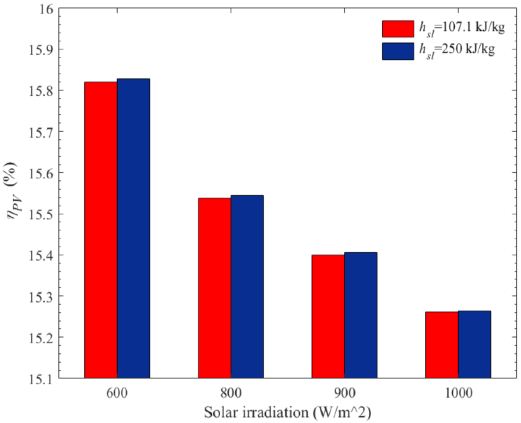
  • Increasing solar irradiation led to higher surface temperature and lower efficiency. The PV efficiency was maximised under irradiation of 600 W/m2 and the latent heat of 250 kJ/kg.
  • The PV temperature was significantly reduced when the mass flow rate increased. In addition, the temperature uniformity and output power were improved by increasing the mass flow rate.
  • Smaller jet-to-surface distances improved the PV output power, and the minimum PV temperature of 33.8 °C was obtained at H = 5.1 mm.
Future research on PV/JIC systems is proposed to study PCMs and pulsation jets providing higher efficiency.

Author Contributions

Conceptualization, J.M.; methodology, J.M.; software, J.M.; validation, J.M.; formal analysis, J.M.; investigation, F.S.; resources, F.S.; writing—original draft preparation, J.M.; writing—review and editing, F.S. and A.L.; visualization, J.M.; supervision, F.S. and A.L. All authors have read and agreed to the published version of the manuscript.

Funding

This research received no external funding.

Data Availability Statement

Data are contained within the article.

Conflicts of Interest

The authors declare no conflict of interest.

References

  1. Rahimi, M.; Valeh-E-Sheyda, P.; Parsamoghadam, M.A.; Masahi, M.M.; Alsairafi, A.A. Design of a self-adjusted jet impingement system for cooling of photovoltaic cells. Energy Convers. Manag. 2014, 83, 48–57. [Google Scholar] [CrossRef]
  2. Javidan, M.; Moghadam, A.J. Experimental investigation on thermal management of a photovoltaic module using water-jet impingement cooling. Energy Convers. Manag. 2021, 228, 113686. [Google Scholar] [CrossRef]
  3. Poulek, V.; Matuška, T.; Libra, M.; Kachalouski, E.; Sedláček, J. Influence of increased temperature on energy production of roof integrated PV panels. Energy Build. 2018, 166, 418–425. [Google Scholar] [CrossRef]
  4. Khodadadi, M.; Sheikholeslami, M. Numerical simulation on the efficiency of PVT system integrated with PCM under the influence of using fins. Sol. Energy Mater. Sol. Cells 2021, 233, 111402. [Google Scholar] [CrossRef]
  5. Salem, M.; Ali, R.; Elshazly, K. Experimental investigation of the performance of a hybrid photovoltaic/thermal solar system using aluminium cooling plate with straight and helical channels. Sol. Energy 2017, 157, 147–156. [Google Scholar] [CrossRef]
  6. Nahar, A.; Hasanuzzaman, M.; Rahim, N. Numerical and experimental investigation on the performance of a photovoltaic thermal collector with parallel plate flow channel under different operating conditions in Malaysia. Sol. Energy 2017, 144, 517–528. [Google Scholar] [CrossRef]
  7. Awad, M.; Radwan, A.; Abdelrehim, O.; Emam, M.; Shmroukh, A.N.; Ahmed, M. Performance evaluation of concentrator photovoltaic systems integrated with a new jet impingement-microchannel heat sink and heat spreader. Sol. Energy 2020, 199, 852–863. [Google Scholar] [CrossRef]
  8. Olawole, O.C.; Joel, E.S.; Ikono, U.I.; Moses, C.; Oyedepo, S.O.; De, D.K.; Nguyen, H.M.; Omeje, M.; Akinpelu, A.; Fobagboye, L.; et al. Innovative methods of cooling solar panel: A concise review. J. Physics Conf. Ser. 2019, 1299, 012020. [Google Scholar] [CrossRef]
  9. Zenhäusern, D.; Bamberger, E.; Baggenstos, A.; Häberle, A. PVT Wrap-Up: Energy Systems with Photovoltaic Thermal Solar Collectors; SwissEnergy: Bern, Switzerland, 2017. [Google Scholar]
  10. Sorensen, H.; Zondag, H. PV Catapult/European Collaboration for Identification of PV Research and Markets Opportunities, Socio-Economics, Studies, Performance Assessment and Dissemination of PV and PV–Thermal Technology. Available online: https://www.wip-munich.de/projects/project-pv-catapult/ (accessed on 21 September 2022).
  11. Zondag, H.A.; Vries, D.; van Steenhoven, A.A.; van Helden, W.G.; van Zolingen, R.J. Thermal and electrical yield of a combi-panel. In Proceedings of the ISES Bi-Annual Conference on CD-ROM, Jerusalem, Israel, 4–9 July 1999. [Google Scholar]
  12. Michael, J.J.; Iniyan, S.; Goic, R. Flat plate solar photovoltaic–thermal (PV/T) systems: A reference guide. Renew. Sustain. Energy Rev. 2015, 51, 62–88. [Google Scholar] [CrossRef]
  13. Nadda, R.; Kumar, A.; Maithani, R. Efficiency improvement of solar photovoltaic/solar air collectors by using impingement jets: A review. Renew. Sustain. Energy Rev. 2018, 93, 331–353. [Google Scholar] [CrossRef]
  14. Bahaidarah, H.M. Experimental performance evaluation and modeling of jet impingement cooling for thermal management of photovoltaics. Sol. Energy 2016, 135, 605–617. [Google Scholar] [CrossRef]
  15. Mohammadpour, J.; Lee, A. Investigation of nanoparticle effects on jet impingement heat transfer: A review. J. Mol. Liq. 2020, 316, 113819. [Google Scholar] [CrossRef]
  16. Mohammadpour, J.; Salehi, F.; Sheikholeslami, M.; Lee, A. A computational study on nanofluid impingement jets in thermal management of photovoltaic panel. Renew. Energy 2022, 189, 970–982. [Google Scholar] [CrossRef]
  17. Javidan, M.; Moghadam, A.J. Effective cooling of a photovoltaic module using jet-impingement array and nanofluid coolant. Int. Commun. Heat Mass Transf. 2022, 137, 106310. [Google Scholar] [CrossRef]
  18. Khanjari, Y.; Pourfayaz, F.; Kasaeian, A.B. Numerical investigation on using of nanofluid in a water-cooled photovoltaic thermal system. Energy Convers. Manag. 2016, 122, 263–278. [Google Scholar] [CrossRef]
  19. Mustafa, W.; Othman, M.; Fudholi, A. Numerical investigation for performance study of photovoltaic thermal nanofluids system. Int. J. Appl. Eng. Res. 2017, 12, 14596–14602. [Google Scholar]
  20. Wu, W.; Bostanci, H.; Chow, L.; Ding, S.; Hong, Y.; Su, M.; Kizito, J.; Gschwender, L.; Snyder, C. Jet impingement and spray cooling using slurry of nanoencapsulated phase change materials. Int. J. Heat Mass Transf. 2011, 54, 2715–2723. [Google Scholar] [CrossRef]
  21. Zhang, C.; Wang, T.; Chen, D.; Hong, F.; Cheng, P. Confined jet array impingement cooling with spent flow distraction using NEPCM slurry. Int. Commun. Heat Mass Transf. 2016, 77, 140–147. [Google Scholar] [CrossRef]
  22. Rehman, T.-U.; Ali, H.M. Experimental study on the thermal behavior of RT-35HC paraffin within copper and Iron-Nickel open cell foams: Energy storage for thermal management of electronics. Int. J. Heat Mass Transf. 2020, 146, 118852. [Google Scholar] [CrossRef]
  23. Rehman, T.-U.; Ali, H.M. Thermal performance analysis of metallic foam-based heat sinks embedded with RT-54HC paraffin: An experimental investigation for electronic cooling. J. Therm. Anal. 2020, 140, 979–990. [Google Scholar] [CrossRef]
  24. Bouadila, S.; Baddadi, S.; Rehman, T.-U.; Ayed, R. Experimental investigation on the thermal appraisal of heat pipe-evacuated tube collector-based water heating system integrated with PCM. Renew. Energy 2022, 199, 382–394. [Google Scholar] [CrossRef]
  25. Rehman, T.-U.; Ambreen, T.; Niyas, H.; Kanti, P.; Ali, H.M.; Park, C.-W. Experimental investigation on the performance of RT-44HC-nickel foam-based heat sinks for thermal management of electronic gadgets. Int. J. Heat Mass Transf. 2022, 188, 122591. [Google Scholar] [CrossRef]
  26. Kuravi, S.; Kota, K.M.; Du, J.; Chow, L.C. Numerical Investigation of Flow and Heat Transfer Performance of Nano-Encapsulated Phase Change Material Slurry in Microchannels. J. Heat Transf. 2009, 131, 062901. [Google Scholar] [CrossRef]
  27. Mohammadpour, J.; Salehi, F.; Lee, A. Performance of nano encapsulated phase change material slurry heat transfer in a microchannel heat sink with dual-circular synthetic jets. Int. J. Heat Mass Transf. 2022, 184, 122265. [Google Scholar] [CrossRef]
  28. Rehman, M.M.U.; Qu, Z.; Fu, R.; Xu, H. Numerical study on free-surface jet impingement cooling with nanoencapsulated phase-change material slurry and nanofluid. Int. J. Heat Mass Transf. 2017, 109, 312–325. [Google Scholar] [CrossRef]
  29. Brackbill, J.; Kothe, D.; Zemach, C. A continuum method for modeling surface tension. J. Comput. Phys. 1992, 100, 335–354. [Google Scholar] [CrossRef]
  30. Mohammadpour, J.; Zolfagharian, M.M.; Mujumdar, A.S.; Zargarabadi, M.R.; Abdulahzadeh, M. Heat transfer under composite arrangement of pulsed and steady turbulent submerged multiple jets impinging on a flat surface. Int. J. Therm. Sci. 2014, 86, 139–147. [Google Scholar] [CrossRef]
  31. Evans, D.; Florschuetz, L. Cost studies on terrestrial photovoltaic power systems with sunlight concentration. Sol. Energy 1977, 19, 255–262. [Google Scholar] [CrossRef]
  32. Evans, D.L. Simplified method for predicting photovoltaic array output. Sol. Energy 1981, 27, 555–560. [Google Scholar] [CrossRef]
  33. Goel, M.; Roy, S.; Sengupta, S. Laminar forced convection heat transfer in microcapsulated phase change material suspensions. Int. J. Heat Mass Transf. 1994, 37, 593–604. [Google Scholar] [CrossRef] [Green Version]
  34. Liu, L.; Jia, Y.; Lin, Y.; Alva, G.; Fang, G. Performance evaluation of a novel solar photovoltaic–thermal collector with dual channel using microencapsulated phase change slurry as cooling fluid. Energy Convers. Manag. 2017, 145, 30–40. [Google Scholar] [CrossRef]
  35. Glaspell, A.W.; Rouse, V.J.; Friedrich, B.K.; Choo, K. Heat transfer and hydrodynamics of air assisted free water jet impingement at low nozzle-to-surface distances. Int. J. Heat Mass Transf. 2019, 132, 138–142. [Google Scholar] [CrossRef]
Figure 1. Configuration of the PV/JIC system. (a) Schematic diagram and (b) nozzle arrays.
Thermo 02 00026 g001
Figure 2. Validation of the present study. (a) Validation with the Exp. [33] and numerical [26] data, and (b) validation with PV/JIC experimental data [2].
Thermo 02 00026 g002
Figure 3. Effect of solar irradiation and latent heat on the PV temperature at c = 2%, = 0.045 kg/s, N = 8, and H = 30 mm.
Thermo 02 00026 g003
Figure 4. Comparison of velocity contours between two mass flow rates in the YZ-plane at c = 2%, I = 1000 W/m2, hsl = 107.1 kJ/kg, N = 8, and H = 30 mm. (a) = 0.045 kg/s and (b) = 0.12 kg/s.
Thermo 02 00026 g004
Figure 5. Effect of mass flow rates on the PV temperature and its uniformity at c = 2%, I = 1000 W/m2, hsl = 107.1 kJ/kg, N = 8, and H = 30 mm.
Thermo 02 00026 g005
Figure 6. Effect of nozzle-to-surface spacing on the surface temperature and PV efficiency at c = 2%, I = 1000 W/m2, hsl = 107.1 kJ/kg, = 0.12 kg/s, and N = 24.
Thermo 02 00026 g006
Table 1. Design parameters and thermophysical properties of PV components [4,14].
GlassPV CellsTedlarSubstrate
Thickness, t, (mm)40.30.50.5
Thermal conductivity, k, (W/mk)11480.033202
Specific heat capacity, Cp, (J/kg·K)5006771250903
Density, ρ, (kg/m3)2450233012002702
Absorptivity, α0.050.90.128-
Transmissivity, τ0.920.09--
Emissivity, ε0.85---
Table 2. Thermophysical properties of water and NEPCM [20].
Materialsρ (kg/m3)k (W/m·K)Cp (J/(K·kg))
Water9970.614180
Octadecane (core)8500.341800
Polystyrene (shell)12600.212130
Table 3. The variation range of important parameters.
Parameter Variation Range
Solar irradiation (W/m2)I600–1000
Latent heat (kJ/kg)hsl107.1–250
Inlet mass flow rate (kg/s)0.045–0.12
Number of nozzlesN8–24
Jet-to-surface spacing (mm)H5.1–55
Table 4. Correlations for modelling effective physical properties [27].
PropertiesCorrelation
Density ρ s l u r r y = c ρ p + ( 1 c ) ρ w
where c is the volumetric concentration of particles.
Dynamic viscosity μ s l u r r y = ( 1 c 1.16 c 2 ) 2.5 μ w
Thermal conductivity k s l u r r y = k b ( 1 + B c P e p m )
k b = k w ( k p + 2 k w + 2 ( k p k w ) c ) / ( k p + 2 k w ( k p w ) c )
{ B = 3 ,   m = 1.5 ,   P e p < 0.67                               B = 1.8 ,   m = 0.18 ,   0.67 < P e p < 250 B = 3 ,   m = 1 11 ,   P e p < 250                                   and P e p = e d p 2 α b f
where e and α are the shear rate magnitude and thermal diffusivity, respectively [27].
Specific heat capacity C p , s l u r r y = ( 1 c m ) C p , w + c m C p , p + c m Υ [ { π 2 ( h s l T M R C p , p ) sin π [ ( T T s ) T M R ] } ] ,   Υ   = 0 or 1
where c m is the mass concentration of particles. h s l is the latent heat, T s is the solidus temperature, and T M R is the melting range.
Table 5. Effect of mass flow rate on economic factors at c = 2%, I = 1000 W/m2, hsl = 107.1 kJ/kg, N = 8, and H = 30 mm.
(kg/s)%P(max)increase
0.04514.99
0.0716.01
0.09516.76
0.1217.32
Table 6. Effect of number of IJs on the PV temperature and PV efficiency at c = 2%, I = 1000 W/m2, hsl = 107.1 kJ/kg, = 0.12 kg/s, and H = 30 mm.
Nozzle No.TPV (°C) η P V  
837.5515.56
1234.8815.76
1634.7715.77
2034.7515.78
2434.3115.81
Publisher’s Note: MDPI stays neutral with regard to jurisdictional claims in published maps and institutional affiliations.

