Technical Note

Construction Methods and Lessons Learned for a Non-Proprietary Ultra-High Performance Concrete Overlay

1
Department of Civil Engineering, New Mexico State University, P.O. Box 30001, MSC-3CE, (3035 S. Espina St.), Las Cruces, NM 88003, USA
2
Department of Civil and Environmental Engineering and Earth Sciences, University of Notre Dame, 156 Fitzpatrick Hall of Engineering, Notre Dame, IN 46556, USA
*
Author to whom correspondence should be addressed.
Constr. Mater. 2024, 4(1), 271-291; https://doi.org/10.3390/constrmater4010015
Submission received: 4 January 2024 / Revised: 6 February 2024 / Accepted: 21 February 2024 / Published: 22 February 2024

Abstract

:
The work presented in this paper includes the construction methods and lessons learned from the placement of a non-proprietary ultra-high performance concrete (UHPC) overlay through the rehabilitation of a concrete bridge deck located in Socorro, New Mexico, USA. The selected bridge is a multi-cell, box girder bridge with four spans and a total length of 91.4 m and a width of 16.5 m with two traffic lanes. Rehabilitation of the bridge involved removing the top surface of the existing deck (deteriorated concrete), installing a high-performance deck (HPD) leveling course, and placing a 25 mm UHPC overlay. Sensors were installed in the bridge superstructure (multi-cell box girders, HPD, and overlay) for long-term monitoring. Overlay assessment included physical testing to evaluate the condition of the overlay–substrate bond by chain dragging and direct tension pull-off testing. Conclusions and lessons learned from this investigation serve as a fundamental list of best practices and recommendations for field construction of a non-proprietary UHPC overlay. Recommendations for preparatory tasks including material selection, substrate surface preparation, placement preparation, handling of materials, and UHPC mixing are provided. The recommendations also list best practices concerning the placement of the overlay, curing procedures, and quality assurance testing. Lastly, suggestions are presented for contracts pertaining to UHPC overlay projects.

1. Introduction and Background

Normal-strength concrete (NSC) bridge decks have proved to deteriorate due to various factors, including poor initial quality and both environmental and mechanical distress [1]. Deterioration reduces the load capacity of the bridge and shortens its longevity, thus requiring rehabilitation of the bridge deck or even complete replacement. Overlay protective systems and other protection alternatives have been used to extend the lives of NSC bridge decks. The use of an overlay as a method of bridge preservation is beneficial when a concrete bridge deck is structurally sound but the surface of the deck is beginning to exhibit excessive deterioration [2]. Overlays provide a new wearing surface and improve cover to protect reinforcing steel. Numerous overlay materials have been used by transportation agencies, such as conventional concrete, high-performance concretes (HPCs), asphalt, and polymer-based materials [3,4]; however, they often have disadvantages such as elevated maintenance cost and limited service life.
Ultra-high performance concrete (UHPC) is a high-strength concrete material with a very dense microstructure that exhibits exceptional compressive strength and durability properties [2,3,5,6,7]. In addition, it also has improved flexural (tensile) strength and ductility due to the addition of high-strength steel fibers to its composition. These improved characteristics and properties make UHPC a suitable solution to serve as a protective overlay [8,9,10]. UHPC has been used in the USA for bridge construction since 2006, and from 2013 to 2020, more than 40 USA bridges have employed UHPC for retrofit applications [11]. Although UHPC characteristics provide many benefits, the high cost of the material constituents and the production of the proprietary products have restricted UHPC from becoming a widely used material for transportation infrastructure. However, the production of non-proprietary (developed with local materials and unpatented) UHPC mixtures can reduce production cost significantly [12,13,14]. The use of readily available materials to produce UHPC also helps to decrease cost and improve sustainability.
Previous research conducted in New Mexico, USA in collaboration with the New Mexico Department of Transportation (NMDOT) focused on the production of non-proprietary UHPC using materials local to New Mexico, USA with the objective of creating economical mixture proportions, while achieving the desired strength and durability requirements and improving the sustainability of the materials [12,13,15]. Mixture proportion investigations were assessed to account for different bridge superstructure applications, such as prestressed concrete beams, bridge joints, and concrete bridge deck overlays [12]. To assess the potential of non-proprietary UHPC as an alternative to typical overlay materials, numerous small-scale laboratory tests were performed to investigate the bond strength, shrinkage, and coefficient of thermal expansion of the UHPC. Then, large-scale testing was conducted to examine the combined shrinkage and thermal effects on conventional concrete slabs overlaid with the non-proprietary UHPC. Lastly, a large-scale laboratory test was performed to evaluate a full-scale prestressed channel girder with a 25 mm UHPC overlay under cyclic and ultimate flexural loads [13]. The findings from these tests suggested that the locally developed UHPC shows promise as an overlay material over NSC bridge decks.
The UHPC mixture proportions of the selected mixture for the overlay project are shown in Table 1. Type I/II Portland cement and fine sand with a maximum aggregate size of 4.75 mm were used. The steel fibers for the recommended mixture proportions were 13 mm long, with a length-to-diameter aspect ratio of 22 and a tensile strength that complies with the standards of ASTM A820 [16]. The selected UHPC mixture exhibited an average compressive strength of approximately 96.5 MPa after 28 days of ambient curing. For overlay applications, the overlay material bonding performance and durability is more imperative than its compressive strength. Several studies indicate that other major factors determining an overlay service life such as the overlay bond strength are more important than compressive strength [17,18,19,20]. Other factors such as substrate strength, absence of microcracks, cleanliness, overlay compaction, and overlay curing are also important but were considered constant for this project.
This study’s primary objective was to implement a non-proprietary UHPC overlay during rehabilitation of an existing concrete bridge deck in Socorro, NM, USA. The UHPC overlay was effectively installed through four placements from 10 April 2021 to 27 April 2021. Additionally, this paper evaluates the performance of the overlay through material testing and bond assessment. The findings from this investigation provides insight for bridge engineers on the potential new application of non-proprietary UHPC as an overlay material on bridge decks, which assists in moving forward with new and efficient ways of addressing bridge deterioration.

2. Methodology

The subsequent sections provide details about the description of the bridge, condition of the existing deck, removal of the deteriorating concrete and the design of the rehabilitated bridge deck, sensor instrumentation, high-performance deck (HPD) and UHPC placement, and test methodology from UHPC material sampling and overlay–substrate bond assessment.

2.1. Bridge Description

Bridge no. 7032 located in Socorro, NM, USA is the selected bridge on which the non-proprietary UHPC overlay was placed. The bridge is approximately 91.4 m in length and 16.5 m in width and has two traffic lanes separated by a center median. This structure is a box girder bridge consisting of four spans supported by three intermediate column bents (integral caps), and each integral bent cap contains six cylindrical columns as shown in Figure 1. During a site visit, an assessment of the condition of the existing concrete deck prior to its removal was performed. Access to the underside of the deck was possible through openings in the box girders near the abutments.

2.2. Condition of Existing Concrete Bridge Deck

Transverse cracks up to 1.59 mm in width (at a temperature of 22 °C at the time of measurement) were observed at several locations along the bridge deck as shown in Figure 2. The transverse cracks, potentially full depth, were mainly located at the negative moment regions over column bents. From a 2019 NMDOT inspection report, it was noted that the entire bridge deck presented cracking in “condition state three (CS3)—Poor” from a “CS1—Good” to “CS4—Severe” element condition rating. Additionally, 6.71 m showed exposed rebar in CS3—Poor, and 11.0 m exhibited spall/delamination/patching in CS2—Fair. As for the component condition rating, both the deck and superstructure were rated as “5—Fair” from a “0—Failed” to “9—Excellent” rating scale [21].

2.3. Removal of Deteriorated Concrete and Design of Rehabilitated Bridge Deck

The rehabilitation for bridge no. 7032 was initiated with the removal of the deteriorated concrete from the existing deck through hydro-demolition. The required depth of the concrete removal was a minimum of 19 mm below the deck transverse reinforcing steel, which was an anticipated depth of deck removal between 76 and 114 mm. Figure 3 shows the bridge before and after the initial deck removal. The deteriorated concrete removal involved removing the concrete deck overhang and the existing metal railing as observed in Figure 3b. Additionally, the expansion joint seals were removed and replaced.
The construction design for the bridge deck included installation of an HPD leveling course to restore the original deck elevation and placement of a 25 mm UHPC overlay. Figure 4 presents the rehabilitated (a) bridge plan view, (b) cross-sectional view, and (c) deck cross-sectional view. The design for the bridge rehabilitation additionally included new 0.91 m wide deck overhangs, 0.84 m high concrete barrier railings, and a 1.2 m wide raised median.

2.4. Sensor Instrumentation

External and embedded sensors (strain gauges and thermocouples) were installed to monitor the performance of the bridge superstructure [15]. First, external sensors were placed on the multi-cell box girder ceilings (underside of the deck), while embedded sensors were placed within the HPD and the UHPC overlay as seen in Figure 4c. Embedded sensors in the HPD were installed on the deck reinforcement prior to casting of the concrete. Embedded sensors in the UHPC were attached to 102 mm long steel bolts with steel nuts on the edges resting on the HPD prior to the placement of the overlay. A total of 156 strain gauges and 24 thermocouples were installed in the bridge. The strain gauges assisted in measuring compressive and tensile deformations at the bridge locations shown in Figure 4. The thermocouples were used to measure the temperature near strain gauge locations.

2.5. HPD Placement

After removal of the deteriorated concrete, the exposed deck and reinforcing steel were cleaned of debris and contaminants through pressure washing with water. Prior to placing the HPD, the concrete surface was dry. The HPD was placed by a concrete pump and secured with the steel reinforcement to the substrate, then consolidated, and screeded. The concrete surface was then floated and textured using a tine rake. The tined surface texture depth was at least 6.35 mm, meeting the minimum depth recommendations as per ACI 546 [22] for applying repair concrete.
Initial HPD placement started on the westbound lane on 30 November 2020. Casting was initiated on the east end of the bridge at approximately 9:00 a.m. and concluded by evening, around 6:00 p.m. The following HPD placement (eastbound lane) took place on 1 March 2021. Casting began from the west end of the bridge at around 11:00 a.m. and was finished by the evening, approximately at 5:00 p.m. Figure 5 shows the HPD (a) placement and (b) finish.

2.6. UHPC Overlay Placement

2.6.1. Substrate Surface Preparation

Prior to overlay installation, the substrate (HPD) surface was prepared by providing a roughened texture. The surface texture was attained through a ceramic bead blaster. Subsequently, the HPD was kept saturated up to placement of the UHPC overlay. Substrate surface preparation is paramount since improper surface texturing and pre-wetting of the substrate concrete can result in a lack of bond [23,24,25].

2.6.2. Material Preparation and Mixing

The basis for each batch volume was bags of silica fume weighing 11.3 kg each. The material preparation involved pre-filling bags with sand, cement, and fly ash to reduce the batching time. Bags contained the weights required for a 0.59 m3 batch volume. The remaining constituents (silica fume, water, HRWRA, and steel fibers) were weighed and added separately.
The UHPC was mixed on site in two high-energy horizontal shaft mixers with a 0.76 m3 volumetric capacity. The mixing process consisted of first adding the dry materials from the prefabricated bags (sand, cement, and fly ash) into the mixers, then silica fume was added separately. Dry mixing was performed for about 30 s to a minute, then approximately 80% of the total amount of water was added, followed by the HRWRA. The remaining 20% of water was added gradually to account for the extra moisture content in the sand and to avoid passing the desired consistency of UHPC. The batch continued to mix until a workable paste was obtained. At this point, the steel fibers were added and mixing continued for another two minutes. After mixing was concluded, the UHPC temperature, slump, and spread were recorded.

2.6.3. Production Placements

Installation of the UHPC overlay was segmented into four production placements (two placements allocated per lane). The initial production placement commenced on 10 April 2021 from the west end of the bridge at approximately 10:00 p.m. and was stopped via a construction joint the following day by noon (12:00 p.m.). Then, the second production placement resumed on 13 April 2021 around midnight (12:00 a.m.) and finalized around 5:00 a.m. The third production placement was cast on 24 April 2021 beginning from the east end of the bridge at 2:00 a.m. and was paused with a construction joint the same day by 7:00 a.m. The final placement was resumed on 27 April 2021 at around 9:00 p.m. and concluded the following morning at approximately 5:00 a.m. Figure 6 shows the overlay placement and finish. Production of the UHPC overlay resulted in a total of 105 batches (53 batches for the eastbound lane and 52 batches for the westbound lane). UHPC samples were collected for compressive and flexural strength quality control testing to meet the NMDOT requirements.
An evaporation retardant (Confilm®) was used during the placement and finish of the UHPC. However, visible cracking resulted from the first production placement. The overlay was not promptly covered with plastic sheets and wet burlap after completion of the surface finish. As a result, isolated cracks were visible when removing the plastic sheets and burlap, as can be observed in Figure 7. Visible cracking was mainly located near the construction joint where the first production placement concluded. After the first placement, the subsequent placements of the UHPC overlay were immediately covered with plastic sheets as the surface finish was being completed to reduce evaporation and related cracking. Only isolated cracking was observed for the remaining production placements due to the improved curing procedures.

2.6.4. Preparation of Specimens and Curing Procedures

Cube (100 mm) and prismatic (76 × 102 × 406 mm) specimens were cast in steel molds. All steel molds were lightly oiled prior to the placement of concrete to facilitate de-molding of the UHPC. Casting included rodding the UHPC to ensure consolidation. Cast samples were placed in a shaded area under ambient field conditions and covered with a plastic sheet to prevent moisture loss. Specimens remained covered at ambient field conditions for at least 24 h. The specimens were then transported (approximately 24 h after casting) for two hours to the testing laboratory. Upon arrival, the samples were de-molded and the laboratory curing procedures commenced. A total of 24 cube samples and eight prismatic specimens were prepared from each production placement. Curing of the cube samples consisted of exposing half of the total specimens to ambient laboratory conditions (20 °C and 30% relative humidity [RH]) for early strength testing (2, 4, and 7 days of curing) and the remaining half in a moist curing room (23 °C and 98% RH) for 14, 28, and 56-day testing. Curing of the prismatic samples consisted of curing all specimens in a moist room for seven days, then under ambient laboratory conditions until testing.

2.7. Test Methodology

Testing initiated with the measurement of the temperature and workability of the mixtures while in the plastic state. Slump [26] and slump-flow tests [27] were performed on most batches. Since both horizontal mixers were mixing simultaneously, some batches were completed at the same time, and both could not be tested. Target slump and slump-flow measurements were identified to be between 216 and 254 mm and between 305 and 495 mm, respectively, since mixtures with lower slumps presented challenges while handling, placing, and finishing. In the hardened state, compressive and flexural strength tests were conducted on UHPC specimens.
Evaluation of the bond between the concrete substrate and the UHPC overlay was conducted on bridge no. 7032. Physical tests including hammer sounding and chain dragging were used to assess any potential delamination of the overlay. Additionally, bond strength and confirmation of delaminated areas were evaluated by coring and conducting pull-off tests on various locations across the bridge.

2.7.1. Slump and Slump-Flow Testing

To evaluate the workability of the UHPC, both slump and slump-flow tests were performed on mixtures according to ASTM C143 [26] and ASTM C1611 [27], respectively, as illustrated in Figure 8. A standard steel slump cone with a base diameter of 203 mm, a top diameter of 102 mm, and height of 305 mm was used. For both slump and slump-flow tests, the slump cone was positioned upright on a stainless steel base plate. The UHPC was then cast into the cone in three segments (each equivalent to 1/3 of the cone volume). After each increment, the mixture was rodded 25 times. As the slump cone was being filled, a slight downward force was applied to the cone to prevent it from moving and to avoid the UHPC from escaping the bottom of the slump cone. Once the cone was filled, the UHPC top surface was troweled evenly with the top rim of the slump cone. Subsequently, the cone was slowly and steadily lifted in a single vertical motion, allowing the UHPC to slump and spread. Slump and spread measurements were taken to the nearest 5 mm using a tape measure. For slump measurements, the cone was turned upside down, and a steel rod was placed level on the top of the slump cone. The slump was measured as the difference between the top of the UHPC mixture and the bottom of the rod using a tape measure as seen in Figure 8a. The spread of the UHPC was then determined by averaging three measurements across the width of the slumped UHPC as seen in Figure 8b.

2.7.2. Compressive Strength Testing

UHPC compression tests were conducted in compliance with the British Standard (BS) 1881 [28] on 100 mm cube specimens at 2, 4, 7, 14, 28, and 56 days. Each testing day involved the evaluation of a minimum of four cube samples. Specimens were loaded to failure (as seen in Figure 9) at a rate of 62 MPa/min following recommendations to accelerate testing on UHPC by Graybeal [5]. Target compressive strengths were identified to be 68.9 MPa at seven days and 117.2 MPa at 56 days. The selected target strengths were provided by the NMDOT.

2.7.3. Flexural Strength Testing

Flexural strength of the UHPC was assessed by conducting flexural tests similar to tests described in ASTM C1609 [29]. Tests were performed on 76 × 102 × 406 mm prismatic specimens at 7, 14, 28, and 56 days. Results were expressed as modulus of rupture (MOR). A minimum of two prismatic samples were tested for each testing day. The four-point flexural tests were conducted by placing a UHPC sample over two bearing points (one at each end of the specimen), followed by applying a load at two points on the top of the sample near midspan, as illustrated in Figure 10. Flexural tests included using load cells, linear-variable displacement transducers, and string potentiometers to monitor the loads and deformations of specimens. The monitoring assisted in identifying the first crack load, which was then used to determine the flexural strength (MOR) of the prismatic specimens. The prisms were subjected to failure by loading at a rate of 6.7 kN per minute.

2.7.4. Chain Dragging and Pull-Off Testing

Physical testing was conducted over the entire UHPC overlay to identify any potential delaminated areas by performing hammer sounding and chain dragging. The chain drag is an acoustic technique, which involves dragging a mop-like tool (a steel rod with a handle and several chains attached at the bottom) across the surface of a bridge (e.g., deck or overlay). This method is based on the tone produced (sound or delaminated) throughout chain dragging. Areas in good condition will produce a distinct high-pitched tone, whereas delaminated areas will have a lower tone (hollow sound). Chain dragging was conducted twice a year in 2021 and 2022 (17 May 2021, 16 December 2021, 25 April 2022, and 5 August 2022).
Direct tension pull-off testing was performed on identified potential delaminations and intact areas by following ASTM C1583 [30]. First, a 47.6 mm in diameter core drill was used to penetrate through the UHPC overlay and about 38.1 mm into the concrete substrate. A wood core drilling base was used for steadier drilling as shown in Figure 11a. A water hose was connected to the core drill to lubricate and cool the drill when used. After drilling to the desired depth (around 63.5–76 mm), the core samples’ top surfaces were allowed to dry and cleaned of any debris. Steel plates were then attached to the core samples by applying a two-component fast-curing epoxy (ASF-GEL). Direct tension pull-off tests were performed by using a Hydrajaws M2050 Pull Tester as seen in Figure 11b. ACI 546 [22] recommends a minimum tensile bond strength of 1.0 MPa and considers an “excellent” bond strength greater than or equal to 1.72 MPa.

3. Results and Discussion

During UHPC overlay placements, temperature and workability measurements were recorded for each batch. Subsequently, cube and prismatic samples were taken for compressive and flexural strength tests, respectively. Lastly, overlay–substrate bond assessment including chain dragging and direct tension pull-off testing were performed to evaluate the potential delamination of the overlaid UHPC.

3.1. Temperature and Workability of the UHPC

The evaluation of the UHPC overlay placement was initiated with the measurement of temperature and workability for each batch mixture. Table 2 presents the average UHPC temperature, slump, and slump-flow values from all production placements. Table A1 (shown in Appendix A) presents the temperature and workability measurements from each UHPC batch. A total of 110 batches were mixed; however, 105 batches were accepted and placed on the bridge deck. Five batches were rejected due to not meeting the desired consistency (too wet or too dry due to overmixing). As seen from Table 2, the average temperatures ranged from 19.6 °C to 23.7 °C. The UHPC temperatures are comparable since all four overlay placements took place late at night and during similar weather temperatures (10–16 °C). As previously mentioned, the target slump measurements were between 216 and 254 mm and the target spread range was between 305 and 495 mm. In general, the average UHPC temperature, slump, and slump-flow values for the 105 overlaid batches were 22.1 °C, 235 mm, and 405 mm, respectively.

3.2. UHPC Strength Results

The UHPC strength results from the overlay production placements are shown in Table 3. For compressive strength, cube specimens tested at 2, 4, and 7 days were exposed to ambient (labeled as “A”) laboratory conditions at 20 °C and 30% RH. The cube specimens tested at 14, 28, and 56 days were stored in a moist curing room (labeled as “MR”) at 23 °C and 98% RH until testing. For flexural strength, prismatic specimens were moist room-cured for seven days and then cured under ambient laboratory conditions until their respective testing day. From the results, all production placements passed the target compressive strength of 68.9 MPa at seven days. However, no production placement met the target compressive strength of 117.2 MPa at 56 days. Production Placement 3 exhibited an average 56-day compressive strength of 96.9 MPa. Production Placement 1 had the lowest average 56-day compressive strength of 88.1 MPa. The compressive strength gain observed was typical for the material constituents used in the UHPC [12,13,15]. MOR strengths decreased significantly after seven days of moist curing. This decrease in flexural strength is attributed to the hydration stoppage and dry curing that took place after seven days, which may have induced stresses (shrinkage) at the surface of the prismatic specimens (extreme fiber location in flexure). This may have caused stresses near individual fibers that restrained shrinkage.
The limited strengths observed for the field samples are attributed to the challenges during the overlay production placements. Field curing of the samples was performed at ambient conditions for the first 24 h by covering the steel molds with plastic sheets. During this period, the plastic sheets may have not been in close contact with the concrete surface at all times, therefore resulting in some moisture loss from the samples. Additionally, there was insufficient precise control on the water content of the field batches and not adequate control on the early curing temperature of the specimens. Particularly, mixing of the field batches included controlling workability within an acceptable range of slump and slump-flow. The precise moisture contents of the accepted UHPC batches remained unknown since the moisture content of the pre-bagged sand was not known.
Figure 12 presents a compressive strength gain plot from all four UHPC production placements. It can be observed in Figure 12 that the first production placement exhibited the lowest strength gain behavior, while the following production placements improved and even reached similar ultimate strengths (approximately 96.5 MPa). At seven days, all production placements met the target compressive strength of 68.9 MPa by reaching strengths of 74.9 MPa, 76.9 MPa, 80.9 MPa, and 81.2 MPa, respectively. For the most part, improved compressive strengths were achieved as more production placements were batched, which suggests that the UHPC overall handling and production were improved.
Figure 13 shows the flexural strengths at 7, 14, 28, and 56 days in terms of MOR from the production placements. As seen in Figure 13, the UHPC for all placements followed a similar behavior. At seven days, while curing inside a moist room, samples had greater flexural strengths than other test days when samples were exposed to ambient laboratory conditions. All production placements varied in strength at the different testing ages, but for the most part, Production Placement 2 showed greater flexural strengths and Production Placement 3 showed lower strengths. There was a noticeable decrease in the strength of 4.03 MPa (37.3%) for Production Placement 3 from 7 to 14 days. Similarly, Production Placements 1, 2, and 4 decreased in strength from 1.59 MPa to 2.28 MPa (17–25%) from 7 to 14 days. Subsequently, strengths remained nearly constant from 14 to 56 days.

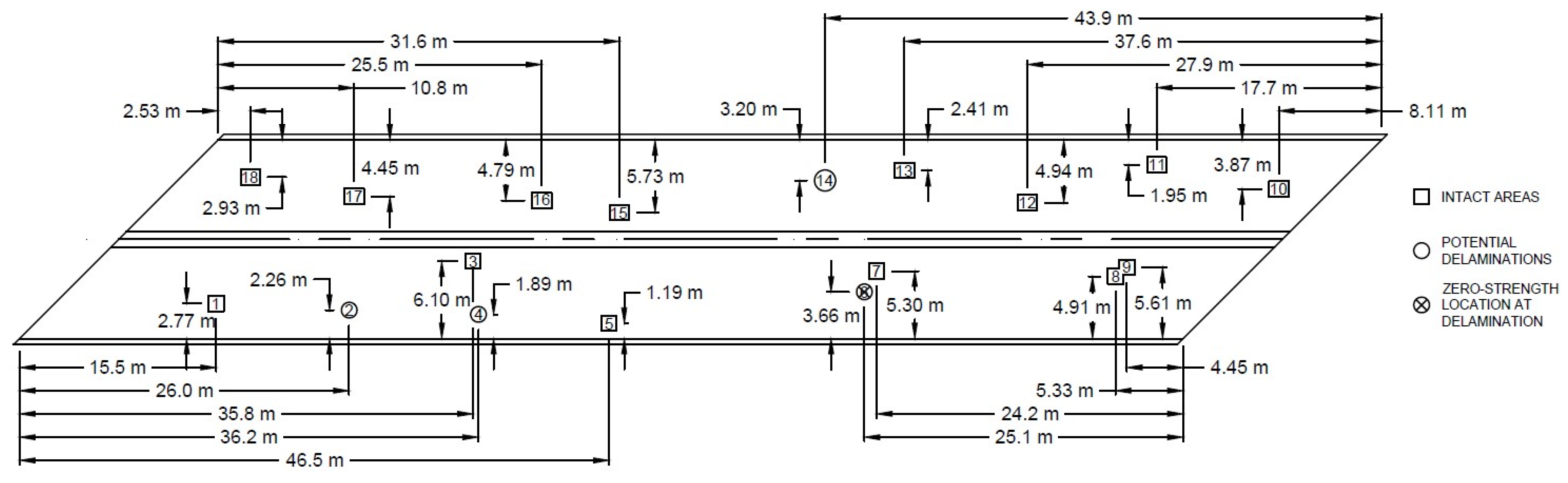
3.3. Overlay–Substrate Bond Assesment

Multiple chain drags were conducted on the bridge to monitor the potential development of delaminated areas due to flexural deformations from loads and temperature oscillations through season changes. Figure 14 presents the potential delamination areas identified. A total of 15 potential delaminations (0.19% out of the total bridge area) were identified: six on the westbound lane and nine on the eastbound lane. Most potential delamination areas were approximately 0.3 by 0.3 m, except for areas near the construction joints, which extended up to 1.5 by 0.3 m in length. The most recent chain dragging was conducted on 5 August 2022.
Direct tension pull-off tests were performed on potential delaminations and intact areas. The core drilling and pull-off test locations attempted on the bridge are shown in Figure 15. As illustrated, a total of 18 core drillings were attempted (nine on each lane). Four core samples were drilled on potential delaminated areas (core samples no. 2, 4, 6, and 14). However, only one core location could not be tested (core sample no. 6) since the overlay portion of the core debonded from the concrete substrate while coring, resulting in a zero-strength location. As with chain dragging, pull-off tests were last conducted on 5 August 2022.
Table 4 presents the tensile strengths and types of failure from the pull-off samples. A “Bond” failure is a failure at the bond interface between the HPD and the UHPC. A “UHPC/Epoxy” failure is a failure of the epoxied interface between the UHPC and the steel plate with some UHPC appearing on the fracture surface. Most locations were effectively tested and evidenced good strengths with only four samples (mainly on the eastbound lane) having bond strengths less than the minimum 1.0 MPa as recommended by ACI 546 [22]. Four tests were conducted on potential delaminated areas; however, only one proved to be delaminated by being a zero-strength location (0.01% out of the total bridge area). Looking at the bond strengths by lanes, the westbound lane had greater strengths than the eastbound lane. Most samples on the westbound lane passed the “excellent” tensile bond strength of 1.72 MPa with only one specimen having a bond strength less than the recommended 1.0 MPa. Improved overlay placement and curing procedures were followed for the westbound lane. These are potential factors to the development of delaminated areas on the eastbound lane. The average tensile bond strength for the westbound lane was 2.25 MPa, meanwhile the average tensile strength for the eastbound lane was 1.44 MPa. The average bond strength of all the 18 core samples was 1.88 MPa, surpassing the “excellent” bond strength of 1.72 MPa stated by ACI 546 [22].

4. Conclusions and Lessons Learned

The lessons learned from this investigation serve as a detailed list of best practices and recommendations for the field implementation of a non-proprietary UHPC overlay. The list outlines recommendations for preparatory tasks including material selection, preparation for placement, material handling, and mixing. Also included are recommendations regarding overlay placement, curing, quality assurance testing, and sensor instrumentation. Lastly, suggestions are provided for contracts pertaining to UHPC overlay projects.

4.1. Selection of Materials

The material selection of the UHPC overlay should include alternative material constituents available to produce acceptable mixtures in case a specific material becomes unavailable. For instance, if the mixture proportion calls for steel fibers produced internationally, flexibility to use alternative steel fibers produced domestically should be confirmed as adequate for use in case the Buy-America requirement on steel products is imposed. This precaution is essential because there is minimal opportunity to accommodate for a new UHPC mixture if adjustments are needed shortly before or after commencement of a project. Ensuring a robust mix design can offer assurance that the final product will meet performance expectations.
Contractors should exclusively use specified admixtures when dealing with a locally developed UHPC mixture. These admixtures should be clearly identified by product name and producer, ensuring that contractors only use admixtures that have been verified and accepted through laboratory testing to produce acceptable mixtures.

4.2. Substrate Surface Preparation

An appropriate surface texture must be ensured during substrate surface preparation of the concrete. Substrate surface preparation should begin by cleaning any debris from the surface and then applying either sandblasting or shotblasting to produce an acceptable surface texture. An acceptable substrate surface texture is obtained by removing surface paste and exposing fine aggregate. A minimum exposed fine aggregate surface texture of “light sandblasted texture” as specified by ACI 303 [31]. A second surface cleaning to remove any debris from the surface texture is imperative. Traffic must not be allowed on surface textured areas prior to the placement of the overlay.
Prior to overlay placement, the substrate surface should be preserved at saturated surface conditions for 24 h. Ensuring a visibly moist substrate surface before overlay placement is crucial for achieving bonding to any cementitious overlay material. Therefore, the substrate should be regularly supervised and maintained saturated up to the placement of the overlay.

4.3. Placement Preparation

Contractors must have an understanding of the overlay material regarding the mixing, handling (workability), placement, and curing. This familiarity and understanding enable contractors to select adequate mixer quantities and sizes to produce UHPC mixtures. This familiarity should also ensure a rate of no more than 15 min between successive overlay batch placements. Thoughtful preparation of the production placements may assist minimizing instances of cold joint formation.
Weather forecasts pertaining to the days of overlay placement should be closely monitored beforehand. This is of importance because the substrate needs to be in saturated surface conditions prior to overlay placement. Proper actions should be followed to ensure that the substrate surface conditions are met when placing the overlay.
UHPC is prone to plastic shrinkage, which can increase due to moisture loss. Moisture evaporation in the UHPC is particularly problematic because of the low water-to-cementitious material ratio (w/cm). If the rate of moisture loss surpasses 0.20 kg/m2/h, appropriate actions should be taken, such as postponing the overlay placement or planning measures to avoid the freshly placed UHPC from evaporating.

4.4. Handling of Materials

Aggregates should be stored in containers if these aggregates are to be weighed out for more than two hours before mixing to assist preserving the moisture content. Ensuring a known aggregate water content is imperative because it can affect the w/cm, consequently impacting the workability and overall strength of the UHPC.
Contractors must maintain cementitious materials and aggregates independently. The pre-bagging of cementitious materials with aggregates can result in early hydration of the cementitious materials due to the moisture content of the aggregates.

4.5. UHPC Mixing

Contractors must be familiar with moisture adjustments to manage the impact of aggregate moisture content on the w/cm prior to UHPC mixing. This familiarity enables the contractors to take prompt action on necessary adjustments if there are variations in aggregate moisture content between batches or if there are inconsistencies in moisture contents of the pre-batched aggregate containers.
Contractors should confirm the maximum volume capacity of the UHPC that can be safely mixed by the selected mixers. Due to the extreme stiffness of the UHPC during mixing, reaching the rated capacity of the mixer is questionable. Therefore, it is essential for contractors to determine batch volumes that can be safely and reliably mixed within a reasonable amount of time.
Prior to mixing of the UHPC on site, the mixer’s potential to produce a homogeneous UHPC paste must be confirmed.

4.6. UHPC Placement

Prior to the placement of the UHPC overlay, any areas on the substrate surface showing excessive moisture (ponding) must be swept. While it is paramount to maintain saturated surface conditions on the substrate before overlay placement, excessive moisture can affect the w/cm of the UHPC. Thus, it is recommended to sweep or sponge areas with excess moisture.
There may be events where the overlay production placement has to stop, resulting in the formation of a cold/construction joint. If this is the case, a pre-determined plan for cold joint procedures should be established and met. This plan should be developed and mutually agreed upon by the engineers, project manager, and contractor before initial overlay placement.

4.7. Overlay Curing

Curing compound for the overlay material should only be applied after finishing is completed. Mixing the curing compound in with the UHPC mixture can have negative effects on the concrete. Hence, application of the curing compound should be applied after completion of the overlay finishing.
Immediately after completing the UHPC overlay finish, the curing compound should be applied and then the overlay must be covered with plastic sheets. These curing procedures help minimize evaporation and related cracking.
Additional construction on the bridge (overlay grooving, median construction, etc.) should be performed at a time were the UHPC overlay has gained sufficient strength (a minimum overlay curing age of seven days) to prevent any induced stress at the bond interface. The longer the overlay is cured prior to further work on the bridge, the better.

4.8. Quality Assurance

Several overlay mock placements should be conducted, requiring contractors to properly execute the necessary procedures for placing the UHPC overlay adequately. The mock placement should not be approved until the contractor proves proficiency in all required procedures for placing the UHPC overlay under field conditions. As the bridge construction industry gets more familiar and experienced with the construction of UHPC overlays, the requirement for overlay mock placements may be decreased or removed.
Quality control testing should be mandatory for the acceptance of each batch of the UHPC prior to being overlaid. The UHPC testing area should be clear of obstructions and located as close as possible to the mixing area to guarantee prompt availability of test results.
Both slump and slump-flow tests must be performed to each UHPC batch. These tests enable the assessment of the consistency of the mixtures and can be used to determine the acceptance (or rejection) for each batch.
UHPC sampling on site for strength testing should be stored in curing chambers to secure them from any potential aggressive environment that may affect the strength development. As specified in ASTM C1856 [32], field concrete samples must be covered with a plastic sheet within one minute after completing the surface finish. Additionally, field concrete samples must undergo curing as stated in ASTM C31 [33] by placing them in a temperature-controlled chamber at 20 °C to 26 °C for the initial 48 h. Following the 48 h, samples must be de-molded and placed inside a moist curing room, at a temperature of 23 ± 2.0 °C.

4.9. Sensor Instrumentation

If a specific sensor instrumentation is to be installed, several laboratory tests should be conducted on sensors to analyze their readings and behavior. Full-scale tests should also include a similar sensor schematic to be installed for the project. It is paramount to expect a certain behavior prior to sensor installation on the bridge.
Contractors must be familiar with the sensor instrumentation to be installed to avoid losing a significant number of sensors. Sensors can be easily damaged during concrete placements due to heavy equipment on the bridge resulting in a loss of data.

4.10. General Contracts

When specifying non-proprietary UHPC, the organization related to the project should aim to reduce liability related with prescriptive specifications. The contractor’s capability to produce a UHPC overlay material should be considered in the bid for the project. As part of the contract, a performance-based specification for the UHPC overlay, including workability and strength gain requirements, should be specified. Requiring the contractor to produce a UHPC mixture meeting performance specifications reduces the necessity for prescriptive specifications that could potentially shift liability to the organization.

Author Contributions

Conceptualization, A.A., W.K.T., B.D.W. and C.M.N.; methodology, A.A., W.K.T., B.D.W. and C.M.N.; software, A.A., W.K.T., B.D.W. and C.M.N.; validation, A.A., W.K.T., B.D.W. and C.M.N.; formal analysis, A.A., W.K.T., B.D.W. and C.M.N.; investigation, A.A., W.K.T., B.D.W. and C.M.N.; resources, A.A., W.K.T., B.D.W. and C.M.N.; data curation, A.A.; writing—original draft preparation, A.A.; writing—review & editing, B.D.W. and C.M.N.; visualization, A.A., B.D.W. and C.M.N.; supervision, B.D.W. and C.M.N.; project administration, B.D.W. and C.M.N.; funding acquisition, B.D.W. and C.M.N. All authors have read and agreed to the published version of the manuscript.

Funding

This research was funded by the New Mexico Department of Transportation (NMDOT), project number R919030, and the Transportation Consortium of South-Central States (Tran-SET), project number 19CNMS01.

Data Availability Statement

The data presented in this study will be openly available upon publication of NMDOT final report project no. R919030.

Acknowledgments

The authors would like to thank and acknowledge NMDOT and Tran-SET for funding this project and their continuous support on UHPC research and additionally the work and collaboration from Structures, Inc. Lastly, a special thanks to Hao Yin, Shannon Vigil, Kathy Crowell, Gabriel Garcia, Earl Franks, Ben Najera, and Sean Brady for their technical support and direction.

Conflicts of Interest

The authors declare no conflicts of interest.

Appendix A

Table A1. Temperature and workability measurements from each UHPC batch.
Batch No.Temperature
(°C)
Slump
(mm)
Spread
(mm)
ACCEPTED/REJECTED
120.9270560ACCEPTED
2---REJECTED
322.2250490ACCEPTED
420.2235445ACCEPTED
522.1230390ACCEPTED
622.7220385ACCEPTED
719.5205355ACCEPTED
823.9220380ACCEPTED
924.4220385ACCEPTED
1024.7230395ACCEPTED
1123.0220385ACCEPTED
1220.6235420ACCEPTED
1322.4235415ACCEPTED
1419.3240455ACCEPTED
1518.2235410ACCEPTED
1618.6240445ACCEPTED
1721.8215340ACCEPTED
1820.6250490ACCEPTED
1921.6250475ACCEPTED
2021.1240380ACCEPTED
2121.7230370ACCEPTED
2220.6205355ACCEPTED
2321.4230380ACCEPTED
2422.2255385ACCEPTED
2522.0240430ACCEPTED
2622.2255380ACCEPTED
2723.8240410ACCEPTED
2823.3250435ACCEPTED
2923.4235415ACCEPTED
3019.8255440ACCEPTED
31---REJECTED
3220.6260435ACCEPTED
3321.2270440ACCEPTED
3422.3235415ACCEPTED
3524.4240385ACCEPTED
3624.9230360ACCEPTED
3725.4215340ACCEPTED
3824.4255380ACCEPTED
3924.0235420ACCEPTED
4024.2240415ACCEPTED
4124.7250460ACCEPTED
4225.4240440ACCEPTED
4325.5240420ACCEPTED
4425.1250450ACCEPTED
4527.0215360ACCEPTED
46---REJECTED
4722.9240440ACCEPTED
4824.6240435ACCEPTED
4923.8240400ACCEPTED
5023.9240435ACCEPTED
5120.2190295ACCEPTED
52---REJECTED
5324.2235380ACCEPTED
5426.5250400ACCEPTED
5523.4240380ACCEPTED
5621.9260430ACCEPTED
5721.1250400ACCEPTED
5819.0250430ACCEPTED
5916.5230385ACCEPTED
6019.4240435ACCEPTED
6117.8240410ACCEPTED
6220.6235415ACCEPTED
6322.0215365ACCEPTED
6420.6215340ACCEPTED
6520.8205335ACCEPTED
6620.9215360ACCEPTED
6720.4235380ACCEPTED
6819.6240405ACCEPTED
69Not testedNot testedNot testedACCEPTED
7020.4240430ACCEPTED
7118.5240430ACCEPTED
7219.8240390ACCEPTED
7318.2240410ACCEPTED
7419.1240415ACCEPTED
7518.7250430ACCEPTED
76Not testedNot testedNot testedACCEPTED
7726.4235370ACCEPTED
7823.8240400ACCEPTED
7923.4230375ACCEPTED
8024.5240420ACCEPTED
8125.4235380ACCEPTED
8225.4230385ACCEPTED
8325.4240410ACCEPTED
8424.3235380ACCEPTED
8525.5230375ACCEPTED
8620.7235395ACCEPTED
8721.1230360ACCEPTED
8821.7240380ACCEPTED
8921.2240420ACCEPTED
9022.6230375ACCEPTED
9124.2230380ACCEPTED
92Not testedNot testedNot testedACCEPTED
9322.2240430ACCEPTED
94Not testedNot testedNot testedACCEPTED
95Not testedNot testedNot testedACCEPTED
9622.1230375ACCEPTED
97Not testedNot testedNot testedACCEPTED
98Not testedNot testedNot testedACCEPTED
9921.9240430ACCEPTED
10024.0250440ACCEPTED
101Not testedNot testedNot testedACCEPTED
10224.0230380ACCEPTED
10320.8235435ACCEPTED
104Not testedNot testedNot testedACCEPTED
105Not testedNot testedNot testedACCEPTED
10620.9235385ACCEPTED
10722.6210340ACCEPTED
108Not testedNot testedNot testedACCEPTED
109Not testedNot testedNot testedACCEPTED
110Not testedNot testedNot testedNot placed

References

  1. Sritharan, S.; Doiron, G.; Bierwagen, D.; Keierleber, B.; Abu-Hawash, A. First Application of UHPC Bridge Deck Overlay in North America. Transp. Res. Rec. 2018, 2672, 40–47. [Google Scholar] [CrossRef]
  2. Muzenski, S.; Graybeal, B. Structural Performance of UHPC Overlays. In Proceedings of the International Interactive Symposium on Ultra-High Performance Concrete, Wilmington, DE, USA, 4–7 June 2023; Volume 3. [Google Scholar] [CrossRef]
  3. Haber, Z.B.; Munoz, J.F.; Graybeal, B.A. Field Testing of an Ultra-High Performance Concrete Overlay; FHWA-HRT-17-096; Federal Highway Administration: Washington, DC, USA, 2017. [Google Scholar]
  4. Lin, S.; Azari, H.; Meng, D.; Shams, S. Nondestructive Evaluation of Concrete Bridge Decks with Overlays; Final Report No. FHWA-HRT-21-023; Federal Highway Administration: Washington, DC, USA, 2021. [Google Scholar]
  5. Graybeal, B.A. Material Property Characterization of Ultra-High Performance Concrete; FHWA-HRT-06-103; Federal Highway Administration: Washington, DC, USA, 2006. [Google Scholar]
  6. Graybeal, B.; Davis, M. Cylinder or Cube: Strength Testing of 80 to 200 MPa (11.6 to 29 ksi) Ultra-High-Performance Fiber-Reinforced Concrete. ACI Mater. J. 2008, 105, 603–609. [Google Scholar] [CrossRef]
  7. Song, M.; Wang, C.; Cui, Y.; Li, Q.; Gao, A. Mechanical Performance and Microstructure of Ultra-High-Performance Concrete Modified by Calcium Sulfoaluminate Cement. Adv. Civ. Eng. 2021, 2021, 400253. [Google Scholar] [CrossRef]
  8. Graybeal, B.A.; Haber, Z. Ultra-High Performance Concrete for Bridge Deck Overlays; FHWA-HRT-17-097; Federal Highway Administration: Washington, DC, USA, 2018. [Google Scholar]
  9. Nault, G.; Samson, E. UHPC: A Durable Concrete Overlay Solution for Bridge Decks. In Proceedings of the 2019 IABSE Congress, New York, NY, USA, 4–6 September 2019. [Google Scholar]
  10. Kuncoro, A.; Pranoto, H.D.; Sacca, L.W.; Antoni, A.; Hardjito, D.; Tanojo, E. Evaluation of Bonding Performance of Ultra-High Performance Concrete with Fly Ash Content as Overlay on Normal Strength Concrete. IOP Conf. Ser. Earth Environ. Sci. 2023, 1195, 012020. [Google Scholar] [CrossRef]
  11. Haber, Z.B.; Foden, A.; McDonagh, M.; Ocel, J.; Zmetra, K.; Graybeal, B. Design and Construction of UHPC-Based Bridge Preservation and Repair Solutions; FHWA-HRT-22-065; Federal Highway Administration: Washington, DC, USA, 2022. [Google Scholar]
  12. Weldon, B.; Jauregui, D.; Newtson, C.; Montoya, K.; Taylor, C.; Allena, S.; Muro, J.; Tahat, M.; Lyell, E.; Visage, E.T. Feasibility Analysis of Ultra-High Performance Concrete for Prestressed Concrete Bridge Applications—Phase II; NMDOT Report No. NM09MSC-01; Federal Highway Administration: Washington, DC, USA, 2012. [Google Scholar]
  13. Newtson, C.M.; Weldon, B.D.; Al-Basha, A.J.; Manning, M.P.; Toledo, W.K.; Davila, L.D. Bridge Deck Overlays Using Ultra-High Performance Concrete; Final Report Project No. 17CNMS01; Transportation Consortium of South Central States (TranSET): Baton Rouge, LA, USA, 2018. [Google Scholar]
  14. Khayat, K.H.; Valipour, M. Design and Performance of Cost-Effective Ultra High Performance Concrete for Bridge Deck Overlays; MoDOT Final Project No. TR201704; Missouri Department of Transportation: Jefferson City, MI, USA, 2018. [Google Scholar]
  15. Newtson, C.M.; Weldon, B.D.; Toledo, W.K.; Alvarez, A.; Manning, M.P. Field Implementation and Monitoring of an Ultra-High Performance Concrete Deck Overlay; Final Report Project No. 19CNMS01; Transportation Consortium of South Central States (TranSET): Baton Rouge, LA, USA, 2021. [Google Scholar]
  16. ASTM A820; Standard Specification for Steel Fibers for Fiber-Reinforced Concrete. ASTM International: West Conshohocken, PA, USA, 2021.
  17. Delatte, N.J.; Wade, D.M.; Fowler, D.W. Laboratory and Field Testing of Concrete Bond Development for Expedited Bonded Concrete Overlays. ACI Mater. J. 2000, 97, 272–280. [Google Scholar]
  18. Delatte, N.J.; Williamson, M.S.; Fowler, D.W. Bond Strength Gain with Maturity of High Early Strength Bonded Concrete Overlays. ACI Mater. J. 2000, 97, 201–207. [Google Scholar]
  19. Delatte, N.; Chen, S.; Davidson, J.; Sehdev, A.; Amer, N.; Endfinger, M. Design and Quality Control of Concrete Overlays; UTCA Final Report No. 01220; University Transportation Center for Alabama: Tuscaloosa, AL, USA, 2001. [Google Scholar]
  20. Alhassan, M.A.; Issa, M.A. Long-Term Protection of Bridge-Deck Systems with Structural Latex-Modified Concrete Overlays. PCI J. 2008, 55, 122–137. [Google Scholar] [CrossRef]
  21. Federal Highway Administration. Specifications for the National Bridge Inventory; FHWA-HIF-22-017; Federal Highway Administration: Washington, DC, USA, 2022. [Google Scholar]
  22. ACI Committee 546. Guide to Materials Selection for Concrete Repair; American Concrete Institute ACI546.3R-14; ASTM International: West Conshohocken, PA, USA, 2014. [Google Scholar]
  23. Toledo, W.K.; Alvarez, A.; Newtson, C.M.; Weldon, B.D. Effects of Substrate Texture and Moisture Conditions on Overlay Bond Strength; Transportation Consortium of South Central States (TranSET): Baton Rouge, LA, USA, 2021. [Google Scholar]
  24. Toledo, W.K.; Alvarez, A.; Gonzales, G.J.; Newtson, C.M.; Weldon, B.D. Substrate Influence on Ultra-High Performance Concrete Bond Strength. ACI Mater. J. 2022, 119, 189–196. [Google Scholar] [CrossRef]
  25. Pulkit, K.; Saini, B.; Chalak, H.D. Factors Affecting the Bond Between Substrate-Overlay Material. A Review. J. Eng. Sci. Technol. Rev. 2022, 15, 55–69. [Google Scholar] [CrossRef]
  26. ASTM C143; Standard Test Method for Slump of Hydraulic-Cement Concrete. ASTM International: West Conshohocken, PA, USA, 2015.
  27. ASTM C1611; Standard Test Method for Slump Flow of Self-Consolidating Concrete. ASTM International: West Conshohocken, PA, USA, 2021.
  28. BS 1881-116; Testing Concrete—Part 116: Method for Determination of Compressive Strength of Concrete Cubes. British Standards Institution: London, UK, 1983.
  29. ASTM C1609; Standard Test Method for Flexural Performance of Fiber-Reinforced Concrete (Using Beam with Third Point Loading). ASTM International: West Conshohocken, PA, USA, 2019.
  30. ASTM C1583; Standard Test Method for Tensile Strength of Concrete Surfaces and the Bond Strength or Tensile Strength of Concrete Repair and Overlay Materials by Direct Tension (Pull-Off Method). ASTM International: West Conshohocken, PA, USA, 2010.
  31. ACI Committee 303. Guide to Cast-In-Place Architectural Concrete; American Concrete Institute: West Conshohocken, PA, USA, 2012. [Google Scholar]
  32. ASTM C1856; Standard Practice for Fabricating and Testing Specimens of Ultra-High Performance Concrete. ASTM International: West Conshohocken, PA, USA, 2017.
  33. ASTM C31; Making and Curing Concrete Test Specimens in the Field. ASTM International: West Conshohocken, PA, USA, 2023.
Figure 1. Bridge no. 7032—(a) plan view and (b) bottom of multicell box girder superstructure.
Constrmater 04 00015 g001
Figure 2. Transverse cracks within negative moment regions of existing concrete deck.
Constrmater 04 00015 g002
Figure 3. Bridge no. 7032—(a) before and (b) after initial deck removal.
Constrmater 04 00015 g003
Figure 4. Bridge design layout with sensor instrumentation—(a) plan view; (b) cross-sectional view and (c) deck cross-sectional view.
Constrmater 04 00015 g004
Figure 5. High-performance deck (HPD) (a) placement and (b) finish.
Constrmater 04 00015 g005
Figure 6. UHPC overlay (a) placement and (b) finish.
Constrmater 04 00015 g006
Figure 7. Overlay cracking from Production Placement 1.
Constrmater 04 00015 g007
Figure 8. UHPC (a) slump and (b) slump-flow testing.
Constrmater 04 00015 g008
Figure 9. UHPC cube sample at failure under compression testing.
Constrmater 04 00015 g009
Figure 10. UHPC prismatic sample at failure under four-point flexural testing.
Constrmater 04 00015 g010
Figure 11. Direct tension pull-off testing procedure (a) core drilling and (b) testing set-up.
Constrmater 04 00015 g011
Figure 12. All production placements—compressive strength gain.
Constrmater 04 00015 g012
Figure 13. All production placements—modulus of rupture (MOR).
Constrmater 04 00015 g013
Figure 14. Potential delaminated areas identified on bridge no. 7032.
Constrmater 04 00015 g014
Figure 15. Direct tension pull-off tests conducted on bridge no. 7032.
Constrmater 04 00015 g015
Table 1. Mixture proportions from selected ultra-high performance concrete (UHPC) mixture.
ConstituentsUnitUnit/m3
Cementkg741
Silica fumekg116
Fly ashkg69.4
Fine sandkg951
Steel fibers 1kg137
HRWRA 2L42.1
Waterkg145
1 Selected mixture comprised steel fibers at volume of 1.75%. 2 High-range water reducing admixture (HRWRA).
Table 2. Average UHPC temperature and workability measurements from production placements.
Production
Placement
Avg. Temperature (°C)Avg. Slump (mm)Avg. Spread (mm)
121.8235417
223.7239409
319.6234399
423.2234391
Table 3. Production placements—compressive and flexural strength results.
Curing RegimenAvg. 100 mm Compressive Strength and ±σ (MPa)Curing RegimenAvg. MOR and ±σ (MPa)
Production Placement 1
A2-day4-day7-day“MR” for 7 days, then “A” until testing7-day14-day
60.1
±4.49
70.4
±4.96
74.9
±4.96
9.20
±0.16
7.42
±0.554
MR14-day28-day56-day“MR” for 7 days, then “A” until testing28-day56-day
76.2
±8.27
85.4
±10.3
88.1
±9.17
6.94
±0.216
7.68
±0.582
Production Placement 2
A2-day4-day7-day“MR” for 7 days, then “A” until testing7-day14-day
52.9
±5.12
68.1
±5.29
76.9
±8.55
9.79
±0.416
6.80
±0.629
MR14-day28-day56-day“MR” for 7 days, then “A” until testing28-day56-day
79.4
±8.84
85.2
±8.20
94.0
±5.81
7.10
±0.298
7.52
±0.146
Production Placement 3
A2-day4-day7-day“MR” for 7 days, then “A” until testing7-day14-day
64.8
±4.51
76.3
±3.20
80.9
±1.66
10.8
±0.869
5.99
±0.855
MR14-day28-day56-day“MR” for 7 days, then “A” until testing28-day56-day
90.3
±3.61
90.9
±2.53
96.9
±3.55
6.29
±2.20
6.79
±1.25
Production Placement 4
A2-day4-day7-day“MR” for 7 days, then “A” until testing7-day14-day
55.8
±1.50
70.7
±1.43
81.2
±1.52
8.96
±0.570
6.64
±0.383
MR14-day28-day56-day“MR” for 7 days, then “A” until testing28-day56-day
84.0
±2.02
85.6
±4.35
96.8
±7.10
7.65
±1.40
6.69
±1.30
Table 4. Results from direct tension pull-off test conducted on bridge no. 7032.
Core
Sample
On Potential
Delamination?
Load (kN)Bond Strength and ±σ (MPa)Type of Failure
Eastbound Lane
1-2.891.62HPD
2Yes1.450.814Bond
3-2.891.62UHPC/Bond
4Yes0.4440.250UHPC
5-2.451.37UHPC/Epoxy
6 1Delam. 1- 1- 1- 1
7-4.452.50Bond
8-1.781.00Bond
9-4.232.37UHPC/Epoxy
Westbound Lane
10-0.8900.499Bond
11-4.892.74HPD
12-3.782.12UHPC/Epoxy
13Yes3.562.00UHPC/Epoxy
14-3.892.19Bond
15-3.892.19UHPC/Epoxy
16-5.032.81UHPC/Epoxy
17-5.893.31UHPC/Epoxy
18-4.342.43UHPC/Epoxy
Avg. 3.341.88
±0.827
UHPC/Epoxy
1 Core sample debonded from HPD substrate during core drilling (delamination).
Disclaimer/Publisher’s Note: The statements, opinions and data contained in all publications are solely those of the individual author(s) and contributor(s) and not of MDPI and/or the editor(s). MDPI and/or the editor(s) disclaim responsibility for any injury to people or property resulting from any ideas, methods, instructions or products referred to in the content.

