Article

Efficiency of CFRP Strengthening Measures for Reinforced Concrete Structural Members Using Toughened Epoxies

by
Dimitra V. Achillopoulou
1,*,
Angeliki Kosta
2,
Nikoleta K. Stamataki
3,
Antonino Montalbano
4 and
Fabien Choffat
5
1
James Watt School of Engineering, University of Glasgow, Glasgow G12 8LT, UK
2
Institute of Structural Engineering, University of Natural Resources and Life Sciences, 1180 Vienna, Austria
3
Civil Engineering Department, Democritus University of Thrace, 691 00 Komotini, Greece
4
Sika Services AG, 8048 Zurich, Switzerland
5
Sika Technology AG, 8048 Zurich, Switzerland
*
Author to whom correspondence should be addressed.
Constr. Mater. 2024, 4(1), 173-193; https://doi.org/10.3390/constrmater4010010
Submission received: 15 November 2023 / Revised: 9 January 2024 / Accepted: 22 January 2024 / Published: 1 February 2024
(This article belongs to the Special Issue Advances in Concrete Binders and Reinforced Concrete)

Abstract

:
This paper aims to investigate the interface efficiency of Carbon Fiber Reinforced Polymers (CFRP) adhesively bonded on concrete, a commonly used retrofitting measure applied for enhancing the deformability and strength of decaying structures or existing ones with low capacity. The efficiency quantification is expressed with the Interface Capacity Index (IC). The index correlates the thickness and strength of each layer of the strengthening system and accounts for the transferred loads (ICL) and the strain distribution that causes the failure propagation on the concrete substrate (ICfp). The investigation focuses on different CFRP strengthening schemes (laminated fabrics, prefabricated plates, Near Surface Mounted bars-NSM) applied to concrete substrates using different adhesive layers. Two cases were studied for different levels of concrete’s integrity: (a) healthy and (b) containing corrosion products. The experimental results were used to calibrate the numerical models and to evaluate the effects of different strengthening strategies. The results show the tendency of the strengthening systems to shift the interface performance from fully elastic to non-linear. Further, the quantification of the efficiency of retrofitting can be addressed by accounting for the mechanical and geometrical properties at the interface level, representing different failure modes and integration levels.

1. Introduction

Over the last 40 years, the existing building stock and structures designed with older codes, decaying or with low-capacity levels need strengthening. Various strengthening schemes for reinforced concrete (RC) members have been developed, among which externally bonded composites, i.e., Fiber Reinforced Polymers (FRPs) made of glass, carbon, or other kinds of fibers, have received the most attention. Extensive research has been conducted regarding the shear stresses between composites and concrete [1,2,3,4], as the key element for successful and efficient retrofitting.
A retrofitted cross-section is expected to function monolithically, with no significant failures and slips, especially in the compression zone. The use of FRPs orientates towards enhancing the deformability of the strengthened structural members since the FRP retrofitting measures are not used to increase the stiffness of the element. These measures are applied with the use of adhesive layers of various classes fulfilling the requirements of international standards, e.g., EN 1504-4 [5]. Standard epoxy adhesives normally show high tensile modulus and lead to brittle fracture of the adhesive. It is commonly accepted that the concrete (substrate) is considered the weakest link of a strengthening system. Especially, if the substrate is initially damaged (extensive cracking) or is exposed to extreme conditions and therefore needs repair, e.g., corrosion cracks, it is the area where it is expected to initiate the failure mechanism of the strengthening scheme. The example of corrosion is a common real problem in both buildings and infrastructure assets. The crack initiation of corrosion creates a crack pattern opened in parallel to the reinforcement rebars that reduces the tensile strength of concrete [6,7,8,9]. Hence, it influences the bond of the substrate and the strengthening system [10,11], which is crucial to fulfilling the threshold of EN 1504 Standard of tensile concrete strength equal to 1.5 MPa [5,12]. Since it is the path expected to function properly to transfer loads to the FRP material, the interaction of the substrate and the adhesive layer is critical for the quality of strengthening.
The force transfer ratio and the failure propagation of the substrates are two key elements for defining and quantifying the efficiency of the interface. Towards the direction of monitoring the substrate’s failure propagation, especially with different kinds of adhesives, it is common to use toughened epoxy adhesive layers as part of the strengthening schemes for RC members. The toughened adhesives are expected to absorb more energy before debonding, especially under dynamic loads [13]. Toughening is accomplished by incorporating Polyurethane (PU) rubber-like particles into the two-component (2C) epoxies [14]. To increase the level of toughness, different solutions are possible, all aiming at high amounts of elastic particles, as small as possible in size and well-connected but also distributed properly in the primarily stiff epoxy matrix. Sikadur® 370 is a newly developed toughened epoxy adhesive combining high toughness with higher stiffness and strength, also showing a high fatigue capacity [15,16]. This makes it ideal for strengthening steel substrates in retrofitting applications [17]. Its good adhesion and anti-corrosion performance makes it an optimal solution to be applied in extreme corroded environments even onto concrete substrates [18].
Many researchers studied the application of FRP to concrete members and proposed different performance, damage, or capacity indices [19,20] to assess the efficiency of the FRP reinforcement. The conceptualization of these indices is mainly based on stiffness, fundamental period, displacements and ductility, total or hysteresis dissipated energy, or a combination of the above [20]. Although these indices give an indication of the performance of the structural element, they do not consider the interface behavior of the concrete substrate and the bonded FRP. Codes have proposed an efficiency index [21] for taking into consideration a smaller strain value for the fibers of the FRPs for confinement design [22,23]. Despite the usefulness of those indices that correspond to a specific damage/performance level of the structural element, there is a gap in an expression that gives indications regarding the interface behavior and integration level of the FRP to the concrete substrate with a greater goal to define the monolithicity level achieved. There are many studies regarding the bond-slip law of FRP to concrete interfaces [24,25,26,27,28,29,30], yet there is a lack of a simplified expression to give indications for the interface and be taken into account during the design of the retrofitting measure. In a similar case, the concrete-steel interface efficiency was studied in [31], where an interface efficiency index was proposed to quantify the shear transfer between concrete and steel rebar. The success of this simple expression provides a possible resolution for the quantification of the interface behavior of the concrete substrate and the bonded FRP.
To investigate the trend of the interface efficiency index for different strengthening strategies, numerical and experimental works are essential. The interaction with the concrete substrate to the dislocations imposed is usually examined with double-lap shear tests with the FRPs applied to concrete prisms. The bond behavior between the concrete surface and the composites has been investigated widely with single or double lap shear tests of various setups. These configurations permit the direct examination of the shear stresses of the interface. The differences in the methods rely on the premature failures that may occur or even relative slips [32,33,34,35,36]. A modification of the classic double-lap shear setup was made and a direct measurement of the shear resistance and slip was achieved.
Laboratory investigation also included the simulation of extreme corrosion exposure conditions [11,37,38,39,40]. For these reasons, the concrete blocks were exposed to wet and dry cycles to accelerate the corrosion effect.
Based on the above review, there is a clear need to quantify the efficiency of the different strengthening systems using toughened adhesives. This study proposes a new Interface Capacity Index (IC) to describe the efficiency of the interface by using a simple expression. The IC is used to explain and quantify the interfacial efficiency of FRP applied on concrete substrate, by examining the load transfer capacity, as well as the failure propagation and the kind of failure using an Interface Capacity Index (IC). Numerical and experimental studies are carried out, as part of a wider and expanded experimental campaign, to examine different FRP strengthening types, different kinds of the epoxy adhesive layer, and the effect of corrosion products laying on the interface. Improving the strengthening measures is investigated using toughened adhesive layers, having a lower stiffness matrix and permitting higher fracture energy.

2. Efficiency of Interfaces-Methodology

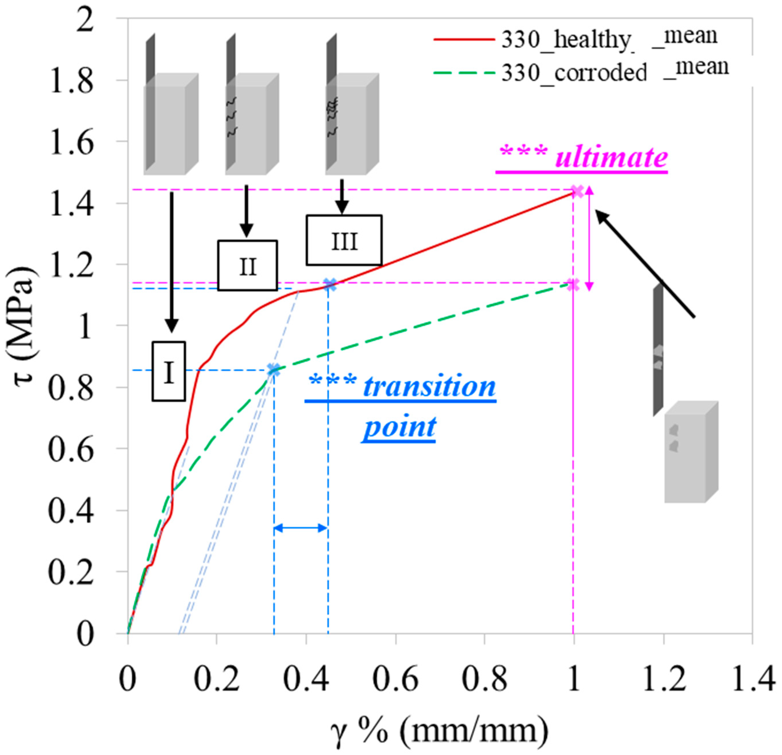
2.1. Capacity in Transferring Loads

The capacity of the strengthening system to transfer loads depends heavily on the type of FRP applied, the area in contact, and the connection layer (epoxy adhesive) as well as the initial structural integrity of the concrete substrate in which it will be embedded. Theoretically, the integration of the FRP system creates a monolithical cross-section in which the composite plays the role of the externally bonded reinforcement. However, due to the relative slip between the connected materials and the potential or progressive crack opening at the concrete substrate, this is not fully feasible [41]. Full integration would mean that the force is gradually transferred to the FRP on the whole with no abrupt failures or debonding of the elements of the system, e.g., concrete and adhesive layer, meaning that the cross-section would continue to bear stress and strains. A low integration level would denote that once the strengthening system starts bearing loads, debonding occurs. The integration level can also be reduced due to the existence of undesirable particles on the surface of the application of the retrofitting, even if properly cleaned according to technical specifications. This can be the result of pitting corrosion, for instance, in the case of accelerated corrosion or uniform distributed corrosion evident, especially if the retrofitting has been applied at the very early stages and products continue to leach [42].

2.2. Capacity of Limiting Failure Propagation

The failure propagation at the substrate level is crucial. The strain distribution and the crack opening create discontinuities and disruptions in the load path. As such, the crack propagation decreases the integration level and the monolithicity of the interface of the retrofitted cross-section. The type of FRP strengthening measure chosen indicates the development of different crack patterns under overloading conditions. For example, stiffer FRPs such as prefabricated plates, present a brittle debonding failure mode, whereas in FRP laminated sheets strengthening solutions, there are less abrupt force disruptions due to the crack propagation. This kind of crack and stress distribution along the interface vary also when different kinds of adhesives are used. Toughened adhesives that connect the composites and concrete absorb more energy since the cracks are re-directed when they encounter a rubber-like particle and propagate longer at the adhesive, enhancing the efficiency of the intervention.

2.3. Proposed Efficiency Indices

The privilege of the proposed index is mainly in involving the mechanical and geometric properties of the layers of the interface area created by the concrete substrate, the adhesive layer, and the FRP. It does not depend on the performance of the element at the ultimate stage and depicts the integration level even for service loads. The integration is indirectly understood by the quantification of the efficiency level and the corresponding failure mode as well as the type of FRP used.
For the proposed index, the quantification of the interface efficiency derives from (a) the capacity to transfer loads to the composite material and (b) the damage dislocation from the substrate (concrete) to the connection layer (epoxy adhesive). The expression of this quantification is the proposed Interface Capacity Index given by Equation (1):
I C = a · I C L + β · I C f p
The coefficients a and β represent the substrate’s initial condition: coefficient α equals 1 in cases where the integrity is not affected and corresponds to a fully healthy concrete element. The value can fall up to 0.8 when for e.g., corrosion has initiated and the products are obvious at the surface of the element. Coefficient β expresses the existence of initial cracks. The values of β range from 0.7–1. It is equivalent to 1 when the initial cracking is of limited width (w = 0–0.35 mm) whereas β can fall up to 0.7 in cases where the cracks’ width is larger than 1 mm.
The IC index is the sum of the two different factors, ICL for the interface capacity in transferring loads and ICfp for the interface capacity of damage dislocation. Both factors correlate the mechanical properties and thickness of the layers of the strengthening system, by considering the ratios of a macroscopic property over the mechanical one ( t r f r ,   t f f f ). This aspect ratio represents the abrupt changes due to cracking over the yield tensile strength of each layer along the bonded length Le transforming their relationship with the classification of the efficiency into a linear form. Whereas the aspect ratio of the moduli of elasticity of the adhesive layer and the FRP system ( E r E f ) shows the ability of the intermediate layer of the composite material and the substrate to deform. The higher this ratio is, the higher the cracking propagates to the adhesive, absorbing more energy. Equations (2) and (3) below summarize the above:
I C L = L e L · t r f r t f f f I C L = L e L · t r t f · f f f r
I C f p = E r E f · L e × W e d × L
The factor Le corresponds to the effective bond length of the composite material and is adopted according to the Eurocode 8 regulation [43] and is given by Equation (4):
L e = E f · t f 4 · f c t m
and We correspond to the active width of the composite and it is assumed to be decreased per 20% of the initial width. This decreased width represents the different manufacturing processes of the various FRP types and the corresponding response in energy release when the FRP itself starts developing fracture or when delamination begins [43,44]. In the above equations, tr and tf are the epoxy and composite’s thickness, fr and ff are the tensile strength, Er and Ef are the moduli of elasticity for the epoxy adhesive layer and the FRP, respectively, and lastly, fctm is the tensile strength of concrete. Finally, d corresponds to the height of the cross-section where the FRP is applied and L is the axial length of the element.

3. Experimental Campaign

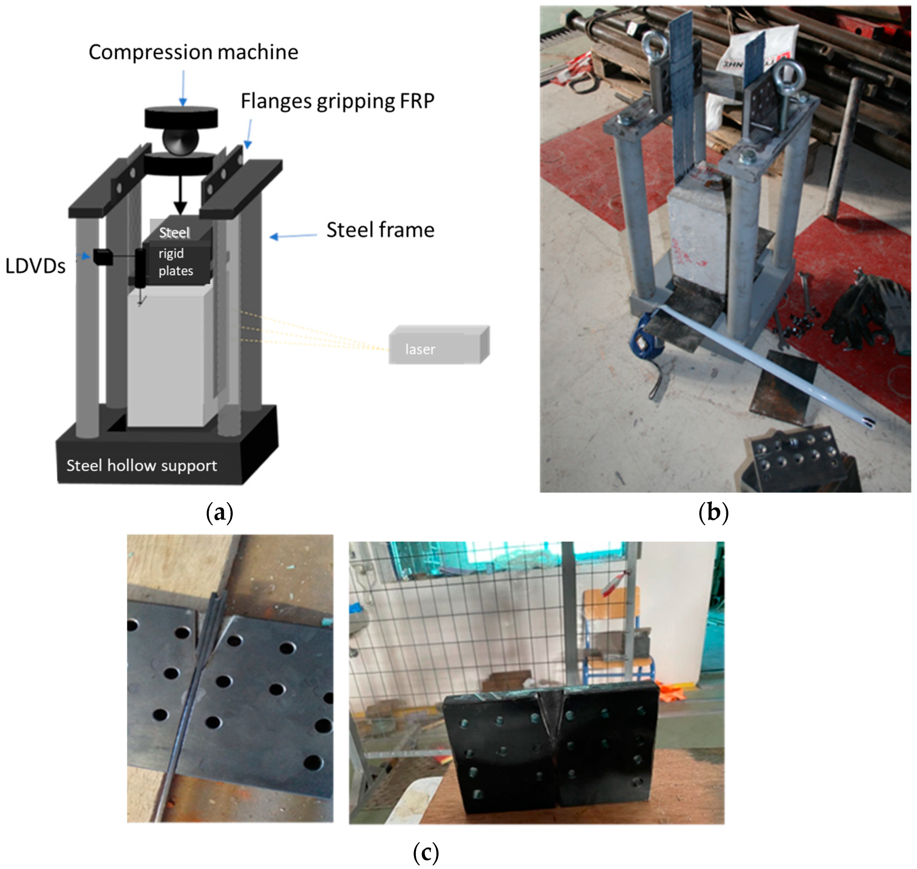
3.1. Double-Lap Shear Test Description

This study employs a modified double lap shear test configuration, as depicted in Figure 1. Unlike the conventional setup with two concrete blocks, our approach utilizes only one concrete block to which the FRPs are applied and securely fastened to the protruding end. The concrete block rests on a hollow support (Figure 1a), allowing for slip, and is suspended from the gripped ends of the FRPs attached to a sturdy steel frame (Figure 1b). The gripping steel plates were adapted with a wedge shape, as shown in Figure 1c, particularly for NSM bars. This modification minimizes relative slips, eliminates slips at the gripped ends, and facilitates direct shear stress measurement. The tests were conducted on a compression machine at a speed of 1 mm/min under room temperature conditions (20 °C). Deformation measurements of the central part of the CFRP at the central path (Figure 1a) were recorded using a high-precision laser sensor. Additionally, two Linear Displacement Transducers (LDVT) with a maximum capacity of 100 mm were employed to measure the displacement at the loading end of the concrete block and the grips.

3.2. Preparation of Specimens

3.2.1. Materials

This study comprises twenty-one concrete blocks, each measuring 150 × 150 × 250 mm, prepared in accordance with [44,45,46,47,48,49]. The concrete mix employed had a 28-day compressive strength of 37.5 MPa (CEMI, 42.5R, ω/c = 0.60), corresponding to a tensile strength of 3 MPa (Table 1). The choice of concrete mix aimed to ensure workability for prism casting and susceptibility to corrosion [50]. All blocks incorporated an 18 mm diameter steel rebar (500 MPa) placed longitudinally in the middle of the cross-section. Three distinct commercial CFRP strengthening schemes were selected (laminated sheets, prefabricated plates, and NSM). Laminated sheets and Near Surface Mounted bars exhibited higher tensile strength and modulus of elasticity compared to prefabricated plates, along with similar tensile strain (Table 2). All CFRPs were symmetrically bonded to opposite sides of the concrete blocks at a bond length of 200 mm using a dry lay-up process. Various bi-component epoxies curing at ambient temperature were employed for bonding, with Sikadur®-30 utilized for prefabricated plates and NSM bars (E = 9500 GPa, ε = 0.3%, Table 3) and Sikadur®-330 for laminated sheets, featuring the lowest modulus of elasticity and medium tensile strain. Additionally, all strengthening schemes were replicated using a newly available toughened epoxy adhesive (Sikadur®-370) with a modulus of elasticity equal to 5000 GPa and the highest tensile strain ε = 2.5%, specifically designed for the fatigue-resistant, long-lasting reinforcement of steel bridges [51].

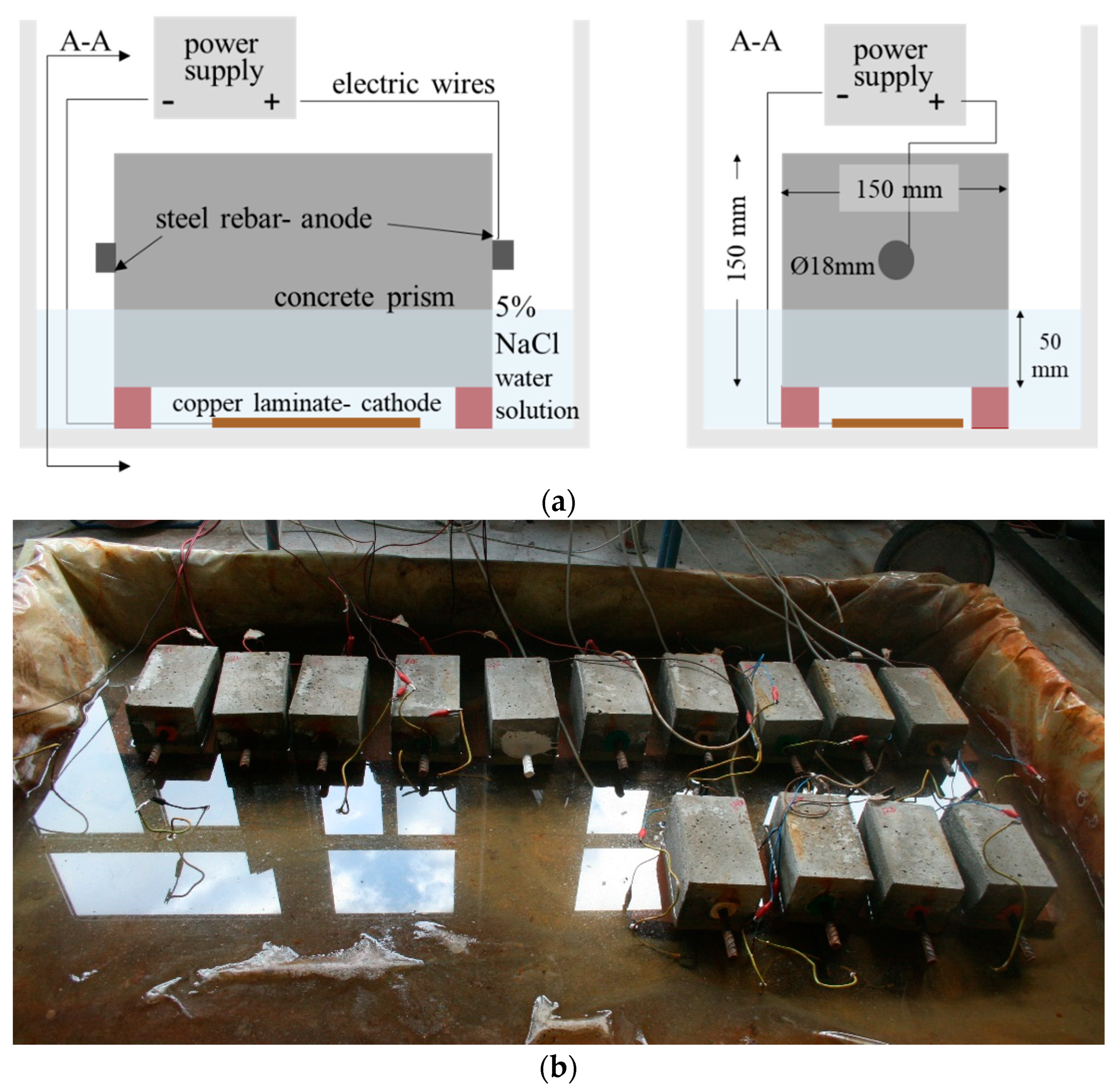
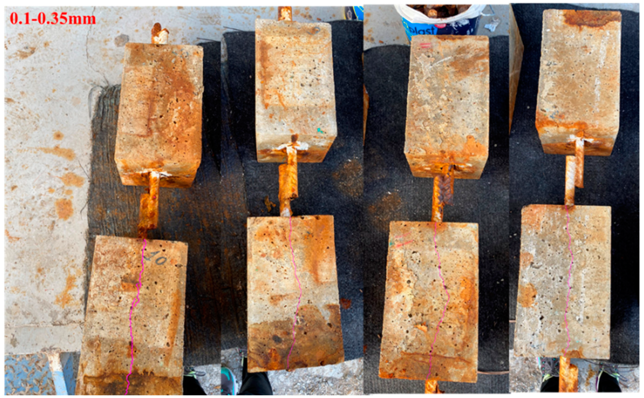
3.2.2. Accelerated Corrosion

Corrosion conditions are typically replicated in the laboratory using a NaCl solution and a controlled current flow in a tank. Nine concrete prisms underwent exposure to moist conditions in a specialized tank, immersed in a 3.5–5% weight NaCl-water solution (Figure 2a), covering one-third of the cross-sectional size of the concrete blocks [37,38,39]. To induce a corrosion ratio of approximately 6%, a continuous power supply (≈1 mA) was applied through wired steel rebars for about three weeks (Figure 2b). This led to crack openings in the concrete blocks (w = 0.1–0.35 mm) and a loss of rebar cross-section (approximately 0.4mm reduction in diameter), simulating conditions exceeding service limit states but not causing severe deterioration in ultimate limit states (Figure 3). Apart from the wet conditions, the samples were also exposed on-site in dry conditions before the application of the FRPs [39]. Subsequently, the tensile strength of concrete was evaluated through additional experiments drawn from international literature to avoid the need for patch repairs in the case of experimental measurements using pull-off tests [7,52,53].

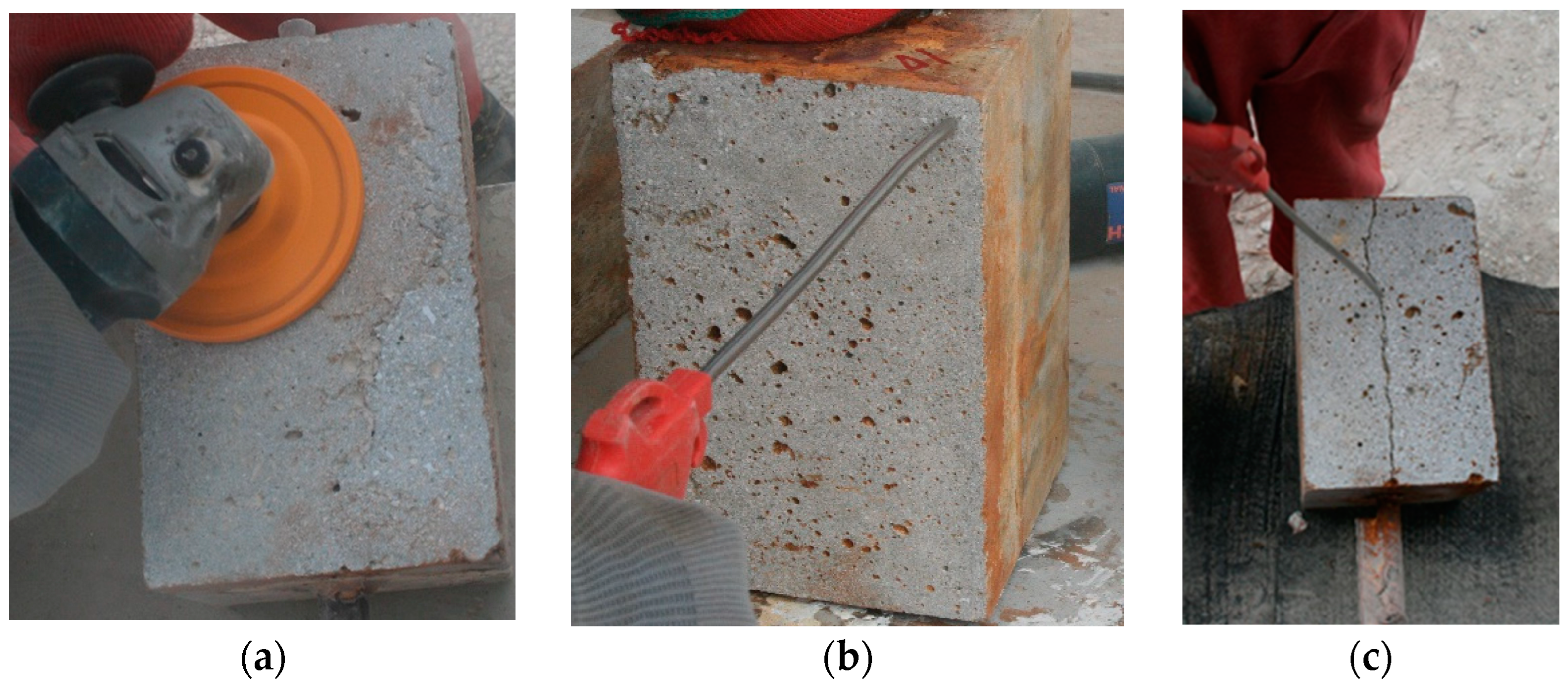
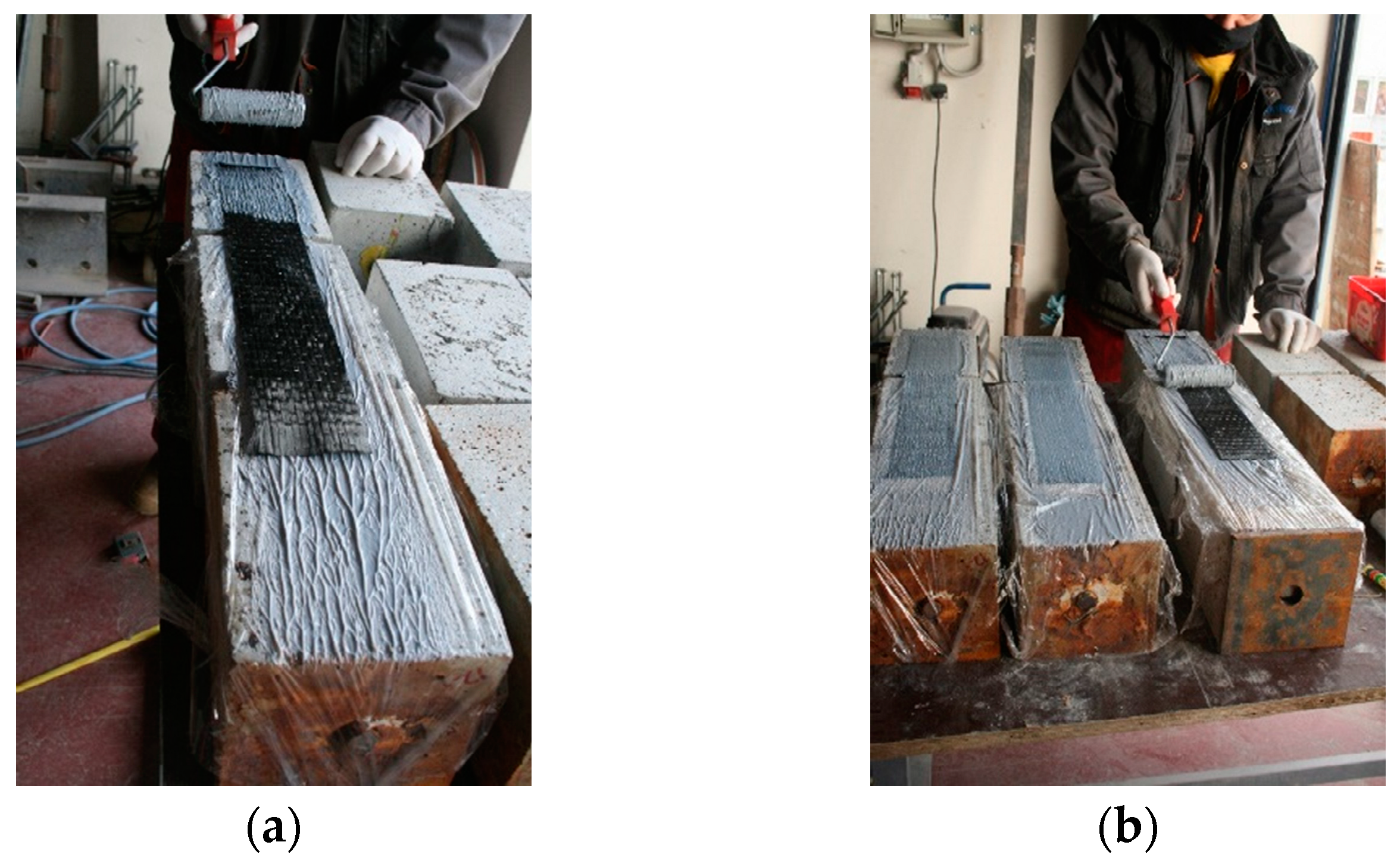
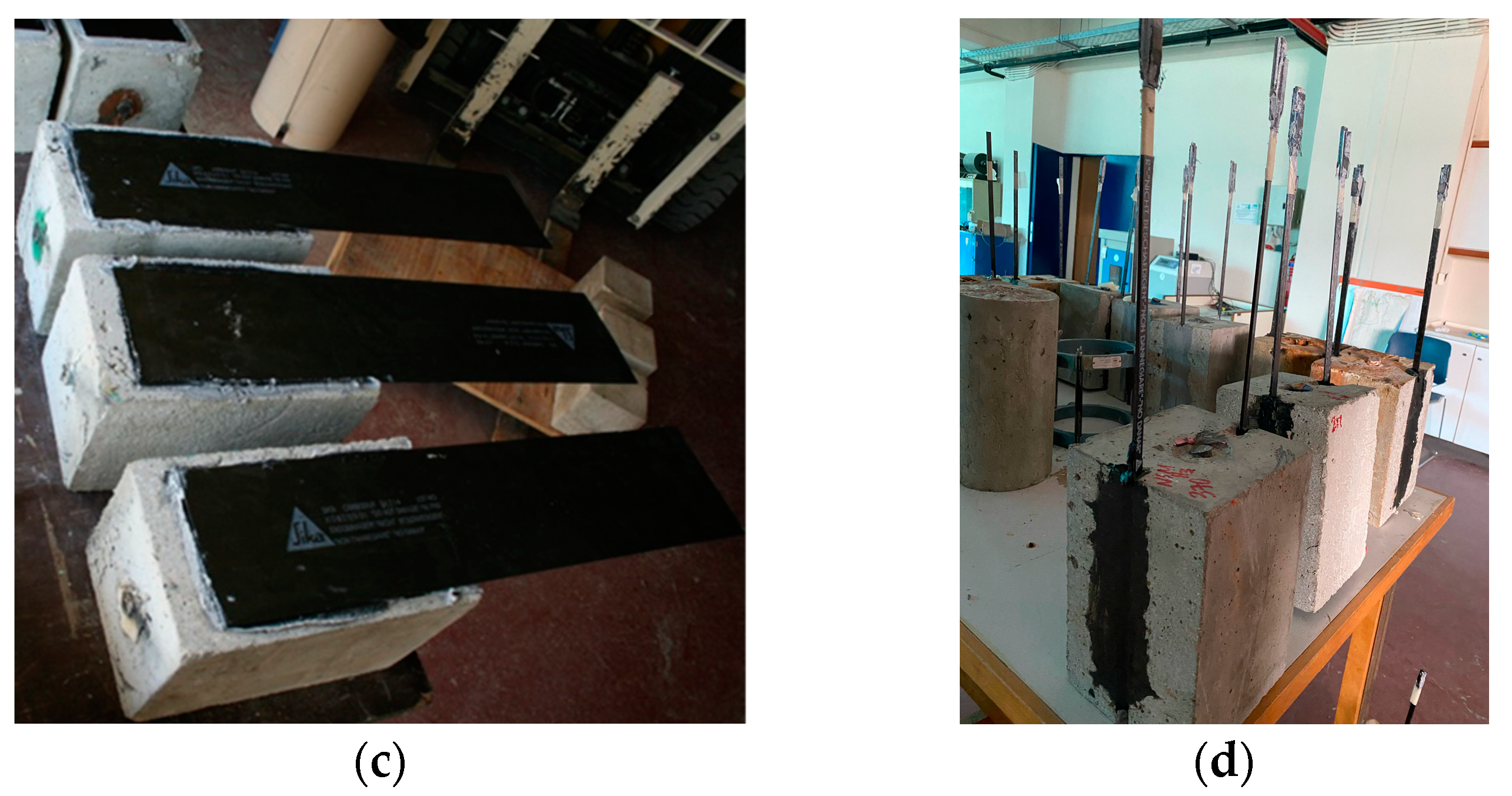
3.2.3. FRP Application

The composite strengthening systems were symmetrically bonded on opposite sides of the blocks with a bonding length of 200 mm on each side. For fabrics, the fiber orientation was set at 0° along the longitudinal direction of the concrete blocks. Pre-fabricated plates underwent cleaning with the specialized solvent-based cleaner Sika® Colma Cleaner, removing oil, grease, and dust at least 15 min before application. The systems were applied using a dry lay-up process, adhering to the technical specifications provided by the manufacturer. Proper treatment of the interfaces ensured a laitance contaminant-free, open-textured surface, cleaned with air pressure to eliminate loose material, dust, and rust (Figure 4). The two-component epoxy adhesives (Table 3) were mixed in accordance with the manufacturer’s recommended weight ratio and time (3:1 for Sikadur®-30, 4:1 for Sikadur®-330, and 100:74 for Sikadur®-370). The composites were left to cure under ambient conditions (20 °C, 50% relative humidity-RH) for at least a week before testing (Figure 5).

4. Results and Discussion

The experimental data of all tested specimens are summarized in Table 4. The same table also includes the data of the mean curve which represents the tendency of the specimens of each group during the shear test. The mean curve is presented in terms of shear stress τ (MPa) versus shear strain γ (%). The shear stresses are extracted by dividing the load by the interface area, whereas the shear strain is calculated by dividing the slip (s mm) by the adhesive layer thickness (tr in mm).

4.1. Experimental Results

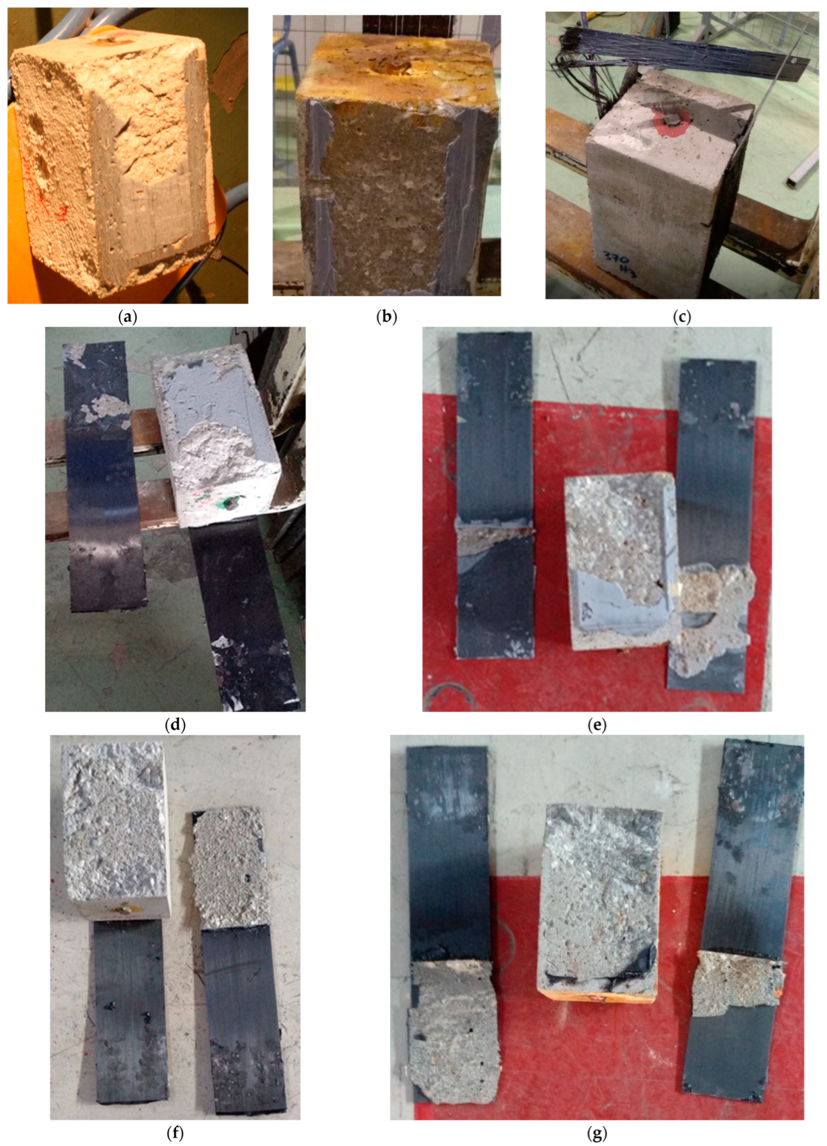
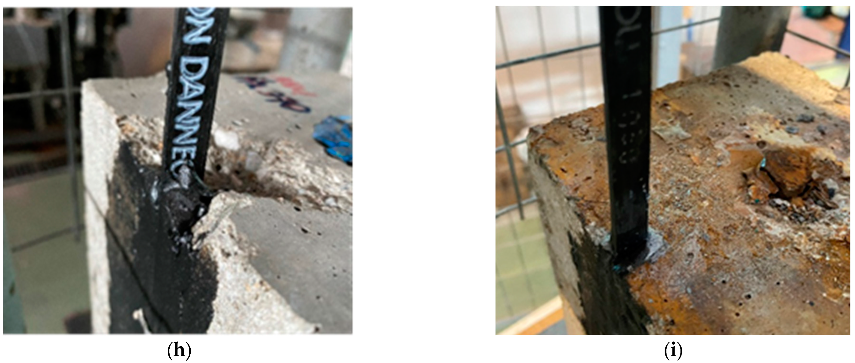
4.1.1. Failure Modes

The response as well as the failure mode of each group of specimens is mainly cohesive-adhesive and is shown in Figure 6. For the groups with laminated sheets, that is LSHl330x3, LSHl370x3, and LSCr330x3, the failure mechanism was progressive and resulted from the development of cracks on the concrete mass, followed by detachment of the applied composite sheet after it was tensed [54], regardless of the existence of corrosion products. Due to the consistency of the laminated sheets (carbon), the elongation is not measurable, and as such it is not considered in the following analysis. FRP rupture is met in only one case, where the epoxy’s ultimate strain is considerably larger than that of the FRP (LSHl370_3, Figure 7c) but generally, the dominant failure is mainly adhesive-cohesive. This case only accounted for when a toughened adhesive was used to bond the laminated sheets (εs = 2.5%). Based on that fact, as well as on the adhesion failure mode depicted in Figure 6, a clear impact of the toughness of the adhesive is recognized. Due to the induced toughness, the stress on the bonded material is divided on larger surfaces. The rubber particles cavitate and trigger shear deformation in the matrix or the epoxy [55,56,57], resulting in substrate failure as shown in Figure 6f,g. Whereas, the use of usual high mechanical brittle adhesive layers, leads to a more adhesive failure, induced by high peek stresses at the boarders of the composites (see Figure 6a,b,d,e). This progressive failure mode is also noted in the response curve. The substrate crack propagation to the adhesive layer is indicated by the transition points [58] after which detachment occurs gradually (Figure 7). The transition points practically correspond to the strengthening system’s propagating failure and progressive delamination up to debonding. The failure mode of the prefabricated plates, that is PPHl30x3, PPCr30x3, PPHl370x3, and PPCr370x3, was also of adhesion-cohesion type. All the specimens exhibited brittle failure with the plate being debonded from the concrete. (Figure 6d–g). For the NSM groups adhesively bonded with Sikadur®-370, the failure differs. At the end of the tests, the failure observed was associated with the concrete local plastification. An adhesive to concrete interface failure was noted, and practically the NSM bar pulled out of the concrete mass followed by a breakout cone (Figure 6h,i). This variation is related to the actual embedment of the NSM bars to the concrete substrate and the smaller the area of the interface. The results are presented in shear stress, shear deformation diagrams of the mean curves for the different categories of specimens (Figure 8). Also, the mean error is noted (Table 4).

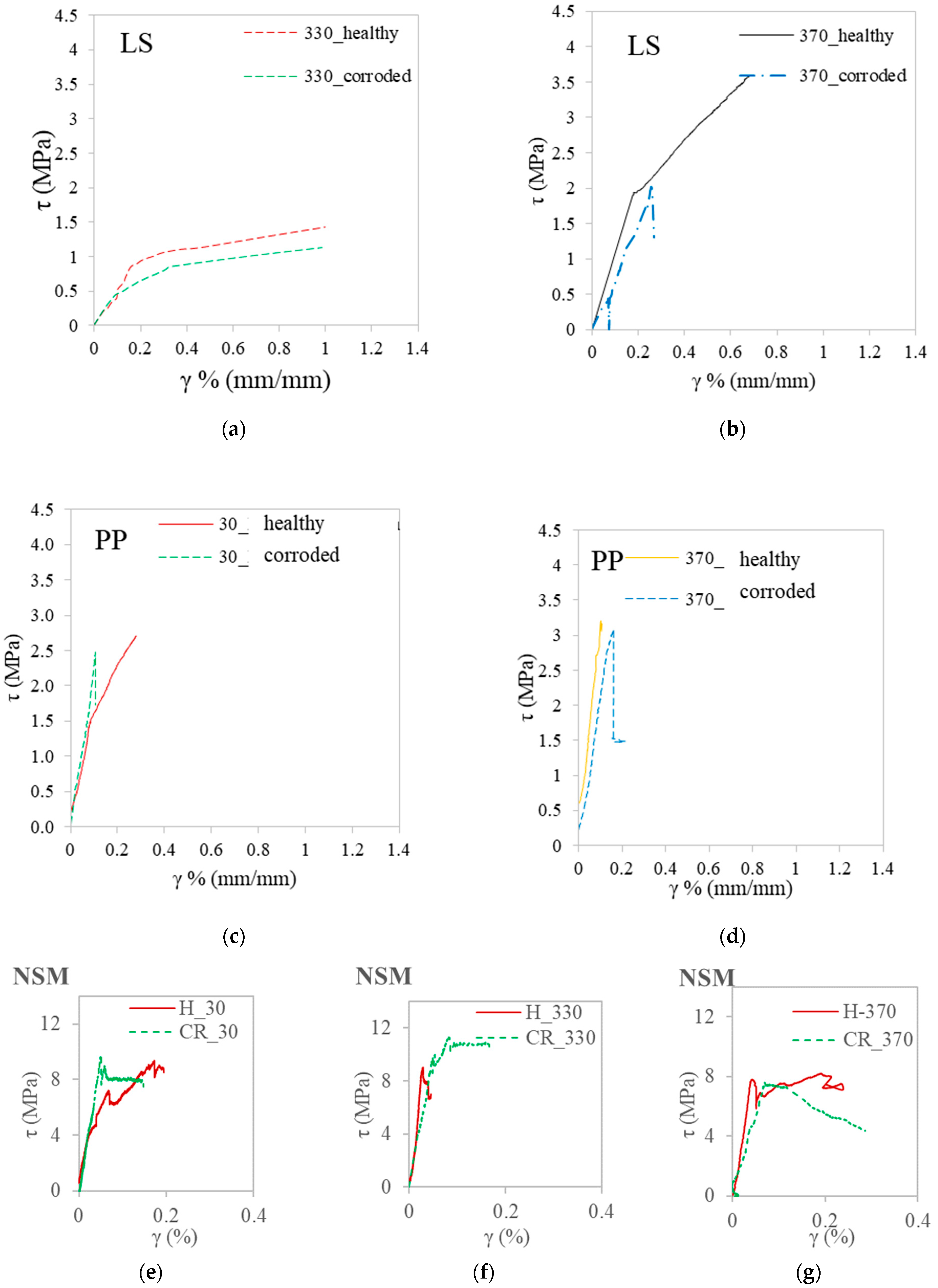
4.1.2. FRP Laminated Sheets

Samples with incorporated laminated sheets (LSHl330x3, LSCr330x3), consisting of unidirectional carbon fibers bonded with the epoxy adhesive layer Sikadur®-330, demonstrate a response having three discernible stages, illustrated in Figure 7. The adhesive layer plays an important role in constraining the spread of substrate failure, facilitating fracture progression in incremental stages, and absorbing greater energy before debonding. The epoxy layer’s reduced elasticity, combined with an elevated strain limit, enhances its capacity to absorb more energy before reaching the point of debonding.
In the first stage (Stage I: linear elastic), the sheets experience linear tension, with fibers parallel to the loading direction preventing bridging at the crack initiation. The second stage involves progressive crack opening of the epoxy layer, leading to a non-linear elastic yielding branch up to the transition point (Stage II: non-linear elastic yielding). The transition point (τtrans, γtrans) corresponds to further crack propagation at the adhesive and substrate, disturbing the bonding of the two materials. The third stage is marked by significant cracking in both the adhesive layer and the substrate, creating local failure of concrete, particularly at the initial debonding area which is considered 5 cm from the loading end. At the ultimate point of this stage (Stage III: major cracking), specimens exhibit FRP debonding (τu, γu), primarily caused by adhesion loss in the delamination area, with no FRP rupture (Figure 8a).
The mean curve of specimens with corroded steel rebar (green dashed line) and laminated sheets applied to the concrete substrate with epoxy adhesive layer Sikadur®-330, and the average curve of healthy specimens with the same epoxy (red solid line) is plotted in Figure 8. There is a significant differentiation between the two cases, with the interface of the substrate with corrosion products (LS_330_corroded) exhibiting a 20% decrease in shear strength (τu) and a 24% lower shear deformation (γu) at the ultimate point (Table 4). The transition point is noticed to lower values of deformations (52%) and strength (18%). The leached corrosion products on the sides of the concrete prisms, coupled with minor strains due to corrosion initiation create inconsistency, reducing resistance. Even in these early stages of corrosion, corresponding to corrosion initiation and allowable bond values of the substrate for immediate interventions, concrete crack and rust, weaken the bond strength, resulting in a lower slip and shear strength regime.
A matrix with 25% higher stiffness presents a different response (LSHl370x3, Table 4). This group of specimens, with laminated sheets bonded with the epoxy adhesive layer Sikadur®-370, exhibits a clear brittle behavior. As illustrated in Figure 8a, the intrinsic toughness of the matrix enhances the substrate’s capacity to bear shear stresses, presenting an anelastic response. The transition point in this case is decreased by 80% compared to the corresponding case with the Sikadur®-330 layer. This denotes that the failure propagation of the substrate begins at different stress rates. Although there is a similar bond response, the shear stresses are 70% higher at the transition point and 2.5 times higher at the ultimate stage. The crack pattern in the adhesive layer propagates simultaneously up to the debonding point of the strengthening system. The toughened adhesive layer Sikadur®-370 is designed for steel substrates and is focused on fatigue cracking applications. The width of cracks in concrete substrates exceeds that observed in fatigue cracking of steel substrates. In combination with the stiffness of the adhesive and the presence of rubber-like particles, the response, permitting the redirection of cracking and the failure mode, alters from adhesive-cohesive to FRP rupture (Figure 8c). The absorbed energy is 15% higher in such cases.

4.1.3. FRP Prefabricated Plates

For the case of specimens with prefabricated plates bonded with different adhesive layers there is a significant increase in the initial stiffness equal to 10%. The shear deformations range in comparatively lower (50–85%) values with respect to the group bonded with laminated sheets. The failure mode is similar for all groups. The delamination is abrupt at the ultimate point and ends in a brittle debonding mechanism. The fundamental difference between the prefabricated plates and the laminated sheets is the much higher stiffness and mechanical properties. The strengthening in that case is much stronger and the response of the CRP type is dominant and governs the failure mode. The contribution of the different adhesives is minor, mainly noticeable to weaker strengthening schemes, such as laminated sheets.
Specimens with plates bonded externally with the standard adhesive Sikadur®-30 present a bilinear response. In Figure 8b, the two distinct stages are exhibited. There is a clear transition point between the two stages, yet the second branch is quite abrupt. Analogously to the wrapped specimens, the transition point denotes the propagating delamination and crack opening.
The group with the Sikadur®-370 epoxy adhesive layer (Figure 8b, yellow line PP_370_healthy) presents a shifted behavior in cases of the prefabricated plates, especially if compared to the results of the Sikadur®-30 adhesive layer. As noted in specimens with laminated sheets, also in the case of plates, the stages are compressed and the response is mainly elastic. Failure happens in lower stress values (12%) and in remarkably lower values of shear deformations, reaching up to 24% decrease. The CFRP prefabricated plates strengthening measure has no capacity to bridge the crack opening of both the epoxy and the substrate, and therefore the debonding is ‘premature’. Practically, the toughened layer eliminates the crack opening at the substrate level and the integrity of concrete remains unchanged, even after premature debonding, absorbing almost 25% of the energy, achieving the energy rates of delaminated plates from literature regardless of their type of delamination [45]. The structural member remains without further damage and needs minor if any, repair before re-strengthening or other kinds of intervention.
Regarding the effect of the integrity of the substrate on the bond-slip behavior of the strengthening scheme, there is a strong impact due to the existence of the corrosion products at the connected interfaces. Both in terms of strains and stresses, there is a remarkable decrease in shear deformation up to 47% for the ultimate point. In all cases, the stages are compacted and the stress rates are similar. In this group, the early corrosion level effect is minor for both applications of adhesive layers. For the case of Sikadur®-30 epoxy, debonding happens in 10% lower values of shear strains as summarised also in Table 4. Whereas for the toughened layer the response is similar.

4.1.4. FRP near Surface Mounted Bars

Likewise, the NSM groups exhibited a consistent pattern. The pattern is characterized by an initial linear response leading up to the peak point, followed by a non-linear behavior with a sudden decrease and finally a sustained load. The peak point corresponds to the ultimate strain limit of the adhesives and coincides with the transition point. The observed slip of the bar is attributed to the mechanical interlock of materials at the interface.
For the healthy concrete substrate (Figure 6e–g), it was evident that all adhesives exhibited nearly identical stress levels with minor variations ranging up to 15%. The strain levels were similar between the conventional Sikadur®-30 and the toughened Sikadur®370 adhesive in the ultimate level, despite the significant difference in their modulus of elasticity. Compared with Sikadur®-330, having intermediate-level mechanical properties, the performance of the toughened layer was also better, particularly in terms of strain levels before reaching the point of pull-out. Sikadur®-370 exhibited an early transition point, indicating its activation and strain-bearing capacity before complete loss of bond and slip due to material interlocking at the interface. The toughened epoxy absorbed a high percentage of energy before failure as high as the compatible Sikadur®-30 before the concrete cone detached from the prism. In comparison to Sikadur®-330, the toughened epoxy absorbed nearly 70% more energy, while remaining on a similar level to Sikadur®-30 epoxy in terms of the remaining stress level.
For the corroded substrates, the compatible adhesives Sikadur®-330 and Sikadur®-370 displayed a slightly different response when compared to the healthy specimens. For these cases (Figure 6e–g), both adhesives exhibited a reduced (5%) initial stiffness and distinct stress-strain characteristics. Specifically, Sikadur®-330 displayed similar stresses in the presence of substrate corrosion and up to 55% lower strain levels. In contrast, the intermediate adhesive layer Sikadur®-330 maintained stress capacity under both substrate conditions. The response of the toughened adhesive Sikadur®-370 was slightly influenced by the presence of corrosion products, and the curve exhibited less steepness after the peak point (Figure 8g), indicating a different crack propagation scheme on the substrate before pull-out. In terms of energy absorption, NSM bars embedded with the toughened epoxy Sikadur®-370 exhibited higher energy absorption than all adhesives.

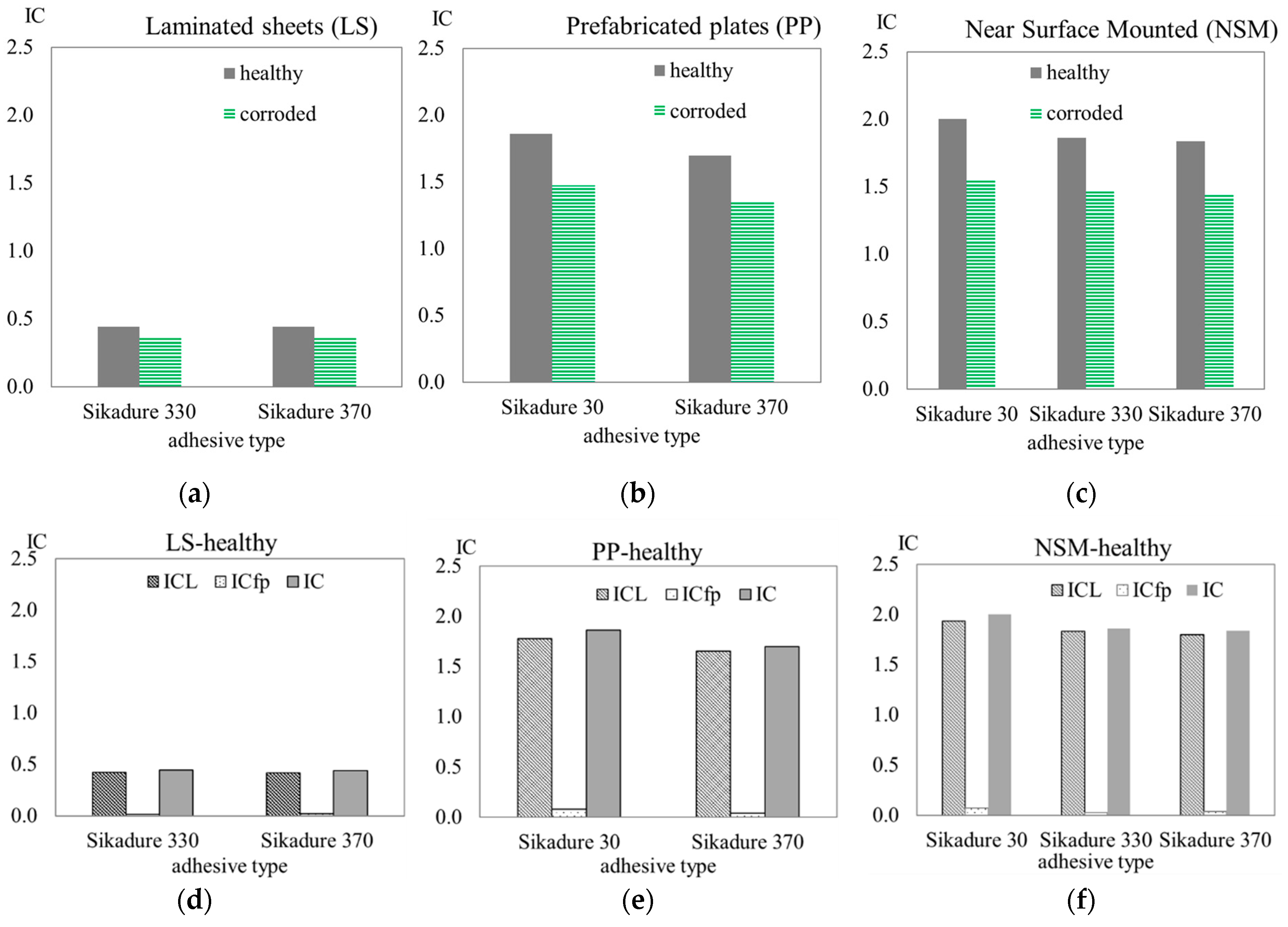
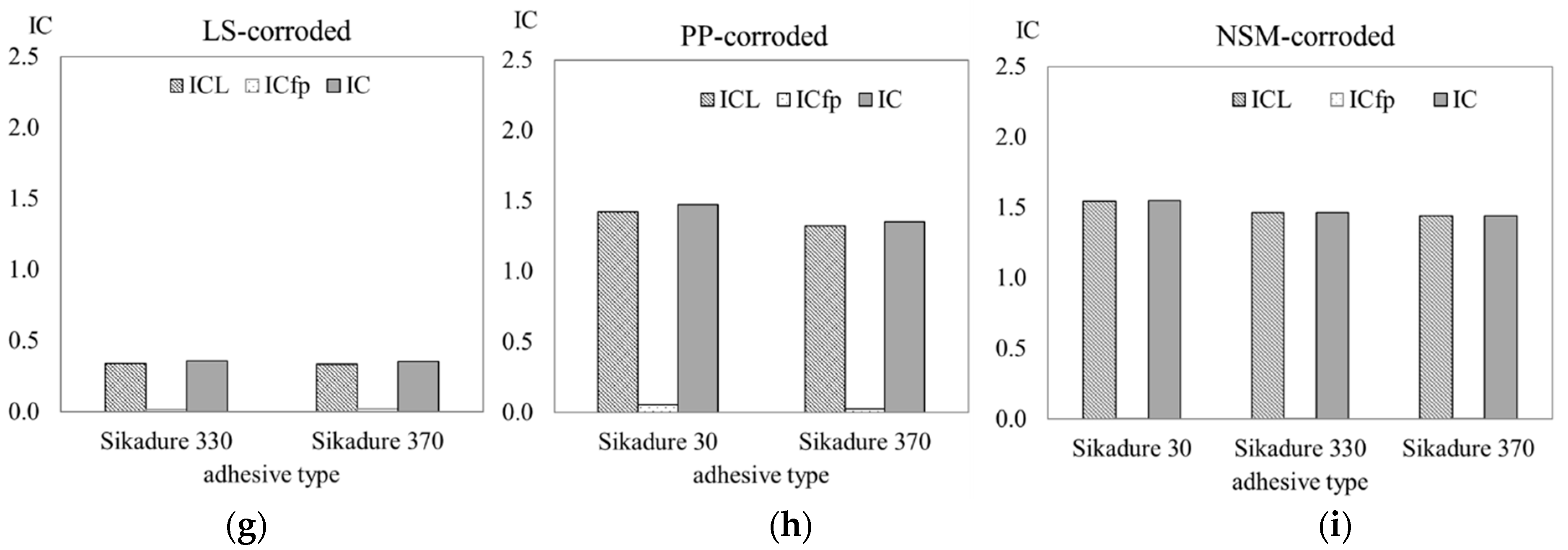
4.1.5. Interface Capacity (IC) Indices Estimation

According to the equations of Section 2.3 above, the Interface Capacity (IC) indices for all groups of specimens of the experimental campaign are calculated (Table 5) and are illustrated in the bar chart in Figure 9. The group of specimens with the NSM bars embedded present higher values of the index, both for healthy substrates as well as for the case of corrosion (Figure 9a). The IC index is up to 8% higher for the same epoxy adhesive (Sikadur®-370) with respect to the prisms with prefabricated plates (Figure 9b). Each group presents indices of the same magnitude and corresponds to a different type of performance as well as failure.
The IC index represents the overall capacity of the interface to bear stresses and strains and is the sum of the two individuals, ICL and ICfp, as discussed previously. The higher the Index ICL is the more the FRP measure is activated. The ratio t r f r t f f f shows how the failure is shaped over the bonded length. For higher values, the interface transfers forces in a uniform way. The failure is not abrupt yet the adhesive type and the concrete substrates need further repair. Regarding the values of the index ICfp, they denote the failure type, which is debonding most likely for high values or pull-out in the case of NSM. The premature failure in such a case due to the absorption of energy from the substrate leads to an untouched substrate with no further damages and a fully reversible retrofitting. Yet it is different in the cases of embedded NSM bars since the concrete absorbs energy leading to a conical failure at the loading end. For the case of laminated sheets (LS), for both adhesives, the indices are identical (Figure 9a) and for the case of prefabricated plates (PP), the values are higher (Figure 9b) and slightly higher for the case of NSM (Figure 9c). This is due to the type of application of the different composites. The impregnation of the adhesives to the laminated sheets as well as the deformability of the sheets themselves change completely the response if compared to the prefabricated plates (PP) or the NSM. The interface contribution in those two cases is completely different. The capacity indices illustrated in Figure 9d–f denote the contribution of the adhesive to the overall capacity of the interface (ICfp). For the prefabricated plate type, the ICfp index is four times higher from the laminated sheets, whereas on the whole, the IC is significantly lower οn the laminated sheets. The toughened epoxy capacity (ICfp) in this case (PP) is lower (50%) and the overall capacity is decreased too (IC 8–10% lower). This variation confirms that a strengthening measure can be equally efficient by using adhesive layers of reduced stiffness. The charts of Figure 9h–g also demonstrates the effect of the presence of corrosion products on the substrate. There is a clear reduction in the IC metrics of the same magnitude for the different CFRP cases, with the maximum value equal to 25% for the NSM bars.

5. Conclusions

The work presented in this paper includes a series of experimental results collected by the testing of concrete prisms with externally adhesively bonded FRPs in a double-lap setup. Different types of FRPs were applied with standard and toughened epoxies, and applied in healthy or concrete surfaces with corrosion products. The main conclusions of this research are summarized in the following points:
  • The quantification of the interface capacity is expressed with a semi-empirical expression with the IC index and is based on two criteria: (a) loads transferred to the composite through the interface and (b) strains and crack propagation up to failure. FRP integration is enhanced when the index is larger. A value of IC lower than one means the response is linearly elastic and the failure is brittle. The greater the value is the more distinct the transition points are and the crack propagation is extended.
  • CFRP strengthening schemes for concrete substrates with toughened adhesive layers with lower stiffness matrix exhibit more abrupt failures, achieving higher stresses. The overall interface capacity in distributing cracks and loads is similar in sheets and plates, whereas in the NSMs case is more concentrated. The dispersion of stresses when using toughened adhesives should be further investigated in larger areas of substrates.
  • The type of CFRP plays an important role in the response of the interface. The direction of the fibers of the composite can bridge the gaps from the crack development. The different composite types in combination with the adhesive layer can permit strain distribution in a more extended area. Prefabricated plates have much higher stiffness and mechanical properties with respect to laminated sheets and govern the failure mode.
  • The corrosion effect is more evident in the group with externally bonded laminated sheets, where a reduction of 20% is noted both in shear resistance and deformation. The effective length of the strengthening system should be considered increased in such cases, in order to have the adhesive properties of the matrix fully developed.
  • The failure mode is predominantly cohesive adhesive. The induced toughened epoxies absorb more energy and distribute stresses/strains in the matrix in contrast to the usual high mechanical brittle adhesive layers that lead to adhesive failure with peek stresses concentrated at the borders of the composites.
  • Strengthening adhesives do not necessarily need high values of mechanical prop-erties. Toughened epoxy adhesives introduce moderately reduced stiffness (47–57%) for bonding FRPs still ensuring high strengthening performance for concrete retrofitting cases, and absorb more energy and strains as such the substrate’s fail-ure propagation is less significant.
  • The corrosion of the substrates affected mainly the conventional epoxies schemes that is Sikadur®-30 and Sikadur®-330. These adhesives are characterized by lower strain capacity and mainly high elastic modulus, especially Sikadur®-30 having the highest elastic modulus. The influence of the toughened epoxy Sikadur®-370 was not significant. The fact that the substrate’s corrosion does not affect the system which still deforms and continues to absorb energy can be beneficial to structural applications.
Based on the above results and conclusions, more research is needed with intermediate epoxies properties to validate the model (semi-empirical) for the quantification of IC and provide values of indexes with interpolation for any kind of epoxy adhesive layer-composite combination.

Author Contributions

Conceptualization, D.V.A.; methodology, D.V.A.; software, D.V.A. and N.K.S.; validation, D.V.A., A.K. and N.K.S.; formal analysis, D.V.A. and A.K.; investigation, D.V.A., A.M. and F.C.; resources, D.V.A., A.M. and F.C.; data curation, D.V.A., A.K. and N.K.S.; writing—original draft preparation, D.V.A. and A.K.; writing—review and editing, D.V.A., A.M. and F.C.; visualization, D.V.A. and A.K.; supervision, D.V.A.; project administration, D.V.A.; funding acquisition, D.V.A. All authors have read and agreed to the published version of the manuscript.

Funding

This study has received funding by the European Commission H2020-Marie Skłodowska-Curie Research Grants Scheme MSCA-IF-2018 (grant agreement no 845549: BRIFACE- Novel assessment of bridge retrofitting measures through Interface Efficiency Indices (InterFeis) using a Guided Wave-based monitoring method).

Data Availability Statement

The original contributions presented in the study are included in the article, further inquiries can be directed to the corresponding authors.

Acknowledgments

Authors warmly thank the industrial partner, SIKA AG. for offering consultancy and materials. We thank Sika Hellas for the support in the application of the composites. Finally, special thanks to the Reinforced Concrete and Seismic Design Laboratory of Democritus University of Thrace for collaborating on the experimental campaign.

Conflicts of Interest

Author Antonino Montalbano was employed by the company Sika Services AG; Author Fabien Choffat was employed by the company Sika Technology AG. The remaining authors declare that the research was conducted in the absence of any commercial or financial relationships that could be construed as a potential conflict of interest.

References

  1. Abbood, I.S.; aldeen Odaa, S.; Hasan, K.F.; Jasim, M.A. Properties evaluation of fiber reinforced polymers and their constituent materials used in structures–A review. Mater. Today Proc. 2021, 43, 1003–1008. [Google Scholar] [CrossRef]
  2. Al-Fasih, M.Y.; Mohamad, M.E.; Ibrahim, I.S.; Ahmad, Y.; Ariffin, M.M.; Sarbini, N.N.; Mohamed, R.N.; Kueh, A.B.H. Experimental and numerical evaluations of composite concrete-to-concrete interfacial shear strength under horizontal and normal stresses. PLoS ONE 2021, 16, e0252050. [Google Scholar] [CrossRef] [PubMed]
  3. Naser, M.Z.; Hawileh, R.A.; Abdalla, J.A. Fiber-reinforced polymer composites in strengthening reinforced concrete structures: A critical review. Eng. Struct. 2019, 198, 109542. [Google Scholar] [CrossRef]
  4. Hegde, S.; Shenoy, B.S.; Chethan, K.N. Review on carbon fiber reinforced polymer (CFRP) and their mechanical performance. Mater. Today Proc. 2019, 19, 658–662. [Google Scholar] [CrossRef]
  5. EN1504-4:2004; Products and Systems for the Protection and Repair of Concrete Structures—Definitions, Requirements, Quality Control and Evaluation of Conformity—Part 4: Structural Bonding, European Committee for Standardization. British Standards Institution: London, UK, 1998.
  6. Zhang, Y.; Su, R.K.L. Concrete cover tensile capacity of corroded reinforced concrete. Constr. Build. Mater. 2017, 136, 57–64. [Google Scholar] [CrossRef]
  7. Triantafyllou, G.G.; Rousakis, T.C.; Karabinis, A.I. Analytical assessment of the bearing capacity of RC beams with corroded steel bars beyond concrete cover cracking. Compos. Part B Eng. 2017, 119, 132–140. [Google Scholar] [CrossRef]
  8. Pereira, E.N.B.; Fischer, G.; Barros, J.A.; Lepech, M. Crack Formation and Tensile Stress-Crack Opening Behavior of Fiber Reinforced Cementitious Composites (FRCC). In Proceedings of the FraMCoS-7, Jeju, Republic of Korea, 23–28 May 2010. [Google Scholar]
  9. De Oliveira e Sousa, J.L.A.; Gettu, R. Determining the tensile stress-crack opening curve of concrete by inverse analysis. J. Eng. Mech. 2006, 132, 141–148. [Google Scholar] [CrossRef]
  10. Fazli, H.; Yassin, A.M.; Shafiq, N.; Teo, W. Pull-off testing as an interfacial bond strength assessment of CFRP-concrete interface exposed to a marine environment. Int. J. Adhes. Adhes. 2018, 84, 335–342. [Google Scholar] [CrossRef]
  11. Batuwitage, C.; Fawzia, S.; Thambiratnam, D.; Al-Mahaidi, R. Durability of CFRP strengthened steel plate double-strap joints in accelerated corrosion environments. Compos. Struct. 2017, 160, 1287–1298. [Google Scholar] [CrossRef]
  12. Garbacz, A.; Piotrowski, T.; Courard, L.; Kwaśniewski, L. On the evaluation of interface quality in concrete repair system by means of impact-echo signal analysis. Constr. Build. Mater. 2017, 134, 311–323. [Google Scholar] [CrossRef]
  13. Attard, T.L. Toughened carbon-fiber reinforced epoxy via isophorone diisocyanate amine surface modification. Polymer 2020, 191, 122268. [Google Scholar] [CrossRef]
  14. Burchardt, B.; Schulenburg, J.O.; Linnenbrink, M. Neue Technologiebausteine für den Leichtbau. adhäsion Kleb. Dicht. 2009, 53, 42–47. (In German) [Google Scholar] [CrossRef]
  15. Kasper, Y.; Albiez, M.; Ummenhofer, T.; Mayer, C.; Meier, T.; Choffat, F.; Ciupack, Y.; Pasternak, H. Application of toughened epoxy-adhesives for strengthening of fatigue-damaged steel structures. Constr. Build. Mater. 2021, 275, 121579. [Google Scholar] [CrossRef]
  16. Kasper, Y.; Albiez, M.; Ummenhofer, T.; Ciupack, Y.; Ledecky, L.; Pasternak, H.; Geßler, A.; Feldmann, M. Application of carbon fibre composite materials for the rehabilitation of fatigue damaged steel structures. In Advances in Engineering Materials, Structures and Systems: Innovations; Zingoni, A., Ed.; Mechanics and Applications; CRC Press: Boca Raton, FL, USA, 2019; pp. 2148–2153. [Google Scholar]
  17. Feldmann, M.; Ummenhofer, T.; Geßler, A.; Pasternak, H.; Kasper, Y.; Albiez, M.; Ciupack, Y.; Ledecky, L. Einsatz geklebter CFK-Lamellen zur Verstärkung ermüdungsgeschädigter Stahlkonstruktionen. Fachbeitrag. Geklebte Cfk-Lamellen Schweißen Schneid. 2019, 71, 738–745. (In German) [Google Scholar]
  18. Achillopoulou, D.V. Investigation of the bond behaviour of interfaces of CFRP sheet strengthening schemes enhanced with toughened epoxy adhesive layers in corroded concrete substrates. In Proceedings of the 8th International Conference on Computational Methods in Structural Dynamics and Earthquake Engineering COMPDYN 2021, Athens, Greece, 27–30 June 2021. [Google Scholar]
  19. Promis, G.; Ferrier, E. Performance indices to assess the efficiency of external FRP retrofitting of reinforced concrete short columns for seismic strengthening. Constr. Build. Mater. 2012, 26, 32–40. [Google Scholar] [CrossRef]
  20. Park, Y.J.; Ang, A.H.S. Mechanistic seismic damage model for reinforced concrete. J. Struct. Eng. 1985, 111, 722–739. [Google Scholar] [CrossRef]
  21. CNR-DT 200/2004; Advisory Committee on Technical recommendations For Constructions. Guide for the Design and Construction of Externally Bonded FRP Systems for Strengthening Existing Structures. National Research Council: Rome, Italy, 2004; pp. 62–68; 131–132.
  22. Achillopoulou, D.V.; Rousakis, T.C.; Karabinis, A.I. Square reinforced concrete columns strengthened through fiber reinforced polymer (FRP) sheet straps. In Proceedings of the 6th International Conference on FRP Composites in Civil Engineering (CICE 2012), Rome, Italy, 13–15 June 2012; pp. 13–15. [Google Scholar]
  23. Nisticò, N.; Pallini, F.; Rousakis, T.; Wu, Y.F.; Karabinis, A. Peak strength and ultimate strain prediction for FRP confined square and circular concrete sections. Compos. Part B Eng. 2014, 67, 543–554. [Google Scholar] [CrossRef]
  24. Ascione, F.; Napoli, A.; Realfonzo, R. Interface bond between FRP systems and substrate: Analytical modeling. Compos. Struct. 2021, 257, 112942. [Google Scholar] [CrossRef]
  25. Yuan, C.; Chen, W.; Pham, T.M.; Hao, H. Bond behavior between basalt fibres reinforced polymer sheets and steel fibres reinforced concrete. Eng. Struct. 2018, 176, 812–824. [Google Scholar] [CrossRef]
  26. Jia, D.G.; Gao, W.Y.; Duan, D.X.; Yang, J.; Dai, J.G. Full-range behavior of FRP-to-concrete bonded joints subjected to combined effects of loading and temperature variation. Eng. Fract. Mech. 2021, 254, 107928. [Google Scholar] [CrossRef]
  27. Min, X.; Zhang, J.; Wang, C.; Song, S.; Yang, D. Experimental investigation of fatigue debonding growth in FRP–concrete interface. Materials 2020, 13, 1459. [Google Scholar] [CrossRef] [PubMed]
  28. Jiang, C.; Wan, B.; Wu, Y.F.; Omboko, J. Epoxy interlocking: A novel approach to enhance FRP-to-concrete bond behavior. Constr. Build. Mater. 2018, 193, 643–653. [Google Scholar] [CrossRef]
  29. Mensah, C.; Wang, Z.; Bonsu, A.O.; Liang, W. Effect of different bond parameters on the mechanical properties of FRP and concrete interface. Polymers 2020, 12, 2466. [Google Scholar] [CrossRef] [PubMed]
  30. Zhang, P.; Lei, D.; Ren, Q.; He, J.; Shen, H.; Yang, Z. Experimental and numerical investigation of debonding process of the FRP plate-concrete interface. Constr. Build. Mater. 2020, 235, 117457. [Google Scholar] [CrossRef]
  31. Wang, Y.; Zhu, X.; Hao, H.; Ou, J. Guided wave propagation and spectral element method for debonding damage assessment in RC structures. J. Sound Vib. 2009, 324, 751–772. [Google Scholar] [CrossRef]
  32. Mukhtar, F.M.; Faysal, R.M. A review of test methods for studying the FRP-concrete interfacial bond behavior. Constr. Build. Mater. 2018, 169, 877–887. [Google Scholar] [CrossRef]
  33. Hallonet, A.; Michel, L.; Ferrier, E. Investigation of the bond behavior of flax FRP strengthened RC structures through double lap shear testing. Composites Part B Eng. 2016, 100, 247–256. [Google Scholar] [CrossRef]
  34. Rotunno, T.; Rovero, L.; Tonietti, U.; Bati, S.B. Experimental study of bond behavior of CFRP-to-brick joints. J. Compos. Constr. 2015, 19, 04014063. [Google Scholar] [CrossRef]
  35. Aboubakret, S.H.; Kandil, U.F.; Taha, M.R. Creep of epoxy–clay nanocomposite adhesive at the FRP interface: A multi-scale investigation. Int. J. Adhes. Adhes. 2014, 54, 1–12. [Google Scholar] [CrossRef]
  36. Sneed, L.H.; D’Antino, T.O.M.M.A.S.O.; Carloni, C.; Pellegrino, C. A comparison of the bond behavior of PBO-FRCM composites determined by double-lap and single-lap shear tests. Cem. Concr. Compos. 2015, 64, 37–48. [Google Scholar] [CrossRef]
  37. Van Zijl, G.P.; Paul, S.C. A novel link of the time scale in accelerated chloride-induced corrosion test in reinforced SHCC. Constr. Build. Mater. 2018, 167, 15–19. [Google Scholar] [CrossRef]
  38. Dodds, W.; Christodoulou, C.; Goodier, C.; Austin, S.; Dunne, D. Durability performance of sustainable structural concrete: Effect of coarse crushed concrete aggregate on rapid chloride migration and accelerated corrosion. Constr. Build. Mater. 2017, 155, 511–521. [Google Scholar] [CrossRef]
  39. Otieno, M.; Beushausen, H.; Alexander, M. Chloride-induced corrosion of steel in cracked concrete–Part I: Experimental studies under accelerated and natural marine environments. Cem. Concr. Res. 2016, 79, 373–385. [Google Scholar] [CrossRef]
  40. Kim, T.K.; Park, J.S. Evaluation of the Performance and Ductility Index of Concrete Structures Using Advanced Composite Material Strengthening Methods. Polymers 2021, 13, 4239. [Google Scholar] [CrossRef]
  41. Brozović, T.; Kišiček, T.; Mandić Ivanković, A. Static and dynamic response of damaged prestressed RC beams flexural strengthened with CFRP. In Proceedings of the 12th Central European Congress on Concrete Engineering Innovative Materials and Technologies for Concrete Structures, Tokaj, Hungary, 31 August–1 September 2017; p. 659. [Google Scholar]
  42. Ming, J.; Shi, J. Distribution of corrosion products at the steel-concrete interface: Influence of mill scale properties, reinforcing steel type and corrosion inducing method. Constr. Build. Mater. 2019, 229, 116854. [Google Scholar] [CrossRef]
  43. EN 1998-3; Eurocode 8: Design of Structures for Earthquake Resistance—Part 3: Assessment and Retrofitting of Buildings. European Committee for Standardisation: Brussels, Belgium, 2009.
  44. Kazemi, M.E.; Medeau, V.; Mencattelli, L.; Greenhalgh, E.; Robinson, P.; Finlayson, J.; Pinho, S.T. Novel zone-based hybrid laminate structures for high-velocity impact (HVI) in carbon fibre-reinforced polymer (CFRP) composites. Compos. Sci. Technol. 2023, 241, 110148. [Google Scholar] [CrossRef]
  45. Kuhtz, M.; Hornig, A.; Gude, M.; Jäger, H. A method to control delaminations in composites for adjusted energy dissipation characteristics. Mater. Des. 2017, 123, 103–111. [Google Scholar]
  46. EN 206-1; Concrete—Part 1: Specification, Performance, Production and Conformity. CEN: London, UK, 2000.
  47. EN 197-1-2011; Cement-Part 1: Composition, Specifications and Conformity Criteria for Common Cements. CEN: London, UK, 2000.
  48. ACI 318-1; Building Code Requirements for Reinforced Concrete. ACI: Farmington Hills, MI, USA, 2011.
  49. Kosmatka, S.H.; Wilson, M.L. Design and Control of Concrete Mixtures: The Guide to Applications, Methods, and Materials, 15th ed.; Portland Cement Association: Washington, DC, USA, 2021. [Google Scholar]
  50. Sumanth, H.B.; Vasugi, K. Effect of w/c ratio on the corrosion of rebar embedded in high strength concrete. J. Of. Corros. Sci. Eng. 2020, 23, Preprint 12. [Google Scholar]
  51. Sika Group. Pioneering Steel Bridge Repair: Sikadur®-370. Sika Innovation. Available online: https://www.sika.com/en/innovation/sika-innovation-flash/pioneering-steel-bridge-repair--sikadur--370.html (accessed on 15 June 2023).
  52. EN 1542; Products and Systems for the Protection and Repair of Concrete Structures-Test Methods-Measurement of Bond Strength by Pull-Off. British Standard Institution: London, UK, 1999.
  53. Courard, L.; Piotrowski, T.; Garbacz, A. Near-to-surface properties affecting bond strength in concrete repair. Cem. Concr. Compos. 2014, 46, 73–80. [Google Scholar] [CrossRef]
  54. Biscaia, H.C.; Micaelo, R.; Chastre, C. Cyclic performance of adhesively bonded joints using the Distinct Element Method: Damage and parametric analysis. Compos. Part B Eng. 2019, 178, 107468. [Google Scholar] [CrossRef]
  55. Sue, H.J.; Garcia-Meitin, E.I.; Pickelman, D.M. Fracture behavior of rubber-modified high-performance epoxies. In Polymer Toughening; CRC Press: Boca Raton, FL, USA, 2020; pp. 131–174. [Google Scholar]
  56. Leelachai, K.; Kongkachuichay, P.; Dittanet, P. Toughening of epoxy hybrid nanocomposites modified with silica nanoparticles and epoxidized natural rubber. J. Polym. Res. 2017, 24, 41. [Google Scholar] [CrossRef]
  57. Bagheri, R.; Marouf, B.T.; Pearson, R.A. Rubber-toughened epoxies: A critical review. J. Macromol. Sci. Part C Polym. Rev. 2009, 49, 201–225. [Google Scholar] [CrossRef]
  58. De Santis, S.; Carozzi, F.G.; de Felice, G.; Poggi, C. Test methods for textile reinforced mortar systems. Compos. Part B Eng. 2017, 127, 121–132. [Google Scholar] [CrossRef]
Figure 1. Experimental setup: (a) sketch, (b) steel frame, (c) gripping ends.
Constrmater 04 00010 g001
Figure 2. Accelerated corrosion (a) schematic map and (b) curing specimens in the tank (wet conditions).
Constrmater 04 00010 g002
Figure 3. Corroded substrates: crack pattern and opening range.
Constrmater 04 00010 g003
Figure 4. Interface treatment: (a) smoothing the surface using a grinding wheel with diamond cutters (b) surface and (c) crack cleaning by high-pressured air.
Constrmater 04 00010 g004
Figure 5. Application of FRPs and curing: (a) applying primer and application of the fabric, (b) impregnation of epoxy layer following the fibers’ direction, (c) prefabricated plates, and (d) NSM integration.
Constrmater 04 00010 g005aConstrmater 04 00010 g005b
Figure 6. Failure modes of the groups of specimens: (ac) laminated sheets, (dg) prefabricated plates, and (h,i) NSM bars. (a) adhesive applied onto healthy substrate- Sikadur®-330; (b) adhesive applied onto substrate with corrosion products- Sikadur®-330; (c) adhesive applied onto healthy substrate- Sikadur®-370; (d) adhesive applied onto healthy substrate- Sikadur®-30; (e) adhesive applied onto substrate with corrosion products using Sikadur®-30; (f) adhesive applied onto healthy substrate- Sikadur®-370; and (g) adhesive applied onto substrate with corrosion products using Sikadur®-370.
Constrmater 04 00010 g006aConstrmater 04 00010 g006b
Figure 7. Mean shear stress-strain experimental curves for specimens with laminated sheets.
Constrmater 04 00010 g007
Figure 8. Mean curves of shear stress-strain experimental results for prisms of healthy or corroded substrate externally bonded with laminated sheets-LS: (a) standard epoxy and (b) toughened adhesive, with prefabricated plates-PP: (c) standard adhesive and (d) toughened adhesive and containing NSM bars (e,f) standard adhesives and (g) toughened adhesive.
Constrmater 04 00010 g008
Figure 9. Interface Capacity (IC) indices vs adhesive type bar chart: (a,d,g) laminate sheets-LS, (b,e,h) prefabricated plates (PP) and NSM (c,f,i).
Constrmater 04 00010 g009aConstrmater 04 00010 g009b
Table 1. Composition of the concrete mixture.
Aggregate Coarse
MaterialCement
CEM I (42.5R)
Natural SandCrushed SandMediumLargeWater
quantity (kgr/m3)310621351236638191
Table 2. Mechanical properties of CFRPs.
TypeDensity ρ [kg/L]TensileE-ModulusTensile Strain ε (EAB) [%]
Strength σu [MPa](0.05–0.25%) [GPa]
Prefabricated plates1.631001701.8
Carbodur S
Fabrics1.849002301.7
SikaWrap
NSM bars1.631001701.8
Sika® CarboDur® S
Table 3. Mechanical properties of epoxy adhesives.
TypeDensity ρ [kg/L]Tensile Strength σu [MPa]E-Modulus
(0.05–0.25%) [MPa]
Tensile Strain ε (EAB) [%]
Sikadur®-30~22695000.3
Sikadur®-330~1.42940001
Sikadur®-370~1.73050002.5
Table 4. Experimental results.
Healthy Substrate With Corroded Products
τtrans τu γtrans γu E τtrans τu γtrans γu E
(MPa)(MPa)(%)(%)(MJ/m3) (MPa)(MPa)(%)(%)(MJ/m3)
Laminated sheetsHl330_11.251.480.721.331.56Cr330_10.941.110.471.731.59
Hl330_21.281.380.571.461.76Cr330_20.991.20.320.60.51
Hl330_30.821.370.60.910.84Cr330_30.831.090.120.470.39
mean 3301.121.410.631.231.39average 3300.921.130.30.930.83
Hl370_11.973.580.20.671.7Cr370_10.951.80.090.220.26
Hl370_21.83.570.120.631.59Cr370_21.32.20.140.250.37
Hl370_31.943.560.070.651.73Cr370_31.22.10.180.280.38
mean 3701.93.570.170.651.63average 3701.152.030.140.250.34
abs error 370-33041%61%263%90%15%abs error 370-33020%44%122%273%147%
Prefabricated platesHl30_11.502.550.110.731.42Cr30_1-3.00-0.130.20
Hl30_21.922.380.110.140.28Cr30_2-2.50-0.190.24
Hl30_31.803.520.110.601.50Cr30_3-2.10-0.050.05
mean 301.742.820.110.491.06average 30-2.53-0.120.15
Hl370_1-3.50-0.090.16Cr370_1-3.05-0.120.18
Hl370_2-3.17-0.110.17Cr370_2-2.90-0.210.30
Hl370_3-2.80-0.120.17Cr370_3-3.35-0.140.24
mean 370-3.16-0.110.17average 370-3.10-0.160.25
abs error 370-30-0.10-0.750.84abs error 370-30-0.02-0.470.40
NSM barsHl30_112.1012.050.060.211.85Cr30_112.329.250.060.251.96
Hl30_29.2310.910.050.272.64Cr30_27.998.470.040.150.94
Hl30_310.0710.020.080.262.04Cr30_3
mean 307.85 9.20 0.08 0.22 2.18 mean 30 9.85 8.0 0.05 0.20 1.45
Hl330_112.369.290.040.080.70Cr330_110.3810.100.050.161.36
Hl330_213.109.800.050.090.62Cr330_210.1510.250.040.171.38
Hl330_39.287.760.050.110.57Cr330_36.8510.100.060.211.61
mean 3309.1 6.9 0.04 0.08 0.63 mean 330 10.05 10.95 0.08 0.18 1.45
Hl370_112.349.200.040.251.92Cr370_113.139.380.070.251.99
Hl370_28.069.830.030.272.12Cr370_211.228.910.060.151.05
Hl370_36.699.050.030.201.41Cr370_37.299.860.060.271.94
mean 3707.95 7.85 0.05 0.25 1.81 mean 370 7.85 7.75 0.07 0.15 1.66
abs error 370-30 0.013 0.15 0.50 0.12 0.17 abs error 370-30 0.2 0.031 0.29 0.25 0.13
abs error 370-330 0.13 0.12 0.2 0.68 0.65 abs error 370-330 0.22 0.29 0.13 0.17 0.13
Table 5. Interface Efficiency Indices.
HealthyCorroded
ICLICfpICE (MJ/m3)ICLICfpICE (MJ/m3)
Laminated Sikadur® 3300.430.020.441.390.340.020.360.83
sheetsSikadur® 3700.420.020.441.630.340.020.360.34
Prefabricated Sikadur® 301.780.081.861.0610.051.480.15
platesSikadur® 3701.660.041.700.171.320.031.350.25
NSMSikadur® 301.930.072.002.181.550.001.551.45
barsSikadur® 3301.830.031.860.631.460.001.471.45
Sikadur® 3701.800.041.841.811.440.001.441.66
Disclaimer/Publisher’s Note: The statements, opinions and data contained in all publications are solely those of the individual author(s) and contributor(s) and not of MDPI and/or the editor(s). MDPI and/or the editor(s) disclaim responsibility for any injury to people or property resulting from any ideas, methods, instructions or products referred to in the content.

