Article

A Decommissioned Wind Blade as a Second-Life Construction Material for a Transmission Pole

1
School of Civil and Environmental Engineering, Georgia Institute of Technology, Atlanta, GA 30332, USA
2
School of Architecture, Georgia Institute of Technology, Atlanta, GA 30332, USA
3
Department of Civil Engineering and Construction, Georgia Southern University, Statesboro, GA 30460, USA
*
Author to whom correspondence should be addressed.
Constr. Mater. 2021, 1(2), 95-104; https://doi.org/10.3390/constrmater1020007
Submission received: 29 April 2021 / Revised: 21 June 2021 / Accepted: 1 July 2021 / Published: 7 July 2021

Abstract

:
This paper demonstrates the concept of adaptive repurposing of a portion of a decommissioned Clipper C96 wind turbine blade as a pole in a power transmission line application. The current research program is aimed at creating a path towards sustainable repurposing of wind turbine blades after they are removed from service. The present work includes modelling and analysis of expected load cases as prescribed in ASCE 74 and NESC using simplified boundary conditions for tangent pole applications. Load cases involving extreme wind, concurrent ice and wind, extreme ice, differential ice, broken conductor, and broken shield have been analyzed and governing load cases for bending, shear, and torsion have been examined. Relative stiffnesses of different parts forming the wind blade’s cross section (i.e., shell, web, and spar cap) are determined. The corresponding stresses associated with each part under the governing loads are compared to allowable strength values which are determined from composite laminate theory and modelling of the known laminate structure of the E-Glass FRP material. Stresses and deflections obtained are compared with governing reliability-based design criteria and code requirements. The results of the structural analysis indicate that the wind blade can resist the expected loads with reasonable safety factors and that the expected deflections are within permissible limits. Recommendations are provided for detailing and modification of the wind blade for a power pole application in which crossarm and davit connections are highlighted, and foundation details are emphasized.

1. Introduction

The wind turbine industry is expected to stockpile millions of tons of composite wind blades in the coming years [1]. These structures are mainly manufactured from E-Glass fiber (with some use of Carbon fiber) embedded in epoxy, polyester, or vinyl ester resins [2]. The service life of a wind turbine blade is typically 20–25 years. However, many blades are coming out of service prior to that due to repowering (i.e., using larger wind blades to increase power generation of the turbine). The strength and stiffness of the composites in a wind blade degrade due to the in-service fatigue loading as the rotor rotates; however, this has been shown to be in the range of only 10–20% [3,4,5]. For second-life applications, this decrease in mechanical properties can be accounted for in the design process, especially when the blades are subjected to quasi-static loads. In addition, the need for environmentally responsible behavior is driving wind farm owners and turbine OEMs (original equipment manufacturer) to look for sustainable repurposing of wind blades in new structural applications (see for example www.re-wind.info (accessed on 6 July 2021)) [6,7,8]. Other small, medium, and large-scale structural reuse applications have also been described by Joustra et al. [9,10], André et al. [11], and Jensen and Skelton [12].
The power transmission industry has seen the introduction of fiber-reinforced polymer (FRP) poles in recent years. These poles have exceptional durability [13,14] and are expected to last longer than conventional steel, concrete, or timber poles. Based on the proven track record of existing FRP poles with wind turbine blades that are made using the same glass fiber reinforced composite materials, a new pole configuration has been proposed [15,16].
The current work presents a structural configuration of a decommissioned Clipper C96 blade used as a power transmission pole. The name BladePole is used by the authors to describe wind blades repurposed as transmission or distribution utility poles. In the current configuration the wind blade is used as a tangent pole; however, configurations as dead-end poles and corner poles are also possible in design. Structural analyses for different load cases are performed and the resulting stresses are compared to allowable strength values. Material partial safety factors, overdesign factors, and safety factors are determined to evaluate the feasibility of the proposed structure.

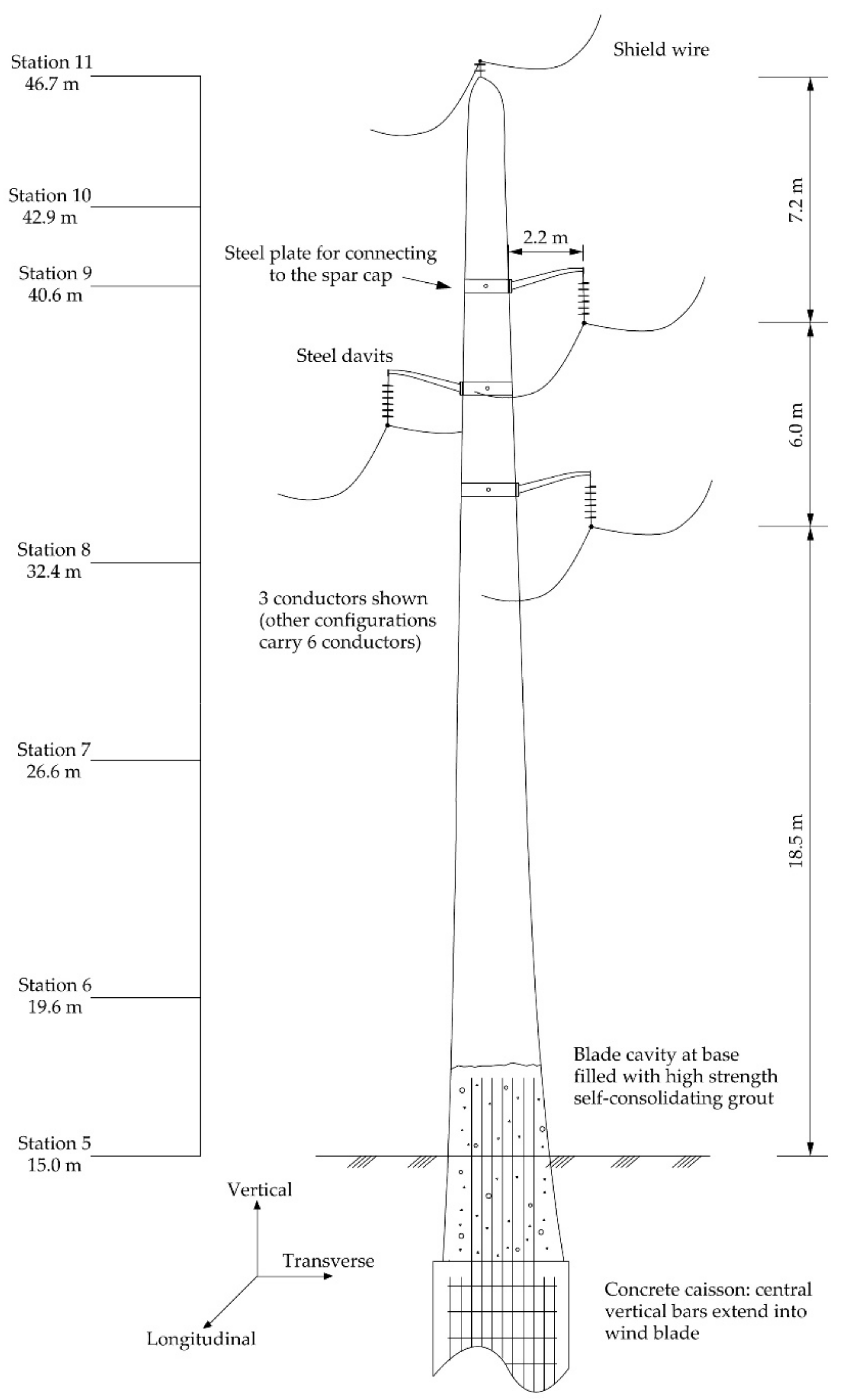
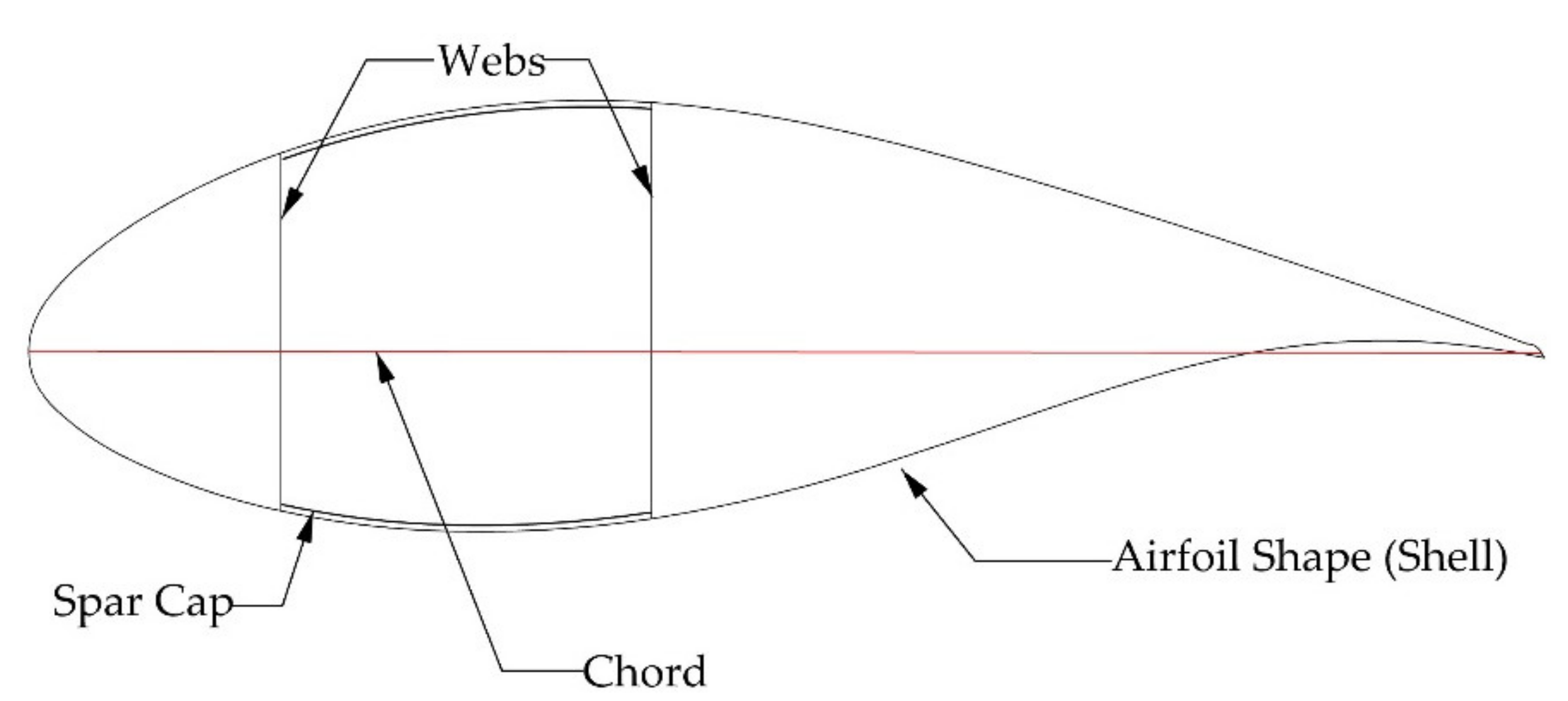
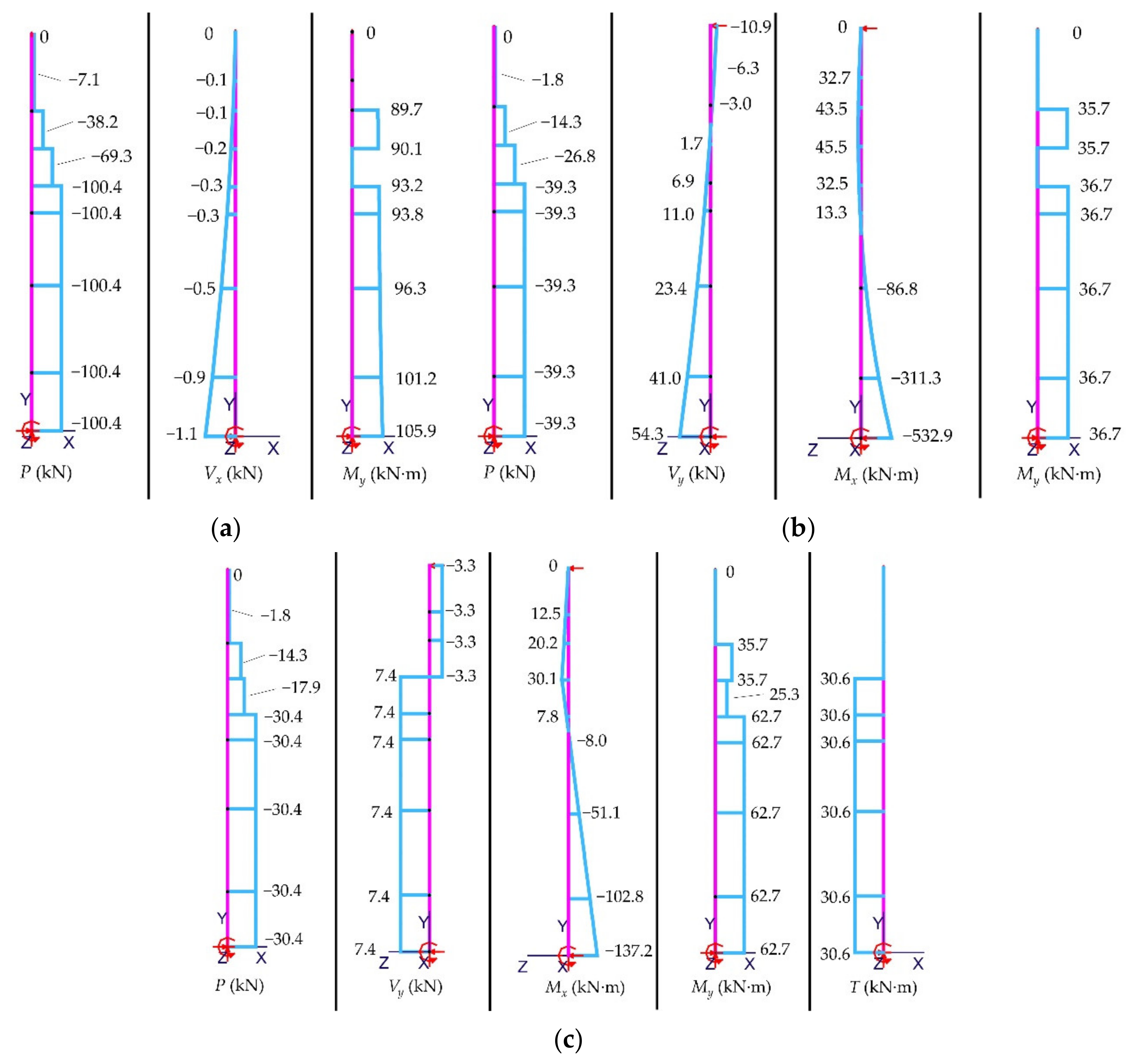
2. BladePole Configuration, Modelling and Analysis

There are hundreds of configurations for power transmission poles that are currently used in the power transmission field [17]. Depending on the voltage that the system carries, various requirements need to be met for the design. The main requirements include horizontal clearances from the structure, vertical clearances from one phase to the other, phase swing clearances, and vertical clearances from the conductors to physical obstacles underneath them. The configuration provided in Figure 1 shows these clearances for a Clipper C96 blade used as a BladePole carrying 230 kV conductors [18]. Figure 2 shows a typical cross-section of the wind blade. The stations shown in the figure with their corresponding cross-sections, dimensions, and structural properties and analysis are presented elsewhere [15,16]. Steel davits are connected to the body of the BladePole with steel connector plates conforming to the blade’s surface. The steel connector plates are bolted to the spar cap material (the structural carrying part of the cross-section of a wind blade). In addition to the spar cap, there are two other parts in any blade’s cross-section: the shell (the airfoil shape), and the webs (supports the cross-section against shear and buckling) as shown in Figure 2. Note that the proposed configuration has three conductors (i.e., single circuit); however, if six conductors are used (i.e., double circuit), symmetry and low bending forces result, and higher safety factors may be obtained. The current configuration and loads are different from what has been presented in Alshannaq et al. [16] which was intended for 69 kV or 138 kV capacities. The current design is intended for a 230 kV capacity with greater distance between the poles.
Structural analysis of the BladePole was performed using 1-D beam elements under first-order linear analysis mode. The pole was assumed to be fixed at the base, free at the top in the transverse direction, and pin-supported by the shield wire in the longitudinal direction. Note that this modelling assumption did not consider the conductors’ additional restraining effect in the longitudinal direction (further finite element analysis will be conducted to account for all restraining effects from all elements). Mastan2 was used to conduct the analysis [19]; however, any software program that deals with irregular shapes (airfoil shapes of wind blades) with user-defined cross-sectional properties can be used.
The load cases used to verify structural adequacy of any power transmission pole include extreme wind, extreme ice, combined wind and ice, differential ice, broken shield wire(s), and broken conductor(s). Several variants of the same load case (e.g., wind direction in 45° increments) resulted in a larger number of cases and only the most critical cases are presented here. Several regional loads are defined in ASCE-74 [20] and NESC [21]. The critical load cases used in the analysis presented are extreme wind of 144.8 km/hr. (90 mph), extreme ice of 25.4 mm (1 in.), combined ice of 19.1 mm (¾ in.) and wind of 48.3 km/hr. (30 mph), differential ice of 25.4 mm (1 in.) on one side and 12.7 mm (½ in.) on the other side.
Load case 1 represents concurrent wind (in the transverse direction) and ice, load case 2 represents extreme wind (in the longitudinal direction), and load case 3 represents a broken conductor (the single conductor on the left of the BladePole in Figure 1). Load case 1 and load case 2 result in the largest axial stresses in the structure, load case 2 results in the largest shear stresses from shear forces, while load case 3 results in the largest shear stresses from torsional forces.
The axial, shear, and moment diagrams resulting from the structural analysis are shown in Figure 3 for load case 1 (Figure 3a), load case 2 (Figure 3b) and load case 3 (Figure 3c). These diagrams were used to calculate axial and shear stresses at different locations along the BladePole.
Stress calculations were performed using a mechanics of materials approach that included orthotropic materials and irregular cross-sectional shapes [22,23]. For further details on the stress calculations, see Alshannaq et al. [16]. Figure 4 shows the stresses resulting from the diagrams presented in Figure 3. In Figure 4, note that the part abbreviated as “S” is the shell, the part abbreviated as “SC” is the spar cap, and the part abbreviated as “W” is the web. Figure 4a shows the axial stress distribution along the BladePole for load case 1, while Figure 4b shows the axial stress distribution for load case 2 (these two are the controlling load cases for axial stresses). Figure 4c shows the shear stress distribution for load case 2 (the controlling load case for shear stresses from shear forces), and Figure 4d shows the shear stress distribution for load case 3 (the controlling load case for shear stresses from torsional forces). It is important to note that due to the complex nature of the analysis (airfoil tapering cross-sectional shapes and orthotropic materials), some of the lines in Figure 4 intersect. Additionally, the maximum axial stresses occur at different stations for load case 1 compared to load case 2; thus, they will have different safety factors. In Figure 4, the analysis values are obtained for the predefined stations in Figure 1, and since station 11 is at the end of the wind blade (material beyond station 10 is not structurally used), properties and stresses go to zero and that is why they are not presented in the provided charts.
Serviceability limit states (SLS) often control the design of composite structures [13]. The BladePole deflections were checked against governing code requirements. Figure 5 shows the maximum deflection values from controlling load cases in the vertical, longitudinal, and transverse directions. Figure 5a shows the axial deflection from load case 1, Figure 5b shows the transverse deflection from load case 1, and Figure 5c shows the longitudinal deflection from load case 2.

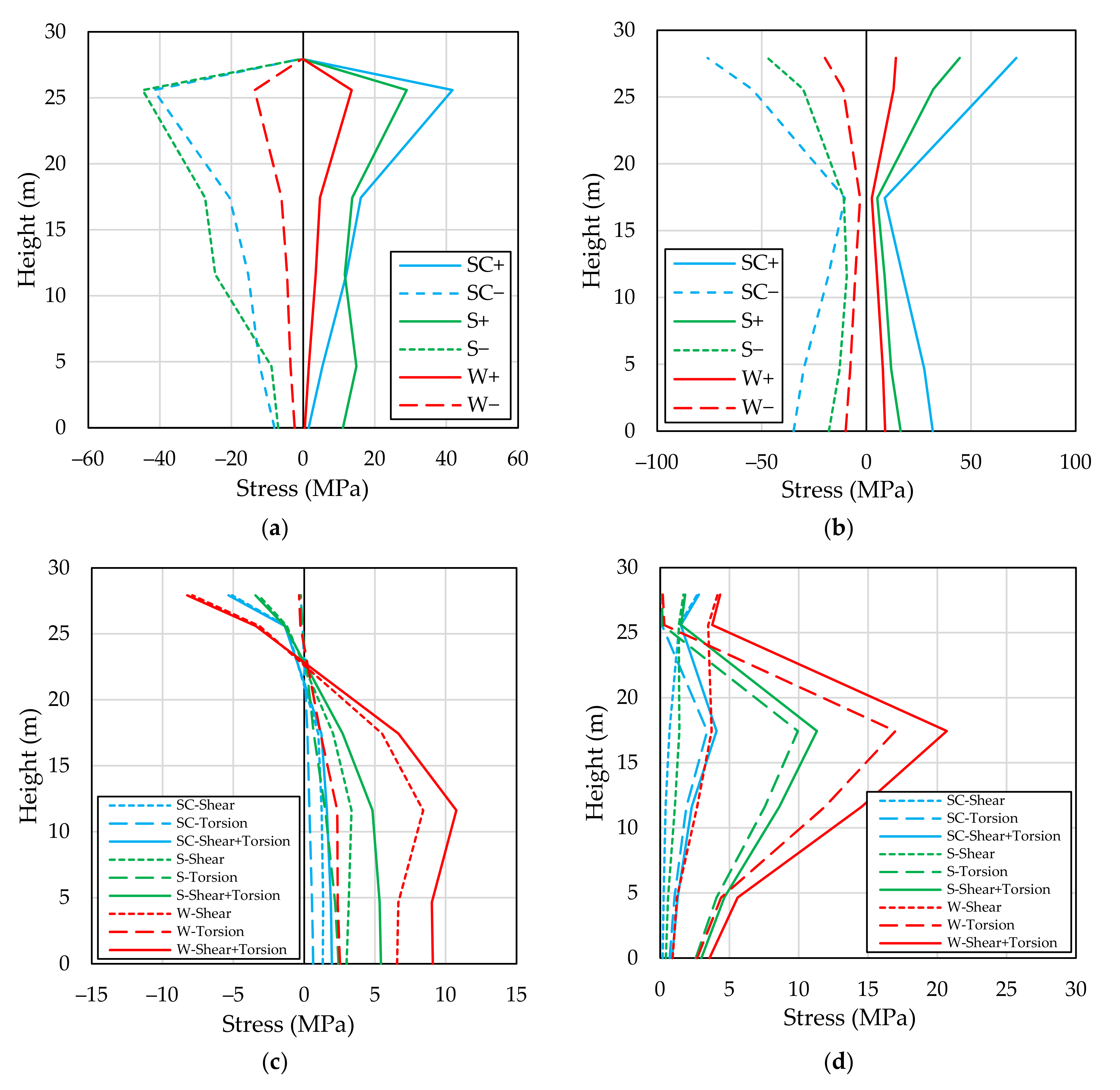
3. Comparison of Results with Governing Code Requirements

The design of the BladePole was performed using a Load and Resistance Design (LRFD) method (referred to as Limit States Design method in Eurocodes) shown in Equation (1). Equation (2) shows the Allowable Stress Design (ASD) method equation [24]. In the equations shown, ϕ is the resistance factor, Rn is the nominal strength, γi is the load factor, Qni is the load effect, and F.S. is the safety factor.
ϕ R n 1 i γ i Q n i
R n F . S . 1 i Q n i
Comprehensive standard codes do not exist for the design of FRP composite materials in civil engineering structures. However, such standards are under development. An ASCE pre-standard in the United States [25] and a European Commission (EC) design guidance document [26] form the basis for design in this work. ASCE-74 specifies that no load factors should be used for weather related loads (wind, ice) on transmission structures as these are extreme loads. Our analysis shows that dead and live loads are negligible relative to these extreme weather loads. NESC Table 253-1 provides load factors for design, and the load factor of 1.0 is prescribed for the wind and concurrent ice and wind cases that govern in the BladePole analysis described previously [21]. This is comparable to the load factors for wind in ASCE 7–16 as the winds are already “extreme” values and do not receive load factors greater than 1.0 in ASCE 7 [27]. In place of resistance factors (ϕ), material partial safety factors (γM) from the EC design guidance document are used. The material partial safety factors for FRP materials detailed in the EC guidance are a combination of several contributing partial factors. For uncertainties related to the material properties, γM1 is taken as 1.35. This assumes that the properties are derived from theoretical models (note that this value will be reduced in future work by the plan underway by the authors to test specimens from actual decommissioned wind turbine blades). For uncertainties related to the nature of the constituent parts and the production method, γM2 is taken as 1.35. This assumes production processes and properties with a standard deviation ≤0.10. If no post curing of the composite is used, then γM2 is further multiplied by 1.2. Thus, the partial material safety factor γM = 1.35 × 1.35 × 1.2 = 2.187. The nominal material properties were obtained using Helius Composite software [28]. The overall safety factor and allowable stresses obtained using this design method were calculated using Equations (3) and (4).
S a f e t y   F a c t o r = N o m i n a l   S t r e n g t h C a l c u l a t e d   S t r e s s f r o m   l o a d s
A l l o w a b l e   S t r e s s = N o m i n a l   S t r e n g t h Y M
The nominal strengths, allowable stresses, calculated stresses, and safety factors for the critical load cases are shown in Table 1. As can be seen, the lowest safety factor (4.19) was obtained from load case 2 at station 10 for the compressive stress in the shell of the wind blade section.
For the serviceability limit state (SLS), ASCE Manual of Practice 104 [29] gives guidance on recommended values for maximum deflections. The recommended values range from 8 to 15% of the aboveground height (AGH) for steel or concrete poles. These recommended values are used to design FRP poles in order to achieve serviceability equivalency to steel or concrete poles. The lower 8% limit gives a maximum allowed deflection of 2.538 m. The largest deflection of the proposed BladePole in the transverse direction was 315.5 mm and in the longitudinal direction 495.4 mm. These fall well below the maximum values and satisfy the manual of practice recommendation. It should be mentioned that Manual of Practice 104 notes that greater flexibility exists in FRP poles and considers this to be a positive characteristic. Where cases of unbalanced loadings occur (e.g., differential ice, sag/tension in unequal adjacent spans) these can be dissipated through deflections.

4. Conclusions

This paper has presented a preliminary study on a BladePole structure in which a decommissioned wind turbine blade is configured as a tangent pole with 230 kV capacity. The main findings are:
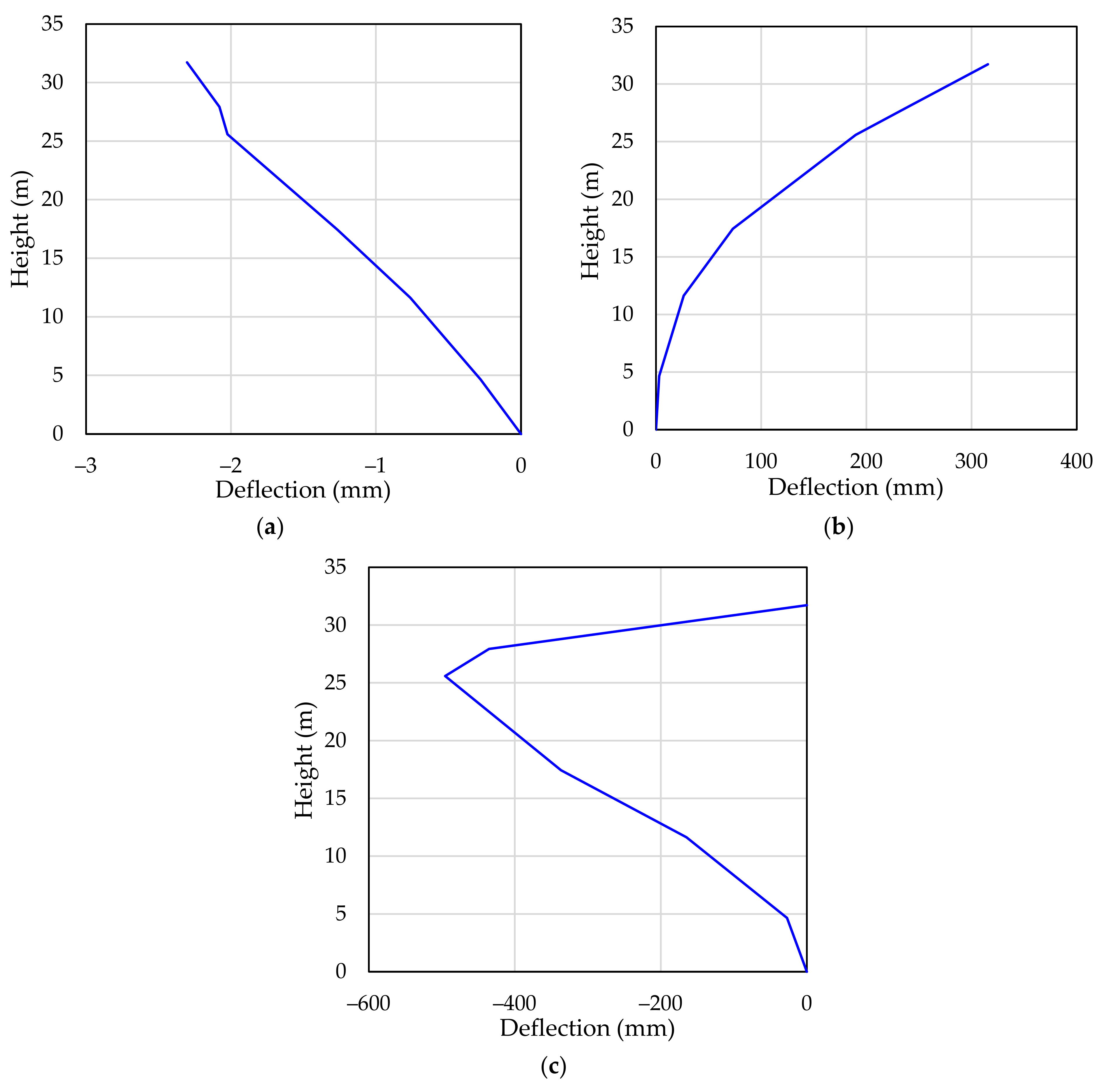
  • The BladePole application was shown to be adequate in ultimate and serviceability design limit states, in which the lowest safety factor is 4.19 and the maximum deflection is below the limit of 8% of the aboveground height (AGH).
  • The current configuration is intended for a 31.7 m high transmission pole; however, longer or shorter lengths of the wind blade can be cut to suit different heights and voltages.
  • The current configuration was designed and checked for a single circuit structure; however, double circuit configuration can be used and will create a degree of symmetry which may enhance the overall stress distribution and safety margins.
  • The BladePole application might be suitable for other situations (e.g., dead-end or corner pole applications), but these applications must be carefully analyzed as they have higher longitudinal and transverse loads.
  • Further analyses need to be conducted (e.g., finite element analyses) to analyze other limit states and complex load cases (e.g., galloping of conductors, vortex shedding of wind blades, and effect of lift and drag on a wind blade configured as a BladePole). Additionally, effect of material aging needs to be investigated to ensure material integrity in second-life applications.

Author Contributions

Conceptualization, A.A.A., L.C.B., D.W.S. and R.G.; methodology, A.A.A.; software, A.A.A.; validation, A.A.A.; formal analysis, A.A.A.; investigation, A.A.A.; resources, A.A.A., L.C.B., D.W.S. and R.G.; data curation, A.A.A.; writing—original draft preparation, A.A.A.; writing—review and editing, A.A.A., L.C.B., D.W.S. and R.G.; visualization, A.A.A. and R.G.; supervision, L.C.B., D.W.S. and R.G.; project administration, L.C.B., D.W.S. and R.G.; funding acquisition, L.C.B. and R.G. All authors have read and agreed to the published version of the manuscript.

Funding

This research was funded by the National Science Foundation (NSF) under grants 2016409, 1701413, and 1701694; by InvestNI/Department for the Economy (DfE) under grant 16/US/3334 and by Science Foundation Ireland (SFI) under grant USI-116 as part of the US-Ireland Tripartite research program.

Data Availability Statement

The data presented in this study are available upon request from the corresponding author.

Conflicts of Interest

The authors declare no conflict of interest. The funders had no role in the design of the study; in the collection, analyses, or interpretation of data; in the writing of the manuscript, or in the decision to publish the results.

References

  1. Liu, P.; Barlow, C.Y. Wind Turbine Blade Waste in 2050. Waste Manag. 2017, 62, 229–240. [Google Scholar] [CrossRef] [PubMed]
  2. Mishnaevsky, L.; Branner, K.; Petersen, H.N.; Beauson, J.; McGugan, M.; Sørensen, B.F. Materials for Wind Turbine Blades: An Overview. Materials 2017, 10, 1285. [Google Scholar] [CrossRef] [Green Version]
  3. Post, N.L. Modeling the Residual Strength Distribution of Structural GFRP Composite Materials Subjected to Constant and Variable Amplitude Tension-Tension Fatigue Loading. Master’s Thesis, Virginia Tech, Blacksburg, VA, USA, 2005. [Google Scholar]
  4. Nijssen, R.; Passipoularidis, V.; Smits, A.; Dutton, G.; Philippidis, T. Fatigue and Residual Strength of Rotor Blade Materials. In Proceedings of the European Wind Energy Conference and Exhibition (EWEC 2006), Athens, Greece, 27 February–2 March 2006; European Wind Energy Association: Athens, Greece, 2006; pp. 1796–1803. [Google Scholar]
  5. Post, N.L.; Case, S.W.; Lesko, J.J. Modeling the Variable Amplitude Fatigue of Composite Materials: A Review and Evaluation of the State of the Art for Spectrum Loading. Int. J. Fatigue 2008, 30, 2064–2086. [Google Scholar] [CrossRef]
  6. Bank, L.C.; Arias, F.R.; Yazdanbakhsh, A.; Gentry, T.R.; Al-Haddad, T.; Chen, J.-F.; Morrow, R. Concepts for Reusing Composite Materials from Decommissioned Wind Turbine Blades in Affordable Housing. Recycling 2018, 3, 3. [Google Scholar] [CrossRef] [Green Version]
  7. Suhail, R.; Chen, J.-F.; Gentry, T.R.; Tasistro-Hart, B.; Xue, Y.; Bank, L.C. Analysis and Design of a Pedestrian Bridge with Decommissioned FRP Windblades and Concrete. In Proceedings of the Fiber Reinforced Polymers in Reinforced Concrete Structures (FRPRCS14), Belfast, UK, 4–7 June 2019; IIFC: Belfast, UK, 2019; pp. 1–5. [Google Scholar]
  8. Gentry, T.R.; Al-Haddad, T.; Bank, L.C.; Arias, F.R.; Nagle, A.; Leahy, P. Structural Analysis of a Roof Extracted from a Wind Turbine Blade. J. Archit. Eng. 2020, 26, 04020040. [Google Scholar] [CrossRef]
  9. Joustra, J.; Flipsen, B.; Balkenende, R. Structural Reuse of High End Composite Products: A Design Case Study on Wind Turbine Blades. Resour. Conserv. Recycl. 2021, 167, 105393. [Google Scholar] [CrossRef]
  10. Joustra, J.; Flipsen, B.; Balkenende, R. Structural Reuse of Wind Turbine Blades through Segmentation. Compos. Part C Open Access 2021, 5, 100137. [Google Scholar] [CrossRef]
  11. André, A.; Kullberg, J.; Nygren, D.; Mattsson, C.; Nedev, G.; Haghani, R. Re-Use of Wind Turbine Blade for Construction and Infrastructure Applications. IOP Conf. Ser. Mater. Sci. Eng. 2020, 942, 012015. [Google Scholar] [CrossRef]
  12. Jensen, J.P.; Skelton, K. Wind Turbine Blade Recycling: Experiences, Challenges and Possibilities in a Circular Economy. Renew. Sust. Energy Rev. 2018, 97, 165–176. [Google Scholar] [CrossRef]
  13. Bank, L.C. Composites for Construction: Structural Design with FRP Materials; Wiley: Hoboken, NJ, USA, 2006. [Google Scholar]
  14. RS Composite Utility Poles. Available online: https://www.rspoles.com/ (accessed on 24 February 2021).
  15. Alshannaq, A.A.; Scott, D.W.; Bank, L.C.; Bermek, M.S.; Gentry, T.R. Structural Re-Use of De-Commissioned Wind Turbine Blades in Civil Engineering Applications. In Proceedings of the 34th Technical Conference of the American Society for Composites, Atlanta, Georgia, 23–25 September 2019; DEStech: Atlanta, Georgia, 2019. [Google Scholar] [CrossRef]
  16. Alshannaq, A.A.; Bank, L.C.; Scott, D.W.; Gentry, T.R. Structural Analysis of a Wind Turbine Blade Repurposed as an Electrical Transmission Pole. J. Compos. Constr. 2021, 25, 04021023. [Google Scholar] [CrossRef]
  17. Power Transmission Lines Framing and Configurations. Available online: http://www.powline.com/files/pls_pole/rus/RUSModels.html#StructureSchedule (accessed on 24 February 2021).
  18. RUS. Design Manual for High Voltage Transmission Lines; RUS 1724E-200; US Department of Agriculture: Honolulu, HI, USA, 2015; p. 374. Available online: https://www.rd.usda.gov/files/UEP_Bulletin_1724E-200.pdf (accessed on 6 July 2021).
  19. Ziemian, R.D.; McGuire, W. MASTAN2, V. 3.5.5. 2018. Available online: http://www.mastan2.com/ (accessed on 1 May 2020).
  20. ASCE. MOP 74-Guidelines for Electrical Transmission Line Structural Loading, 3rd ed.; ASCE: Reston, VA, USA, 2009; p. 204. [Google Scholar] [CrossRef]
  21. IEEE. National Electrical Safety Code; IEEE: New York, NY, USA, 2017; p. 360. [Google Scholar]
  22. Oden, J.T.; Ripperger, E.A. Mechanics of Elastic Structures; Hemisphere Publishing Corporation: New York, NY, USA, 1981. [Google Scholar]
  23. Kollar, L.P.; Springer, G.S. Mechanics of Composite Structures; Cambridge University Press: New York, NY, USA, 2003. [Google Scholar]
  24. Galambos, T.V. Load and Resistance Factor Design. Eng. J. 1981, 18, 74–82. [Google Scholar]
  25. ACMA. Pre-Standard for Load & Resistance Factor Design (LRFD) of Pultruded Fiber Reinforced Polymer (FRP) Structures; ASCE: Arlington, VA, USA, 2010; p. 215. [Google Scholar]
  26. Ascione, L.; Caron, J.-F.; Godonou, P.; van IJselmuijden, K.; Knippers, J.; Mottram, T.; Oppe, M.; Gantriis Sorensen, M.; Taby, J.; Tromp, L. Prospect for New Guidance in the Design of FRP: Support to the Implementation, Harmonization and Further Development of the Eurocodes; Publications Office of the European Union: Luxembourg, 2016. [Google Scholar]
  27. ASCE. Minimum Design Loads and Associated Criteria for Buildings and Other Structures, ASCE 7-16 ed.; ASCE: Reston, VA, USA, 2017; p. 889. [Google Scholar] [CrossRef]
  28. Autodesk. Autodesk Helius Composite V. 2016. Available online: https://www.autodesk.com/products/helius-composite/overview (accessed on 1 January 2020).
  29. ASCE. MOP 104-Recommended Practice for Fiber-Reinforced Polymer Products for Overhead Utility Line Structures, 2nd ed.; ASCE: Reston, VA, USA, 2019; p. 227. [Google Scholar] [CrossRef]
Figure 1. Clipper C96 blade configured as a tangent pole application (dimensions have been rounded to one decimal point).
Constrmater 01 00007 g001
Figure 2. Clipper C96 blade cross-sectional components.
Constrmater 01 00007 g002
Figure 3. Axial force, shear, and moment diagrams for: (a) load case 1; (b) load case 2; and (c) load case 3.
Constrmater 01 00007 g003
Figure 4. Diagrams for: (a) controlling axial stresses from load case 1; (b) controlling axial stresses from load case 2; (c) controlling shear stresses from load case 2; and (d) controlling shear stresses from load case 3.
Constrmater 01 00007 g004
Figure 5. Deflections for: (a) vertical direction from load case 1; (b) transverse direction from load case 1; and (c) longitudinal direction from load case 3.
Constrmater 01 00007 g005
Table 1. Nominal strengths, allowable stresses, calculated stresses, and safety factors for critical load cases.
Stress TypeStation NumberPart NameLoad Case
ShellSpar CapWeb
Nominal Compressive Strength (MPa)9197.67543.58145.621
Allowable Compressive Stress (MPa)90.39248.5566.58
Calculated Compressive Stress (MPa)44.8041.7513.56
Safety Factor (Compressive)4.4113.0210.74
Nominal Tensile Strength (MPa)9271.65806.82145.621
Allowable Tensile Stress (MPa)124.21368.9266.58
Calculated Tensile Stress (MPa)28.9141.6813.54
Safety Factor (Tensile)9.4019.3610.76
Nominal Compressive strength (MPa)10197.67453.47145.622
Allowable Compressive Stress (MPa)90.39207.3566.58
Calculated Compressive Stress (MPa)47.2075.9019.82
Safety Factor (Compressive)4.195.977.35
Nominal Tensile Strength (MPa)10271.65673.07145.622
Allowable Tensile Stress (MPa)124.21307.7666.58
Calculated Tensile Stress (MPa)44.5671.6514.05
Safety Factor (Tensile)6.109.3910.37
Nominal Shear Strength (MPa)10144.9372.74193.052
Allowable Shear Stress (MPa)66.2733.2688.27
Calculated Shear Stress (MPa)3.445.348.26
Safety Factor (Shear)42.1313.6223.38
Nominal Shear Strength (MPa)8144.9338.40193.053
Allowable Shear Stress (MPa)66.2717.5688.27
Calculated Shear Stress (MPa)11.314.0620.67
Safety Factor (Shear)12.819.469.34
Publisher’s Note: MDPI stays neutral with regard to jurisdictional claims in published maps and institutional affiliations.

