Article

Employing Robotics for the Biomechanical Validation of a Prosthetic Flipper for Sea Turtles as a Substitute for Animal Clinical Trials

BioDesign Lab, School of Engineering, Computer and Mathematical Sciences, Auckland University of Technology, City Campus, Auckland 1010, New Zealand
*
Author to whom correspondence should be addressed.
Biomechanics 2023, 3(3), 401-414; https://doi.org/10.3390/biomechanics3030033
Submission received: 19 June 2023 / Revised: 27 August 2023 / Accepted: 29 August 2023 / Published: 4 September 2023
(This article belongs to the Section Injury Biomechanics and Rehabilitation)

Abstract

:
Sea turtles are a keystone species for the ocean’s ecosystem, with all species currently being listed as endangered. Such a threat is mainly due to human factors such as fishing net entanglement. This entanglement often comes at the expense of turtles losing a pectoral flipper. The reduction in a sea turtle’s survival odds upon losing a flipper is a significant concern. This issue extends beyond individual animals, as the potential extinction of sea turtles could have detrimental effects on ocean health and subsequently disrupt our lifestyles. In this work, with the help of robotics, we tested the suitability of a prosthetic flipper for sea turtles that have lost a flipper. Testing with our sea-turtle-inspired robot helped to demonstrate the prosthetic flipper’s performance without clinical trials in live animals. The robot showed that the prosthetic could closely mimic the sea turtle’s downstroke and upstroke, allowing the animal to regain control in roll, pitch, and yaw, despite the absence of anatomical joints and related muscles. Additionally, swim speed tests provided an average swim speed of 0.487 m/s while dragging 6 m of cable to give a calculated maximum swim speed of 0.618 m/s, coming close to the average swim speed of wild sea turtles of 0.6 m/s. Our aspiration is that the findings from this study will pave the way for an open-source implant design, empowering veterinary professionals globally to aid injured turtles. Furthermore, this research promises to inspire additional animal-based robotic designs, advancing technologies geared towards assisting other animals in distress.

1. Introduction

Keystone species are recognised as playing an essential role in the form, function, and overall structural complexity of the ecosystem in which they live [1,2,3,4,5,6]. Sea turtles are known to modify their landscape through the way they feed [5]. Based on the classification, this makes the sea turtle an ecosystem engineer [7], as their feeding habits allow for coral to flourish by scavenging on coral competitors [5]. Sea turtles are essential not only to the ecosystem, but also for ecotourism [8], with large numbers of tourists visiting tropical locations around the world for the chance to swim with a wild sea turtle. However, not all is going well for this ecosystem engineer. All species of sea turtles are now listed under the endangered species act as threatened or endangered. The reason for this is highly complex, however, one thing that is clear is that large numbers of sea turtles every year are caught as bycatch in fishing nets [9,10]. The turtles that survive this traumatic incident frequently suffer from amputated or injured pectoral flippers [10] as a result of thrashing the flipper in a bid to release themselves. Additionally, during nesting, female sea turtles will return to land to lay approximately 50–200 eggs on the beach where they were born [11]. This enormous task could be physically impossible for a sea turtle with only one flipper. A possible solution to help these ecosystem engineers could be in the form of a prosthetic flipper. Prothesis in sea turtles has been utilised before, however, to the best of our knowledge, all attempts have come in the form of a flipper that straps onto the remaining limb. An example of this can be seen in the work produced by Sun et al. [12]. Although they reported promising results, their solution did not allow any rotation of the prosthetic for varying the flippers’ angle of attack (A.O.A.). This is a rather important design parameter to ensure that the desired thrust forces can be achieved.
In recent work by van der Geest et al. [13], sea turtle kinematics are detailed three-dimensionally based on the green sea turtle. They describe how the swimming pattern can be broken up into five stages consisting of the Downstroke (D.S.), Sweep stroke (S.S.), Recovery stroke one (R.S.1), Upstroke (U.S.), and Recovery stroke two (R.S.2) (Figure 1a,b). Additionally, they detail that the sweep stroke is mainly generated by the elbow joint. Assuming that the sea turtle amputation zone, as illustrated in Figure 1c, is located just before the elbow joint, this means that if the prosthesis was required to perform the sweep stroke, it would require some form of mechanised actuation. In such a case, challenges derived from the control system and signal acquisition actuation would emerge. Thus, building a complex mechanised prosthesis for a wild animal is not practically feasible, meaning a simple, fully mechanical, and robust solution is required for the success of such a project.
In this study, we designed and built a robotic sea turtle to test a fully mechanical prosthesis design. Thus, the robot and implanted animal only had to actuate the prosthesis in a simple roll motion without the sweep stroke. Hence, it could only produce a sea turtle’s up and down strokes without incorporating any control or electrical system. We considered only the downstroke and upstroke to simplify the prosthetic design and thus ensure a robust and simple mechanical operation. The A.O.A. was achieved passively with a soft rubber flipper to help mimic natural locomotion. Therefore, we evaluated whether a prosthetic flipper with no induced actuation mechanism at the elbow joint could be sufficient in propulsion and manoeuvrability. Although using a robot to help develop a prosthesis for sea turtles is potentially a world first, robotic test platforms have been extensively used for human prosthesis development [14,15,16].
The outcomes from the evaluations with our biomimetic robotic model elucidated the significant potential for an implanted turtle to recuperate the locomotive capabilities it has previously lost. Moreover, the prosthesis exhibited an impressive ability to visually replicate the natural kinetic patterns characteristic of a sea turtle’s up and down strokes. This visual mimicry underscores the successful integration of biological locomotion within the prosthetic design, suggesting a promising interface between the mechanical system and the biological organism. We hope our findings could lead to other animal-inspired robots to help develop technology for assisting other animals in need.

2. Methods

2.1. Design Overview and Objective

The primary objectives for these prosthetic flippers are multifaceted, aiming to restore the function and quality of life of sea turtles. Firstly, the prosthesis seeks to replicate turtle-inspired form and function, ensuring that a turtle can achieve effective aquatic locomotion. This involves producing sufficient thrust and providing the turtle with a sufficient manoeuvrability for activities such as evading predators and navigating various marine environments. Secondly, the prosthetic flipper should be durable and simple, requiring minimal maintenance. The criteria for evaluating the success of these prosthetics are grounded in both quantitative and qualitative measures. Quantitatively, this success can be measured by comparing the thrust and speed achieved with the prosthesis to that of a natural flipper. Additionally, the manoeuvrability will be judged based on reviewing simple videography of the robot performing simple roll, pitch, and yaw manoeuvres.

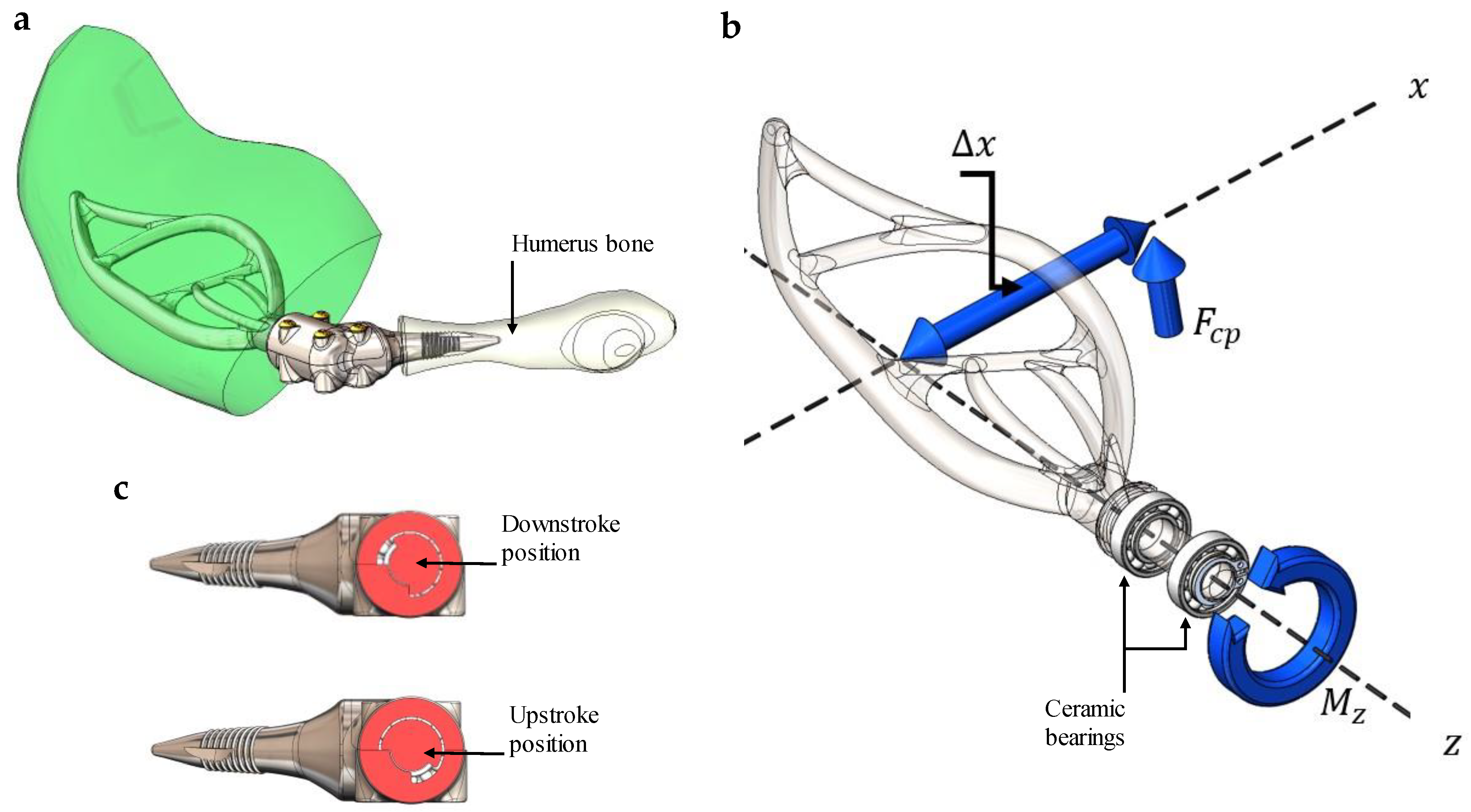
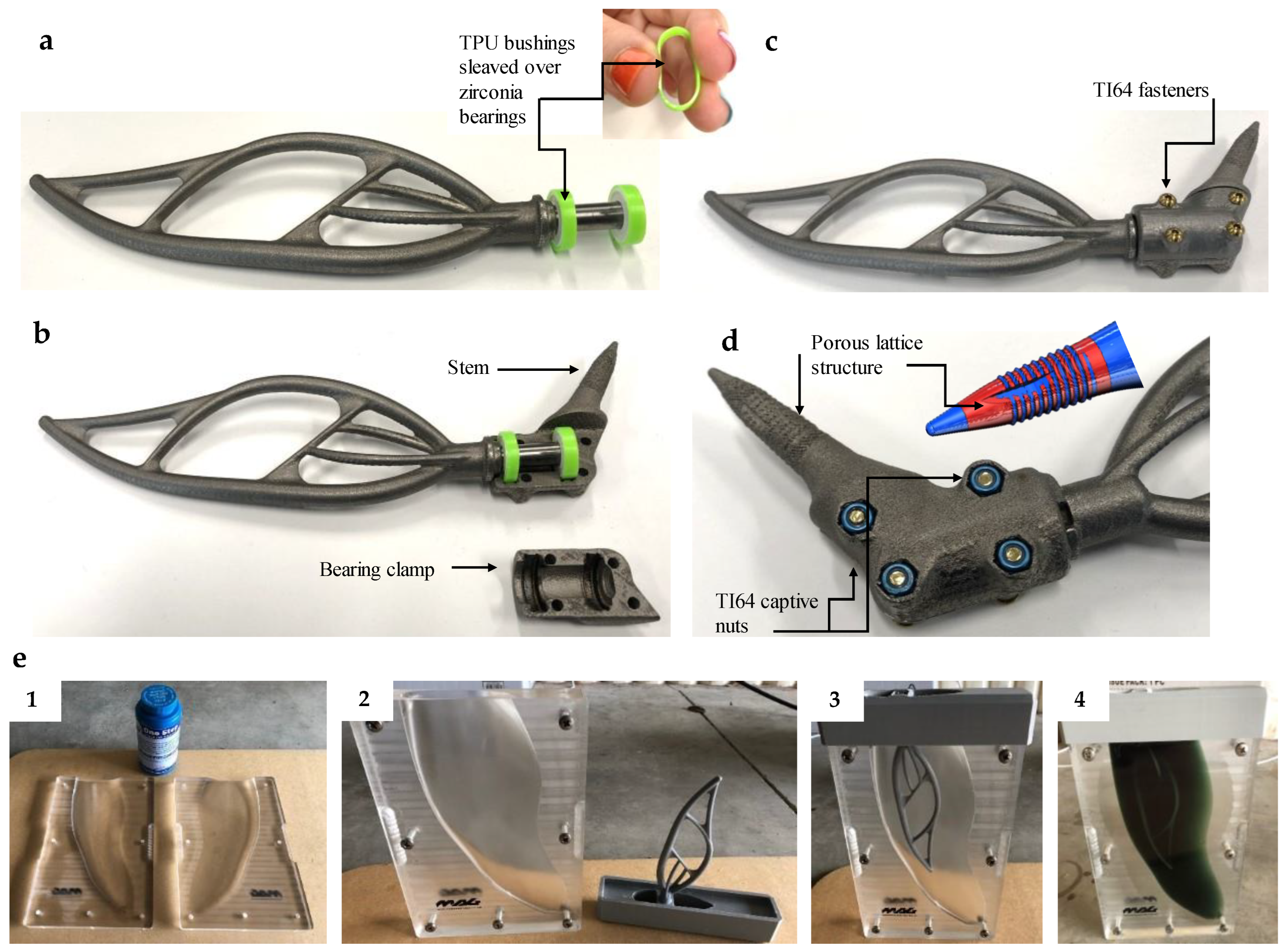
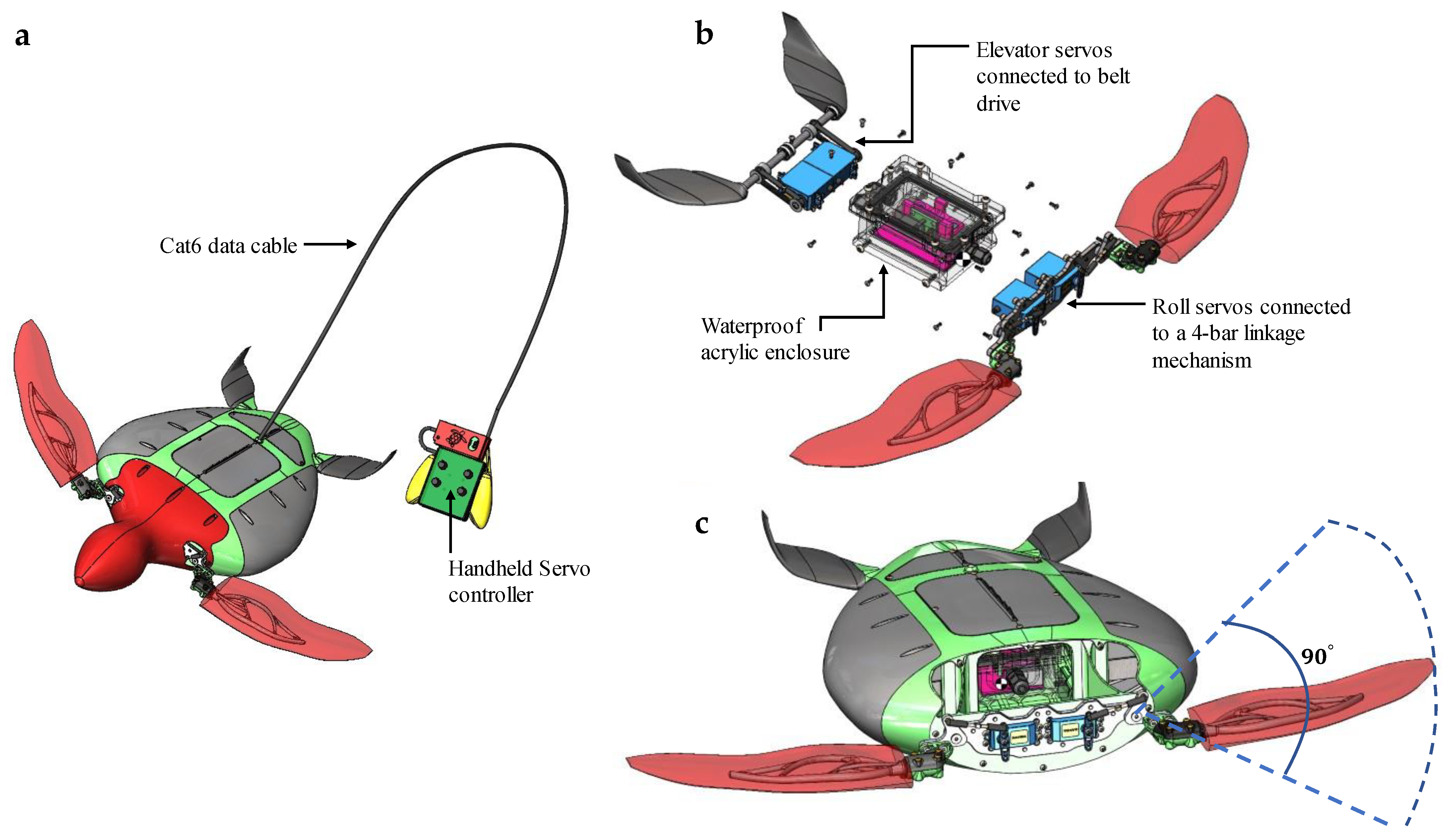
2.2. Prosthetic Flipper Design and Manufacturing

The prosthesis design was modelled in CAD (SP5.0, Solidworks 2019, Dassault Système, USA). The design process followed an iterative cycle using a finite element analysis (F.E.A.) (R19.1, ANSYS, Canonsburg, PA, USA), simulating loading from swimming and land-based locomotion. Loads were applied to the flipper body as a uniformly distributed load acting across the entire flipper surface. Initiating with a basic design concept and geometric framework for facilitating passive flipper rotation, we honed the geometry using a cycle of refinements in F.E.A. We adhered to this procedure until we achieved the sought-after stress distribution for both terrestrial and swimming locomotion, as depicted in Figure 2. The targeted stress was determined according to the fatigue life of Electron Beam Melting (EBM)-manufactured Ti64 [17].
For swimming, the loading was obtained from the study performed by van der Geest et al. [18] (Figure 2a,b) on freely swimming green sea turtles. As no prior literature was found for the loading case of land-based locomotion in sea turtles, some simplifications and assumptions had to be made. Given that sea turtles inherently display the behaviour of dragging their carapace across sandy terrain during terrestrial transit to and from their nesting locations, it was imperative to elucidate the potential friction coefficients existing between the carapace and the sand. This critical information was gleaned using a test rig conceptually modelled to emulate the underbelly of a turtle’s carapace (Figure 2f–i).
The rig was designed with an adjustable mass component, enabling normal and frictional load data estimations for various distinct loading scenarios. This customisable setup facilitated the experimental determination of diverse friction coefficients, thus enhancing our understanding of the carapace–sand interaction dynamic.
In order to ascertain the load imposed on each flipper during terrestrial locomotion, we simplified our calculations by assuming a state of static equilibrium. This assumption was deemed appropriate due to the characteristically low velocity of sea turtles during land transit, resulting in negligible acceleration. Moreover, we postulated that the pectoral flippers would bear approximately half of the turtle’s vertical load, with the rear flippers primarily contributing to the propulsive force, rather than supporting the turtle’s weight (Figure 2e). The loading for each flipper was then calculated with Equations (1)–(3):
R a = m f B ( A + B )
R b = m f A ( A + B )
μ R b = F f
where R a is the total load in the vertical direction experienced by both pectoral flippers and R b is the total vertical load acting on the turtle’s shell. The turtle’s mass is represented as m f , with A and B representing the distance from the turtle’s centre of mass to the reaction points R a and R b . The friction force F f between the sand and the shell is found using an experimental coefficient of friction value μ .
The flipper’s A.O.A. was achieved passively by designing the flipper to rotate on a transmission shaft held in place by two ceramic bearings (Figure 3a–c). The torque ( M z ) to rotate the flipper into its downstroke and upstroke positions passively can be modelled using:
M z = F c p x
where F c p is the force acting at the centre of pressure at a distance x from the flipper rotation axis (Figure 3b).
The stem was designed with a porous lattice structure to promote bone ingrowth and help lower stress shielding [19,20,21]. The stem and internal flipper structure were additively manufactured using electron beam manufacturing (EBM) technology from titanium alloy (Ti64). CAD Models were processed using Solidworks 2019 SP5.0 and then exported to S.T.L. mesh files. The S.T.L. Mesh files were prepared in the Materialise Magics 23 software (Materialise, Leuven, Belgium). The turtle stems were built on an Arcam Q10plus EBM machine (General Electric, Boston, MA, USA) with the SOP17:1 running EBMControl 5.0 software. The solid regions of the component were built using a standard process melt theme with a 0.05 mm layer thickness. The porous structure was generated using Materialize Magics 23, using the Structures module. This used a 0.60 mm unit cell with a 0.05 mm overlap in x, y, and z and a 45 degree growth angle. This generated a mesh with a 0.27 mm strut diameter. The porous structure was built using the standard N.E.T. process theme with a 0.05 mm layer thickness.
The main bearing housing was bolted together with four Ti64 fasteners, as seen in Figure 4a–d. The two ceramic bearings were installed with 98A T.P.U. bushings to reduce the chances of impact loads damaging the bearings. After printing, the transmission shaft and bearing races were machined to achieve the required bearing tolerances. The soft flipper was manufactured by casting 70A polyurethane rubber over the flipper’s internal structure using a split mould assembly. Shore A 70 hardness polyurethane rubber was used, as it gave what we felt was the best compromise between bio-mimicking the natural flipper flex and a structural resistance to hydrodynamic loads. Additionally, the lid of the mould assembly acted as a holding jig to precisely position the flipper structure within the correct design location of the overall flipper geometry, as seen in Figure 4e.

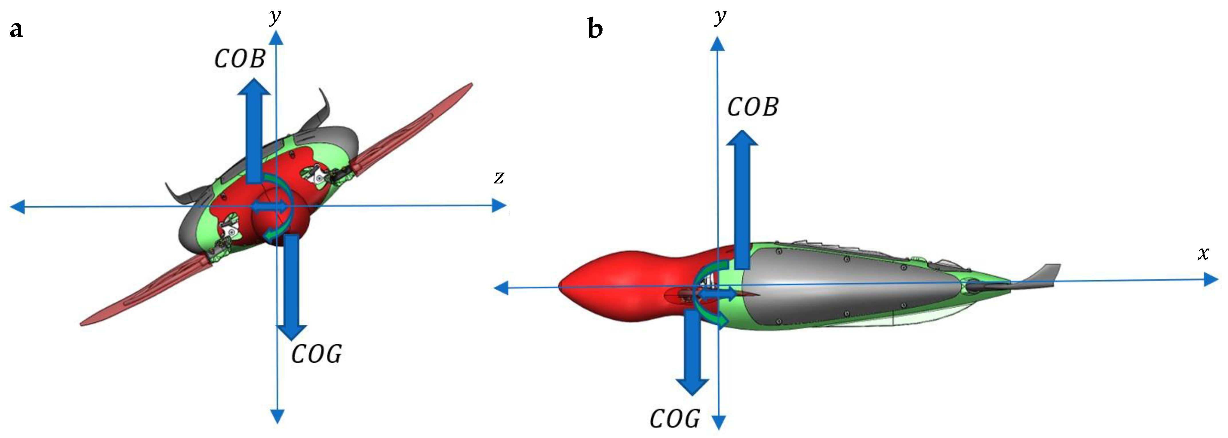
2.3. Sea-Turtle-Inspired Robot Design and Manufacture

As previously explained, the swimming cycle of sea turtles is composed of five distinct stages, namely (D.S.), (S.S.), (R.S.1), (U.S.), and (R.S.2). The S.S. and R.S.1 phases are predominantly enabled by articulating the turtle’s elbow joint. Without this joint, as a result of amputation, only the D.S. and U.S. stages can be attained. This understanding aids in streamlining the design process for both the robotic model and prosthesis, as the designs need only facilitate a simple roll motion coupled with a passive pitching rotation, as depicted in Figure 5.
The robot’s carapace, as illustrated in Figure 5a,b, was intentionally simplified relative to the intricate form of a natural sea turtle. This was achieved by designing a body symmetrical in both the sagittal and coronal planes. Moreover, the carapace’s overall volume was reduced, thereby decreasing the required material volume and consequently simplifying the manufacturing process. It is worth mentioning that, despite these modifications for practicality, the robotic model retained an overall form that was heavily inspired by sea turtles.
These design choices are justified by the need for technical efficiency, material economy, and manufacturing simplicity. The iterative process of developing a bio-inspired robotic system necessitates these simplifications as a practical compromise between a biologically accurate representation and feasible engineering solutions. The objective is to attain a balance between biological mimicry and operational efficiency, ensuring the robotic model can adequately perform its testing role for the prosthesis.
Using additive manufacturing equipment, the turtle-inspired robot chassis was 3D printed from PLA+ filament (Esun, Shenzhen, China). The printing was performed with an FDM machine (Caribou Mk3s, Caribou, Remagen, Germany), with the model being sliced into 0.16 mm layer heights and printed with a 40% honeycomb infill. The front transmission assembly used two Savox SW-0231MG servos (Savox, Taichung City, Taiwan). The servos were bolted to a C.N.C. machined adaptor plate that connected the prosthetic flippers to the servo motors with two four-bar linkage mechanisms made from titanium turnbuckles (Figure 6a–c) to produce a maximum roll amplitude of 90° (Figure 6c). The same servo motors actuated the rear flippers. However, the actuation went through a simple belt drive with a 1:1 drive ratio (Figure 6b). To achieve the correct buoyancy, the chassis was designed to allow water ingress, except for a small acrylic box that kept the non-waterproof electronics dry (Figure 6b). Power was sent to the four servo motors via a 6.6 V, 4 C, 1800 mAh LiFe battery (Muchmore Racing, Seoul, Republic of Korea) that was also housed inside the watertight enclosure.
To avoid the necessity for a control system to maintain stability, the robotic model was strategically engineered to exhibit an inherent stability. This was achieved by ensuring that the centre of buoyancy (C.O.B.) was above the robot’s centre of gravity (C.O.G.), as viewed from the y-z plane in Figure 7a to generate a natural righting moment.
Sea turtles produce a more aggressive downstroke compared to their upstroke [13,18,22,23,24]. To offset this powerful downstroke and help the robot to swim levelly, the C.O.G. was designed to be frontwards of the C.O.B., as seen from the x-y plane in Figure 7b. This caused the robot to pitch noise down when it was stationary and level out during its swimming operation. The robot operator generated the servo actuation via a handheld controller, as seen in Figure 6a. This allowed the operator to control each servo actuation as needed to perform the desired motion underwater.
To ensure a naturally stable robot during swimming, as described before, the C.O.G. and C.O.B. needed to be precisely positioned relative to one another. To accomplish this, a complete CAD model of the robot, including every nut, bolt, and circuit board, along with the correct volumes and masses, was defined within the CAD model to create a virtual clone of the robot assembly. This allowed for the C.O.G. to be atomically calculated within CAD relative to the C.O.B.
Calculating the C.O.B. required the CAD model to be converted into water by defining all the solid bodies within the entire assembly as the density of water. Additionally, the watertight enclosure had to be remodelled as a solid body (no longer hollow) to ensure that the correct fluid volumes were obtained. This process was iterated in CAD by tuning the internal geometry of the robot model until the desired C.O.B. and C.O.G. positions were obtained within the CAD virtual space.
During the manufacturing process, each part and sub-assembly were weighed after manufacturing to ensure their mass properties matched the virtual part from CAD. The virtual robot’s mass was 2507.2 g and that of the final completely assembled robot was 2507 g. As a result of this design process within the CAD virtual environment, the robot achieved perfect buoyancy in the water column and required no trimming.

3. Results and Discussion

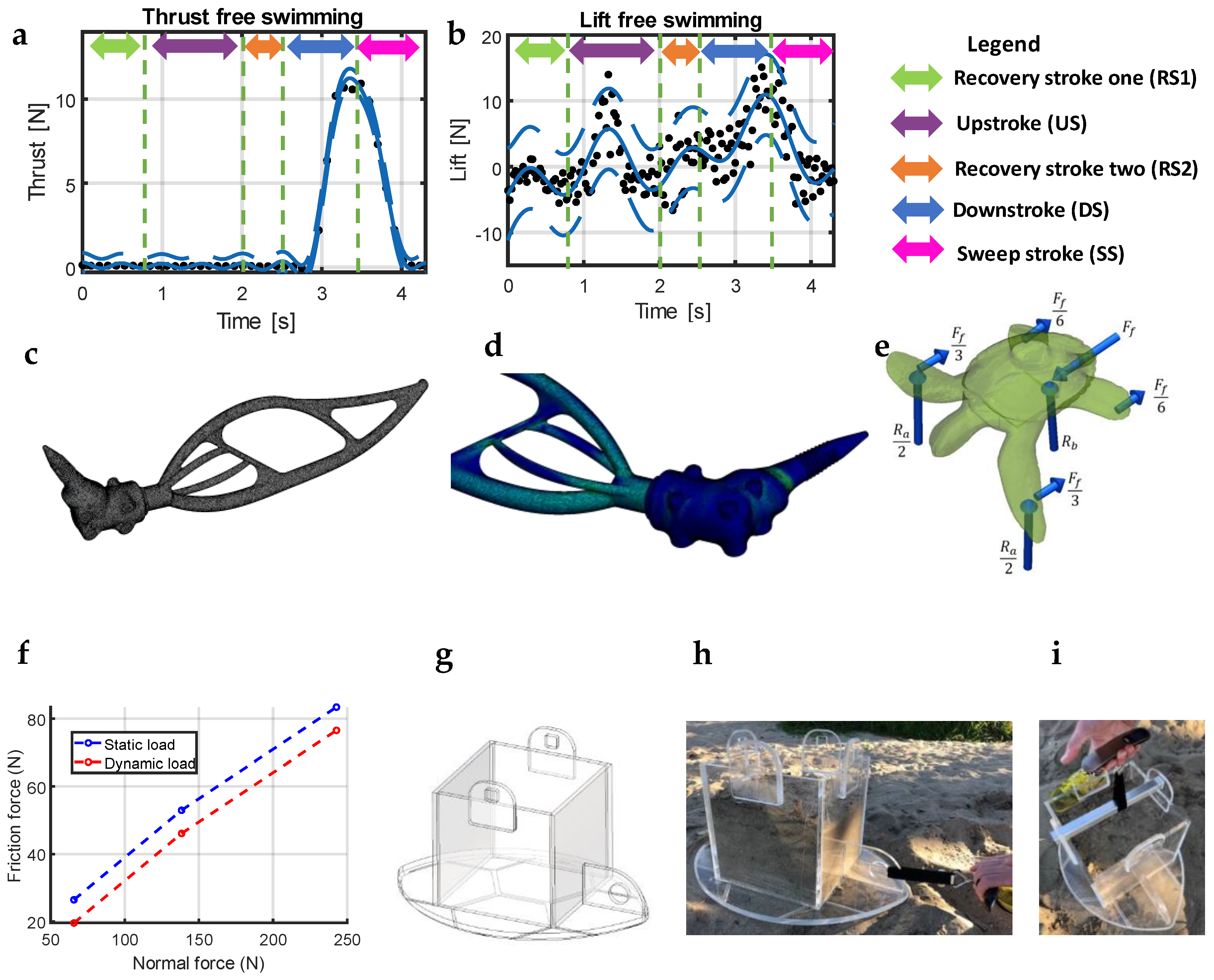
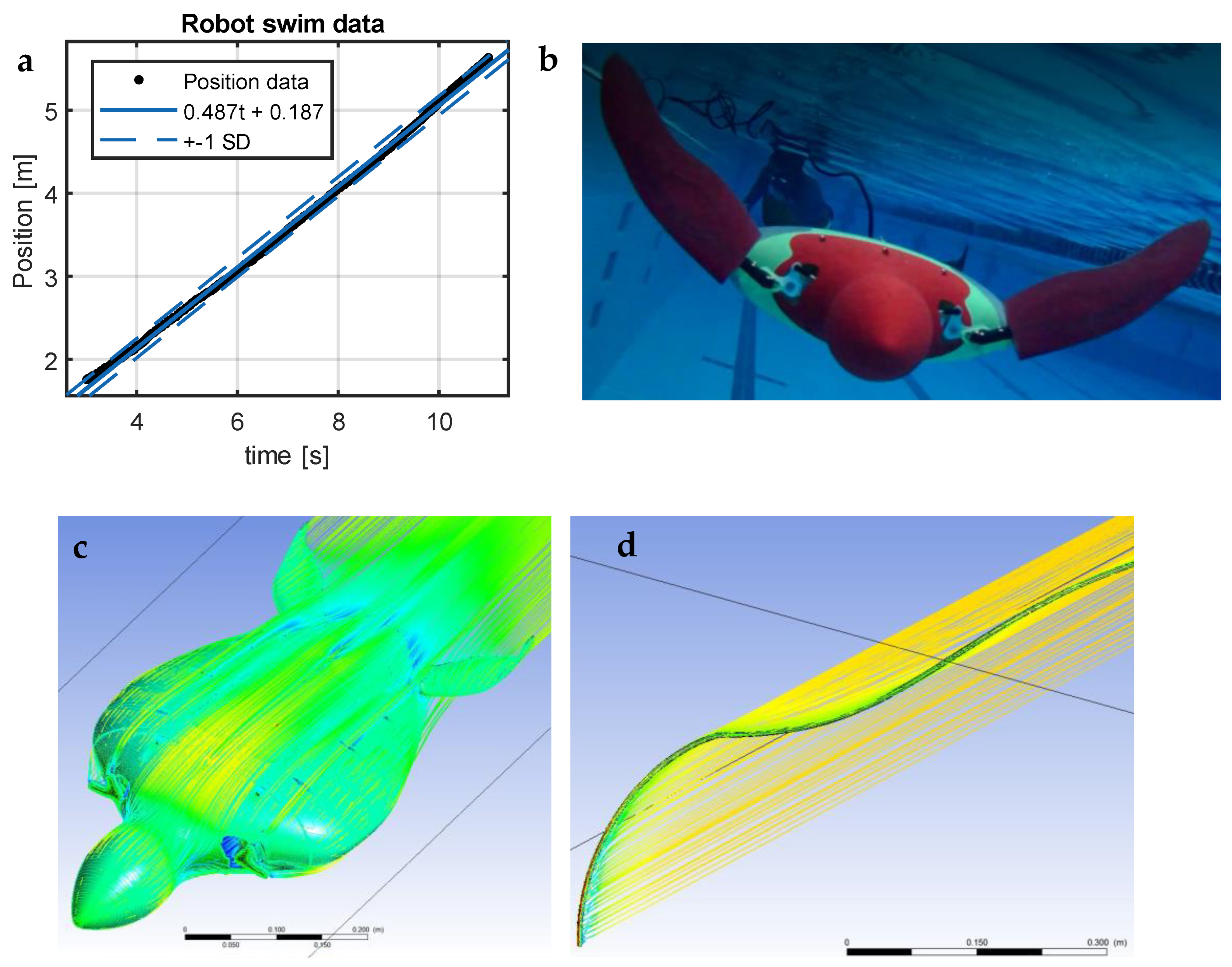
3.1. Swim Speed and Average Thrust Generation

All the swim tests were performed using the AUT Millennium Centre’s high-performance training facilities in Auckland, New Zealand. The centre utilises an internal system named “Video tracking”. Video tracking is used to measure the swim speed of Olympic athletes during their training sessions. It is programmed to follow red objects from multiple gigabit ethernet cameras built into the pool roof, thus allowing for the swim speed to be easily calculated by differentiating the position data (Figure 8a). The robot’s head and flippers were manufactured as red to take advantage of this Video tracking and find the swim speed of the robot. Due to the robot’s low drag, the cable did produce significant interference during swimming compared to the body’s drag forces. Despite this, the robot produced a maximum swim speed of 0.487 ± 0.001 m/s at a flapping frequency of 0.9 Hz while dragging 6 m of cat6 data cable underwater (Figure 8b).
An estimated theoretical max swim speed was calculated for the robot without a data cable with the help of C.F.D. ANSYS CFX (ANSYS 2019 R2, Canonsburg, PA, USA). The C.F.D. code used the k e model for two separate simulations, one with the robot and one with the cable (Figure 8c,d). The simulation for the robot was performed without flippers, as they are propulsion generators rather than drag generators, with the cable being modelled as per the video footage in Figure 8b. The simulations predicted drag coefficients ( c d ) of 0.205 for the robot and 0.364 for the cable. Based on the c d of the cable and robot, a total drag force ( F t o t a l ) of 1.239 N was calculated for 0.487 m/s. From this, the estimated maximum swim speed of 0.618 m/s was calculated using:
V m a x = 2 F t o t a l ρ A c d
where A and c d are the frontal area and drag coefficient of the robot’s body only. Given that the robot was swimming at a constant velocity, the total drag force can be mathematically equated to the average thrust generation. Through our analysis, we ascertained that the robot with the prosthesis produced an average thrust of 1.239 N, utilising a basic roll and pitch motion. Drawing comparisons with a study by van der Geest et al. [18], a wild sea turtle with comparable dimensions generates an average thrust of 2.4 N during its typical swimming activities. While the prosthetic flippers recaptured only approximately 50% of this native thrust, it is noteworthy to emphasise that this is a significant improvement over having no flipper at all. This demonstrates that even the rudimentary motion facilitated by the prosthesis can offer meaningful propulsion, underscoring its potential utility for locomotion.

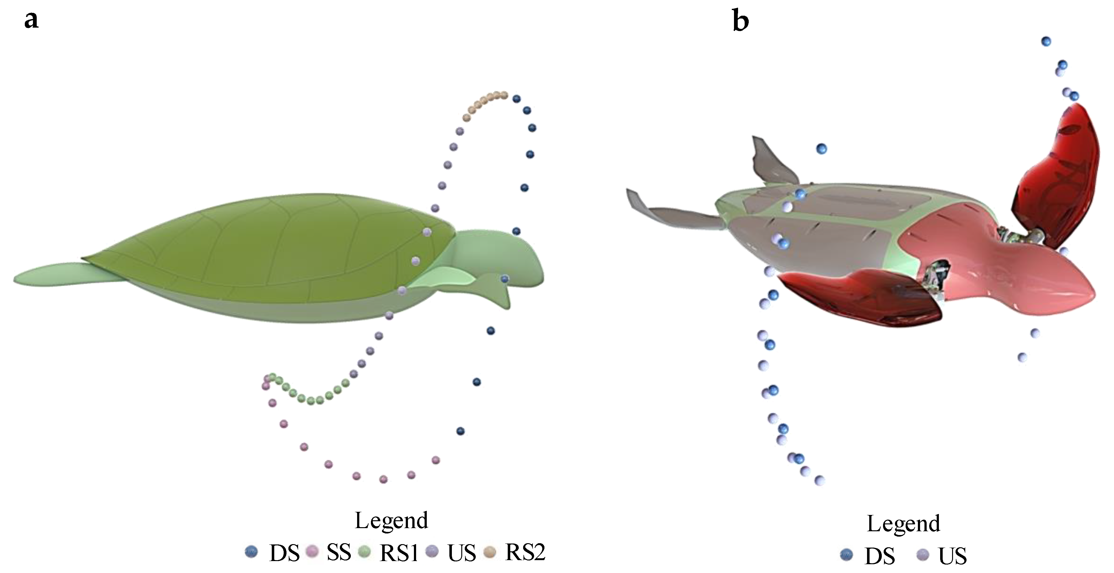
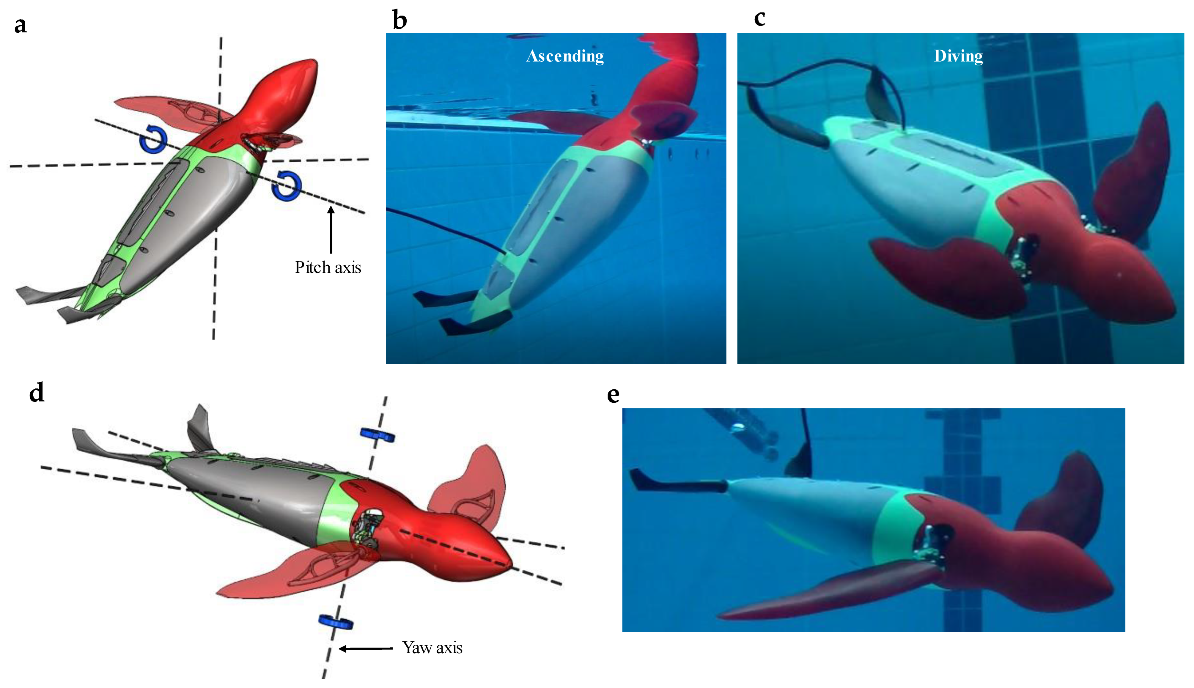
3.2. Manoeuvrability Tests

While motion capture techniques were employed to determine the swim speed, these methods proved ineffective in capturing the roll, pitch, and yaw motions during the swim tests. In order to support these motions, we employed underwater videography (Movie S1). While relying on videography data can be considered as a more qualitative approach, the footage showed that the prosthesis performed admirably in executing roll, pitch, and yaw motions based on basic user inputs (Figure 9a–e).
For instance, the yawing action to steer the robot left and right (Figure 9d,e) was realised by having the operator modulate the speed of the left or right flipper, thereby generating the desired thrust vector. Yaw motions could be adeptly executed both during full-speed swimming and when stationary. Similarly, the robot’s pitch was controlled by altering the frequency of the upward and downward strokes relative to one another while concurrently adjusting the angle of the rear flippers/elevators, as depicted in Figure 9a–c. This adaptive strategy, wherein simple adjustments to the flipper movements resulted in complex and precise manoeuvres such as yaw and pitch, underscores the efficacy and versatility of the prosthesis in mimicking authentic sea turtle locomotion. The notable aspect of this finding lies not merely in replicating these complex movements, but through intuitive controls and uncomplicated modifications to flipper speed.
When evaluating the locomotion patterns of our robot fitted with the prosthetic flipper, focusing on the downstroke, upstroke, and wing rotation phases, a striking similarity was evident when compared to a green sea turtle’s natural movements, as depicted in Figure 10. These parallels offer significant insights into the biomechanical fidelity of our robotic design. However, a discernible deviation was noticeable in how the flipper articulated during each phase. The green sea turtle can morph and twist its flipper in its natural environment, providing multifaceted control over its aquatic manoeuvres. Conversely, our prosthetic design, bounded by current technological constraints, limited the flipper’s movement to rotation along a singular axis, as illustrated in Figure 10 under the wing twist column.
This distinction, while noteworthy, was a conscious design decision rooted in prioritising mechanical durability and simplicity. As alluded to in our previous discussions about removing the sweep stroke, the design’s simplification to mere rotation minimised the number of potential failure points. This decision not only ensured the longevity and reliability of the prosthesis, but also streamlined the engineering challenges, offering a robust solution that, while not perfectly emulating nature, struck a balance between biomechanical accuracy and mechanical pragmatism.

4. Conclusions and Future Work

In this research, we conceptualised and constructed a robotic sea turtle to evaluate a purely mechanical prosthetic design. The robotic model, representing the prospective implanted animal, was engineered to actuate the prosthesis through a basic roll and passive pitch motion, excluding the sweep stroke. This approach allowed us to emulate the sea turtle’s up and down strokes. The study showed that the prosthesis could allow for an implanted animal to regain intricate movements, such as roll, yaw, and pitch, through relatively straightforward inputs.
The average thrust generated by the prosthesis, though presently amounting to roughly half of that which wild sea turtles can produce, holds particular promise. This thrust enhancement, even in the absence of a complete Sweep Stroke (S.S.) that characterises the natural propulsion cycle of turtles, demonstrates a marked improvement over having no flipper at all.
However, while filled with potential, some limitations require discussion. A significant limitation was the motion capture techniques’ inability to accurately track the stationary roll, pitch, and yaw motions during the swim tests. Though invaluable, our dependence on underwater videography did not provide the quantitative precision desired, especially in capturing the nuances of the thrust dynamics and various motions.
Moving forward, the goal is not merely to optimise the design, but to understand and develop the complete integration of the prosthesis with a sea turtle’s body, which will require animal trials. Detailed attention must be paid to the stem and the intricacies of the implantation procedures. Every surgical step, from the initial incision to the post-surgical aftercare, plays a crucial role in ensuring that the prosthesis remains anchored and can deliver the requisite thrust without complications.
However, the challenges do not end post-surgery. The animal with an implanted limb will need comprehensive rehabilitation programs designed to familiarise them with the unique thrust dynamics of their new appendage, ensuring that they can regain and maybe even exceed their previous swimming capabilities. Through this rehabilitation, the goal is to restore physical function and bolster the turtle’s confidence in navigating aquatic terrains with their new prosthetic.
Even though we currently cannot replicate the complete S.S. with the prosthesis, and thus the entire swimming cycle is not 100% mimicked, the results are promising.
Collaborations with marine biologists, veterinary surgeons, and biomechanics experts will be instrumental. Their combined expertise can push the boundaries of what is possible for rehabilitating injured sea turtles and advancing the frontiers of bioinspired robotic design. Both authors of this communication welcome the international scientific community for future collaborations.
Wrapping up, the technology presented in this communication could offer a lifeline for injured sea turtles requiring prosthetic support, enabling naturalistic movement patterns crucial for their survival. The ability to emulate such intricate and nuanced motions of an actual sea turtle using a relatively simple and controllable prosthetic system highlights an innovative intersection of biology, technology, and engineering that could have far-reaching impacts. Given the inherent simplicity of the prosthesis operation, it is entirely plausible that a sea turtle, renowned for its adaptability, could learn to utilise this prosthetic flipper effectively.

Supplementary Materials

The following supporting information can be downloaded at: https://www.mdpi.com/article/10.3390/biomechanics3030033/s1, Movie S1: Robot swim tests.

Author Contributions

All authors contributed equally to this work. All authors have read and agreed to the published version of the manuscript.

Funding

This research received no external funding.

Institutional Review Board Statement

Not applicable.

Informed Consent Statement

Not applicable.

Data Availability Statement

All data sets for the current study are available from the authors on reasonable request, via contacting correspondence author.

Acknowledgments

M.A.G. Assembly for contributing to the manufacturing of robot components. Zenith Technica for manufacturing the EBM-manufactured components. Gowings Whale Trust for their assistance towards logistics and encouragement for further work.

Conflicts of Interest

The authors declare no competing interests.

References

  1. Garibaldi, A.; Turner, N. Cultural Keystone Species: Implications for Ecological Conservation and Restoration. Ecol. Soc. 2004, 9, 1. [Google Scholar] [CrossRef]
  2. Coleman, F.C.; Williams, S.L. Overexploiting marine ecosystem engineers: Potential consequences for biodiversity. Trends Ecol. Evol. 2002, 17, 40–44. [Google Scholar] [CrossRef]
  3. Hannan, L.B.; Roth, J.D.; Ehrhart, L.M.; Weishampel, J.F. Dune vegetation fertilization by nesting sea turtles. Ecology 2007, 88, 1053–1058. [Google Scholar] [CrossRef] [PubMed]
  4. Houghton, J.D.R.; Doyle, T.K.; Wilson, M.W.; Davenport, J.; Hays, G.C. Jellyfish Aggregations and Leatherback Turtle Foraging Patterns in a Temperate Coastal Environment. Ecology 2006, 87, 1967–1972. [Google Scholar] [CrossRef] [PubMed]
  5. Martins, R.F.; Andrades, R.; Nagaoka, S.M.; Martins, A.S.; Longo, L.L.; Ferreira, J.S.; Bastos, K.V.; Joyeux, J.-C.; Santos, R.G. Niche partitioning between sea turtles in waters of a protected tropical island. Reg. Stud. Mar. Sci. 2020, 39, 101439. [Google Scholar] [CrossRef]
  6. Davic, R.D. Linking Keystone Species and Functional Groups: A New Operational Definition of the Keystone Species Concept. Conserv. Ecol. 2003, 7, 1. [Google Scholar] [CrossRef]
  7. Lawton, J.H.; Jones, C.G. Linking Species and Ecosystems: Organisms as Ecosystem Engineers. In Linking Species & Ecosystems; Jones, C.G., Lawton, J.H., Eds.; Springer: Boston, MA, USA, 1995; pp. 141–150. [Google Scholar] [CrossRef]
  8. Tisdell, C.; Wilson, C. Ecotourism for the survival of sea turtles and other wildlife. Biodivers. Conserv. 2002, 11, 1521–1538. [Google Scholar] [CrossRef]
  9. Lewison, R.L.; Crowder, L.B. Putting Longline Bycatch of Sea Turtles into Perspective. Conserv. Biol. 2007, 21, 79–86. [Google Scholar] [CrossRef]
  10. Stelfox, M.; Bulling, M.; Sweet, M. Untangling the origin of ghost gear within the Maldivian archipelago and its impact on olive ridley (Lepidochelys olivacea) populations. Endanger. Species Res. 2019, 40, 309–320. [Google Scholar] [CrossRef]
  11. Davenport, J. Temperature and the life-history strategies of sea turtles. J. Therm. Biol. 1997, 22, 479–488. [Google Scholar] [CrossRef]
  12. Sun, X.; Kato, N.; Matsuda, Y.; Kanda, K.; Kosaka, Y.; Kamezaki, N.; Taniguchi, M. Three-dimensional Hydrodynamic Analysis of Forelimb Propulsion of Sea Turtle with Prosthetic Flippers. J. Aero Aqua Bio-Mech. 2013, 3, 36–44. [Google Scholar] [CrossRef]
  13. van der Geest, N.; Garcia, L.; Nates, R.; Godoy, D.A. New insight into the swimming kinematics of wild Green sea turtles (Chelonia mydas). Sci. Rep. 2022, 12, 18151. [Google Scholar] [CrossRef] [PubMed]
  14. Ayub, R.; Villarreal, D.; Gregg, R.D.; Gao, F. Evaluation of transradial body-powered prostheses using a robotic simulator. Prosthetics Orthot. Int. 2017, 41, 194–200. [Google Scholar] [CrossRef] [PubMed]
  15. Caputo, J.M.; Collins, S.H. An experimental robotic testbed for accelerated development of ankle prostheses. In Proceedings of the 2013 IEEE International Conference on Robotics and Automation, Karlsruhe, Germany, 6–10 May 2013; pp. 2645–2650. [Google Scholar]
  16. Kashef, S.R.; Amini, S.; Akbarzadeh, A. Robotic hand: A review on linkage-driven finger mechanisms of prosthetic hands and evaluation of the performance criteria. Mech. Mach. Theory 2019, 145, 103677. [Google Scholar] [CrossRef]
  17. Vayssette, B.; Saintier, N.; Brugger, C.; Elmay, M.; Pessard, E. Surface roughness of Ti-6Al-4V parts obtained by SLM and EBM: Effect on the High Cycle Fatigue life. Procedia Eng. 2018, 213, 89–97. [Google Scholar] [CrossRef]
  18. van der Geest, N.; Garcia, L.; Borret, F.; Nates, R.; Gonzalez, A. Soft-robotic green sea turtle (Chelonia mydas) developed to replace animal experimentation provides new insight into their propulsive strategies. Sci. Rep. 2023, 13, 11983. [Google Scholar] [CrossRef]
  19. Pilliar, R.M.; Cameron, H.U.; Binnington, A.G.; Szivek, J.; Macnab, I. Bone ingrowth and stress shielding with a porous surface coated fracture fixation plate. J. Biomed. Mater. Res. 1979, 13, 799–810. [Google Scholar] [CrossRef]
  20. Jafari Chashmi, M.; Fathi, A.; Shirzad, M.; Jafari-Talookolaei, R.-A.; Bodaghi, M.; Rabiee, S.M. Design and Analysis of Porous Functionally Graded Femoral Prostheses with Improved Stress Shielding. Designs 2020, 4, 12. [Google Scholar] [CrossRef]
  21. Arabnejad, S.; Johnston, B.; Tanzer, M.; Pasini, D. Fully porous 3D printed titanium femoral stem to reduce stress-shielding following total hip arthroplasty. J. Orthop. Res. 2016, 35, 1774–1783. [Google Scholar] [CrossRef]
  22. van der Geest, N.; Garcia, L.; Nates, R.; Gonzalez-Vazquez, A. Sea Turtles Employ Drag-Reducing Techniques to Conserve Energy. J. Mar. Sci. Eng. 2022, 10, 1770. [Google Scholar] [CrossRef]
  23. Davenport, J.; Munks, S.A.; Oxford, P.J. A comparison of the swimming of marine and freshwater turtles. Proc. R. Soc. London. Ser. B Boil. Sci. 1984, 220, 447–475. [Google Scholar] [CrossRef]
  24. Booth, D.T. Kinematics of swimming and thrust production during powerstroking bouts of the swim frenzy in green turtle hatchlings. Biol. Open 2014, 3, 887–894. [Google Scholar] [CrossRef] [PubMed]
Figure 1. Sea turtle kinematics patterns obtained from van der Geest et al. [13]. Blue spheres represent the wingtip trajectory for the downstroke (D.S.), pink spheres represent the wingtip trajectory for the sweep stroke (S.S.), green spheres represent the wingtip trajectory for recovery stroke one (R.S.1), purple spheres represent the wingtip trajectory for the upstroke (U.S.), and orange spheres represent the wingtip trajectory for recovery stroke two (R.S.2). (a) Kinematics as viewed from the sagittal plane and (b) kinematics as viewed from the coronal plane. (c) Sea turtle flipper skeletal system sourced from [13].
Biomechanics 03 00033 g001
Figure 2. Prosthesis design process. (a) Sea turtle thrust production at 0.23 Hz for one complete flipper oscillation obtained from van der Geest et al. Black dots signify individual data points, while the blue line illustrates the curve fit to the data [18]. (b) Sea turtle lift production at 0.23 Hz for one complete flipper oscillation obtained from van der Geest et al. Black dots signify individual data points, while the blue line illustrates the curve fit to the data [18]. (c) F.E.A. mesh displayed without soft flipper. (d) Typical F.E.A. results showing stress distribution. (e) Free body diagram of the simplified forces during land-based locomotion. (f) Friction coefficient testing results. (g) Friction coefficient testing unit. (h) Testing for friction force. (i) Testing for normal force.
Biomechanics 03 00033 g002
Figure 3. Prosthetic flipper design. (a) Complete CAD model showing the implant in the humerus bone along with the soft slipper that is cast over the flipper mechanism. (b) Free body diagram of flipper mechanism with F c p , the force acting at the flipper centre of pressure. M z , the moment applied to rotate the mechanism, and x , the distance of the centre of pressure from the mechanism’s rotation axis. (c) A.O.A.-generating mechanism showing the mechanical limits for the upstroke and downstroke.
Biomechanics 03 00033 g003
Figure 4. 3D-printed titanium prosthetic assembly. (a) Flipper mechanism showing Soft T.P.U. bearing bushings to help reduce impact loadings. (b) Flipper mechanism being assembled to stem. (c) Fully assembled prosthetic without the soft flipper. (d) Close up of the porous stem structure (red areas are the porous zones with blue areas solid zones) and captive nuts for securing stem to flipper mechanism. (e) Flipper casting process. (1) Split mould preparation. (2) Assembly of split mould and flipper mechanism. (3) Full mould assembly. (4) Casting of soft rubber flipper.
Biomechanics 03 00033 g004
Figure 5. Robot sea turtle simplifications and comparisons to natural sea turtle locomotion. (a) Natural sea turtle locomotion displays each of the five stages. (b) Simplified robot sea turtle locomotion displaying upstroke and downstroke flipper tip path.
Biomechanics 03 00033 g005
Figure 6. Robot sea turtle assembly. (a) Complete assembly showing hand controller connected to a cat6 data cable. (b) Internal hardware showing front transmission with servos and 4-bar linkage mechanism, waterproof Acrylic electrical enclosure, and rear flippers/elevators with belt drive. (c) Front transmission assembly with the front flipper roll amplitude limited to the transverse plane.
Biomechanics 03 00033 g006
Figure 7. Free body diagram of robot turtle. (a) Centre of buoyancy vs. centre of gravity as viewed from the y-z plane. (b) Centre of buoyancy vs. centre of gravity as viewed from the x-y plane.
Biomechanics 03 00033 g007
Figure 8. Robot swim speed data and tests. (a) Position vs. time data from the AUT Millenium centres video tracking software. (b) The image shows the robot dragging the data cable through the water during a speed test. (c) C.F.D. simulation of robot turtle body. (d) C.F.D. simulation of data cable.
Biomechanics 03 00033 g008
Figure 9. Manoeuvrability tests. (a) Free body diagram showing the pitching axis. (b) Pitching up to ascend towards the surface. (c) Pitching down to dive. (d) Free body diagram showing the yaw axis. (e) Robot producing stationary yaw without forward swimming motion. Also see Movie S1.
Biomechanics 03 00033 g009
Figure 10. Prosthetic implant graphical comparison against the natural green sea turtle locomotion (a) The turtle-inspired robot applying the downstroke, upstroke, and wing rotation. (b) A computer render from van der Geest et al. [18] demonstrates the natural sea turtle downstroke, upstroke, and wing morphing/twisting at 0.08 s time steps for the natural swimming routine outlined in Figure 1a,b.
Biomechanics 03 00033 g010
Disclaimer/Publisher’s Note: The statements, opinions and data contained in all publications are solely those of the individual author(s) and contributor(s) and not of MDPI and/or the editor(s). MDPI and/or the editor(s) disclaim responsibility for any injury to people or property resulting from any ideas, methods, instructions or products referred to in the content.

