Article

An Experimental Method to Determine the Interstitial Splitting Forces and Thermal Load Input Induced by Self-Tapping and Self-Drilling Bone Screws: A Pilot Study

1
Fraunhofer Institute for Machine Tools and Forming Technology IWU, Nöthnitzer Straße 44, 01187 Dresden, Germany
2
Department of Oral and Maxillofacial Surgery, University Hospital Carl Gustav Carus Dresden, Technische Universität Dresden, Fetscherstraße 74, 01307 Dresden, Germany
3
Department of Prosthetic Dentistry, University Hospital Carl Gustav Carus Dresden, Technische Universität Dresden, Fetscherstraße 74, 01307 Dresden, Germany
4
Machine Tools Development and Adaptive Controls, Technische Universität Dresden, Helmholtzstraße 7a, 01069 Dresden, Germany
*
Author to whom correspondence should be addressed.
Biomechanics 2021, 1(2), 239-252; https://doi.org/10.3390/biomechanics1020020
Submission received: 6 July 2021 / Revised: 30 August 2021 / Accepted: 31 August 2021 / Published: 2 September 2021

Abstract

:
Background: The aim is to evaluate methods to quantify the interstitial splitting force and thermal load input of self-tapping and self-drilling osteosynthesis screws. Methods: A specialized modular test bench was developed to measure the induced splitting force of self-drilling and self-tapping osteosynthesis screws using porcine mandibular bone. In addition, a fundamentally new approach to measure the temperature near the contact zone of osteosynthesis screws (fiber-optic sensor in the axis of the screw) was established. Results: The self-drilling screw type induces a splitting force of about 200 N in the surrounding tissue, so that microdamage of the bone and increased resorption can be assumed. Even pre-drilling induces a short-time force into the tissue, which is comparable to the splitting force of the self-tapping screw. The temperature increase in the screw is clearly higher compared to the temperature increase in the surrounding tissue, but no significant difference in temperature between the two screw types could be measured. Based on the measured temperatures of both screw types, the temperature increase in the contact zone is considered critical. Complications during the screwing process caused by the manual tool guidance resulted in numerous breakages of the fiber-optic sensors. Conclusions: The developed methods provide additional insight regarding the thermomechanical load input of self-drilling and self-tapping screws. However, based upon the optical fiber breakages, additional refinement of this technique may still be required.

1. Introduction

Many different types of screws and implants exist in bone surgery to meet the very diverse requirements. Besides standard screws, which require predrilling and tapping prior to insertion, self-tapping and self-drilling screws have been established in clinical practice as well. Self-tapping screws require predrilling by twist drills, whereby the diameter of this hole must be at least 80% of the core diameter of the screw [1]. The term “self-tapping” describes the ability to produce the thread via tapping with a special cutting flute at the tip of the screw, as seen in Figure 1. The core and outer diameters of the self-tapping screw are approximately constant. In contrast, the “self-drilling screw” is defined by the absence of pre-drilling combined with a direct screwing into the bone. The established self-drilling screws in oral and maxillofacial surgery are based on the corkscrew principle and do not have cutting edges at the screw tip to cut the material. However, a self-drilling screw is usually also self-tapping. The thread is partially produced by machining and material displacement. In this process, however, no chip transport takes place, leading to a compression of the produced chips in the space between the screw and the bone tissue [2]. In contrast to the self-tapping screw, the core and outer diameter of the self-drilling screw increase starting from a very sharp screw tip. When a load is applied to the fully inserted screw, the main part of the load is carried by the area below the screw head and the first thread.
A typical application of the screw types shown in Figure 1 is the surgical treatment of fractures with osteosynthesis plates. Failure of the osteosynthesis system during or after the healing phase usually results from screw loosening or pull-out and plate failure [3,4]. There is a consensus in the international literature that the balance of bone formation and degradation is influenced by various body-internal (disease-related change) and “external” factors (e.g., chemical, thermal, mechanical), which are induced by surgical processes or implant properties. These external factors must be differentiated into process-related and implant-related factors with static and dynamic effects. It is known that the energy input during cutting is transformed into deformation (at the drill tip), cutting work and heat due to friction and material separation [5]. Experimental studies have also revealed the presence of not neglectable thermomechanical loads during the insertion of self-tapping and self-drilling screws. This is intensified by the fact that these screw types are increasingly implanted with electrically driven tools in clinical practice. Thereby, the electric drives operate at significantly higher speeds compared to manual screwing processes. According to Delgado-Ruiz et al. [6], in addition to the process-related variables, implant-specific properties, such as the design, thread form, or surface roughness, also play a crucial role in the mechanical loading of the bone tissue and thus in osseointegration.
Thresholds for mechanical loads that are tolerable for bone have not been conclusively clarified and are the subject of many studies. However, at the cellular level, it has been demonstrated that when a mechanical load exceeds a tolerable limit for osteocytes, it causes increased apoptosis [7], which in turn causes increased bone resorption [8,9]. Noble et al. [7] attributed this apoptosis to strain, which is induced by the applied loads. Among others, this principle is also used in orthodontic treatment. Kobayashi et al. [10] have demonstrated force-induced resorption in the root region of a tooth subjected to a 30 g tensile load in experiments on rat maxillae. Halldin et al. [11] investigated the influence of a conical increase in diameter of self-drilling implants. The increase in diameter also increases the static compression. To identify the primary stability and the stability after defined time intervals, the screwing-in and unscrewing torque was measured and compared with a control group without diameter increase. This revealed that the conical screws exhibited both higher screw-in and unscrewing torques. However, this suggests that the applied static compressions were below a defined limit or that the studied time interval of 13 days was too short to detect increased resorption or screw loosening. In general, Ikar et al. [12] found in their review that increased bone resorption occurred in implants with higher screw-in torques despite or because of having better bone-implant-contact (BIC) in the initial healing phase. In a case report, Bashutski et al. [13] suspected implant failure due to excessive compressions introduced by the implant. These static compressions play a major role mainly in the early healing phase (about 1 month) and are subsequently reduced by resorption processes or by the viscoelastic response of the bone tissue [14]. Thus, a compromise between primary stability and induced compression must be found so that the early healing phase is not disturbed and long-term stability can be achieved. The remaining question is how to measure the static force introduced by the implant. Initial points for this are available from wood research where the splitting force of large self-drilling screws was investigated [15]. Therefore, the aim of this study is to develop a specialized methodology and test bench to measure the splitting force induced by implants and to provide a data basis for further studies.
In addition to the splitting force, thermal stress is another significant process-related factor influencing osseointegration. It has long been known that when a certain threshold temperature is exceeded over a certain period of time, osteonecrosis [16] is induced or regeneration is delayed [17]. For this reason, drilling with external coolant [18] or low rotational speeds is usually used to reduce the thermally induced stress [19,20]. Löhr et al. [21] and also Baumgart et al. [22] investigated the mechanical and thermal stress input of self-tapping and self-drilling screws at an early stage. It could be proven that, during the insertion of the different types of screws, significant differences exist in the resulting temperatures and the applied torque. The temperatures were recorded using infrared measuring equipment and the torque using a measuring cell that was not specified more precisely. Due to measurement artifacts, certain data sets of the temperature measurement already had to be excluded from the results. Nevertheless, temperature increases of about 16 °C could be measured in the cortical bone by self-drilling screw based on the corkscrew principle [22]. Likewise, Ghazali et al. [23] used a thermography camera for their comparative measurement regarding the temperature during drilling and insertion of self-drilling pins. In the experimental setup, it becomes already apparent that reflections are present in the immediate surrounding of the machining area influencing the measurement. Furthermore, no measurement at the tool tip is possible with the experimental setup presented. Even with the thermocouples used by Möhlhenrich et al. [24] and Matsuoka et al. [25], only indirect measurement of the initiated temperatures is possible. Möhlhenrich et al. were able to demonstrate a strong temperature increase of mini-orthodontic implants (d = 2.0/2.3 mm and l = 7/11 mm); examples of self-drilling screws are shown in Figure 2 on artificial bone material in some cases. The sensor was placed 1 mm away from the outer diameter and at a depth of 5 mm.
In contrast, Matsuoka et al. attached the temperature sensor to the surface of porcine ribs and were able to demonstrate similar temperature developments to Möhlhenrich et al. In addition, a dependence of the temperature increase on the rotational speed during insertion was found. In these studies, the use of low rotational speeds proved to be advantageous in terms of low heat input. Assuming a body temperature of about 36 °C and adding the measured temperature rises, the threshold temperature of 47 °C is exceeded in many cases. However, the measured values do not allow any or inaccurate conclusions to be drawn about the temperature in the contact area between the implant and the bone. For this reason, Xu [26] placed several thermocouples on the inner diameter of cannulated screws (outer = 16/17/18 mm), which were screwed into the shaft of human femurs. It was found that the maximum observed temperature for all repetitions occurred at the two thermocouples which were closest to the tip of the screw. Despite the very slow speed of screwing, the limit temperature was found to be exceeded. Xu also found in a comparison measurement that the temperature at the outer diameter of the screw was higher than the measured values.
The aim of this study was to measure the applied splitting force and temperature rise of miniosteosynthesis screws close to the tip of the screw using novel approaches and methods. For this purpose, two test benches and evaluation methods were developed and evaluated, and the results were related to the state of the art. Improved knowledge of the applied mechanical and thermal loads in combination with the findings from biomedicine will enable researchers to identify interactions and influencing variables and to derive success factors for osseointegration.

2. Materials and Methods

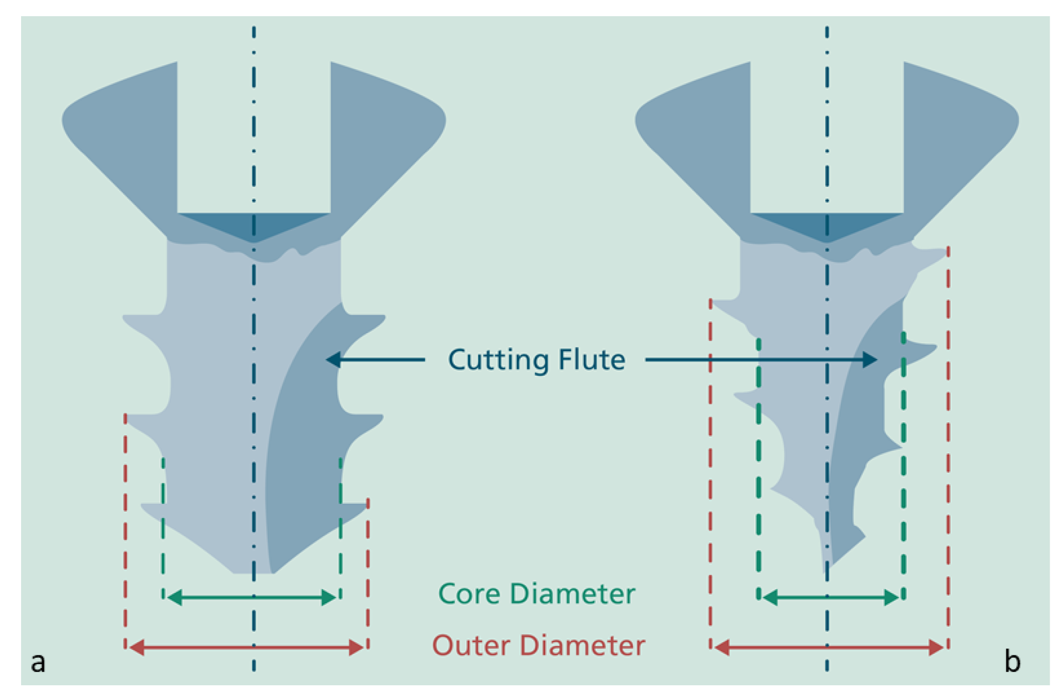
2.1. Investigation of the Splitting Force Induced by Osteosynthesis Screws

A modular test bench, as shown in Figure 3, was developed to investigate the effective splitting forces of self-tapping and self-drilling osteosynthesis screws. The modular design allows an adjustment of the height of the sensors, the length of the screw, and the size of the specimen. Furthermore, the adjustable clamping axis allows adaptation to the width of the specimen.
The test bench was firstly tested with technical materials of bone substitute material (PHACON GmbH, Leipzig, Germany) and a manually driven screwing process with a standard crosshead screwdriver. For the main experiment, porcine cadaver mandibles were selected as a test specimen due to mechanical tissue properties similar to those of human bone. In a standardized process chain for sample preparation of the natural bone material (Fa. Dürrröhrsdorfer Fleisch-und Wurstwaren GmbH, Dürrröhrsdorf, Germany), the specimens were obtained from cadaver mandibles of 6–9 month-old domestic pigs. The mandibles were prepared within 24 h after slaughter and examined for mechanical behavior within 48 h after slaughter. All specimen were stored before and after processing at ~7 °C. First, the soft tissue in the dentition area was removed and the mandibles were separated into slices approximately 2.5 cm in width using a band saw MBS240/E (Proxxon S.A., Wecker, Luxembourg). The resulting bone slices were kept moist in a phosphate-buffered saline solution. In order to investigate the splitting force, the bone slices were warmed up to room temperature (21 °C) and placed centrally in the test bench. The cut surfaces were repositioned and clamped tightly by using threaded fasteners. Subsequently, the screws were screwed in with an angle screw instrument (Angle of the tool axis to the motor axis set at 90°) (Medicon, Tuttlingen, Germany) on the connecting line of the center axes of the installed force sensors and the intersection line of the repositioned cut surfaces, as seen in Figure 4. The rotational speed was set to 100 revolutions per minute, as shown in Table 1, and the feed control of the angled screw instrument was done manually by an experienced surgeon. This methodology was chosen to simulate a realistic screwing scenario with low rotational speeds as used in clinical practice.
In this experimental study, self-tapping and self-drilling screws with a diameter of 2 mm and a length of 9 mm (Anton Hipp GmbH, Fridingen an der Donau, Germany) were compared with regard to their mechanical force application. The exact application parameters and tool or screw specification are listed in Table 1.
Piezoelectric force sensors of type KF26 (Metra Mess- und Frequenztechnik, Radebeul, Germany) and a charge amplifier 5019A (Kistler, Winterthur, Switzerland) were used to convert the splitting force generated by the screwing process into an analog voltage signal. For comparability of the mechanical loads during screw insertion (thrust force and torque) with the load pattern during insertion into uncut full material, the test bench was mounted centrally on a 4-component dynamometer 9272 (Fa. Kistler, Winterthur, Switzerland) and the force-induced charges were converted into an analog voltage signal by means of a charge amplifier 5007 (Fa. Kistler, Winterthur, Switzerland) as well. These analog voltage signals were translated into digital signals via an A/D voltage converter Goldammer USB-basic (Fa. Goldammer Soft- and Hardware Entwicklung GmbH, Wolfsburg, Germany) and transmitted to the connected PC, as shown in Figure 3. Within the used measurement software DIAdem 2018 (NI Instruments, Austin, TX, USA), the recorded signals were translated into corresponding physical quantities using the sensor-specific calibration factors. The sample size was chosen with a repetition number of n = 8. The measured values were evaluated using Origin 2018 (Originlab, Northampton, MA, USA) and statistically analyzed using one-way ANOVA with Holm-Bonferroni correction.

2.2. Temperature Measurement

The wide spread measurement method of infrared thermography is not possible for the investigation of screws, since no direct recording of the inserted screw is possible and the surrounding tissue requires a certain amount of tissue thickness. Because of that, in a further proof-of-concept experiment, a methodology was developed for measuring the thermal behavior during the insertion of self-tapping and self-drilling screws. TSA2 fiber optic temperature sensors (Weidmann Technologies Deutschland GmbH, Dresden, Germany) were used for this investigation due to the measurement principle and the associated small size. The measuring principle, as shown in Figure 5, is based on the physical effect of the temperature-dependent absorption of certain light components of gallium arsenide. At the tip of an optical fiber, a gallium arsenide crystal absorbs the injected light proportionally to the temperature and the transmitted wavelengths of the light are reflected at a mirror surface. These reflected light signals are evaluated by a 4-channel measurement electronics with integrated spectrometers of the type FOTEMPMK (Fa. Weidmann Technologies Deutschland GmbH, Dresden, Germany), which is connected to a PC. The temperature measurement has been triggered by the measurement software Fotemp Assistant 2 (Fa. Weidmann Technologies Deutschland GmbH, Dresden, Germany) and the data have been stored in a table format.
The heat generated by energy conversion during insertion of the self-tapping and self-drilling screws was also investigated on cadaver mandible specimens from 6–9 month-old domestic pigs (Fa. Dürrröhrsdorfer Fleisch-und Wurstwaren GmbH, Dürrröhrsdorf, Germany) at room temperature (21 °C). A spot with prominent cortical bone was selected as the screw-in location to simulate a harsh screwing situation. In order to investigate the resulting temperatures in the screw and the surrounding tissue, four identical TSA2 type sensors with a specially designed rotational coupling were used and fixed at different locations in the test bench. While one sensor was fixed axially in a drilled hole directly behind the screw tip of specially cannulated screws as seen in Figure 6, the other three sensors were placed in the surrounding tissue. Due to technical reasons, the drill holes in the screw were machined with a twist drill with a diameter of 0.7 mm using a sliding headstock automatic lathe (Tsugami Company, Tokyo, Japan). The measuring point of the sensor was located axially at a distance of 3 mm behind the tip of the screw due to geometric reasons. The hole was filled with BWLP 2.0 thermal paste (Bedek, Dinkelsbühl, Germany), with a thermal conductivity coefficient of λ = 0.81 W/(m*K) according to DIN52612, in order to prevent an insulating effect of the air gap. The sensors in the surrounding tissue were inserted into different tissue structures (bone and nerve canal) due to the anatomy of the mandible and with constant distances of 3 mm (secured by drilling template) into specially drilled holes (d = 0.58 mm). Because of natural moisture and the technically induced retention of residual chip material in the drill base of the tissue, sensor contact can be assumed without an air gap. In order to avoid a strong influence by the drilling process, a speed of 100 rpm was also set for the fabrication of the assistance drill holes.
The sample size was planned with a number of repetitions of n = 8 to verify the measurement principle. The measured values were processed with Origin 2018 (Originlab, Northampton, MA, USA) and statistically analyzed using one-way ANOVA with Holm-Bonferroni correction.

3. Results

3.1. Splitting Force Measurement

The measurement signal shown in Figure 7 represents the curve of the digital voltage signals of the thrust force (red), the torque (black), and the splitting forces (blue, green) of a manually screwed standard screw (hand screwdriver without electric drive) into the bone substitute material (PHACON GmbH, Leipzig, Germany) investigated. The load pattern of the thrust force and torque of self-drilling screws (comparable to self-drilling wood screws), which is typical for manual screwing processes, is clearly visible for the manual screwing process (Figure 7). With the rotation of the tool, a thrust force is intuitively applied by the operator to prevent the tool from slipping and to enable a penetration into the material. These force peaks are also paralleled by an increase in the measured splitting forces. When the tool is re-gripped, a drop in the splitting force signal is also evident, resulting on the one hand from the drop in the thrust force and the associated lower compression of penetrating geometrical elements such as the drill tip and the increasing core diameter of the screw, and on the other hand from the quasi-static properties of the measurement chain and a marginal crosstalk of the torque. The curve of the splitting forces also revealed that the absolute value of the splitting forces increases with increasing insertion depth due to the conical shape of the screw. Thus, it has been clearly demonstrated that this tested screw type is a displacing screw and no chip material is carried out of the hole. The test set-up proved to be suitable for the experimental study.
The signal curve in Figure 7 right hand side for screwing with an electrically driven tool also exhibits an increase in thrust force and the absolute splitting forces increase as the screw depth increases. The maximum of the splitting forces was detected within the screw tightening period without further feed. Conclusions about the symmetry of the force input can be drawn from the difference in the signal curves between the splitting force sensors. In some cases, the results of the measurements differed by about 10% of the absolute values. The force transmitted to the surrounding tissue was defined as the mean value of these two signals, so that a force effect of this value in all directional vectors around the screw axis can be assumed as an approximation.
When comparing the mean values of the splitting forces of the different screw types, it became clear that the commercially available self-drilling screw is a displacing screw type. The splitting force could be determined for this screw type with a mean value of about 200 N. The self-tapping screw, on the other hand, introduced about 10 times less splitting force into the surrounding tissue. This difference is highly significant with p < 0.05. An interesting fact is that a comparably high value was already measured during predrilling for the self-tapping screw. No significant difference could be observed between the thrust forces during the splitting force test and the thrust forces during normal screwing procedure (uncut bone specimen), as shown in Figure 8 (right). The preloading of the specimens thus enabled a solid material to be simulated.

3.2. Temperature Measurement

The temperatures were measured in the screw and the bone tissue as planned. Preliminary tests have shown that there is no influence of the nerve tissue detectable. In addition, no relevant heating of the angled screw instrument was observed, so that an influence of a reverse heat transfer from the tool into the screw can be excluded. During the experiments, the handling of the highly sensitive fiber optic sensors proved to be very challenging for the surgeon. Due to the strong cortical bone, the stability of screw running during screw insertion is severely compromised, especially for the self-drilling screws. When the tool slipped off the screw head, the sensors buckled, leading to the breakage of the optical fiber with the GaAs-chip. Due to the cost-intensive sensor technology and integration the temperature measurement was carried out for a sample size of the self-tapping (n = 2) and self-drilling (n = 3) screws. Upon placement and centering of the screw on the screw blade, heating of the screws could already be detected due to the surgeon’s body temperature. To eliminate this heat input, the system was subsequently maintained until it had cooled down to room temperature. Afterwards, processing and recording was started. As a comparison value of the initial temperature, a mean value was generated from the first five values of the recorded data. The maximum temperature was determined for the time of machining and the time until the system was cooled down to room temperature. The resulting temperature differences of the individual measurements were used to calculate an average value for the temperature increase ΔT, which is shown in Figure 9.
The temperature increase in the screw is clearly higher compared to the temperature increase in the bone, which can be considered as negligible. On account of the low number of repetitions of n = 3 or n = 2, it is only possible to describe tendencies at this point. During the measurement process, the temperature curve in the screw sensor showed a physically induced delay in the measurement signal. Subsequently, the temperature rose to the maximum temperature within 2–3 s and after 2 s it dropped again to the reference temperature within 2–3 s. This effect is caused by heat dissipation mainly via the screw-tool connection.

4. Discussion

The mechanisms of failure are diverse in nature and may occur in the short or long term and may also occur after osseointegration has already been successful. It is known that the very high stiffness of implants often shields the bone tissue from the mechanical stimuli required for homeostasis, resulting in increased resorption [27,28]. Conversely, however, it is also known that excessive mechanical stress on bone tissue leads to increased resorption [7,8,9]. Identification of success factors is only possible with detailed knowledge of the surgical processes, the tools used, the implant properties (chemical, mechanical), and the load pattern during and after implant placement (thermal, mechanical). However, this requires a measurement methodology to determine the thermomechanical load on the surrounding tissue immediately after implant insertion. The methods presented in this study are suitable to determine the thermal and the mechanical load input during and after the insertion of self-drilling and self-tapping osteosynthesis screws for oral and maxillofacial surgery in a biomechanical laboratory test. The feed control via surgeon was chosen to simulate a realistic screwing scenario. An automatic feed is usually path-based and thus cannot react accurately to irregularities, as a manual feed control is able to do. Furthermore, due to the free-form surface of the bone specimens, an additional device would be necessary to secure the tool-screw connection in order to prevent the screws from slipping off. However, this kind of connection device would change the process characteristics. Anyway, in the international literature, a high reproducibility of mechanical loads was observed when drilling bones [29], so a validity of this correlation can also be assumed for screwdriving processes of self-drilling screws. Because of the difficult accessibility and availability of human bone, a porcine animal model was chosen for the biomechanical investigations. The bone structure and composition of the porcine mandible is similar to that of human bone, resulting from the omnivorous diet, making the porcine animal model well suited for biomechanical feasibility studies [30]. The bone substance can be considered comparable to bone tissue in the living organism due to the rapid processing and moisturization of the freshly slaughtered cadaver mandibles.
The test bench to measure the induced splitting force proved to be robust and flexible in use during the biomechanical laboratory tests. Both synthetic bone materials and natural bone material could be tested using the test bench. Comparing the axial thrust forces when screwing on the test bench with the axial thrust forces when screwing into unpartitioned bone specimens (solid material), no significant difference could be observed due to the functioning preloading mechanism. The slightly lower mean values of the thrust force when screwing on the split force test bench are therefore comparable and can be harmonized with the values of the solid material by increasing the preload of the specimens. It is noteworthy that even pre-drilling induces a short-time force into the tissue, which is comparable to the splitting force of the self-tapping screw. This force is caused on the one hand by insufficient chip evacuation and compression of the bone chips and on the other hand by insufficient taper of the secondary cutting edges. After removing the drill, the measured splitting force also decreases. The amount of material displacement of the drilling tool that is included in the splitting force would have to be investigated in a separate series of tests. The approximately 10-times-greater splitting force of the self-drilling screws compared with the self-tapping screws constitutes a significant load for the bone. The force induced by the self-drilling screws (200 N) corresponds to a mass of about 20 kg and acts statically on the tissue. This very high value results from the displacing effect of the screw type. In addition, the chips generated by the cutting groove are not carried to the surface by a flute; instead, they are additionally compressed in the space between the screw and the bone tissue. Comparing the measured value of the splitting force with the force values from the literature such as the values (3 N) obtained by Kobayashi et al. [10] where increased resorption was observed, it can definitely be assumed that resorption occurred as a result of the static load of the tested self-drilling screws. Yadav et al. [31] demonstrated significantly greater microdamage to the surrounding bone tissue of the self-drilling screws compared to the self-tapping screws. The significantly higher splitting forces of the tested self-drilling screws confirmed these findings. However, since no histological examination of the specimens was performed, no crack length or other indicators of microdamage could have been measured. This might be taken into account in subsequent studies. The increasing values of the splitting force during screwing with increasing insertion depth is also consistent with the observations of Halldin et al. [11]. Depending on the condition (influenced by diseases) and the density of the bone [32], it can thus be estimated from the biomechanical studies that the self-drilling screws are associated with a higher risk of initial tissue damage and increased bone resorption due to excessive mechanical loads compared to the self-tapping screws. However, the complex interactions in the living mechanism cannot be investigated with this experimental setup and could only be clarified by an animal experiment. Complications would be suspected in the early healing phase, as observed by Bashutski et al. [13].
Determining the temperature directly in the contact zone of the cutting form elements, such as the main cutting edges or the cutting groove, is not possible due to the high mechanical forces involved and the low material thicknesses. Nevertheless, the second experimental set-up presented in this methods paper proved to be suitable for measuring the temperature with a defined distance to tip of the screw. The advantages of the described method is the direct measurement of the temperature near the main heat source with minimized change in overall process characteristics of miniature screws under realistic conditions. However, there are some restrictions. Usually, thermal load inputs are investigated by an indirect measurement. The wide spread measurement method of infrared thermography, however, is not possible for the investigation of screws in the contact zone, since no direct recording of the inserted screw is possible and the surrounding tissue requires a certain amount of tissue thickness. Zipprich et al. [33] solved this problem by placing milled windows at specified insertion depths prior to measurement and making the screw surface of inserted dental implants visible to the camera. However, this methodology requires a certain size of the inserted implants, because the size of the windows influences the screwing process. Increasing the size of the windows means less material is cut during tapping and the frictional contact area between the screw and bone is reduced and with that less heat will be generated. As a result of the small diameters and generally short total lengths, this methodology is considered to be rather unsuitable for temperature measurement when inserting self-drilling and self-tapping osteosynthesis screws. It further can be assumed that such windows would produce a fundamentally different screwing behavior when screwing with self-drilling screws, since the screws would have to displace less material and the generated bone chips would accumulate in the free spaces of the windows. If a metal cutting process with defined cutting edges is taken as a comparison, it is known that most of the cutting heat is dissipated via the chips (approx. 75%) and only a marginal part of the heat is dissipated through the workpiece (approx. 5%) [34]. However, since the investigated screw types do not have a flute to convey the chips this heat cannot be dissipated. Therefore, the metallic screws and the contacted tool in fact dissipate the resulting heat accumulation due to their significantly better heat conduction properties compared to the surrounding bone. The influence of the axial drill hole on the heat flow and heat capacity of the screw is estimated to be very low due to the small volume of the hole. This should be controlled via comparative studies. Consequently, indirect measurement in the tool respectively the screw is recommended instead of indirect measurement by infrared thermography or measurement in the bone. These heat conduction ratios are also evident in the measured values. While a temperature increase of about 15 K could be measured in the rotation axis of the screw for both screw types, an insignificant increase less than 2 K was found in the bone. Due to the low number of replicates, these results can only be understood as tendencies. Nevertheless, these measured values are in conformity with the values known in the literature, e.g., Baumgart et al. [22].
In an early development calculation based on a simplified mesh node model according to Kauschinger and Schröder [35] of the cannulated screw with an inserted temperature sensor, the temperature field when screwing with self-tapping and self-drilling screws was inversely simulated for the contact surface of the screw tip. The results lead to the assumption that temperatures of about 75 °C were generated at the contact surface of the screw tip for a short period of time. Due to the model-related simplifications and assumptions, however, this absolute value is not directly applicable and requires further investigations or model precisions. The low measured temperature elevations in the surrounding bone occur for various reasons. First, the distance of 0.5 mm to the diameter of the screw channel appears to be too large due to the low thermal conductivity of cortical bone and the high thermal conductivity of the screw. The main heat will be transported via the screw and tool instead of the surrounding tissue. This is also confirmed when considering the measured width of the necrotic area during drilling with twist drills by Robles-Linares et al. [36]. Drilling with a cutting speed of vc = 8.5 m/min and a feed rate of fn = 0.2 mm/rev resulted in temperatures of about 62 °C and a maximum depth of the necrotic zone of 50 µm was measured. The temperature increase induced by the self-drilling and self-tapping screws is in a comparable range, so that a low necrotic layer thickness can also be assumed in this case. Thus, the sensor would have to be placed much closer to the outer diameter of the screw channel in order to measure accurately. Unfortunately, this bears the risk of destruction, since tilting of the screw axis cannot be eliminated due to the manual screwing process. Nevertheless, this tilting could be minimized by using modified drilling templates to guide the screws. Furthermore, an improved heat coupling into the sensor by a paste with defined heat conduction properties, which fills up the space between bone and sensor, can cause an increase in the sensitivity. When using bending-sensitive sensors, it is also advisable to integrate an additional mechanical protection mechanism to prevent the screw blade from slipping off the screw head and irreversibly destroying the sensor.
In summary, both methods have been very well established and moreover both methods can actually be combined on one test bench. Based on these results, the data basis can be expanded and the influences of interfering variables can be progressively minimized. In further studies, the developed methods are to be complemented by comparative studies in order to create a more profound knowledge base regarding their limitations. In perspective, the test benches will be used as a basis for the development and optimization of self-cutting and self-drilling implants and will be extended to other relevant processes.

5. Conclusions

The developed methods generated an enormous gain in knowledge regarding the thermomechanical load input of self-drilling and self-tapping screws. The induced splitting force as a previously unquantified parameter could be converted into numerical values. The self-drilling screw type, which is based on the effect of material displacement, induces a splitting force of about 200 N in the surrounding tissue, so that microdamage of the bone and increased resorption during the healing phase can be assumed. The measurement of the temperature in the screw axis as a fundamentally new approach proved to be suitable for estimating the temperature elevation in the contact zone between implant and bone. Slight improvement of this methodology is necessary to avoid optical fiber breakage. Nevertheless, a threshold exceeding the maximum temperature could be detected, so that a thermal influence on the surrounding tissue is suspected. The flexibly selectable sample geometries and materials represent an enormous advantage of this experimental set-up. However, further studies are required to determine threshold values to eliminate the possibility of bone damage and bone resorption due to thermomechanical loads.

Author Contributions

Conceptualization: S.I., A.B.A. and U.T.; data curation, H.M., C.P., A.B.A., D.H. and A.M.; formal analysis, A.B.A., U.T. and A.M.; funding acquisition: A.B.A., G.L., H.M., C.P.; Resources: H.M., C.P. and A.M.; investigation, A.B.A., H.M., C.P. and D.H.; methodology, A.B.A., H.M., C.P. and D.H.; project administration, S.I. and G.L.; validation, A.B.A., H.M., C.P. and D.H.; visualization, A.M. and U.T.; roles/writing—original draft, A.B.A., U.T. and A.M.; writing—review and editing, S.I., G.L.; H.M., and D.H. All authors have read and agreed to the published version of the manuscript.

Funding

The research project was carried out in the framework of the “Zentrales Innovationsprogramm Mittelstand” (ZF4006621). It was supported by the Federal Ministry for Economic Affairs and Energy (BMWi) through the AiF GmbH (Berlin, Germany).

Institutional Review Board Statement

Not applicable.

Informed Consent Statement

Not applicable.

Data Availability Statement

Not applicable.

Acknowledgments

The authors acknowledge the support of Gerhard Hipp (Anton Hipp GmbH, Fridingen, Germany), Burkhard Scholz (EC Europ Coating GmbH, Hohenlockstedt, Germany), and Andreas Nestler in acquiring the funding for the project and the provision of material resources.

Conflicts of Interest

The authors declare no conflict of interest.

References

  1. Neumayer, B. Zeit-Drehmoment-Diagramme selbstschneidender Osteosyntheseschrauben unterschiedlicher Länge bei Abrißversuchen in Aluminium. Laryngo-Rhino-Otologie 1994, 73, 277–281. [Google Scholar] [CrossRef] [PubMed]
  2. Baumgaertel, S.; Razavi, M.R.; Hans, M.G. Mini-implant anchorage for the orthodontic practitioner. Am. J. Orthod. Dentofac. Orthop. 2008, 133, 621–627. [Google Scholar] [CrossRef]
  3. Ellis, E.; McFadden, D.; Simon, P.; Throckmorton, G. Surgical complications with open treatment of mandibular condylar process fractures. J. Oral Maxillofac. Surg. 2000, 58, 950–958. [Google Scholar] [CrossRef] [PubMed]
  4. Schneider, M.; Lauer, G.; Eckelt, U. Surgical treatment of fractures of the mandibular condyle: A comparison of long-term results following different approaches—Functional, axiographical, and radiological findings. J. Cranio-Maxillofac. Surg. 2007, 35, 151–160. [Google Scholar] [CrossRef] [PubMed]
  5. Möhlhenrich, S.C.; Modabber, A.; Steiner, T.; Mitchell, D.A.; Hölzle, F. Heat generation and drill wear during dental implant site preparation: Systematic review. Br. J. Oral Maxillofac. Surg. 2015, 53, 679–689. [Google Scholar] [CrossRef] [PubMed]
  6. Delgado-Ruiz, R.A.; Calvo-Guirado, J.L.; Romanos, G.E. Effects of occlusal forces on the peri-implant-bone interface stability. Periodontology 2000 2019, 81, 179–193. [Google Scholar] [CrossRef] [PubMed]
  7. Noble, B.S.; Peet, N.; Stevens, H.Y.; Brabbs, A.; Mosley, J.R.; Reilly, G.C.; Reeve, J.; Skerry, T.M.; Lanyon, L.E. Mechanical loading: Biphasic osteocyte survival and targeting of osteoclasts for bone destruction in rat cortical bone. Am. J. Physiol. Physiol. 2003, 284, C934–C943. [Google Scholar] [CrossRef] [PubMed] [Green Version]
  8. Verborgt, O.; Gibson, G.J.; Schaffler, M.B. Loss of Osteocyte Integrity in Association with Microdamage and Bone Remodeling After Fatigue In Vivo. J. Bone Miner. Res. 2000, 15, 60–67. [Google Scholar] [CrossRef] [PubMed]
  9. Takano-Yamamoto, T. Osteocyte function under compressive mechanical force. Jpn. Dent. Sci. Rev. 2014, 50, 29–39. [Google Scholar] [CrossRef] [Green Version]
  10. Kobayashi, Y.; Hashimoto, F.; Miyamoto, H.; Kanaoka, K.; Miyazaki-Kawashita, Y.; Nakashima, T.; Shibata, M.; Kobayashi, K.; Kato, Y.; Sakai, H. Force-Induced Osteoclast Apoptosis In Vivo Is Accompanied by Elevation in Transforming Growth Factor β and Osteoprotegerin Expression. J. Bone Miner. Res. 2000, 15, 1924–1934. [Google Scholar] [CrossRef] [PubMed] [Green Version]
  11. Halldin, A.; Jimbo, R.; Johansson, C.B.; Wennerberg, A.; Jacobsson, M.; Albrektsson, T.; Hansson, S. Implant Stability and Bone Remodeling after 3 and 13 Days of Implantation with an Initial Static Strain. Clin. Implant Dent. Relat. Res. 2014, 16, 383–393. [Google Scholar] [CrossRef] [PubMed]
  12. Ikar, M.; Grobecker-Karl, T.; Karl, M.; Steiner, C. Mechanical stress during implant surgery and its effects on marginal bone: A literature review. Quintessence Int. 2019, 51, 2–10. [Google Scholar] [CrossRef]
  13. Bashutski, J.D.; D’Silva, N.J.; Wang, H.-L. Implant Compression Necrosis: Current Understanding and Case Report. J. Periodontol. 2009, 80, 700–704. [Google Scholar] [CrossRef] [PubMed] [Green Version]
  14. Ikumi, N.; Suzawa, T.; Yoshimura, K.; Kamijo, R. Bone Response to Static Compressive Stress at Bone-Implant Interface: A Pilot Study of Critical Static Compressive Stress. Int. J. Oral Maxillofac. Implant. 2015, 30, 827–833. [Google Scholar] [CrossRef] [PubMed] [Green Version]
  15. Blaß, H.J.; Bejtka, I.; Uibel, T. Tragfähigkeit Von Verbindungen Mit Selbstbohrenden Holzschrauben Mit Vollgewinde. In Karlsruher Berichte zum Ingenieurholzbau; Band 4; Universitätsverlag Karlsruhe: Karlsruhe, Germany, 2006. [Google Scholar]
  16. Eriksson, A.; Albrektsson, T.; Grane, B.; McQueen, D. Thermal injury to bone. Int. J. Oral Surg. 1982, 11, 115–121. [Google Scholar] [CrossRef]
  17. Li, S.; Chien, S.; Brånemark, P.I. Heat shock-induced necrosis and apoptosis in osteoblasts. J. Orthop. Res. 1999, 17, 891–899. [Google Scholar] [CrossRef] [PubMed]
  18. Pellicer-Chover, H.; Peñarrocha-Oltra, D.; Aloy-Prosper, A.; Sanchis-Gonzalez, J.; Peñarrocha-Diago, M. Comparison of peri-implant bone loss between conventional drilling with irrigation versus low-speed drilling without irrigation. Med. Oral Patol. Oral Cir. Bucal 2017, 22, e730. [Google Scholar] [CrossRef]
  19. Ben Achour, A.; Petto, C.; Meißner, H.; Hipp, D.; Nestler, A.; Lauer, G.; Teicher, U. The Influence of Thrust Force on the Vitality of Bone Chips Harvested for Autologous Augmentation during Dental Implantation. Materials 2019, 12, 3695. [Google Scholar] [CrossRef] [Green Version]
  20. Oh, J.-H.; Fang, Y.; Jeong, S.-M.; Choi, B.-H. The effect of low-speed drilling without irrigation on heat generation: An experimental study. J. Korean Assoc. Oral Maxillofac. Surg. 2016, 42, 9. [Google Scholar] [CrossRef] [PubMed] [Green Version]
  21. Löhr, J.; Gellrich, N.; Büscher, P.; Wahl, D.; Rahn, B.A. Vergleichende In-vitro-Untersuchungen von selbstbohrenden und selbstschneidenden Schrauben. Mund-Kiefer-und Gesichtschirurgie 2000, 4, 159–163. [Google Scholar] [CrossRef]
  22. Baumgart, F.W.; Cordey, J.; Morikawa, K.; Perren, S.; Rahn, B.; Schavan, R.; Snyder, S. AO/ASIF self-tapping screws (STS). Injury 1993, 24, 1–17. [Google Scholar] [CrossRef]
  23. Ghazali, M.; Roseiro, L.; Garruço, A.; Margalho, L.; Expedito, F. Pre-drilling vs. Self-drilling of Pin Bone Insertion—A Thermography Experimental Evaluation. In VipIMAGE 2017; Tavares, J., Natal Jorge, R., Eds.; Springer International Publishing: Cham, Switzerland, 2018; Volume 27, pp. 1063–1068. [Google Scholar] [CrossRef]
  24. Möhlhenrich, S.C.; Heussen, N.; Modabber, A.; Kniha, K.; Hölzle, F.; Wilmes, B.; Danesh, G.; Szalma, J. Influence of bone density, screw size and surgical procedure on orthodontic mini-implant placement—Part A: Temperature development. Int. J. Oral Maxillofac. Surg. 2021, 50, 555–564. [Google Scholar] [CrossRef] [PubMed]
  25. Matsuoka, M.; Motoyoshi, M.; Sakaguchi, M.; Shinohara, A.; Shigeede, T.; Saito, Y.; Matsuda, M.; Shimizu, N. Friction heat during self-drilling of an orthodontic miniscrew. Int. J. Oral Maxillofac. Surg. 2011, 40, 191–194. [Google Scholar] [CrossRef] [PubMed]
  26. Xu, W. Instrumentation and experiment design for in-vitro interface temperature measurement during the insertion of an orthopaedic implant. In Proceedings of the 10th International Conference on Control, Automation, Robotics and Vision, Hanoi, Vietnam, 1 April 2008; pp. 1773–1778. [Google Scholar] [CrossRef]
  27. Trullenque-Eriksson, A.; Guisado-Moya, B. Retrospective long-term evaluation of dental implants in totally and partially edentulous patients. Part I: Survival and marginal bone loss. Implant Dent. 2014, 23, 732–737. [Google Scholar] [CrossRef] [PubMed]
  28. Cho, S.C.; Small, P.N.; Elian, N.; Tarnow, D. Screw loosening for standard and wide diameter implants in partially edentulous cases: 3- to 7-year longitudinal data. Implant Dent. 2004, 13, 245–250. [Google Scholar] [CrossRef] [PubMed] [Green Version]
  29. Teicher, U.; Ben Achour, A.; Nestler, A.; Brosius, A.; Lauer, G. Process based analysis of manually controlled drilling processes for bone. AIP Conf. Proc. 2018, 1960, 070025. [Google Scholar] [CrossRef]
  30. Aerssens, J.; Boonen, S.; Lowet, G.; Dequeker, J. Interspecies differences in bone composition, density, and quality: Potential implications for in vivo bone research. Endocrinology 1998, 139, 663–670. [Google Scholar] [CrossRef] [PubMed]
  31. Yadav, S.; Upadhyay, M.; Liu, S.; Roberts, E.; Neace, W.P.; Nanda, R. Microdamage of the cortical bone during mini-implant insertion with self-drilling and self-tapping techniques: A randomized controlled trial. Am. J. Orthod. Dentofac. Orthop. 2012, 141, 538–546. [Google Scholar] [CrossRef]
  32. Wright, T.M.; Hayes, W.C. Fracture mechanics parameters for compact bone-Effects of density and specimen thickness. J. Biomech. 1977, 10, 419–430. [Google Scholar] [CrossRef]
  33. Zipprich, H.; Weigl, P.; König, E.; Toderas, A.; Balaban, Ü.; Ratka, C. Heat Generation at the Implant–Bone Interface by Insertion of Ceramic and Titanium Implants. J. Clin. Med. 2019, 8, 1541. [Google Scholar] [CrossRef] [PubMed] [Green Version]
  34. Kronenberg, M. Machining Science and Application—Theory and Practice for Operation and Development of Machining Processes; Pergamon Press: Oxford, NY, USA, 1966; p. 53. [Google Scholar]
  35. Kauschinger, B.; Schroeder, S. Uncertain Parameters in Thermal Machine-Tool Models and Methods to Design their Metrological Adjustment Process. Appl. Mech. Mater. 2015, 794, 379–386. [Google Scholar] [CrossRef]
  36. Robles-Linares, J.A.; Axinte, D.; Liao, Z.; Gameros, A. Machining-induced thermal damage in cortical bone: Necrosis and micro-mechanical integrity. Mater. Des. 2021, 197, 109215. [Google Scholar] [CrossRef]
Figure 1. Typical geometry of self-tapping (a) and drill-free/self-drilling screw (b) used for oral and maxillofacial surgery.
Biomechanics 01 00020 g001
Figure 2. Examples of mini-orthodontic implants ((a): BIOMET mikrofixation and (c): KLS Martin Maxdrive) and self-drilling osteosynthesis screw ((b): Anton Hipp GmbH—Investigated in this study).
Biomechanics 01 00020 g002
Figure 3. Design of a hardware set-up for experimental evaluation of splitting forces (without test specimen).
Biomechanics 01 00020 g003
Figure 4. Screw position in the center line of the sensors.
Biomechanics 01 00020 g004
Figure 5. Principle of fiber optic temperature sensor based on gallium arsenide.
Biomechanics 01 00020 g005
Figure 6. Concept and photography of an axially fixed fiber optic sensor inside of an osteosynthesis screw.
Biomechanics 01 00020 g006
Figure 7. Qualitative progression of the measurement signals of the set-up to determine the intercellular compression forces for (a,b): set-up verification (manual drive) and (c): experimental data (electrical drive).
Biomechanics 01 00020 g007
Figure 8. Measured splitting forces (mean values ± SEM, n = 8) of different screw types and predrilling (a), and measured thrust forces (mean values ± SEM, n = 8) of the compared screw types for normal screwing and screwing at the test bench (b).
Biomechanics 01 00020 g008
Figure 9. Measured temperature elevation (means with ± SEM) of the different measurement points for self-drilling (n = 3) and self-tapping (n = 2) screws.
Biomechanics 01 00020 g009
Table 1. Tool specification and process parameters for the preparation of the test specimen and the screwing.
Saw Blade
SpecificationValueUnits
Tool material12C27® (equivalent to 1.4034/1.4037)
Tool length1065mm
Number of teeth zsaw24
Tooth width b0.4mm
Cutting speed vc_saw44m/min
Feed rate vf_sawManual
Angled screw instrument
Gear ratio13:1
Intra couplingDIN 1390/ISO-DIS 3964
Length Ltool19mm
Angle of attack90°
Screw bladeCross shape/cruciformAnton Hipp GmbH
Diameter pilot drill ddrill1.5mm
Rotational speed n100rpm
Screws
Core diameter (max.) dcore1.35mm
Outer diameter douter2mm
Total Screw length Lscrew9mm
Pitch P0.75mm per round
Screw tip shapeChamferSelf-tapping (STS)
SharpSelf-drilling (SDS)
Publisher’s Note: MDPI stays neutral with regard to jurisdictional claims in published maps and institutional affiliations.

