Article

Self-Powered Dual-Mode Pressure Sensor Based on Porous Triboelectric Nanogenerator for Use in Smart Home System

1
Henan Province Engineering Research Center of Smart Micro-Nano Sensing Technology and Application, School of Physics and Electronics, Henan University, Zhengzhou 450046, China
2
Zhengzhou Railway Vocational and Technical College, Zhengzhou 450000, China
3
Key Laboratory of Artificial Micro, and Nano-Structures of Ministry of Education, School of Physics and Technology, Wuhan University, Wuhan 430072, China
4
School of Mechanics and Safety Engineering, Zhengzhou University, Zhengzhou 450001, China
*
Authors to whom correspondence should be addressed.
These authors contributed equally to this work.
Nanoenergy Adv. 2024, 4(1), 97-109; https://doi.org/10.3390/nanoenergyadv4010005
Submission received: 4 November 2023 / Revised: 17 January 2024 / Accepted: 18 January 2024 / Published: 4 February 2024

Abstract

:
With the rapid evolution of the Internet of Things (IoT), smart home systems have greatly improved people’s lifestyles and quality of life. However, smart home systems based on a single sensor cannot efficiently control multiple terminals, which limits product penetration into lower-end markets. Here, we have developed a dual-mode smart home system based on a porous triboelectric nanogenerator (TENG), which effectively compensates for the shortcomings of smart home systems being unable to control multiple appliances through a single switch. Benefitting from the remarkable electronegativity of MXene and the ameliorative specific surface area of the friction layer, the output characteristics of the porous TENG are greatly improved. Under the identical external stimulus, the open-circuit voltage (VOC) and short-circuit current (ISC) of the porous TENG were 3.03 and 3.04 times higher than those of the TENG with a pure PVDF membrane used as the friction layer. Thanks to the excellent output performance and good linear relationship between pressure and voltage, the developed dual-mode smart home system could efficiently control multiple terminals through a single sensor. This work not only provides theoretical support for developing high-performance TENGs but also paves the way to designing multifunctional smart home systems.

Graphical Abstract

1. Introduction

With the rapid development of the Internet of Things (IoT), smart home systems have been considered a potential game changer for ameliorating people’s lifestyles and quality of life [1,2,3]. The human-machine interactive sensors with low cost, long-term stability, and high sensitivity play a key role in the connection between electronics and humans [4]. Traditional sensors usually require battery power, which is not conducive to the large-scale layout of smart homes and the IoT [5]. Meanwhile, the use of batteries has obvious drawbacks, such as complex replacement, environmental hazards, and the inability to continuously provide wireless power to devices [6,7]. In this case, the self-powered sensors that can efficiently work without an external power source through harvesting ambient high-entropy energy, emerge as a highly promising human-machine interactive hub [8,9].
Triboelectric nanogenerators (TENG) based on triboelectrification and electrostatic induction, as a rising energy-harvesting technology, have aroused wide attention due to the high electrical output, simple and economical preparation process, and environment friendliness [10,11]. Therefore, self-powered sensors based on TENG are ideal candidates for developing smart home controls [12]. Very recently, significant progress has been made in smart home systems based on self-powered sensors in the last few years. Pandey et al. designed a novel self-powered human-machine interface for a smart control system using Nafion-functionalized barium titanate nanoparticles (BaTiO3 NPs)/PVDF composite nanofibers-based TENG [2]. Gao et al. designed a performance enhanced TENG for self-powered sensing and smart home systems [13]. Zhang et al. designed a hybrid device based on TENG, offering a credible pathway for developing a comfortable self-powered smart home system which contributes to providing humans with a safer and more convenient lifestyle [14]. Shi et al. designed a natural wood-based self-powered sensor based on TENG for building the smart home system, which can remotely control household appliances and software [15]. Although the above studies have their features, it is still impossible to avoid the one-to-one correspondence between sensors and home appliances. There is no doubt that this working mode increases the cost of smart home systems and hinders product penetration into lower-end markets in the smart home field.
In this work, we designed a smart home system based on a dual-mode self-powered pressure sensor, overcoming the one-to-one correspondence between sensors and household appliances, and successfully controlled multiple appliances remotely through a single sensor. The high electronegativity of MXene and the ameliorative specific surface area of the friction layer improved the output performance of TENG, which was verified by Kelvin probe force microscopy (KPFM) and finite element analysis. The optimized VOC and ISC of the porous TENG are up to 607 V and 6.7 μA under a vertical pressure of 2 kPa at 1 Hz, respectively. The optimized VOC and ISC are 3.03 and 3.04 times higher than those of the TENG with a pure PVDF membrane used as the friction layer under the identical external stimulus. Due to its enhanced output performance and good linear relationship between pressure and output voltage, the developed dual-mode smart home system based on a porous TENG can control multiple household appliances through two different working modes.

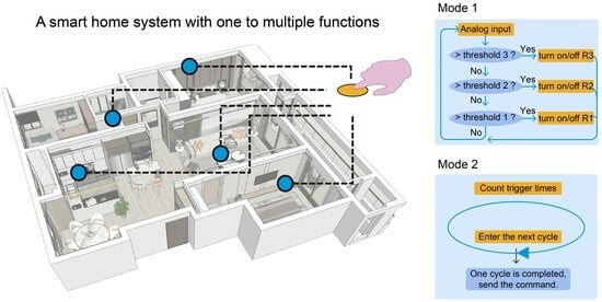
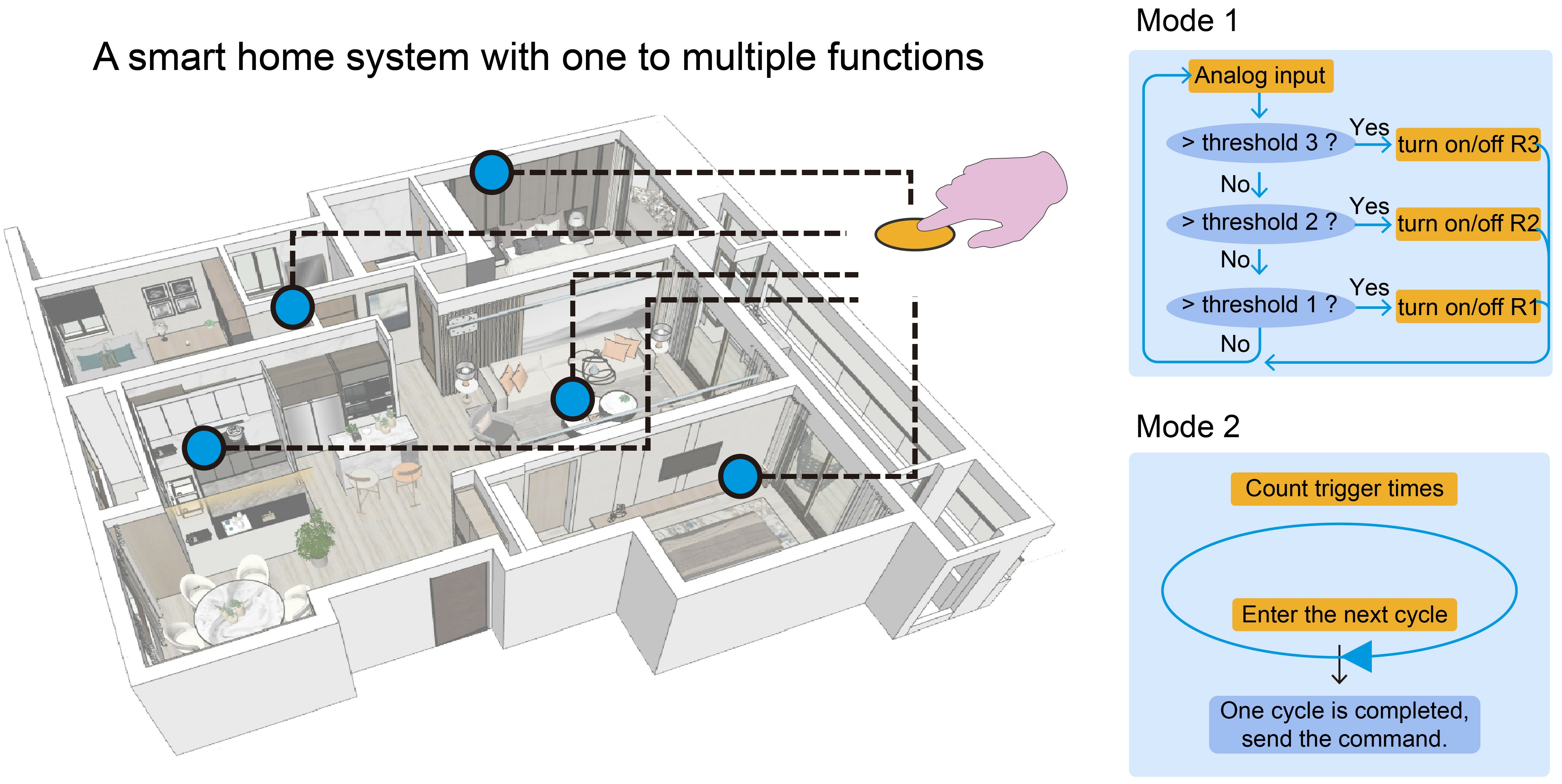
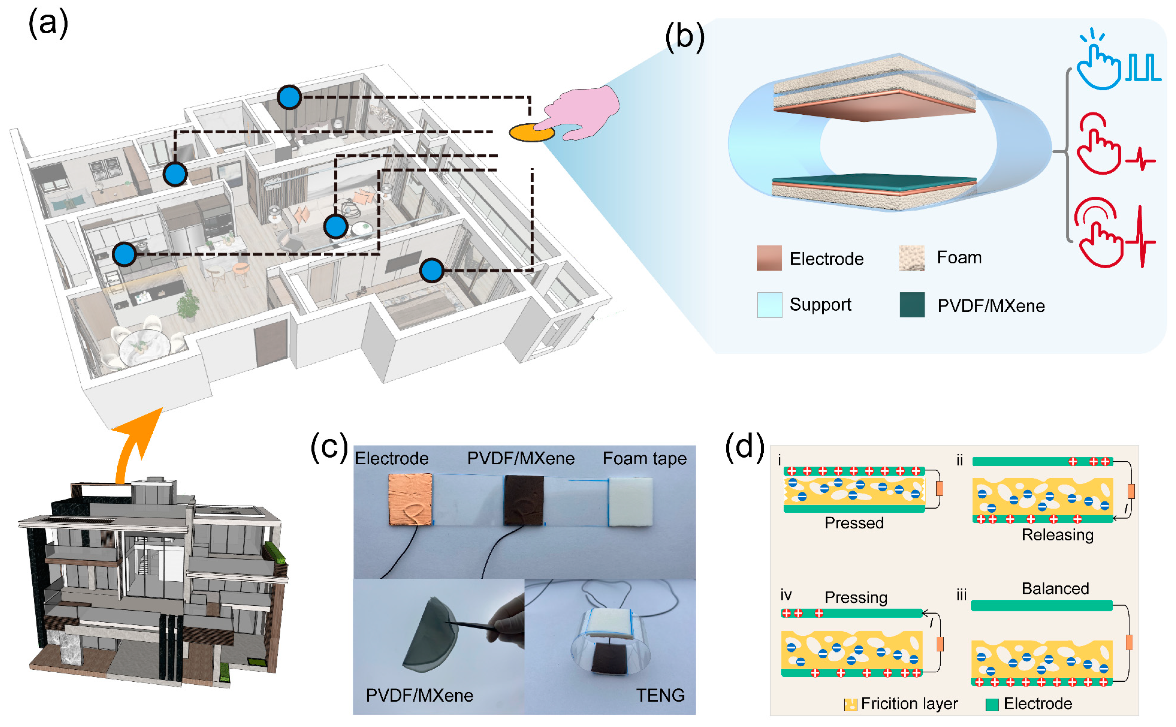
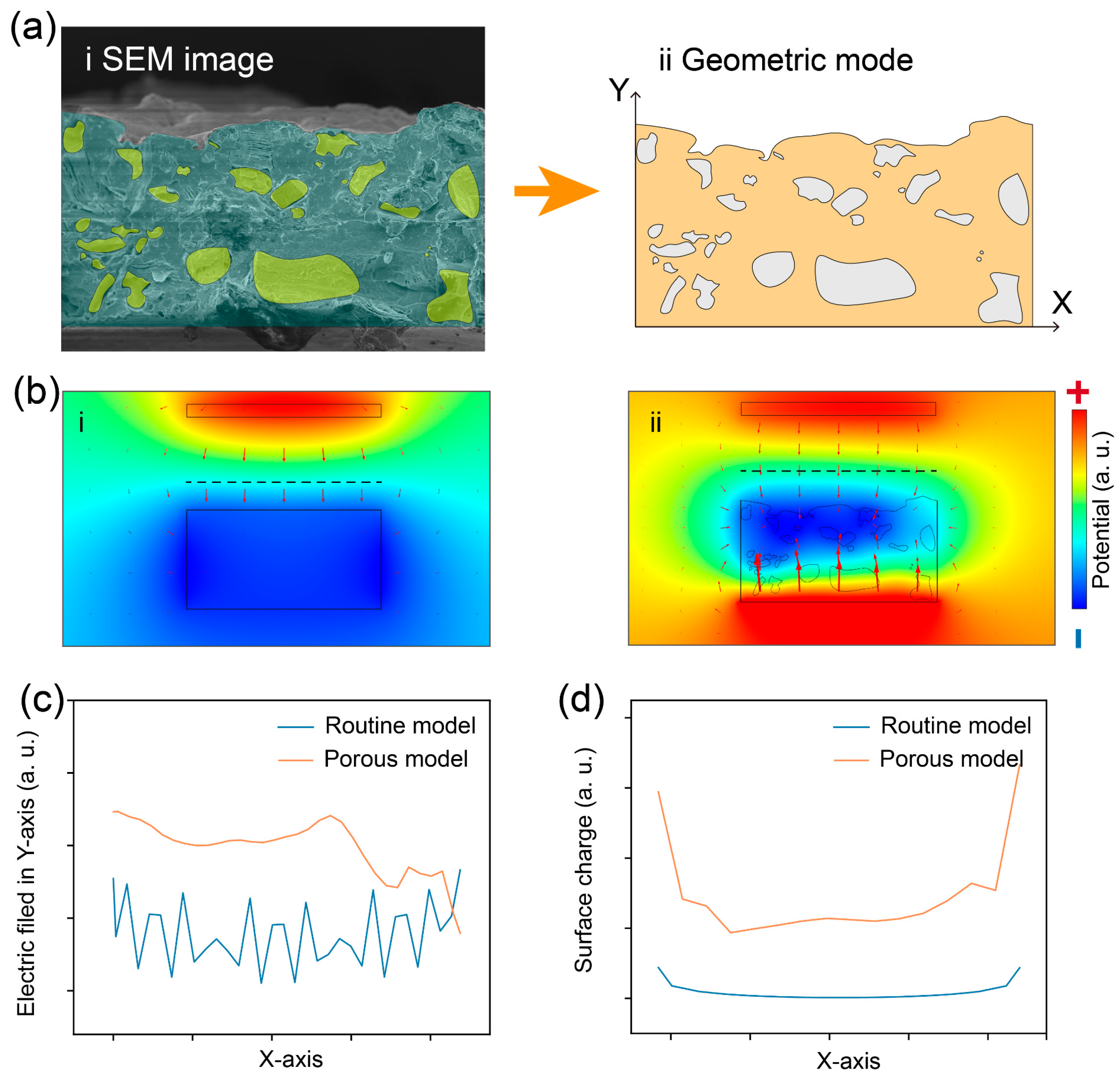
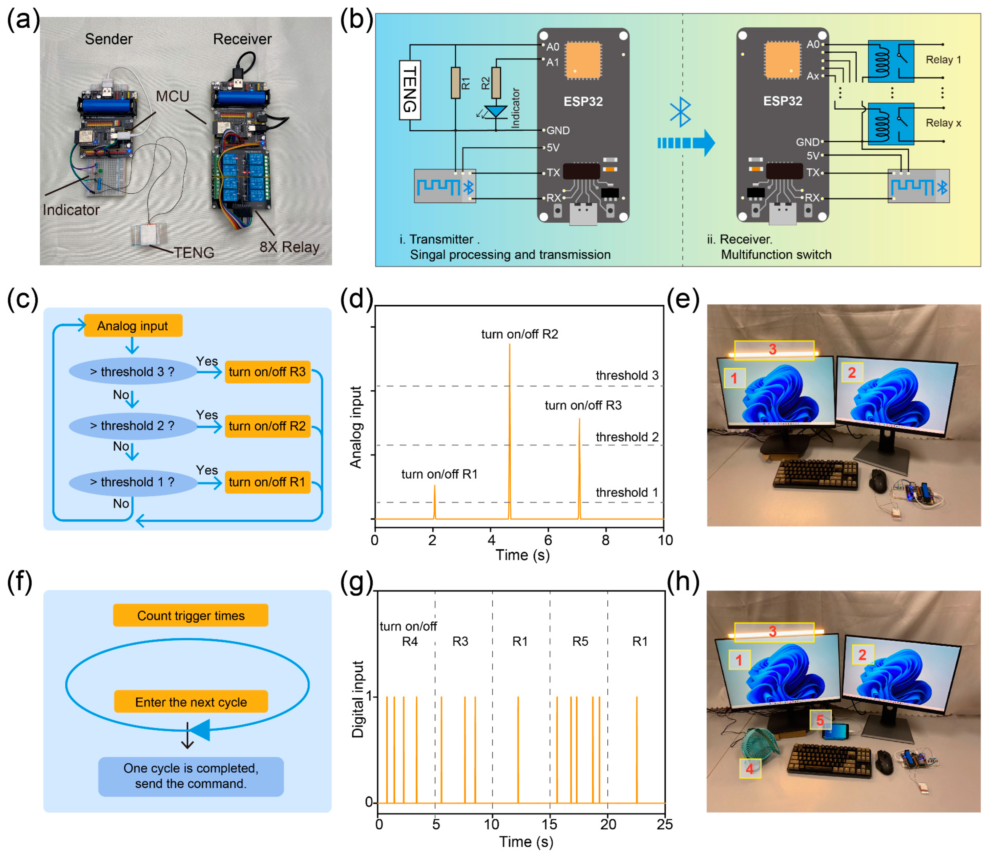
2. Results and Discussion

Figure 1a shows the Structure schematic of the smart home system based on the TENG. Figure 1b elaborates on the 3D structure of the TENG that works in the contact-separation mode and uses a porous PVDF/MXene membrane acting as the primary friction layer. Figure 1c gives optical images of the TENG and porous PVDF/MXene membrane, where the porous PVDF/MXene membrane exhibits good flexibility. In addition, Figure S1 details the fabrication process of the TENG. Figure 1d shows the electrical signal generation process of the PVDF/MXene-based TENG. When the PVDF/MXene friction layer contacts the copper under the pressed state, both are negatively charged and positively charged owing to the triboelectrification effect, respectively, as shown in state i of Figure 1d [16,17]. It is important to note that the porous friction layer exhibits stronger charge storage capacity as a result of the larger effective contact area [18,19]. Improvement of TENG output performance by a large contact area is more obvious in the presence of charge accumulation [20]. Then, once the pressure is released, the positive charges gathered on the top copper electrode will migrate to the bottom Cu electrode through the external circuit to shield against the local electric field (state ii of Figure 1d) [21,22]. When TENG fully returns to its balanced state, all positive charges will concentrate in the bottom Cu electrode thanks to the electrostatic induction, as revealed in state iii of Figure 1d. As the pressure is repeatedly applied, all positive charges will flow to the top Cu electrode again, as shown in state iv of Figure 1d. Eventually, an AC electrical signal is produced in an external circuit with pressure applied to TENG continuously [23,24].
Since the porous structure is more easily compressed by external forces, the TENG makes deeper contact between the electrode and the friction layer when it receives pressure, resulting in a much larger overall contact area [25]. In addition, PVDF/MXene membranes have more F atoms on their surface, making them more conducive to generating a large number of frictional charges during contact electrification [26,27]. These two factors contribute to the output performance of the TENG, which will be discussed in detail below.
Figure 2a shows the XRD spectra of the pure PVDF and PVDF/MXene friction layers with characteristic diffraction peaks at 2θ range from 10° to 60°, with peaks at 17.8° and 20.6° in the (100) and (200) planes corresponding to the α- and β-phases of PVDF, respectively [28]. Figure S2 reveals the XRD spectra of the Ti3C2Tx Mxene is consistent with previous reports, where the (002) peaks around 10° degrees, demonstrating the high ordering of the lamellar stacking [29]. All diffraction peaks in the Figure 2a are derived from both PVDF and MXene [30]. Figure 2b gives the XPS results for the PVDF/MXene friction layers and pure PVDF. MXene materials contain abundant fluorine (F) elements that have strong electronegativity, which will promote the production of triboelectric charges [27,31]. Therefore, it is necessary to study the content of the F element in different PVDF/MXene membranes. In this work, the MAX phase raw material was etched by hydrogen fluoride (HF), resulting in the F atoms acting as the terminated group in the MXene structure. As indicated in Figure 2c, the content of the F element increases with the increase of the MXene content in the membranes, indicating the addition of the MXene will improve the performance of the TENG by increasing the triboelectric charges [8]. The dielectric constants (εr) of the as-resulted PVDF/Mxene friction layers are shown in Figure 2d. It is clear to see that the εr value of the friction layer increases with increasing MXene content. Previous reports have confirmed that the trapping ability and charge transfer is proportional to the dielectric constant of the friction layer, and therefore, the incorporation of MXene into the composite film is expected to enhance the output characteristics of the TENG [21,32]. The εr value of all the samples decreased with the increase of test frequency because of the confinement of dipoles and ionic migration at high frequencies [16,33]. Figure 2e shows that the dielectric loss of the sample also increases with the increase of MXene content, which may be detrimental to the output characteristics of TENGs. To increase the triboelectric charge on the surface of the PVDF/MXene friction layer, NaCl particles have been added during the sample preparation process. After the composite film solidifies, NaCl is removed by soaking and voids are left. The specific surface areas of different samples are shown in Figure 2f. It is evident that as the NaCl content increases, the specific surface area of the sample also gradually increases. Figure 2g and Figure S3 present the SEM images of the PVDF/MXene friction layer with different specific surface areas. As indicated in Figure 2h, to display the MXene in the film more clearly, the PVDF and MXene were marked by cyan and orange, respectively. Figure 2i shows the EDS mapping for C, O, F, and Ti elements in the porous PVDF/MXene friction layer.
By introducing a large amount of the F element, the surface electronegativity of the friction layer will undergo significant changes, which will greatly affect the transfer behavior of frictional charges [34].
In order to gain a deeper understanding of the key factors affecting the output characteristics of the TENG, the contact potential differences (CPD) between the PVDF/MXene friction layers and the tip have been measured using the KPFM, as manifested in Figure 2j. Figure S4 lists the CPD test results of different samples, indicating that the CPD of the friction layer increases with the MXene content; an increase owing to the introduction of the F element. The effective work function (φeff) of PVDF/Mxene membranes can be calculated by the following equation [35,36]
φ eff   =   φ tip   CPD   ×   e
where φtip represents the work function of the tip used in the KPFM test. The inset of state iv in Figure 2j records the φeff for PVDF/MXene friction layers. The φeff of the sample gradually increases with the increase of the F element content due to the F elements having strong electronegativity. The φeff of the friction layer has a crucial effect in the triboelectrification process, which is explained in detail in Figure 2k using the band-structure model.
Previous reports have shown that when two materials are in contact, electrons are preferentially transferred to the material with the lower surface energy state until an equilibrium energy state is eventually formed [37]. In general, the surface energy state of a material is positively correlated with its work function, and the work function for copper (W1) is usually lower than that for dielectric materials (W2) [38,39]. Therefore, when the copper electrode and the PVDF/MXene friction layer are in contact, triboelectric charges flow from the copper electrode to the PVDF/MXene friction layer, as shown in state i in Figure 2k [40]. The quantity of charge transferred in this process can be calculated by the following equation:
σ = e E d E m N ( E ) d E
where Em is the Fermi level of the metal, N(E) is the surface state density, E0 is the highest occupied surface state level of the pVDF/MXene friction layer. It is apparent that the amount of charge transferred during triboelectrifrication process is proportional to the effective work function of the friction layer, as revealed in state ii in Figure 2k.
To systematically study the impact of MXene on the output characteristics of the TENG, we prepared the TENG using friction layers with different MXene contents and measuring the VOC and ISC under a fixed pressure of 2 kPa, as shown in Figure 3a,b. At 30% MXene content, the maximum VOC and ISC of the TENG were 200 V and 2.2 μA, respectively, which could be attributed to the fact that the εr of the PVDF/MXene friction layer and the φeff difference with the electrodes increased with the increase of the MXene content, which facilitated the charge storage and transfer behaviors as shown in Figure 2j. Nevertheless, the VOC and ISC decrease when the MXene content is 40%, owing to the air breakdown phenomenon. The dependence of output characteristics of the TENG using a composite membrane with an MXene content of 30% on external load resistance are plotted in Figure 3c and Figure S5. The instantaneous output power density of the TENG can be calculated by the equation [32]:
P = U I S
where, U, I, and S are the output voltage, output current, and effective area, respectively. The maximum instantaneous output power density can reach 37.4 µW cm−2 at a load resistance of about 13 MΩ.
In addition, to investigate the effect of a specific surface area on TENG output characteristics, we prepared the TENG using a porous PVDF/Mxene with different specific surface areas and conducted tests, and detailed results are recorded in Figure 3d,e. It should be noted that the MXene content of the TENG used in this test is 30%. The porous TENG exhibits optimal output performance when the NaCl content is 15% (the specific surface area is 78 m2 g−1), where the VOC is 607 V and ISC is 6.7 μA. The increase in specific surface area can be approximated as an increase in the effective contact area of the TENG during contact separation, resulting in improved output performance. However, when the NaCl content is too high, the quality of the friction layer deteriorates, thereby reducing the output performance. Meanwhile, the maximum instantaneous output power density of the optimal porous TENG can reach 86.4 µW cm−2 at a load resistance of about 10 MΩ, as illustrated in Figure 3f and Figure S6. The above results prove that the addition of Mxene and increasing the specific surface area of the friction layer are beneficial for improving the output performance of the TENG. In addition, we examined the effect of ambient temperature and humidity on the TENG output performance, as shown in Figure S7. The TENG performance degraded as the room temperature increased, because the thermal fluctuation lowers the net negative charges on the friction layer surface and reduces the output, as shown in Figure S7a. The humidity dependence on the device performance was investigated in Figure S7b. The VOC degraded as the environment humidified. This is because as the humidity in the environment increased, more water in the environment was adsorbed onto the friction layer surface, preventing the charge transfer between the two contacted surfaces and leading to the degraded outputs increasing, as revealed in Figure S7b.
In order to optimize the experimental results, we have selected the friction layer with the MXene and NaCl content of 30 wt% and 15 wt% to conduct follow-up research, respectively. The voltage of different capacitors charged by the porous TENG operated under hand slapping is recorded in Figure 3g. The inset of Figure 3g is the enlarged view of the charging curve for the 1 µF capacitor. Figure S8 shows the energy harvesting based on the porous TENG and corresponding circuit diagrammatic. Besides, the mechanical stability of the porous TENG was tested at a frequency of 1 Hz and a pressure of 2 kPa. As drawn in Figure 3h, there is no significant decrease in VOC after about 7100 cycles. Interestingly, the VOC of the TENG exhibits a good linear relationship with the received pressure as shown in Figure 3i. The relative linear correlation coefficient between the VOC and the received pressure is as high as 0.997, indicating the excellent sensing performance of the porous TENG. The excellent pressure-voltage response relationship may be attributed to the fact that porous film produces more significant depressions when subjected to external stimuli, thus increasing the effective contact area during friction [25,41]. Besides, the response time can reach 4.9 ms, as indicated in Figure S9. The above results indicate that the porous TENG features excellent mechanical durability and response time, laying the foundation for subsequent sensing testing.
To further understand the contribution of porous friction layers to TENG output performance, we systematically analyzed the electrical parameters of two different models using finite element analysis. The porous model was constructed from SEM images, as shown in Figure 4a. Figure 4b reveals the simulation results of the electric field and potential distribution using two models, indicated by red arrows and different colors, respectively. It can be seen that compared to routine models, the electric field strength and potential between the electrode and friction layer in the porous model are stronger.
To intuitively analyze the electric field strength and surface charge distribution in the two models, a more in-depth comparison of the data based on the above simulation results was performed, as presented in Figure 4c,d. Figure 4c plots the electric field strength along the dashed line in Figure 4b, indicating the electric field strength between electrode and friction and electrode in the porous model is stronger than that of the routine model. The reason for this phenomenon can be traced back to the larger effective area of the porous friction layer, which has more surface charges [42]. According to the principle of capacitors, when the distance between the electrode and the friction layer is the same, the more surface charges there are, the stronger the induced electric field [43,44]. In addition, Figure 4d gives the surface charge distribution of the bottom surface in the electrode for the two models. As expected, the results shown in Figure 4c also demonstrate that more charges accumulate on the electrodes of the porous model. In summary, the finite element analysis results demonstrate that the porous friction layer increases the amount of surface charge due to its larger effective area. Therefore, the output performance of the porous TENG has been improved. More importantly, the simulation results in Figure 4 agree well with the experimental results in Figure 3.
Benefiting from the excellent mechanical durability and response time, a smart home system based on a porous TENG has been constructed. Figure 5a presents the image of the smart home system, which consists of an MCU, porous TENG, relay, and bluetooth module. Figure 5b shows the system architecture of the smart home system, where the porous TENG acts as a sensing unit for detecting external pressure and converting mechanical stimuli into electrical signals. Then the electrical signals are sampled by the MCU and the command is transmitted to the receiver through the bluetooth module. It is worth noting that R1 is much smaller than the internal resistance of the TENG, so connecting R1 in parallel can effectively reduce the voltage signal captured by port A0. In addition, the pulse width of the voltage output signal of the TENG is very small, about 10 ms (Figure S9), thus greatly reducing the possibility of MCU damage. Due to excellent output performance and the good pressure-voltage linear relationship of the porous TENG, smart home systems can operate in two different modes, which have never been studied in previous reports.
The experimental results in Figure 3i show that the output voltage of the TENG is linearly correlated with the pressure received. Therefore, mode 1 of the smart home system sends different commands by comparing the harvested voltage signals with different thresholds. In mode 1, the set program classifies the collected signals based on their amplitude and compares them with different thresholds. Different thresholds correspond to different commands, so the working status of different appliances can be wirelessly controlled by controlling the magnitude of the force when touching the TENG. The detailed program schematic diagram for mode 1 is revealed in Figure 5c. The analog signals collected by the MCU are recorded in Figure 5d. Figure 5e illustrates the image of the smart home system working in mode 1, where two computers and a light are controlled by the smart home system. When tapping the TENG with different forces, different electrical appliances can be controlled. The detailed demonstration video is shown in Video S1.
Generally, people cannot accurately control the strength of their hands when tapping, so only three thresholds are set in mode 1; that is, mode 1 can only control three appliances [21,45]. To make up for this deficiency, we have developed mode 2. The MCU sends different instructions by counting the number of TENG electrical outputs within a cycle, and the corresponding schematic is shown in Figure 5f. In mode 2, the output signal of the porous TENG is collected by the MCU and converted to a digital signal instead of the analog signal, as shown in Figure 5g. In this mode, the smart home system can easily control multiple appliances, as presented in Figure 5h. The detailed demonstration video is shown in Video S2.

3. Conclusions

In this work, we utilized the large electronegativity of the MXene and the large specific surface area of the friction layer to improve the output performance of the TENG, and verified by KPFM and finite element analysis. The optimized VOC and ISC of the porous TENG are up to 607 V and 6.7 μA under a vertical pressure of 2 kPa at 1 Hz, respectively, when the mass fraction of the MXene and NaCl were 30 wt% and 15 wt%, respectively. The optimized VOC and ISC are 3.03 and 3.04 times higher than those of the TENG with a pure PVDF membrane used as the friction layer under the identical external stimulus. Thanks to the TENG’s excellent output performance and good linear relationship between pressure and voltage, we have developed a dual-mode smart home system, which effectively compensates for the previously reported shortcomings of smart home systems being unable to control multiple appliances through a single device. This work not only provides new ideas for designing high-performance TENGs, but also provides a paradigm for developing economical and efficient smart home systems.

4. Experimental Section

Fabrication of porous TENG: Ti3AlC2 MAX phase raw material was purchased from Sigma-Aldrich. MXene was fabricated by selective etching of aluminum layers using HF. An appropriate amount of MAX phase raw material was added to the etchant and continuous stirring at 600 rpm for 24 h at 40 °C. The solution was repeatedly washed with DI water through a centrifuge. When the pH rises to 6, the centrifugation time is set to 1 h. Finally, adjust the temperature of the vacuum drying oven to 120 C to dry the sample for 30 h.
N,N-dimethylformamide (DMF, 99.7%,) purchased from Sinopharm Co., Ltd. (Shanghai, China). PVDF was purchased from Dongguan Kaifeng Co. Ltd. (Dongguan, China) The PVDF/MXene friction layer is prepared by spin coating method. Dissolve PVDF powder and different masses of MXene in DMF solution to prepare PVDF/MXene solution, where the mass of PVDF and the volume of DMF are 0.8 g and 4 mL, respectively. Then stir the solution with a magnetic stirrer at a temperature of 50 °C for 4 h to obtain a uniform precursor solution. The spin coating process is divided into two stages. The first stage lasts for 10 s at a speed of 500 rpm, and the second stage lasts for 20 s at a speed of 850 rpm, and the third stage is cured at 90 °C for 10 min. Finally, PVDF/MXene and copper tape act as the friction layer and electrode, respectively.
Measurement of the samples: The surface morphology of samples was characterized by SEM (ZEISS-SIGMA). Before conducting SEM testing on the sample, a gold coating needs to be prepared using sputtering equipment (KYKY, SBC-12, Zhongkekeyi, Beijing, China). During this process, the air pressure, current, and duration are 7 Pa, 7 mA, and 60 s, respectively. The X-ray diffraction (XRD, Bruker D8, Bruker, Billerica, MA, USA) is used to analyze the crystal structure of the samples. Electrical output signals were obtained by an oscilloscope (TDS2012B, Tektronic, Beaverton, OR, USA) and an electrometer (Keithley 6514, Tektronic, Beaverton, MA, USA), respectively. The specific surface areas of the PVDF/MXene were measured by the BET method using a TriStar II (TriStar II 3020 V1.03, Micromeritics, Norcross, GA, USA). The dielectric constant and dielectric loss of samples were measured by an LCR meter (TZDM-RT-1000, Julang, Harbin, China). The surface potential of the PVDF/MXene friction layers was obtained by Kelvin probe force microscope (MFP-3D Origin Plus, Asylum Research, Santa Barbara, CA, USA).

Supplementary Materials

The following supporting information can be downloaded at: https://www.mdpi.com/article/10.3390/nanoenergyadv4010005/s1, Figure S1. Production process of TENG; Figure S2. XRD result of the Ti3C2Tx-M; Figure S3. (a) Surface SEM image of the PVDF/MXene membrane. (b,c) SEM images of the PVDF/MXene membranes after adding different contents of NaCl and dissolving them; Figure S4. Contact potential difference for PVDF/MXene membranes with the different mass fractions of MXene; Figure S5. Variation of the output current of the TENG on the external load resistance; Figure S6. Variation of the output current of the porous TENG on the external load resistance; Figure S7. Effect of (a) room temperature and (b) humidity on VOC of the TENG. Figure S8. Photo for the energy harvesting based on the porous TENG and corresponding circuit diagrammatic; Figure S9. Enlarged view of the output voltage signal for determining the response time; Video S1: Demonstration for Smart home system working in mode 1; Video S2: Demonstration for Smart home system working in mode 2.

Author Contributions

Y.Z.: conceptualization, visualization, validation, formal analysis, data curation, writing—original draft preparation. J.C.: visualization, validation, formal analysis, writing—review and editing. Y.M.: visualization, validation, formal analysis. H.W.: validation, formal analysis. J.H.: validation, formal analysis. X.G.: visualization, validation, formal analysis. S.G.: supervision, project administration. H.Z.: writing—review and editing, supervision, project administration, funding acquisition. All authors have read and agreed to the published version of the manuscript.

Funding

The authors gratefully acknowledge support from the National Natural Science Foundation of China (Nos. 52072111 and 62374119) and the China Postdoctoral Science Foundation (2023M740992).

Data Availability Statement

The original contributions presented in the study are included in the article/supplementary material, further inquiries can be directed to the corresponding author/s.

Conflicts of Interest

The authors declare no conflicts of interest.

References

  1. Hao, S.; Jiao, J.; Chen, Y.; Wang, Z.L.; Cao, X. Natural wood-based triboelectric nanogenerator as self-powered sensing for smart homes and floors. Nano Energy 2020, 75, 104957. [Google Scholar] [CrossRef]
  2. Pandey, P.; Jung, D.-H.; Choi, G.-J.; Seo, M.-K.; Lee, S.; Kim, J.M.; Park, I.-K.; Sohn, J.I. Nafion-mediated barium titanate-polymer composite nanofibers-based triboelectric nanogenerator for self-powered smart street and home control system. Nano Energy 2023, 107, 108134. [Google Scholar] [CrossRef]
  3. Zhang, Y.; Gao, X.; Wu, Y.; Gui, J.; Guo, S.; Zheng, H.; Wang, Z.L. Self-powered technology based on nanogenerators for biomedical applications. Exploration 2021, 1, 90–114. [Google Scholar] [CrossRef]
  4. Song, Y.; Mukasa, D.; Zhang, H.; Gao, W. Self-powered wearable biosensors. Acc. Mater. Res. 2021, 2, 184–197. [Google Scholar] [CrossRef]
  5. Wang, X.; Feng, Z.; Xia, Y.; Zhang, G.; Wang, L.; Chen, L.; Wu, Y.; Yang, J.; Wang, Z.L. Flexible pressure sensor for high-precision measurement of epidermal arterial pulse. Nano Energy 2022, 102, 107710. [Google Scholar] [CrossRef]
  6. Shipra, S.; Akhilesh, K.; Udiptya, S.; Alexey, V.; Rajinder, K.; Bansi, D. Triboelectric Nanogenerator-based smart biomedical sensors for healthcare. Sustain. Energy. Technol. 2023, 57, 103233. [Google Scholar]
  7. An, S.; Pu, X.; Zhou, Y.; Wu, Y.; Li, G.; Xing, P.; Zhang, Y.; Hu, C. Deep Learning Enabled Neck Motion Detection Using a Triboelectric Nanogenerator. ACS Nano 2022, 16, 9359–9367. [Google Scholar] [CrossRef]
  8. Luo, X.; Liu, L.; Wang, Y.C.; Li, J.; Berbille, A.; Zhu, L.; Wang, Z.L. Tribovoltaic nanogenerators based on MXene-silicon heterojunctions for highly stable self-powered speed, displacement, tension, oscillation angle, and vibration sensors. Adv. Funct. Mater. 2022, 32, 2113149. [Google Scholar] [CrossRef]
  9. Salauddin, M.; Rana, S.M.S.; Rahman, M.T.; Sharifuzzaman, M.; Maharjan, P.; Bhatta, T.; Cho, H.; Lee, S.H.; Park, C.; Shrestha, K.; et al. Fabric-Assisted MXene/silicone nanocomposite-based triboelectric nanogenerators for self-powered sensors and wearable electronics. Adv. Funct. Mater. 2021, 32, 2107143. [Google Scholar] [CrossRef]
  10. He, W.; Shan, C.; Fu, S.; Wu, H.; Wang, J.; Mu, Q.; Li, G.; Hu, C. Large harvested energy by self-excited liquid suspension triboelectric nanogenerator with optimized charge transportation behavior. Adv. Mater. 2022, 35, e2209657. [Google Scholar] [CrossRef]
  11. Lu, C.; Wang, X.; Shen, Y.; Wang, C.; Wang, J.; Yong, Q.; Chu, F. Liquid-free, anti-freezing, solvent-resistant, cellulose-derived ionic conductive elastomer for stretchable wearable electronics and triboelectric nanogenerators. Adv. Funct. Mater. 2022, 32, 2207714. [Google Scholar] [CrossRef]
  12. Yang, J.; Liu, S.; Meng, Y.; Xu, W.; Liu, S.; Jia, L.; Chen, G.; Qin, Y.; Han, M.; Li, X. Self-powered tactile sensor for gesture recognition using deep learning algorithms. ACS Appl. Mater. Interfaces 2022, 14, 25629–25637. [Google Scholar] [CrossRef] [PubMed]
  13. Gao, L.; Hu, D.; Qi, M.; Gong, J.; Zhou, H.; Chen, X.; Chen, J.; Cai, J.; Wu, L.; Hu, N.; et al. A double-helix-structured triboelectric nanogenerator enhanced with positive charge traps for self-powered temperature sensing and smart-home control systems. Nanoscale 2018, 10, 19781–19790. [Google Scholar] [CrossRef] [PubMed]
  14. Zhang, H.; Yin, F.; Shang, S.; Li, Y.; Qiu, Z.; Lin, Q.; Wei, X.; Li, S.; Kim, N.Y.; Shen, G. A high-performance, biocompatible, and degradable piezoresistive-triboelectric hybrid device for cross-scale human activities monitoring and self-powered smart home system. Nano Energy 2022, 102, 107687. [Google Scholar] [CrossRef]
  15. Shi, X.; Luo, J.; Luo, J.; Li, X.; Han, K.; Li, D.; Cao, X.; Wang, Z.L. Flexible wood-based triboelectric self-powered smart home system. ACS Nano 2022, 16, 3341–3350. [Google Scholar] [CrossRef] [PubMed]
  16. Jin, L.; Xiao, X.; Deng, W.; Nashalian, A.; He, D.; Raveendran, V.; Yan, C.; Su, H.; Chu, X.; Yang, T.; et al. Manipulating relative permittivity for high-performance wearable triboelectric nanogenerators. Nano Lett. 2020, 20, 6404–6411. [Google Scholar] [CrossRef] [PubMed]
  17. Xie, J.; Zhao, Y.; Zhu, D.; Yan, J.; Li, J.; Qiao, M.; He, G.; Deng, S. A machine learning-combined flexible sensor for tactile detection and voice recognition. ACS Appl. Mater. Interfaces 2023, 15, 12551–12559. [Google Scholar] [CrossRef]
  18. Cao, W.T.; Ouyang, H.; Xin, W.; Chao, S.; Ma, C.; Li, Z.; Chen, F.; Ma, M.G. A stretchable highoutput triboelectric nanogenerator improved by MXene liquid electrode with high electronegativity. Adv. Funct. Mater. 2020, 30, 2004181. [Google Scholar] [CrossRef]
  19. Pang, J.; Chang, B.; Liu, H.; Zhou, W. Potential of MXene-based heterostructures for energy conversion and storage. ACS Energy Lett. 2021, 7, 78–96. [Google Scholar] [CrossRef]
  20. Nan, Y.; Wang, X.; Xu, H.; Wu, Y.; Zhou, H.; Sun, Y.; Yu, T.; Huang, Y. Synergistic effects of charge transport and trapping in tribomaterials for boosted triboelectric nanogenerators. Nano Energy 2023, 110, 108345. [Google Scholar] [CrossRef]
  21. Peng, Z.; Xiao, X.; Song, J.; Libanori, A.; Lee, C.; Chen, K.; Gao, Y.; Fang, Y.; Wang, J.; Wang, Z.; et al. Improving relative permittivity and suppressing dielectric loss of triboelectric layers for high-performance wearable electricity generation. ACS Nano 2022, 16, 20251–20262. [Google Scholar] [CrossRef]
  22. Wen, Z.; Yeh, M.-H.; Guo, H.; Wang, J.; Zi, Y.; Xu, W.; Deng, J.; Zhu, L.; Wang, X.; Hu, C.; et al. Self-powered textile for wearable electronics by hybridizing fiber-shaped nanogenerators, solar cells, and supercapacitors. Sci. adv. 2016, 2, e1600097. [Google Scholar] [CrossRef]
  23. Cao, Y.; Yang, Y.; Qu, X.; Shi, B.; Xu, L.; Xue, J.; Wang, C.; Bai, Y.; Gai, Y.; Luo, D.; et al. A self-powered triboelectric hybrid coder for human-machine interaction. Small Methods 2022, 6, e2101529. [Google Scholar] [CrossRef] [PubMed]
  24. Wang, H.; Xu, L.; Bai, Y.; Wang, Z.L. Pumping up the charge density of a triboelectric nanogenerator by charge-shuttling. Nat. Commun. 2020, 11, 4203. [Google Scholar] [CrossRef] [PubMed]
  25. Yang, C.-R.; Ko, C.-T.; Chang, S.-F.; Huang, M.-J. Study on fabric-based triboelectric nanogenerator using graphene oxide/porous PDMS as a compound friction layer. Nano Energy 2022, 92, 106791. [Google Scholar] [CrossRef]
  26. Kang, D.; Lee, H.Y.; Hwang, J.-H.; Jeon, S.; Kim, D.; Kim, S.; Kim, S.-W. Deformation-contributed negative triboelectric property of polytetrafluoroethylene: A density functional theory calculation. Nano Energy 2022, 100, 107531. [Google Scholar] [CrossRef]
  27. Dong, X.; Wang, Z.; Berbille, A.; Zhao, X.; Tang, W.; Wang, Z.L. Investigations on the contact-electro-catalysis under various ultrasonic conditions and using different electrification particles. Nano Energy 2022, 99, 107346. [Google Scholar] [CrossRef]
  28. Zhang, Y.; Zhou, L.; Gao, X.; Liu, C.; Chen, H.; Zheng, H.; Gui, J.; Sun, C.; Yu, L.; Guo, S. Performance-enhanced flexible piezoelectric nanogenerator via layer-by-layer assembly for self-powered vagal neuromodulation. Nano Energy 2021, 89, 106319. [Google Scholar] [CrossRef]
  29. Zhang, Q.; Lai, H.; Fan, R.; Ji, P.; Fu, X.; Li, H. High concentration of Ti3C2Tx MXene in organic solvent. ACS Nano 2021, 15, 5249–5262. [Google Scholar] [CrossRef] [PubMed]
  30. Han, S.; Chen, D.; Wang, J.; Liu, Z.; Liu, F.; Chen, Y.; Ji, Y.; Pang, J.; Liu, H.; Wang, J. Assembling Sn3O4 nanostructures on a hydrophobic PVDF film through metal-F coordination to construct a piezotronic effect-enhanced Sn3O4/PVDF hybrid photocatalyst. Nano Energy 2020, 72, 104688. [Google Scholar] [CrossRef]
  31. Xu, C.; Zi, Y.; Wang, A.C.; Zou, H.; Dai, Y.; He, X.; Wang, P.; Wang, Y.C.; Feng, P.; Li, D.; et al. On the electron-transfer mechanism in the contact-electrification effect. Adv. Mater. 2018, 30, e1706790. [Google Scholar] [CrossRef]
  32. Wang, H.L.; Guo, Z.H.; Zhu, G.; Pu, X.; Wang, Z.L. Boosting the Power and Lowering the Impedance of Triboelectric Nanogenerators through Manipulating the Permittivity for Wearable Energy Harvesting. ACS Nano 2021, 15, 7513–7521. [Google Scholar] [CrossRef]
  33. Ghosh, S.K.; Kim, J.; Kim, M.P.; Na, S.; Cho, J.; Kim, J.J.; Ko, H. Ferroelectricity-Coupled 2D-MXene-Based Hierarchically Designed High-Performance Stretchable Triboelectric Nanogenerator. ACS Nano 2022, 16, 11415–11427. [Google Scholar] [CrossRef]
  34. Zhou, Y.S.; Liu, Y.; Zhu, G.; Lin, Z.H.; Pan, C.; Jing, Q.; Wang, Z.L. In Situ quantitative study of nanoscale triboelectrification and patterning. Nano Lett. 2013, 13, 2771–2776. [Google Scholar] [CrossRef]
  35. Zhang, Q.; Liang, Q.; Nandakumar, D.K.; Qu, H.; Shi, Q.; Alzakia, F.I.; Tay, D.J.J.; Yang, L.; Zhang, X.; Suresh, L.; et al. Shadow enhanced self-charging power system for wave and solar energy harvesting from the ocean. Nat. Commun. 2021, 12, 616. [Google Scholar] [CrossRef] [PubMed]
  36. Shao, G. Work function and electron affinity of semiconductors: Doping effect and complication due to fermi level pinning. Energy Environ. Mater. 2021, 4, 273–276. [Google Scholar] [CrossRef]
  37. Sun, Q.; Liang, F.; Ren, G.; Zhang, L.; He, S.; Gao, K.; Gong, Z.; Zhang, Y.; Kang, X.; Zhu, C.; et al. Density-of-states matching-induced ultrahigh current density and high-humidity resistance in a simply structured triboelectric nanogenerator. Adv. Mater. 2023, 35, e2210915. [Google Scholar] [CrossRef] [PubMed]
  38. Zhou, Y.S.; Wang, S.; Yang, Y.; Zhu, G.; Niu, S.; Lin, Z.H.; Liu, Y.; Wang, Z.L. Manipulating nanoscale contact electrification by an applied electric field. Nano Lett. 2014, 14, 1567–1572. [Google Scholar] [CrossRef] [PubMed]
  39. Lin, S.; Xu, L.; Zhu, L.; Chen, X.; Wang, Z.L. Electron transfer in nanoscale contact electrification: Photon excitation effect. Adv. Mater. 2019, 31, e1901418. [Google Scholar] [CrossRef] [PubMed]
  40. Kim, K.N.; Jung, Y.K.; Chun, J.; Ye, B.U.; Gu, M.; Seo, E.; Kim, S.; Kim, S.-W.; Kim, B.-S.; Baik, J.M. Surface dipole enhanced instantaneous charge pair generation in triboelectric nanogenerator. Nano Energy 2016, 26, 360–370. [Google Scholar] [CrossRef]
  41. Su, L.; Xiong, Q.; Wang, H.; Zi, Y. Porous-structure-promoted tribo-induced high-performance self-powered tactile sensor toward remote human-machine interaction. Adv. Sci. 2022, 9, e2203510. [Google Scholar] [CrossRef]
  42. Sun, J.; Chang, Y.; Dong, L.; Zhang, K.; Hua, Q.; Zang, J.; Chen, Q.; Shang, Y.; Pan, C.; Shan, C. MXene enhanced self-powered alternating current electroluminescence devices for patterned flexible displays. Nano Energy 2021, 86, 106077. [Google Scholar] [CrossRef]
  43. Fang, Z.; Chan, K.H.; Lu, X.; Tan, C.F.; Ho, G.W. Surface texturing and dielectric property tuning toward boosting of triboelectric nanogenerator performance. J. Mater. Chem. A 2018, 6, 52–57. [Google Scholar] [CrossRef]
  44. Niu, S.; Liu, Y.; Wang, S.; Lin, L.; Zhou, Y.S.; Hu, Y.; Wang, Z.L. Theory of sliding-mode triboelectric nanogenerators. Adv. Mater. 2013, 25, 6184–6193. [Google Scholar] [CrossRef] [PubMed]
  45. Rana, S.M.S.; Rahman, M.T.; Salauddin, M.; Sharma, S.; Maharjan, P.; Bhatta, T.; Cho, H.; Park, C.; Park, J.Y. Electrospun PVDF-TrFE/MXene nanofiber mat-based triboelectric nanogenerator for smart home appliances. ACS Appl. Mater. Interfaces 2021, 13, 4955–4967. [Google Scholar] [CrossRef]
Figure 1. Structure schematic of the (a) smart home system and (b) porous TENG. (c) Optical images of the TENG and porous PVDF/MXene membrane. (d) Schematics diagrams of the working mechanism of the porous TENG.
Nanoenergyadv 04 00005 g001
Figure 2. (a) X−ray diffraction results of friction layers with different MXene content. (b) XPS spectra of the PVDF/MXene membrane and pure PVDF membrane. (c) Atomic contents for Ti, C, O, and F in the PVDF/MXene membranes. (d) Dielectric constant and (e) dielectric loss of the PVDF/MXene membranes with different MXene content. (f) Specific surface area of the friction layer with different NaCl content. (g) SEM image of the porous PVDF/MXene membrane and (h) the MXene embedded in the membrane. (i) EDS mapping for Ti, C, O, and F in the PVDF/MXene membranes. (j) CPD and φeff of the friction layers with different MXene content. (k) Energy band diagram at their interface when the electrode is in contact with the PVDF\MXene friction layer.
Nanoenergyadv 04 00005 g002
Figure 3. (a) VOC and (b) ISC of the TENG that uses the PVDF/MXene membrane with different MXene contents as friction layers. (c) Dependence of output characteristics of the TENG using a composite membrane with an MXene content of 30% on external load resistance. (d) VOC and (e) ISC of the porous TENG with different contents of NaCl. (f) Dependence of output characteristics of the optimal TENG on external load resistance. (g) Voltage of different capacitors charged by the porous TENG operated under hand slapping. (h) Durability measurement performed over 7000 cycles. (i) Pressure sensitivity of the porous TENG.
Nanoenergyadv 04 00005 g003
Figure 4. Finite element simulation results of the porous TENG. (a) Cross-sectional SEM image and corresponding geometric models of the porous friction layer. (b) Simulation results of the electric field and potential distribution using two models, indicated by red arrows and different colors, respectively. (c) Electric field strength along the dashed line in (b). (d) Surface charge distribution of the bottom surface in the electrode in (b).
Nanoenergyadv 04 00005 g004
Figure 5. (a) Images and (b) system architecture diagram of the smart home system based on the porous TENG. (c) Program schematic diagram for mode 1. (d) Analog input signals sampled from the porous TENG through smart home systems. (e) Image of the smart home system working in mode1. (f) Program schematic diagram for mode 2. (g) Digital input signals sampled from the porous TENG through smart home systems. (h) Image of the smart home system working in mode 2.
Nanoenergyadv 04 00005 g005
Disclaimer/Publisher’s Note: The statements, opinions and data contained in all publications are solely those of the individual author(s) and contributor(s) and not of MDPI and/or the editor(s). MDPI and/or the editor(s) disclaim responsibility for any injury to people or property resulting from any ideas, methods, instructions or products referred to in the content.

