
Progress and Challenges of Chloride–Iodide Perovskite Solar Cells: A Critical Review


Abstract
:1. Introduction
2. Advantages of Chloride–Iodide PSCs
2.1. Effects on Optoelectronic Properties
2.2. Effect on Crystalline and Morphological Properties
3. Engineering of Chloride–Iodide PSCs
3.1. Precursor Composition Engineering
3.2. Additive Addition Engineering
3.3. Solvent Composition Engineering
3.4. Deposition Method Engineering
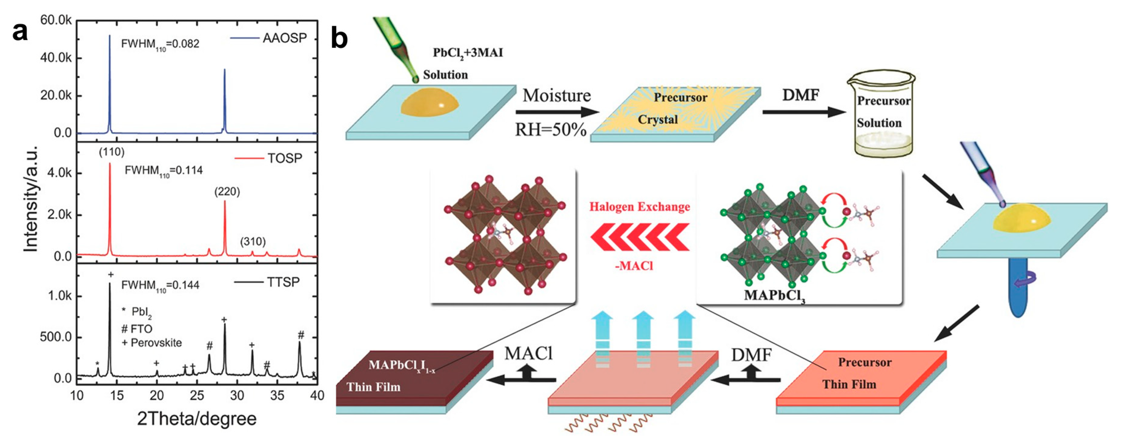
3.4.1. Solution Process Deposition
Spin Coating
- One-Step Spin Coating
- 2.
- Two-Step Spin Coating
Blade Coating and Slot-Die Coating
3.4.2. Evaporation Process Deposition
3.4.3. Solution and Evaporation Process Deposition
3.5. Annealing Process Engineering
3.6. Device Structure Engineering
4. Optimal Concentrations of Chlorine and Iodine
4.1. Efficiency
4.2. Stability
5. Challenges of Chloride–Iodide PSCs
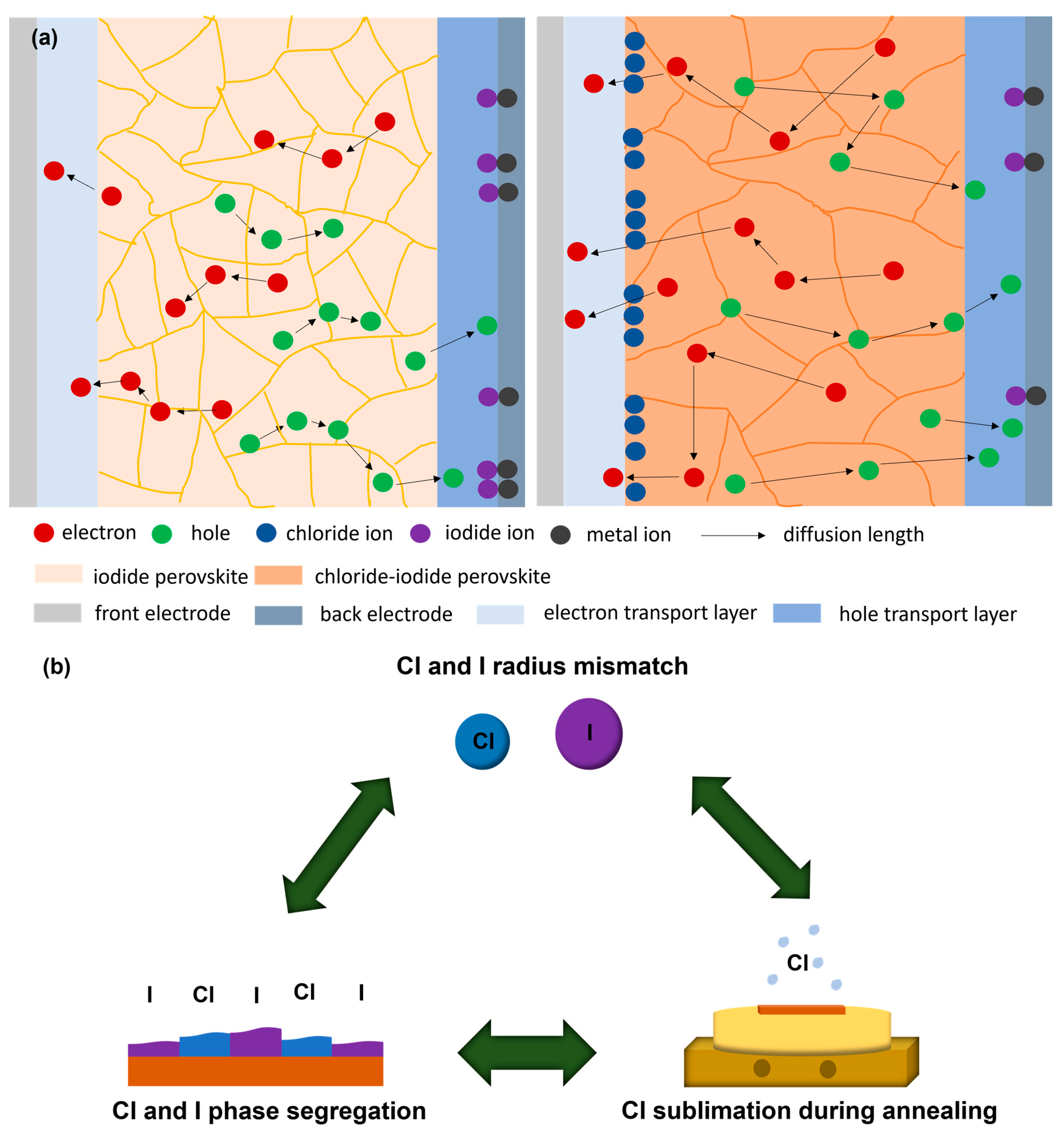
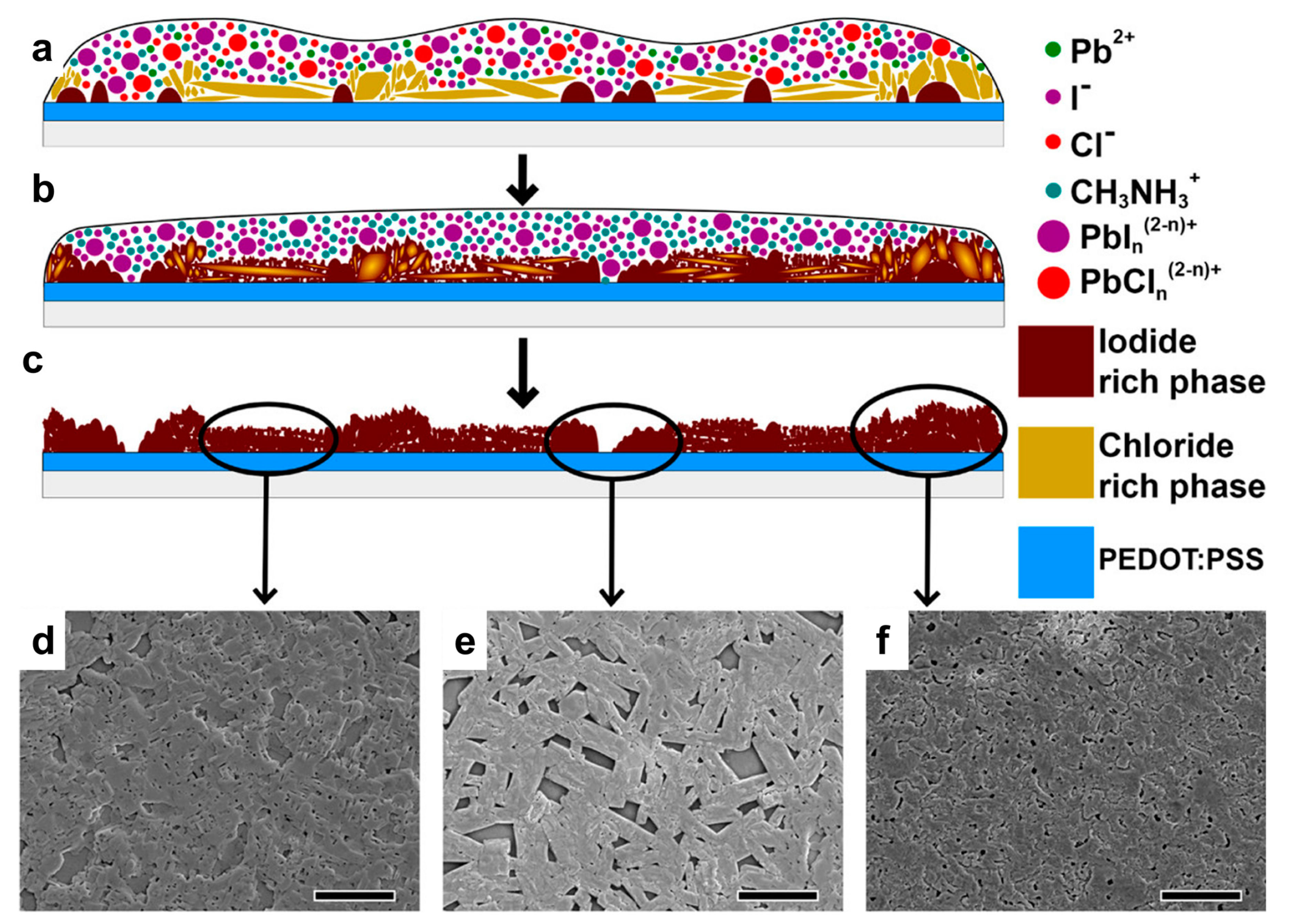
5.1. Chlorine and Iodine Phase Segregation
5.2. Chlorine and Iodine Radius Mismatch
5.3. Chlorine Sublimation during Annealing
5.4. Moisture Effect
5.5. Heat Effect
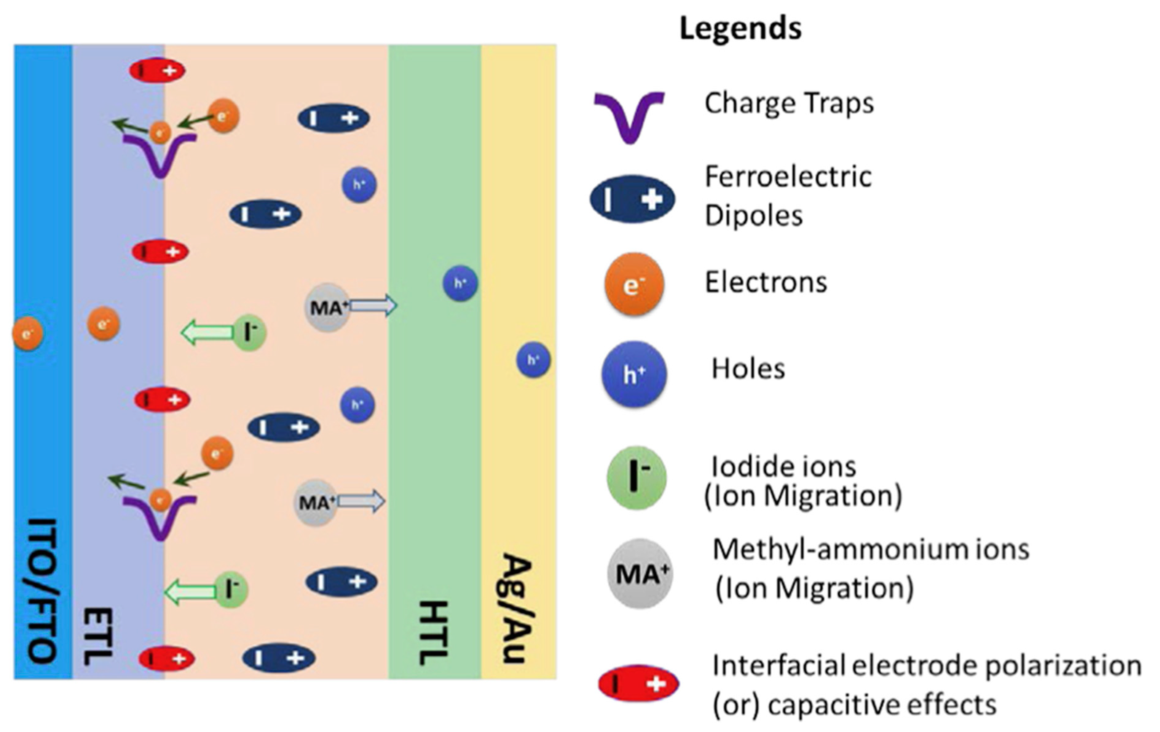
5.6. Light Effect
6. Conclusions
- Different molar ratios of precursors, such as MAI, MACl, PbI2, PbCl2, etc., are usually used to fabricate chloride–iodide perovskites. Excess MA+ ions produce unwanted MACl. MACl escapes from the film during annealing and creates Cl vacancies. In contrast, extra Cl contents result in a poorer PCE. It is found from Table 1 that a 5–10% Cl concentration is the optimal condition. However, in most of the literature, the Cl concentrations that are calculated for the precursor solution and measured in the film are not the same. Therefore, it is necessary to identify a more accurate molar ratio. Another way is to add 5–10% extra PbI2 to the chloride–iodide perovskite precursor solution. By adding PbI2, the recombination of electrons and holes should be reduced [157].
- Different Cl-containing additives can be used, especially those with bigger cation sizes than MA+ or FA+ cations. These additives would introduce only Cl− ions in the system. However, regarding the role of cations such as MA+ and FA+ in the additive, the cation needs to be large enough not to be incorporated into the lattice and thereby maintain the pristine perovskite bandgap. Additives such as ammonium chloride [158], poly ammonium chloride [159], etc., would be better candidates.
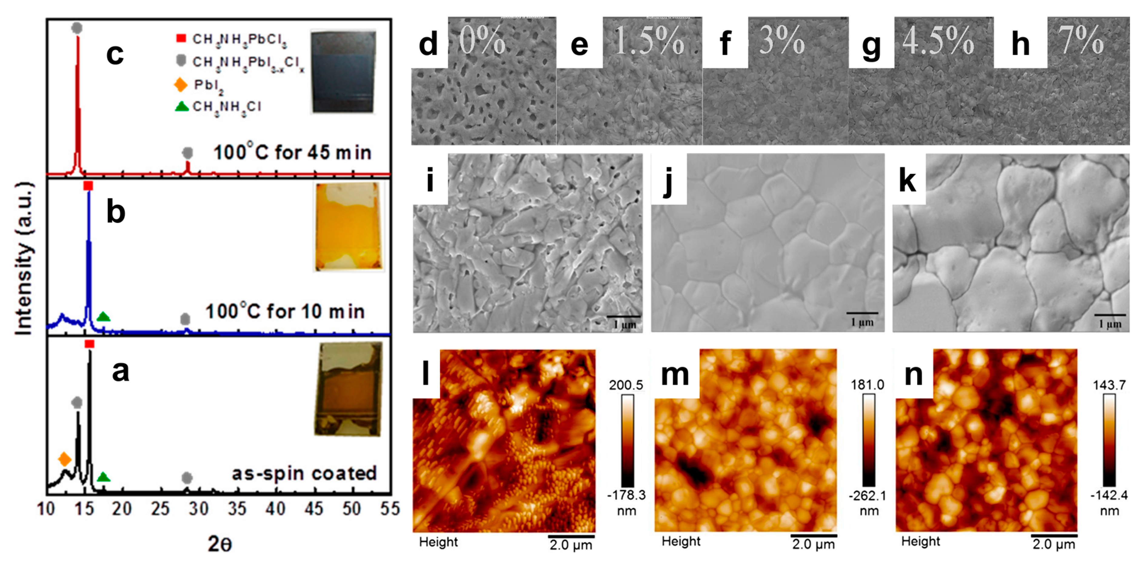
- Takeo et al. [160] found the best PCE with the chloride–iodide-based PSC fabricated at 140 °C. This is because in a temperature range of 130–150 °C, even in ambient air conditions, the humidity effect should be reduced. At the same time, this temperature would provide sufficient diffusion and interaction between the reactants for perovskite formation. In the case of chloride–iodide perovskite, annealing leads to the sublimation of Cl in the form of MACl. Specifically, annealing at more than 100 °C could initiate Cl sublimation. At the same time, at least 80 °C is necessary for perovskite crystallization. Therefore, to overcome this problem, annealing in the presence of moisture or solvents such as dimethylformamide can be performed to help reduce Cl sublimation.
- Dangling bonds on the perovskite film surface are responsible for the creation of surface states. These surface states work as trap states and increase nonradiative recombination. Thus, the Voc voltage is reduced, as well as the PCE. Again, grain boundaries in the polycrystalline thin film work as a permeation route for oxygen and moisture. Thus, they severely impact the stability of PSCs. Therefore, it is clear that the surface is a critical point for efficiency and stability. To solve these issues, interface engineering is a good option. It is possible to passivate positively and negatively charged defects by utilizing the Lewis acids and bases. In this regard, various functional groups, especially ligands (bidentate anilinium [161], ethylenediamine [162], etc.) are very effective passivators. As the halogen site of perovskite works as a Lewis base, any ligands that have Lewis acids will interact with each other. The electronegativity of chlorine is higher than that of iodine. Thus, the chlorine content in perovskite would facilitate more efficient interaction with Lewis acids. Another bottleneck of PSCs is the unprotected vertical side of the perovskite thin film. Moisture and water can easily penetrate through this lateral side. Post-device ligand treatment could effectively reduce this problem and increase the stability of PSCs. In post-device ligand treatment, ligand vapors will induce chemical modification in the selected lateral regions of the perovskite layer. This prevents the diffusion of moisture and oxygen into the protected active perovskite region, thus enhancing the PSC stability. For example, diethylenetriamine molecules can interact with MAPbI3 via the substitution of MA+ [163]. We know that in chloride–iodide perovskite, excess MA+ reacts with Cl− and forms MACl as a byproduct, which is not desirable. Through post-device ligand treatment, diethylenetriamine molecules reduce the quantity of MA+ and thus decrease the formation of MACl.
- HTL materials are crucial for the stability of the PSC. To date, Spiro-MeOTAD, P3HT, and PEDOT:PSS are usually used as HTL materials and can be deposited through cheap solution process deposition. Spiro-MeOTAD and P3HT are costly materials, although Spiro-MeOTAD is the most used HTL material. LiTFSI salt doping in Spiro-MeOTAD is needed to increase p-type conductivity. LiTFSI is a hydrophilic salt and is considered the main reason for the moisture-induced degradation of Spiro-MeOTAD. Again, in the case of chloride–iodide perovskite, there is a possibility of the formation of LiCl, which is hygroscopic and could affect the stability of the PSC. On the other hand, PEDOT:PSS is a comparatively cheap material, although it needs high annealing temperatures to remove water content. Thus, an annealing-free dry deposition process of PEDOT:PSS would be a good option. Oxidative chemical vapor deposition is an alternative option to deposit conductive polymers in dry conditions [164]. In this powerful method, polymerization, doping, and thin-film formation are possible to perform simultaneously. The mild fabrication conditions permit the direct deposition of polymer conducting layers onto thermally sensitive substrates.
- The biggest challenge for PSCs is to transfer them to the industry from the laboratory. To date, almost all efforts to improve their efficiency and stability have been on the laboratory scale and, of course, used cheap solution process methods. In laboratory-based small-size PSC fabrication with spin coating, researchers are struggling to make defectless interfacial contacts, as well as bulk films. Due to their small size, it is somewhat manageable to fabricate perovskite thin films with fewer defects, whereas, for large-size solution-based PSCs, slot-die coating is popular. For large-size solution-based PSC fabrication, controlling the defect density is very challenging. One possible way is to make thicker films, which will have a lower defect density. In this case, chloride–iodide perovskite offers an advantage for large-size commercial production. The carrier diffusion length is much longer for chloride–iodide perovskite compared to other types of perovskites. Again, another challenge is to control the surface roughness factor. A smoother surface has a lower roughness factor. For chloride–iodide perovskite preparation, there is a problem of the low solubility of PbI2 and PbCl2, even in DMF. In this case, two-step slot-die coating would be a possible solution. Chang et al. [165] prepared three types of solutions with PbI2—with only DMF, with both DMF and DMSO, and with only DMSO—in a two-step fabrication process to fabricate MAPbI3 films. They found a colloidal-like PbI2 solution with only DMSO and a much smoother surface with a lower surface roughness factor. Therefore, one possible way to overcome the problem is to make a PbCl2 colloidal solution in DMSO and deposit it on the MAI film in a two-step slot-die coating process.
Author Contributions
Funding
Data Availability Statement
Conflicts of Interest
References
- Elumalai, N.K.; Mahmud, M.A.; Wang, D.; Uddin, A. Perovskite Solar Cells: Progress and Advancements. Energies 2016, 9, 861. [Google Scholar] [CrossRef]
- Zhu, X. The Perovskite Fever and Beyond. Acc. Chem. Res. 2016, 49, 355–356. [Google Scholar] [CrossRef] [PubMed]
- Cheng, Y.; Ding, L. Pushing Commercialization of Perovskite Solar Cells by Improving Their Intrinsic Stability. Energy Environ. Sci. 2021, 14, 3233–3255. [Google Scholar] [CrossRef]
- Huang, J.; Shao, Y.; Dong, Q. Organometal Trihalide Perovskite Single Crystals: A Next Wave of Materials for 25% Efficiency Photovoltaics and Applications Beyond? J. Phys. Chem. Lett. 2015, 6, 3218–3227. [Google Scholar] [CrossRef]
- Babayigit, A.; Ethirajan, A.; Muller, M.; Conings, B. Toxicity of Organometal Halide Perovskite Solar Cells. Nat. Mater. 2016, 15, 247–251. [Google Scholar] [CrossRef] [PubMed]
- Noel, N.K.; Stranks, S.D.; Abate, A.; Wehrenfennig, C.; Guarnera, S.; Haghighirad, A.-A.; Sadhanala, A.; Eperon, G.E.; Pathak, S.K.; Johnston, M.B.; et al. Lead-Free Organic–Inorganic Tin Halide Perovskites for Photovoltaic Applications. Energy Environ. Sci. 2014, 7, 3061–3068. [Google Scholar] [CrossRef]
- Hao, F.; Stoumpos, C.C.; Cao, D.H.; Chang, R.P.H.; Kanatzidis, M.G. Lead-Free Solid-State Organic–Inorganic Halide Perovskite Solar Cells. Nat. Photonics 2014, 8, 489–494. [Google Scholar] [CrossRef]
- Abdelhady, A.L.; Saidaminov, M.I.; Murali, B.; Adinolfi, V.; Voznyy, O.; Katsiev, K.; Alarousu, E.; Comin, R.; Dursun, I.; Sinatra, L.; et al. Heterovalent Dopant Incorporation for Bandgap and Type Engineering of Perovskite Crystals. J. Phys. Chem. Lett. 2016, 7, 295–301. [Google Scholar] [CrossRef]
- Navas, J.; Sánchez-Coronilla, A.; Jesús Gallardo, J.; Hernández, N.C.; Carlos Piñero, J.; Alcántara, R.; Fernández-Lorenzo, C.; Los Santos, D.M.D.; Aguilar, T.; Martín-Calleja, J. New Insights into Organic–Inorganic Hybrid Perovskite CH3NH3PbI3 Nanoparticles. An Experimental and Theoretical Study of Doping in Pb2+ Sites with Sn2+, Sr2+, Cd2+ and Ca2+. Nanoscale 2015, 7, 6216–6229. [Google Scholar] [CrossRef]
- Xu, F.; Zhang, M.; Li, Z.; Yang, X.; Zhu, R. Challenges and Perspectives toward Future Wide-Bandgap Mixed-Halide Perovskite Photovoltaics. Adv. Energy Mater. 2023, 13, 2203911. [Google Scholar] [CrossRef]
- Zhang, F.; Yang, B.; Li, Y.; Deng, W.; He, R. Extra Long Electron–Hole Diffusion Lengths in CH3NH3PbI3−xClx Perovskite Single Crystals. J. Mater. Chem. C 2017, 5, 8431–8435. [Google Scholar] [CrossRef]
- Stranks, S.D.; Eperon, G.E.; Grancini, G.; Menelaou, C.; Alcocer, M.J.P.; Leijtens, T.; Herz, L.M.; Petrozza, A.; Snaith, H.J. Electron-Hole Diffusion Lengths Exceeding 1 Micrometer in an Organometal Trihalide Perovskite Absorber. Science 2013, 342, 341–344. [Google Scholar] [CrossRef]
- Huang, C.; Fu, N.; Liu, F.; Jiang, L.; Hao, X.; Huang, H. Highly Efficient Perovskite Solar Cells with Precursor Composition-Dependent Morphology. Sol. Energy Mater. Sol. Cells 2016, 145, 231–237. [Google Scholar] [CrossRef]
- Yang, L.; Barrows, A.T.; Lidzey, D.G.; Wang, T. Recent Progress and Challenges of Organometal Halide Perovskite Solar Cells. Rep. Prog. Phys. 2016, 79, 026501. [Google Scholar] [CrossRef]
- Lee, M.M.; Teuscher, J.; Miyasaka, T.; Murakami, T.N.; Snaith, H.J. Efficient Hybrid Solar Cells Based on Meso-Superstructured Organometal Halide Perovskites. Science 2012, 338, 643–647. [Google Scholar] [CrossRef] [PubMed]
- Conings, B.; Baeten, L.; De Dobbelaere, C.; D’Haen, J.; Manca, J.; Boyen, H.-G. Perovskite-Based Hybrid Solar Cells Exceeding 10% Efficiency with High Reproducibility Using a Thin Film Sandwich Approach. Adv. Mater. 2014, 26, 2041–2046. [Google Scholar] [CrossRef]
- Ball, J.M.; Lee, M.M.; Hey, A.; Snaith, H.J. Low-Temperature Processed Meso-Superstructured to Thin-Film Perovskite Solar Cells. Energy Environ. Sci. 2013, 6, 1739–1743. [Google Scholar] [CrossRef]
- Eperon, G.E.; Burlakov, V.M.; Docampo, P.; Goriely, A.; Snaith, H.J. Morphological Control for High Performance, Solution-Processed Planar Heterojunction Perovskite Solar Cells. Adv. Funct. Mater. 2014, 24, 151–157. [Google Scholar] [CrossRef]
- You, J.; Hong, Z.; Yang, Y.; Chen, Q.; Cai, M.; Song, T.-B.; Chen, C.-C.; Lu, S.; Liu, Y.; Zhou, H.; et al. Low-Temperature Solution-Processed Perovskite Solar Cells with High Efficiency and Flexibility. ACS Nano 2014, 8, 1674–1680. [Google Scholar] [CrossRef]
- Wang, D.; Liu, Z.; Zhou, Z.; Zhu, H.; Zhou, Y.; Huang, C.; Wang, Z.; Xu, H.; Jin, Y.; Fan, B.; et al. Reproducible One-Step Fabrication of Compact MAPbI3–XClx Thin Films Derived from Mixed-Lead-Halide Precursors. Chem. Mater. 2014, 26, 7145–7150. [Google Scholar] [CrossRef]
- Jiang, M.; Wu, J.; Lan, F.; Tao, Q.; Gao, D.; Li, G. Enhancing the Performance of Planar Organo-Lead Halide Perovskite Solar Cells by Using a Mixed Halide Source. J. Mater. Chem. A 2014, 3, 963–967. [Google Scholar] [CrossRef]
- Dharani, S.; Dewi, H.A.; Prabhakar, R.R.; Baikie, T.; Shi, C.; Yonghua, D.; Mathews, N.; Boix, P.P.; Mhaisalkar, S.G. Incorporation of Cl into Sequentially Deposited Lead Halide Perovskite Films for Highly Efficient Mesoporous Solar Cells. Nanoscale 2014, 6, 13854–13860. [Google Scholar] [CrossRef]
- Docampo, P.; Hanusch, F.C.; Stranks, S.D.; Döblinger, M.; Feckl, J.M.; Ehrensperger, M.; Minar, N.K.; Johnston, M.B.; Snaith, H.J.; Bein, T. Solution Deposition-Conversion for Planar Heterojunction Mixed Halide Perovskite Solar Cells. Adv. Energy Mater. 2014, 4, 1400355. [Google Scholar] [CrossRef]
- Dong, Q.; Yuan, Y.; Shao, Y.; Fang, Y.; Wang, Q.; Huang, J. Abnormal Crystal Growth in CH3NH3PbI3−xClx Using a Multi-Cycle Solution Coating Process. Energy Environ. Sci. 2015, 8, 2464–2470. [Google Scholar] [CrossRef]
- Chen, Y.; Chen, T.; Dai, L. Layer-by-Layer Growth of CH3NH3PbI3−xClx for Highly Efficient Planar Heterojunction Perovskite Solar Cells. Adv. Mater. 2015, 27, 1053–1059. [Google Scholar] [CrossRef]
- Liu, M.; Johnston, M.B.; Snaith, H.J. Efficient Planar Heterojunction Perovskite Solar Cells by Vapour Deposition. Nature 2013, 501, 395–398. [Google Scholar] [CrossRef]
- Luo, P.; Liu, Z.; Xia, W.; Yuan, C.; Cheng, J.; Xu, C.; Lu, Y. Chlorine-Conducted Defect Repairment and Seed Crystal-Mediated Vapor Growth Process for Controllable Preparation of Efficient and Stable Perovskite Solar Cells. J. Mater. Chem. A 2015, 3, 22949–22959. [Google Scholar] [CrossRef]
- Liu, D.; Wu, L.; Li, C.; Ren, S.; Zhang, J.; Li, W.; Feng, L. Controlling CH3NH3PbI3–XClx Film Morphology with Two-Step Annealing Method for Efficient Hybrid Perovskite Solar Cells. ACS Appl. Mater. Interfaces 2015, 7, 16330–16337. [Google Scholar] [CrossRef] [PubMed]
- Chen, Q.; Zhou, H.; Fang, Y.; Stieg, A.Z.; Song, T.-B.; Wang, H.-H.; Xu, X.; Liu, Y.; Lu, S.; You, J.; et al. The Optoelectronic Role of Chlorine in CH3NH3PbI3(Cl)-Based Perovskite Solar Cells. Nat. Commun. 2015, 6, 7269. [Google Scholar] [CrossRef]
- Li, W.; Fan, J.; Mai, Y.; Wang, L. Aquointermediate Assisted Highly Orientated Perovskite Thin Films toward Thermally Stable and Efficient Solar Cells. Adv. Energy Mater. 2017, 7, 1601433. [Google Scholar] [CrossRef]
- Ahmadi, M.; Hsiao, Y.-C.; Wu, T.; Liu, Q.; Qin, W.; Hu, B. Effect of Photogenerated Dipoles in the Hole Transport Layer on Photovoltaic Performance of Organic–Inorganic Perovskite Solar Cells. Adv. Energy Mater. 2017, 7, 1601575. [Google Scholar] [CrossRef]
- Liao, H.-C.; Guo, P.; Hsu, C.-P.; Lin, M.; Wang, B.; Zeng, L.; Huang, W.; Soe, C.M.M.; Su, W.-F.; Bedzyk, M.J.; et al. Enhanced Efficiency of Hot-Cast Large-Area Planar Perovskite Solar Cells/Modules Having Controlled Chloride Incorporation. Adv. Energy Mater. 2017, 7, 1601660. [Google Scholar] [CrossRef]
- Mu, C.; Pan, J.; Feng, S.; Li, Q.; Xu, D. Quantitative Doping of Chlorine in Formamidinium Lead Trihalide (FAPbI3−xClx) for Planar Heterojunction Perovskite Solar Cells. Adv. Energy Mater. 2017, 7, 1601297. [Google Scholar] [CrossRef]
- Qing, J.; Chandran, H.-T.; Cheng, Y.-H.; Liu, X.-K.; Li, H.-W.; Tsang, S.-W.; Lo, M.-F.; Lee, C.-S. Chlorine Incorporation for Enhanced Performance of Planar Perovskite Solar Cell Based on Lead Acetate Precursor. ACS Appl. Mater. Interfaces 2015, 7, 23110–23116. [Google Scholar] [CrossRef] [PubMed]
- Liu, J.; Lin, J.; Xue, Q.; Ye, Q.; He, X.; Ouyang, L.; Zhuang, D.; Liao, C.; Yip, H.-L.; Mei, J.; et al. Growth and Evolution of Solution-Processed CH3NH3PbI3-XClx Layer for Highly Efficient Planar-Heterojunction Perovskite Solar Cells. J. Power Sources 2016, 301, 242–250. [Google Scholar] [CrossRef]
- Rao, H.; Ye, S.; Sun, W.; Yan, W.; Li, Y.; Peng, H.; Liu, Z.; Bian, Z.; Li, Y.; Huang, C. A 19.0% Efficiency Achieved in CuOx-Based Inverted CH3NH3PbI3−xClx Solar Cells by an Effective Cl Doping Method. Nano Energy 2016, 27, 51–57. [Google Scholar] [CrossRef]
- Islam, B.; Yanagida, M.; Shirai, Y.; Nabetani, Y.; Miyano, K. NiOx Hole Transport Layer for Perovskite Solar Cells with Improved Stability and Reproducibility. ACS Omega 2017, 2, 2291–2299. [Google Scholar] [CrossRef] [PubMed]
- Hu, L.; Li, M.; Yang, K.; Xiong, Z.; Yang, B.; Wang, M.; Tang, X.; Zang, Z.; Liu, X.; Li, B.; et al. PEDOT:PSS Monolayers to Enhance the Hole Extraction and Stability of Perovskite Solar Cells. J. Mater. Chem. A 2018, 6, 16583–16589. [Google Scholar] [CrossRef]
- Peng, L.; Liu, Z. Reduce the Hysteresis Effect with the PEIE Interface Dipole Effect in the Organic-Inorganic Hybrid Perovskite CH3NH3PbI3-XClx Solar Cell. Org. Electron. 2018, 62, 630–636. [Google Scholar] [CrossRef]
- Zeng, X.; Zhou, T.; Leng, C.; Zang, Z.; Wang, M.; Hu, W.; Tang, X.; Lu, S.; Fang, L.; Zhou, M. Performance Improvement of Perovskite Solar Cells by Employing a CdSe Quantum Dot/PCBM Composite as an Electron Transport Layer. J. Mater. Chem. A 2017, 5, 17499–17505. [Google Scholar] [CrossRef]
- Peng, L.; Xie, W.; Yang, C. Study of the Effect of DIO Additive on Charge Extraction and Recombination in Organic–Inorganic Hybrid MAPbI3−xClx Perovskite Solar Cell. RSC Adv. 2018, 70, 40298–40307. [Google Scholar] [CrossRef]
- Yu, H.; Zhang, Q.; Han, C.; Zhu, X.; Sun, X.; Yang, Q.; Yang, H.; Deng, L.; Zhao, F.; Wang, K.; et al. Improving Photovoltaic Performance of Inverted Planar Structure Perovskite Solar Cells via Introducing Photogenerated Dipoles in the Electron Transport Layer. Org. Electron. 2018, 63, 137–142. [Google Scholar] [CrossRef]
- Han, C.; Yu, H.; Duan, J.; Lu, K.; Zhang, J.; Shao, M.; Hu, B. Introducing Optically Polarizable Molecules into Perovskite Solar Cells by Simultaneously Enhanced Spin–Orbital Coupling, Suppressed Non-Radiative Recombination and Improved Transport Balance towards Enhancing Photovoltaic Actions. J. Mater. Chem. C 2018, 6, 6164–6171. [Google Scholar] [CrossRef]
- Mamun, A.A.; Ava, T.T.; Jeong, H.J.; Jeong, M.S.; Namkoong, G. A Deconvoluted PL Approach to Probe the Charge Carrier Dynamics of the Grain Interior and Grain Boundary of a Perovskite Film for Perovskite Solar Cell Applications. Phys. Chem. Chem. Phys. 2017, 19, 9143–9148. [Google Scholar] [CrossRef] [PubMed]
- Ko, Y.; Choi, W.Y.; Yun, Y.J.; Jun, Y. A PbI2−xClx Seed Layer for Obtaining Efficient Planar-Heterojunction Perovskite Solar Cells via an Interdiffusion Process. Nanoscale 2017, 9, 9396–9403. [Google Scholar] [CrossRef] [PubMed]
- Park, B.; Zhang, X.; Johansson, E.M.J.; Hagfeldt, A.; Boschloo, G.; Seok, S.I.; Edvinsson, T. Analysis of Crystalline Phases and Integration Modelling of Charge Quenching Yields in Hybrid Lead Halide Perovskite Solar Cell Materials. Nano Energy 2017, 40, 596–606. [Google Scholar] [CrossRef]
- Wang, S.; Guan, H.; Yin, Y.; Zhang, C. The Performance Improvement of Using Hole Transport Layer with Lithium and Cobalt for Inverted Planar Perovskite Solar Cell. Coatings 2020, 10, 354. [Google Scholar] [CrossRef]
- Liu, Y.; Shin, I.; Hwang, I.-W.; Lee, J.; Kim, S.; Lee, D.Y.; Lee, S.-H.; Jang, J.-W.; Jung, Y.K.; Jeong, J.H.; et al. Effective Hot-Air Annealing for Improving the Performance of Perovskite Solar Cells. Sol. Energy 2017, 146, 359–367. [Google Scholar] [CrossRef]
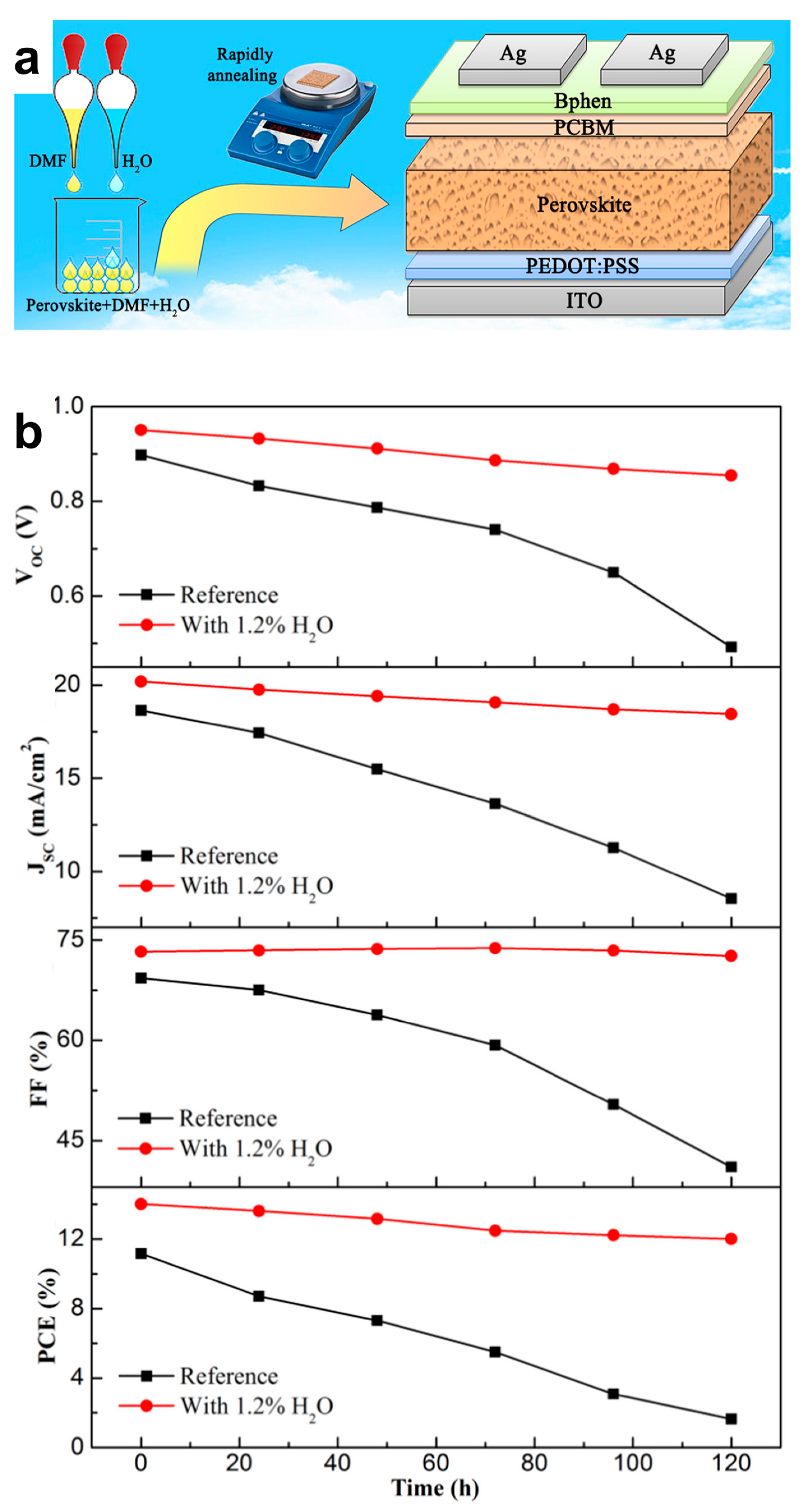
- He, T.; Liu, Z.; Zhou, Y.; Ma, H. The Stable Perovskite Solar Cell Prepared by Rapidly Annealing Perovskite Film with Water Additive in Ambient Air. Sol. Energy Mater. Sol. Cells 2018, 176, 280–287. [Google Scholar] [CrossRef]
- Zhang, Z.L.; Men, B.Q.; Liu, Y.F.; Gao, H.P.; Mao, Y.L. Effects of Precursor Solution Composition on the Performance and I-V Hysteresis of Perovskite Solar Cells Based on CH3NH3PbI3−xClx. Nanoscale Res. Lett. 2017, 12, 84. [Google Scholar] [CrossRef]
- Fan, L.; Ding, Y.; Luo, J.; Shi, B.; Yao, X.; Wei, C.; Zhang, D.; Wang, G.; Sheng, Y.; Chen, Y.; et al. Elucidating the Role of Chlorine in Perovskite Solar Cells. J. Mater. Chem. A 2017, 5, 7423–7432. [Google Scholar] [CrossRef]
- Duy Pham, N.; Tiing Tiong, V.; Chen, P.; Wang, L.; Wilson, G.J.; Bell, J.; Wang, H. Enhanced Perovskite Electronic Properties via a Modified Lead(Ii) Chloride Lewis Acid–Base Adduct and Their Effect in High-Efficiency Perovskite Solar Cells. J. Mater. Chem. A 2017, 5, 5195–5203. [Google Scholar] [CrossRef]
- Cao, X.; Zhi, L.; Jia, Y.; Li, Y.; Zhao, K.; Cui, X.; Ci, L.; Ding, K.; Wei, J. Enhanced Efficiency of Perovskite Solar Cells by Introducing Controlled Chloride Incorporation into MAPbI3 Perovskite Films. Electrochim. Acta 2018, 275, 1–7. [Google Scholar] [CrossRef]
- Li, S.; He, B.; Xu, J.; Lu, H.; Jiang, J.; Zhu, J.; Kan, Z.; Zhu, L.; Wu, F. Highly Efficient Inverted Perovskite Solar Cells Incorporating P3CT-Rb as a Hole Transport Layer to Achieve a Large Open Circuit Voltage of 1.144 V. Nanoscale 2020, 12, 3686–3691. [Google Scholar] [CrossRef]
- Jang, J.; Choe, G.; Yim, S. Effective Control of Chlorine Contents in MAPbI3−xClx Perovskite Solar Cells Using a Single-Source Vapor Deposition and Anion-Exchange Technique. ACS Appl. Mater. Interfaces 2019, 11, 20073–20081. [Google Scholar] [CrossRef]
- Wu, Y.; Li, X.; Fu, S.; Wan, L.; Fang, J. Efficient Methylammonium Lead Trihalide Perovskite Solar Cells with Chloroformamidinium Chloride (Cl-FACl) as an Additive. J. Mater. Chem. A 2019, 7, 8078–8084. [Google Scholar] [CrossRef]
- Huang, L.; Cui, X.; Liu, C.; Yang, W.; Shi, W.; Lai, J.; Wang, L. Improvement on Performance of Hybrid CH3NH3PbI3−xClx Perovskite Solar Cells Induced Sequential Deposition by Low Pressure Assisted Solution Processing. Sol. Energy 2020, 199, 826–831. [Google Scholar] [CrossRef]
- Ngqoloda, S.; Arendse, C.J.; Guha, S.; Muller, T.F.; Klue, S.C.; Magubane, S.S.; Oliphant, C.J. Mixed-Halide Perovskites Solar Cells through PbICl and PbCl2 Precursor Films by Sequential Chemical Vapor Deposition. Sol. Energy 2021, 215, 179–188. [Google Scholar] [CrossRef]
- Siva, U.; Murugathas, T.; Yohi, S.; Natarajan, M.; Velauthapillai, D.; Ravirajan, P. Single Walled Carbon Nanotube Incorporated Titanium Dioxide and Poly(3-Hexylthiophene) as Electron and Hole Transport Materials for Perovskite Solar Cells. Mater. Lett. 2020, 276, 128174. [Google Scholar] [CrossRef]
- Heo, J.H.; Im, S.H. Highly Reproducible, Efficient Hysteresis-Less CH3NH3PbI3−xClx Planar Hybrid Solar Cells without Requiring Heat-Treatment. Nanoscale 2016, 8, 2554–2560. [Google Scholar] [CrossRef]
- Giuliano, G.; Bonasera, A.; Scopelliti, M.; Chillura Martino, D.; Fiore, T.; Pignataro, B. Boosting the Performance of One-Step Solution-Processed Perovskite Solar Cells Using a Natural Monoterpene Alcohol as a Green Solvent Additive. ACS Appl. Electron. Mater. 2021, 3, 1813–1825. [Google Scholar] [CrossRef]
- Wang, Y.; Chen, Q.; Fu, J.; Liu, Z.; Sun, Z.; Zhang, S.; Zhu, Y.; Jia, X.; Zhang, J.; Yuan, N.; et al. Annealing- and Doping-Free Hole Transport Material for p-i-n Perovskite Solar Cells with Efficiency Achieving over 21%. Chem. Eng. J. 2022, 433, 133265. [Google Scholar] [CrossRef]
- Zhao, Y.; Zhu, K. CH3NH3Cl-Assisted One-Step Solution Growth of CH3NH3PbI3: Structure, Charge-Carrier Dynamics, and Photovoltaic Properties of Perovskite Solar Cells. J. Phys. Chem. C 2014, 118, 9412–9418. [Google Scholar] [CrossRef]
- Pool, V.L.; Gold-Parker, A.; McGehee, M.D.; Toney, M.F. Chlorine in PbCl2-Derived Hybrid-Perovskite Solar Absorbers. Chem. Mater. 2015, 27, 7240–7243. [Google Scholar] [CrossRef]
- Tidhar, Y.; Edri, E.; Weissman, H.; Zohar, D.; Hodes, G.; Cahen, D.; Rybtchinski, B.; Kirmayer, S. Crystallization of Methyl Ammonium Lead Halide Perovskites: Implications for Photovoltaic Applications. J. Am. Chem. Soc. 2014, 136, 13249–13256. [Google Scholar] [CrossRef]
- Colella, S.; Mosconi, E.; Pellegrino, G.; Alberti, A.; Guerra, V.L.P.; Masi, S.; Listorti, A.; Rizzo, A.; Condorelli, G.G.; De Angelis, F.; et al. Elusive Presence of Chloride in Mixed Halide Perovskite Solar Cells. J. Phys. Chem. Lett. 2014, 5, 3532–3538. [Google Scholar] [CrossRef] [PubMed]
- Unger, E.L.; Bowring, A.R.; Tassone, C.J.; Pool, V.L.; Gold-Parker, A.; Cheacharoen, R.; Stone, K.H.; Hoke, E.T.; Toney, M.F.; McGehee, M.D. Chloride in Lead Chloride-Derived Organo-Metal Halides for Perovskite-Absorber Solar Cells. Chem. Mater. 2014, 26, 7158–7165. [Google Scholar] [CrossRef]
- Salim, T.; Sun, S.; Abe, Y.; Krishna, A.; Grimsdale, A.C.; Lam, Y.M. Perovskite-Based Solar Cells: Impact of Morphology and Device Architecture on Device Performance. J. Mater. Chem. A 2015, 3, 8943–8969. [Google Scholar] [CrossRef]
- Qiao, W.-C.; Yang, J.; Dong, W.; Yang, G.; Bao, Q.; Huang, R.; Wang, X.L.; Yao, Y.-F. Metastable Alloying Structures in MAPbI3−xClx Crystals. NPG Asia Mater. 2020, 12, 68. [Google Scholar] [CrossRef]
- Bartel, C.J.; Sutton, C.; Goldsmith, B.R.; Ouyang, R.; Musgrave, C.B.; Ghiringhelli, L.M.; Scheffler, M. New Tolerance Factor to Predict the Stability of Perovskite Oxides and Halides. Sci. Adv. 2019, 5, eaav0693. [Google Scholar] [CrossRef] [PubMed]
- McLeod, J.A.; Wu, Z.; Sun, B.; Liu, L. The Influence of the I/Cl Ratio on the Performance of CH3NH3PbI3−xClx-Based Solar Cells: Why Is CH3NH3I:PbCl2=3:1 the “Magic” Ratio? Nanoscale 2016, 8, 6361–6368. [Google Scholar] [CrossRef]
- Xu, F.; Zhang, T.; Li, G.; Zhao, Y. Synergetic Effect of Chloride Doping and CH3NH3PbCl3 on CH3NH3PbI3−xClx Perovskite-Based Solar Cells. ChemSusChem 2017, 10, 2365–2369. [Google Scholar] [CrossRef] [PubMed]
- Bouchard, M.; Hilhorst, J.; Pouget, S.; Alam, F.; Mendez, M.; Djurado, D.; Aldakov, D.; Schülli, T.; Reiss, P. Direct Evidence of Chlorine-Induced Preferential Crystalline Orientation in Methylammonium Lead Iodide Perovskites Grown on TiO2. J. Phys. Chem. C 2017, 121, 7596–7602. [Google Scholar] [CrossRef]
- Kim, H.-S.; Hagfeldt, A.; Park, N.-G. Morphological and Compositional Progress in Halide Perovskite Solar Cells. Chem. Commun. 2019, 55, 1192–1200. [Google Scholar] [CrossRef] [PubMed]
- Williams, S.T.; Zuo, F.; Chueh, C.-C.; Liao, C.-Y.; Liang, P.-W.; Jen, A.K.-Y. Role of Chloride in the Morphological Evolution of Organo-Lead Halide Perovskite Thin Films. ACS Nano 2014, 8, 10640–10654. [Google Scholar] [CrossRef] [PubMed]
- Dar, M.I.; Arora, N.; Gao, P.; Ahmad, S.; Grätzel, M.; Nazeeruddin, M.K. Investigation Regarding the Role of Chloride in Organic–Inorganic Halide Perovskites Obtained from Chloride Containing Precursors. Nano Lett. 2014, 14, 6991–6996. [Google Scholar] [CrossRef]
- Colella, S.; Mosconi, E.; Fedeli, P.; Listorti, A.; Gazza, F.; Orlandi, F.; Ferro, P.; Besagni, T.; Rizzo, A.; Calestani, G.; et al. MAPbI3−xClx Mixed Halide Perovskite for Hybrid Solar Cells: The Role of Chloride as Dopant on the Transport and Structural Properties. Chem. Mater. 2013, 25, 4613–4618. [Google Scholar] [CrossRef]
- Yantara, N.; Yanan, F.; Shi, C.; Dewi, H.A.; Boix, P.P.; Mhaisalkar, S.G.; Mathews, N. Unravelling the Effects of Cl Addition in Single Step CH3NH3PbI3 Perovskite Solar Cells. Chem. Mater. 2015, 27, 2309–2314. [Google Scholar] [CrossRef]
- Tombe, S.; Adam, G.; Heilbrunner, H.; Yumusak, C.; Apaydin, D.H.; Hailegnaw, B.; Ulbricht, C.; Arendse, C.J.; Langhals, H.; Iwuohaa, E.; et al. The Influence of Perovskite Precursor Composition on the Morphology and Photovoltaic Performance of Mixed Halide MAPbI3-XClx Solar Cells. Sol. Energy 2018, 163, 215–223. [Google Scholar] [CrossRef]
- Li, T.; Pan, Y.; Wang, Z.; Xia, Y.; Chen, Y.; Huang, W. Additive Engineering for Highly Efficient Organic–Inorganic Halide Perovskite Solar Cells: Recent Advances and Perspectives. J. Mater. Chem. A 2017, 5, 12602–12652. [Google Scholar] [CrossRef]
- Zhang, F.; Zhu, K. Additive Engineering for Efficient and Stable Perovskite Solar Cells. Adv. Energy Mater. 2020, 10, 1902579. [Google Scholar] [CrossRef]
- Pereyra, C.; Xie, H.; Lira-Cantu, M. Additive Engineering for Stable Halide Perovskite Solar Cells. J. Energy Chem. 2021, 60, 599–634. [Google Scholar] [CrossRef]
- Mahapatra, A.; Prochowicz, D.; Tavakoli, M.M.; Trivedi, S.; Kumar, P.; Yadav, P.K. A Review of Aspects of Additive Engineering in Perovskite Solar Cells. J. Mater. Chem. A 2020, 8, 27–54. [Google Scholar] [CrossRef]
- Wang, L.; Liu, G.; Xi, X.; Yang, G.; Hu, L.; Zhu, B.; He, Y.; Liu, Y.; Qian, H.; Zhang, S.; et al. Annealing Engineering in the Growth of Perovskite Grains. Crystals 2022, 12, 894. [Google Scholar] [CrossRef]
- Dong, H.; Pang, S.; He, F.; Yang, H.; Zhu, W.; Chen, D.; Xi, H.; Zhang, J.; Hao, Y.; Zhang, C. Annealing-Free, High-Performance Perovskite Solar Cells by Controlling Crystallization via Guanidinium Cation Doping. Sol. RRL 2021, 5, 2100097. [Google Scholar] [CrossRef]
- Dubey, A.; Adhikari, N.; Mabrouk, S.; Wu, F.; Chen, K.; Yang, S.; Qiao, Q. A Strategic Review on Processing Routes towards Highly Efficient Perovskite Solar Cells. J. Mater. Chem. A 2018, 6, 2406–2431. [Google Scholar] [CrossRef]
- Cao, X.; Zhi, L.; Jia, Y.; Li, Y.; Zhao, K.; Cui, X.; Ci, L.; Zhuang, D.; Wei, J. A Review of the Role of Solvents in Formation of High-Quality Solution-Processed Perovskite Films. ACS Appl. Mater. Interfaces 2019, 11, 7639–7654. [Google Scholar] [CrossRef] [PubMed]
- Chao, L.; Niu, T.; Gao, W.; Ran, C.; Song, L.; Chen, Y.; Huang, W. Solvent Engineering of the Precursor Solution toward Large-Area Production of Perovskite Solar Cells. Adv. Mater. 2021, 33, 2005410. [Google Scholar] [CrossRef]
- Mehdi, H.; Mhamdi, A.; Bouazizi, A. Effect of Perovskite Precursor Ratios and Solvents Volume on the Efficiency of MAPbI3-XClx Mixed Halide Perovskite Solar Cells. Mater. Sci. Semicond. Process. 2020, 109, 104915. [Google Scholar] [CrossRef]
- Buin, A.; Comin, R.; Xu, J.; Ip, A.H.; Sargent, E.H. Halide-Dependent Electronic Structure of Organolead Perovskite Materials. Chem. Mater. 2015, 27, 4405–4412. [Google Scholar] [CrossRef]
- Tong, G.; Son, D.-Y.; Ono, L.K.; Liu, Y.; Hu, Y.; Zhang, H.; Jamshaid, A.; Qiu, L.; Liu, Z.; Qi, Y. Scalable Fabrication of >90 cm2 Perovskite Solar Modules with >1000 h Operational Stability Based on the Intermediate Phase Strategy. Adv. Energy Mater. 2021, 11, 2003712. [Google Scholar] [CrossRef]
- Niu, G.; Guo, X.; Wang, L. Review of Recent Progress in Chemical Stability of Perovskite Solar Cells. J. Mater. Chem. A 2015, 3, 8970–8980. [Google Scholar] [CrossRef]
- Liu, Y.; Feng, K.; Hsieh, R.-H.; Mo, X. CH3NH3PbIxCl(3−x) Thin Film Prepared by Vapor Transfer Method for Perovskite Solar Cells. Mater. Lett. 2019, 239, 163–166. [Google Scholar] [CrossRef]
- Grätzel, M. The Light and Shade of Perovskite Solar Cells. Nat. Mater. 2014, 13, 838–842. [Google Scholar] [CrossRef] [PubMed]
- Dualeh, A.; Tétreault, N.; Moehl, T.; Gao, P.; Nazeeruddin, M.K.; Grätzel, M. Effect of Annealing Temperature on Film Morphology of Organic–Inorganic Hybrid Pervoskite Solid-State Solar Cells. Adv. Funct. Mater. 2014, 24, 3250–3258. [Google Scholar] [CrossRef]
- Tan, K.W.; Moore, D.T.; Saliba, M.; Sai, H.; Estroff, L.A.; Hanrath, T.; Snaith, H.J.; Wiesner, U. Thermally Induced Structural Evolution and Performance of Mesoporous Block Copolymer-Directed Alumina Perovskite Solar Cells. ACS Nano 2014, 8, 4730–4739. [Google Scholar] [CrossRef]
- Yu, H.; Wang, F.; Xie, F.; Li, W.; Chen, J.; Zhao, N. The Role of Chlorine in the Formation Process of “CH3NH3PbI3-XClx” Perovskite. Adv. Funct. Mater. 2014, 24, 7102–7108. [Google Scholar] [CrossRef]
- Ralaiarisoa, M.; Busby, Y.; Frisch, J.; Salzmann, I.; Pireaux, J.-J.; Koch, N. Correlation of Annealing Time with Crystal Structure, Composition, and Electronic Properties of CH3NH3PbI3−xClx Mixed-Halide Perovskite Films. Phys. Chem. Chem. Phys. 2016, 19, 828–836. [Google Scholar] [CrossRef]
- Cronin, H.M.; Jayawardena, K.D.G.I.; Stoeva, Z.; Shkunov, M.; Silva, S.R.P. Effects of Ambient Humidity on the Optimum Annealing Time of Mixed-Halide Perovskite Solar Cells. Nanotechnology 2017, 28, 114004. [Google Scholar] [CrossRef]
- You, J.; Yang, Y.; Hong, Z.; Song, T.-B.; Meng, L.; Liu, Y.; Jiang, C.; Zhou, H.; Chang, W.-H.; Li, G.; et al. Moisture Assisted Perovskite Film Growth for High Performance Solar Cells. Appl. Phys. Lett. 2014, 105, 183902. [Google Scholar] [CrossRef]
- Eperon, G.E.; Habisreutinger, S.N.; Leijtens, T.; Bruijnaers, B.J.; van Franeker, J.J.; de Quilettes, D.W.; Pathak, S.; Sutton, R.J.; Grancini, G.; Ginger, D.S.; et al. The Importance of Moisture in Hybrid Lead Halide Perovskite Thin Film Fabrication. ACS Nano 2015, 9, 9380–9393. [Google Scholar] [CrossRef] [PubMed]
- Xie, F.X.; Zhang, D.; Su, H.; Ren, X.; Wong, K.S.; Grätzel, M.; Choy, W.C.H. Vacuum-Assisted Thermal Annealing of CH3NH3PbI3 for Highly Stable and Efficient Perovskite Solar Cells. ACS Nano 2015, 9, 639–646. [Google Scholar] [CrossRef]
- Xiao, Z.; Dong, Q.; Bi, C.; Shao, Y.; Yuan, Y.; Huang, J. Solvent Annealing of Perovskite-Induced Crystal Growth for Photovoltaic-Device Efficiency Enhancement. Adv. Mater. 2014, 26, 6503–6509. [Google Scholar] [CrossRef]
- Webb, T.; Sweeney, S.J.; Zhang, W. Device Architecture Engineering: Progress toward Next Generation Perovskite Solar Cells. Adv. Funct. Mater. 2021, 31, 2103121. [Google Scholar] [CrossRef]
- Dahal, B.; Li, W. Configuration of Methylammonium Lead Iodide Perovskite Solar Cell and Its Effect on the Device’s Performance: A Review. Adv. Mater. Interfaces 2022, 9, 2200042. [Google Scholar] [CrossRef]
- Docampo, P.; Ball, J.M.; Darwich, M.; Eperon, G.E.; Snaith, H.J. Efficient Organometal Trihalide Perovskite Planar-Heterojunction Solar Cells on Flexible Polymer Substrates. Nat. Commun. 2013, 4, 2761. [Google Scholar] [CrossRef] [PubMed]
- Kim, J.Y.; Lee, J.-W.; Jung, H.S.; Shin, H.; Park, N.-G. High-Efficiency Perovskite Solar Cells. Chem. Rev. 2020, 120, 7867–7918. [Google Scholar] [CrossRef]
- Yin, W.-J.; Yang, J.-H.; Kang, J.; Yan, Y.; Wei, S.-H. Halide Perovskite Materials for Solar Cells: A Theoretical Review. J. Mater. Chem. A 2015, 3, 8926–8942. [Google Scholar] [CrossRef]
- Ono, L.K.; Qi, Y.; Liu, S. Progress toward Stable Lead Halide Perovskite Solar Cells. JOULE 2018, 2, 1961–1990. [Google Scholar] [CrossRef]
- Li, N.; Niu, X.; Chen, Q.; Zhou, H. Towards Commercialization: The Operational Stability of Perovskite Solar Cells. Chem. Soc. Rev. 2020, 49, 8235–8286. [Google Scholar] [CrossRef]
- Cheng, Y.; So, F.; Tsang, S.-W. Progress in Air-Processed Perovskite Solar Cells: From Crystallization to Photovoltaic Performance. Mater. Horiz. 2019, 6, 1611–1624. [Google Scholar] [CrossRef]
- Sahare, S.; Pham, H.D.; Angmo, D.; Ghoderao, P.; MacLeod, J.; Khan, S.B.; Lee, S.-L.; Singh, S.P.; Sonar, P. Emerging Perovskite Solar Cell Technology: Remedial Actions for the Foremost Challenges. Adv. Energy Mater. 2021, 11, 2101085. [Google Scholar] [CrossRef]
- Wali, Q.; Iftikhar, F.J.; Khan, M.E.; Ullah, A.; Iqbal, Y.; Jose, R. Advances in Stability of Perovskite Solar Cells. Org. Electron. 2020, 78, 105590. [Google Scholar] [CrossRef]
- Wang, R.; Mujahid, M.; Duan, Y.; Wang, Z.-K.; Xue, J.; Yang, Y. A Review of Perovskites Solar Cell Stability. Adv. Funct. Mater. 2019, 29, 1808843. [Google Scholar] [CrossRef]
- Klein-Kedem, N.; Cahen, D.; Hodes, G. Effects of Light and Electron Beam Irradiation on Halide Perovskites and Their Solar Cells. Acc. Chem. Res. 2016, 49, 347–354. [Google Scholar] [CrossRef]
- Younas, M.; Kandiel, T.A.; Rinaldi, A.; Peng, Q.; Al-Saadi, A.A. Ambient-Environment Processed Perovskite Solar Cells: A Review. Mater. Today Phys. 2021, 21, 100557. [Google Scholar] [CrossRef]
- Sheikh, A.D.; Bera, A.; Haque, M.A.; Rakhi, R.B.; Gobbo, S.D.; Alshareef, H.N.; Wu, T. Atmospheric Effects on the Photovoltaic Performance of Hybrid Perovskite Solar Cells. Sol. Energy Mater. Sol. Cells 2015, 137, 6–14. [Google Scholar] [CrossRef]
- Kazim, S.; Nazeeruddin, M.K.; Grätzel, M.; Ahmad, S. Perovskite as Light Harvester: A Game Changer in Photovoltaics. Angew. Chem. Int. Ed. 2014, 53, 2812–2824. [Google Scholar] [CrossRef] [PubMed]
- Tiep, N.H.; Ku, Z.; Fan, H.J. Recent Advances in Improving the Stability of Perovskite Solar Cells. Adv. Energy Mater. 2016, 6, 1501420. [Google Scholar] [CrossRef]
- Zhao, X.; Park, N.-G. Stability Issues on Perovskite Solar Cells. Photonics 2015, 2, 1139–1151. [Google Scholar] [CrossRef]
- Zhang, C.-X.; Shen, T.; Guo, D.; Tang, L.-M.; Yang, K.; Deng, H.-X. Reviewing and Understanding the Stability Mechanism of Halide Perovskite Solar Cells. InfoMat 2020, 2, 1034–1056. [Google Scholar] [CrossRef]
- Zhang, Y.; Kirs, A.; Ambroz, F.; Lin, C.-T.; Bati, A.S.R.; Parkin, I.P.; Shapter, J.G.; Batmunkh, M.; Macdonald, T.J. Ambient Fabrication of Organic–Inorganic Hybrid Perovskite Solar Cells. Small Methods 2021, 5, 2000744. [Google Scholar] [CrossRef]
- Asghar, M.I.; Zhang, J.; Wang, H.; Lund, P.D. Device Stability of Perovskite Solar Cells—A Review. Renew. Sustain. Energy Rev. 2017, 77, 131–146. [Google Scholar] [CrossRef]
- Ueoka, N.; Oku, T. Stability Characterization of PbI2-Added CH3NH3PbI3–XClx Photovoltaic Devices. ACS Appl. Mater. Interfaces 2018, 10, 44443–44451. [Google Scholar] [CrossRef]
- Saidaminov, M.I.; Kim, J.; Jain, A.; Quintero-Bermudez, R.; Tan, H.; Long, G.; Tan, F.; Johnston, A.; Zhao, Y.; Voznyy, O.; et al. Suppression of Atomic Vacancies via Incorporation of Isovalent Small Ions to Increase the Stability of Halide Perovskite Solar Cells in Ambient Air. Nat. Energy 2018, 3, 648–654. [Google Scholar] [CrossRef]
- Lee, J.-W.; Kim, H.-S.; Park, N.-G. Lewis Acid–Base Adduct Approach for High Efficiency Perovskite Solar Cells. Acc. Chem. Res. 2016, 49, 311–319. [Google Scholar] [CrossRef]
- Odunmbaku, G.O.; Chen, S.; Guo, B.; Zhou, Y.; Ouedraogo, N.A.N.; Zheng, Y.; Li, J.; Li, M.; Sun, K. Recombination Pathways in Perovskite Solar Cells. Adv. Mater. Interfaces 2022, 9, 2102137. [Google Scholar] [CrossRef]
- Zhang, T.; Hu, C.; Yang, S. Ion Migration: A “Double-Edged Sword” for Halide-Perovskite-Based Electronic Devices. Small Methods 2020, 4, 1900552. [Google Scholar] [CrossRef]
- Zhang, Y.; Liu, M.; Eperon, G.E.; Leijtens, T.C.; McMeekin, D.; Saliba, M.; Zhang, W.; de Bastiani, M.; Petrozza, A.; Herz, L.M.; et al. Charge Selective Contacts, Mobile Ions and Anomalous Hysteresis in Organic–Inorganic Perovskite Solar Cells. Mater. Horiz. 2015, 2, 315–322. [Google Scholar] [CrossRef]
- Li, Z.; Xiao, C.; Yang, Y.; Harvey, S.P.; Kim, D.H.; Christians, J.A.; Yang, M.; Schulz, P.; Nanayakkara, S.U.; Jiang, C.-S.; et al. Extrinsic Ion Migration in Perovskite Solar Cells. Energy Environ. Sci. 2017, 10, 1234–1242. [Google Scholar] [CrossRef]
- Yuan, Y.; Chae, J.; Shao, Y.; Wang, Q.; Xiao, Z.; Centrone, A.; Huang, J. Photovoltaic Switching Mechanism in Lateral Structure Hybrid Perovskite Solar Cells. Adv. Energy Mater. 2015, 5, 1500615. [Google Scholar] [CrossRef]
- Yuan, Y.; Wang, Q.; Shao, Y.; Lu, H.; Li, T.; Gruverman, A.; Huang, J. Electric-Field-Driven Reversible Conversion between Methylammonium Lead Triiodide Perovskites and Lead Iodide at Elevated Temperatures. Adv. Energy Mater. 2016, 6, 1501803. [Google Scholar] [CrossRef]
- Wu, F.; Pathak, R.; Qiao, Q. Origin and Alleviation of J-V Hysteresis in Perovskite Solar Cells: A Short Review. Catal. Today 2021, 374, 86–101. [Google Scholar] [CrossRef]
- Duan, L.; Uddin, A. Defects and Stability of Perovskite Solar Cells: A Critical Analysis. Mater. Chem. Front. 2022, 6, 400–417. [Google Scholar] [CrossRef]
- McGehee, M.D. Continuing to Soar. Nat. Mater. 2014, 13, 845–846. [Google Scholar] [CrossRef]
- Liu, P.; Wang, W.; Liu, S.; Yang, H.; Shao, Z. Fundamental Understanding of Photocurrent Hysteresis in Perovskite Solar Cells. Adv. Energy Mater. 2019, 9, 1803017. [Google Scholar] [CrossRef]
- Elumalai, N.K.; Uddin, A. Hysteresis in Organic-Inorganic Hybrid Perovskite Solar Cells. Sol. Energy Mater. Sol. Cells 2016, 157, 476–509. [Google Scholar] [CrossRef]
- Xiao, J.-W.; Shi, C.; Zhou, C.; Zhang, D.; Li, Y.; Chen, Q. Contact Engineering: Electrode Materials for Highly Efficient and Stable Perovskite Solar Cells. Sol. RRL 2017, 1, 1700082. [Google Scholar] [CrossRef]
- Leijtens, T.; Eperon, G.E.; Pathak, S.; Abate, A.; Lee, M.M.; Snaith, H.J. Overcoming Ultraviolet Light Instability of Sensitized TiO2 with Meso-Superstructured Organometal Tri-Halide Perovskite Solar Cells. Nat. Commun. 2013, 4, 2885. [Google Scholar] [CrossRef]
- Guo, S.; Sun, X.; Ding, C.; Huang, R.; Tan, M.; Zhang, L.; Luo, Q.; Li, F.; Jin, J.; Ma, C.-Q. Non-Uniform Chemical Corrosion of Metal Electrode of p–i–n Type of Perovskite Solar Cells Caused by the Diffusion of CH3NH3I. Energy Technol. 2020, 8, 2000250. [Google Scholar] [CrossRef]
- Wang, Z.; Shi, Z.; Li, T.; Chen, Y.; Huang, W. Stability of Perovskite Solar Cells: A Prospective on the Substitution of the A Cation and X Anion. Angew. Chem. Int. Ed. 2017, 56, 1190–1212. [Google Scholar] [CrossRef] [PubMed]
- Conings, B.; Babayigit, A.; Vangerven, T.; D’Haen, J.; Manca, J.; Boyen, H.-G. The Impact of Precursor Water Content on Solution-Processed Organometal Halide Perovskite Films and Solar Cells. J. Mater. Chem. A 2015, 3, 19123–19128. [Google Scholar] [CrossRef]
- Chen, B.; Wang, S.; Song, Y.; Li, C.; Hao, F. A Critical Review on the Moisture Stability of Halide Perovskite Films and Solar Cells. Chem. Eng. J. 2022, 430, 132701. [Google Scholar] [CrossRef]
- Christians, J.A.; Miranda Herrera, P.A.; Kamat, P.V. Transformation of the Excited State and Photovoltaic Efficiency of CH3NH3PbI3 Perovskite upon Controlled Exposure to Humidified Air. J. Am. Chem. Soc. 2015, 137, 1530–1538. [Google Scholar] [CrossRef]
- Kim, H.-S.; Seo, J.-Y.; Park, N.-G. Material and Device Stability in Perovskite Solar Cells. ChemSusChem 2016, 9, 2528–2540. [Google Scholar] [CrossRef]
- Ono, L.K.; Juarez-Perez, E.J.; Qi, Y. Progress on Perovskite Materials and Solar Cells with Mixed Cations and Halide Anions. ACS Appl. Mater. Interfaces 2017, 9, 30197–30246. [Google Scholar] [CrossRef] [PubMed]
- Montecucco, R.; Quadrivi, E.; Po, R.; Grancini, G. All-Inorganic Cesium-Based Hybrid Perovskites for Efficient and Stable Solar Cells and Modules. Adv. Energy Mater. 2021, 11, 2100672. [Google Scholar] [CrossRef]
- Tian, J.; Xue, Q.; Yao, Q.; Li, N.; Brabec, C.J.; Yip, H.-L. Inorganic Halide Perovskite Solar Cells: Progress and Challenges. Adv. Energy Mater. 2020, 10, 2000183. [Google Scholar] [CrossRef]
- Chen, J.; Choy, W.C.H. Efficient and Stable All-Inorganic Perovskite Solar Cells. Sol. RRL 2020, 4, 2000408. [Google Scholar] [CrossRef]
- Tai, Q.; Tang, K.-C.; Yan, F. Recent Progress of Inorganic Perovskite Solar Cells. Energy Environ. Sci. 2019, 12, 2375–2405. [Google Scholar] [CrossRef]
- Li, B.; Fu, L.; Li, S.; Li, H.; Pan, L.; Wang, L.; Chang, B.; Yin, L. Pathways toward High-Performance Inorganic Perovskite Solar Cells: Challenges and Strategies. J. Mater. Chem. A 2019, 7, 20494–20518. [Google Scholar] [CrossRef]
- Maafa, I.M. All-Inorganic Perovskite Solar Cells: Recent Advancements and Challenges. Nanomaterials 2022, 12, 1651. [Google Scholar] [CrossRef]
- Conings, B.; Drijkoningen, J.; Gauquelin, N.; Babayigit, A.; D’Haen, J.; D’Olieslaeger, L.; Ethirajan, A.; Verbeeck, J.; Manca, J.; Mosconi, E.; et al. Intrinsic Thermal Instability of Methylammonium Lead Trihalide Perovskite. Adv. Energy Mater. 2015, 5, 1500477. [Google Scholar] [CrossRef]
- Chae, J.; Dong, Q.; Huang, J.; Centrone, A. Chloride Incorporation Process in CH3NH3PbI3–XClx Perovskites via Nanoscale Bandgap Maps. Nano Lett. 2015, 15, 8114–8121. [Google Scholar] [CrossRef]
- Wei, J.; Wang, Q.; Huo, J.; Gao, F.; Gan, Z.; Zhao, Q.; Li, H. Mechanisms and Suppression of Photoinduced Degradation in Perovskite Solar Cells. Adv. Energy Mater. 2021, 11, 2002326. [Google Scholar] [CrossRef]
- Xu, J.; Boyd, C.C.; Yu, Z.J.; Palmstrom, A.F.; Witter, D.J.; Larson, B.W.; France, R.M.; Werner, J.; Harvey, S.P.; Wolf, E.J.; et al. Triple-Halide Wide–Band Gap Perovskites with Suppressed Phase Segregation for Efficient Tandems. Science 2020, 367, 1097–1104. [Google Scholar] [CrossRef]
- Ueoka, N.; Oku, T.; Ohishi, Y.; Tanaka, H.; Suzuki, A. Effects of Excess PbI2 Addition to CH3NH3PbI3−xClx Perovskite Solar Cells. Chem. Lett. 2018, 47, 528–531. [Google Scholar] [CrossRef]
- Ranjan, R.; Ranjan, S.; Monalisa, M.; Nalwa, K.S.; Singh, A.; Garg, A.; Gupta, R.K. Enhanced Thermal and Moisture Stability via Dual Additives Approach in Methylammonium Lead Iodide Based Planar Perovskite Solar Cells. Sol. Energy 2021, 225, 200–210. [Google Scholar] [CrossRef]
- Zhang, Y.; Li, Y.; Zhang, L.; Hu, H.; Tang, Z.; Xu, B.; Park, N.-G. Propylammonium Chloride Additive for Efficient and Stable FAPbI3 Perovskite Solar Cells. Adv. Energy Mater. 2021, 11, 2102538. [Google Scholar] [CrossRef]
- Oku, T.; Ohishi, Y. Effects of Annealing on CH3NH3PbI3(Cl) Perovskite Photovoltaic Devices. J. Ceram. Soc. Jpn. 2018, 126, 56–60. [Google Scholar] [CrossRef]
- Scalon, L.; Szostak, R.; Araújo, F.L.; Adriani, K.F.; Silveira, J.F.R.V.; Oliveira, W.X.C.; Da Silva, J.L.F.; Oliveira, C.C.; Nogueira, A.F. Improving the Stability and Efficiency of Perovskite Solar Cells by a Bidentate Anilinium Salt. JACS Au 2022, 2, 1306–1312. [Google Scholar] [CrossRef] [PubMed]
- Lee, S.; Park, J.H.; Lee, B.R.; Jung, E.D.; Yu, J.C.; Di Nuzzo, D.; Friend, R.H.; Song, M.H. Amine-Based Passivating Materials for Enhanced Optical Properties and Performance of Organic–Inorganic Perovskites in Light-Emitting Diodes. J. Phys. Chem. Lett. 2017, 8, 1784–1792. [Google Scholar] [CrossRef] [PubMed]
- Zhang, H.; Ren, X.; Chen, X.; Mao, J.; Cheng, J.; Zhao, Y.; Liu, Y.; Milic, J.; Yin, W.-J.; Grätzel, M.; et al. Improving the Stability and Performance of Perovskite Solar Cells via Off-the-Shelf Post-Device Ligand Treatment. Energy Environ. Sci. 2018, 11, 2253–2262. [Google Scholar] [CrossRef]
- Gharahcheshmeh, M.H.; Tavakoli, M.M.; Gleason, E.F.; Robinson, M.T.; Kong, J.; Gleason, K.K. Tuning, Optimization, and Perovskite Solar Cell Device Integration of Ultrathin Poly(3,4-Ethylene Dioxythiophene) Films via a Single-Step All-Dry Process. Sci. Adv. 2019, 5, eaay0414. [Google Scholar] [CrossRef] [PubMed]
- Chang, X.; Li, W.; Chen, H.; Zhu, L.; Liu, H.; Geng, H.; Xiang, S.; Liu, J.; Zheng, X.; Yang, Y.; et al. Colloidal Precursor-Induced Growth of Ultra-Even CH3NH3PbI3 for High-Performance Paintable Carbon-Based Perovskite Solar Cells. ACS Appl. Mater. Interfaces 2016, 8, 30184–30192. [Google Scholar] [CrossRef]


| Solar Cell Architecture | Deposition Method | Jsc (mA/cm2) | Voc (V) | FF (%) | PCE (%) | Hysteresis (%) | Stability (Hours) | Cl (%) | Ref. |
|---|---|---|---|---|---|---|---|---|---|
| FTO/c-TiO2/m-Al2O3/MAPbI2Cl/Spiro-OMeTAD/Ag | One-step spin coat | 15.40 | 1.13 | 45 | 10.90 | - | - | 33 | [15] |
| FTO/TiO2/MAPbI3−xClx/Spiro-OMeTAD/Ag | One-step spin coat | 20.80 | 0.92 | 54 | 10.80 | - | - | 33 | [16] |
| FTO/TiO2/Al2O3/MAPbI3−xClx/Spiro-OMeTAD/Ag | One-step spin coat | 18 | 1.02 | 67 | 12.30 | - | 40 | [17] | |
| FTO/TiO2/MAPbI3−xClx/Spiro-OMeTAD/Ag | One-step spin coat | 20.30 | 0.89 | 64 | 11.40 | - | - | 40 | [18] |
| ITO/PEDOT:PSS/MAPbI3−xClx/PCBM/Al | One-step spin coat | 18.50 | 0.87 | 72 | 11.50 | - | - | 40 | [19] |
| ITO/PEDOT:PSS/MAPbI3−xClx/PCBM-C60/Ag | One-step spin coat | 18.30 | 0.91 | 70 | 11.65 | - | - | 25 | [20] |
| FTO/TiO2/MAPbI3−xClx/Spiro-OMeTAD/Au | Spin coat, dip coat | 22.58 | 0.91 | 51 | 10.49 | - | - | - | [21] |
| FTO/c-TiO2/m-TiO2/MAPbI2Cl/Spiro-OMeTAD/Au | Spin coat, dip coat | 19.91 | 1.09 | 65 | 14.15 | - | - | - | [22] |
| FTO/TiO2/MAPbI3−xClx/Spiro-OMeTAD/Au | Spin coat, dip coat | 22.90 | 0.98 | 69 | 15.41 | - | - | - | [23] |
| ITO/PEDOT:PSS/MAPbI3−xClx/PCBM/C60/BCP/Ca-Al | Spin coat, drop coat | 20.71 | 0.97 | 79 | 16.01 | - | - | - | [24] |
| ITO/PEDOT:PSS/MAPbI3−xClx/PCBM/Ca-Al | Thermal evaporation, dip coat | 19.58 | 0.99 | 78 | 15.12 | - | 720 | - | [25] |
| FTO/c-TiO2/MAPbI3−xClx/Spiro-OMeTAD/Ag | Vapor coat | 21.50 | 1.07 | 67 | 15.40 | - | - | 33 | [26] |
| FTO/TiO2 MAPbI3−xClx/Spiro-OMeTAD/Ag | Spin coat, vapor coat | 21.94 | 1.01 | 62 | 13.76 | - | 1152 | - | [27] |
| FTO/c-TiO2/m-TiO2/MAPbI3−xClx/Spiro-OMeTAD/Au | One-step spin coat | 21.35 | 0.97 | 68 | 14.05 | - | - | 25 | [28] |
| ITO/TiO2/MAPbI3−xClx/Spiro-OMetAD/Au | Spin coat, dip coat | 21.45 | 1.08 | 77.57 | 17.91 | - | - | - | [29] |
| FTO/c-TiO2/MAPbI3−xClx/Spiro-OMeTAD/Au | One-step spin coat | 21.50 | 1.04 | 76 | 16.90 | - | - | 40 | [30] |
| ITO/TiOx/MAPbI3−xClx/PTB7/Au | One-step spin coat | 22.94 | 0.98 | 70 | 15.90 | - | - | 40 | [31] |
| FTO/NiOx/MAPbI3−xClx/PCBM-PEI/Ag | One-step spin coat | 21.20 | 1.08 | 79.20 | 18.20 | 0.00 | 1500 | - | [32] |
| FTO/c-TiOx/FAPbI3−xClx/Spiro-OMeTAD/Au | One-step spin coat | 22.30 | 1.01 | 77.40 | 17.40 | - | - | 7 | [33] |
| ITO/PEDOT:PSS/MAPbI3−xClx/PCBM/BCP/Ag | One-step spin coat | 20.78 | 0.99 | 73 | 15.02 | - | - | - | [34] |
| ITO/PEDOT:PSS/MAPbI3−xClx/PCBM/Ag | One-step spin coat | 20.60 | 0.98 | 77 | 15.70 | - | - | 25 | [35] |
| ITO/CuOx/MAPbI3−xClx/PCBM/C60/BCP/Ag | One-step spin coat | 22.50 | 1.11 | 75.80 | 19 | - | - | 10 | [36] |
| FTO/c-TiO2/MAPbI3−xClx/Spiro-OMeTAD/Au | One-step spin coat | 22 | 0.10 | 72 | 16.10 | - | - | 40 | [13] |
| ITO/NiOx/MAPbI3−xClx/PC61BM/AZO/Ag | Two-step spin coat | 20.33 | 1.08 | 69 | 15.15 | - | - | - | [37] |
| ITO/PEDOT:PSS/MAPbI3−xClx/ RhB101/LiF/Ag | One-step spin coat | 20.11 | 1.11 | 80.60 | 18 | - | - | - | [38] |
| ITO/PEDOT:PSS/MAPbI3−xClx/ PCBM/PEIE/Al | One-step spin coat | 20.51 | 0.94 | 75 | 14.46 | 0.00 | - | - | [39] |
| ITO/PEDOT:PSS/MAPbI3−xClx/CdSe-PCBM/LiF-Ag | One-step spin coat | 20.96 | 0.90 | 73.16 | 13.73 | - | - | 67 | [40] |
| ITO/PEDOT:PSS/MAPbI3−xClx/PCBM/Al | One-step spin coat | 19.76 | 1.01 | 68 | 13.57 | - | - | 33 | [41] |
| ITO/PEDOT:PSS/MAPbI3−xClx/ETL/PEI/Ag | One-step spin coat | 18.88 | 1.01 | 76 | 14.52 | - | - | - | [42] |
| ITO/PEDOT:PSS/MAPbI3−xClx/PCBM/PEI/Ag | One-step spin coat | 20.20 | 1.08 | 79 | 17.2 | - | - | - | [43] |
| FTO/PEDOT:PSS/MAPbI3−xClx/PCBM/Ag | One-step spin coat | 22.59 | 0.97 | 62.61 | 13.72 | - | - | 33 | [44] |
| FTO/TiO2/MAPbI3−xClx/Spiro-OMeTAD/Au | Two-step spin coat | 20.56 | 1.10 | 77.10 | 17.56 | - | - | - | [45] |
| FTO/m-TiO2/MAPbI3−xClx/Spiro-OMeTAD/Au | One-step spin coat | 20.10 | 1 | 41 | 13.07 | - | - | 40 | [46] |
| ITO/NiOx/MAPbI3−xClx/PC61BM/BCP/Ag | One-step spin coat | 21.70 | 1.06 | 75 | 18.70 | - | - | - | [47] |
| ITO/PEDOT:PSS/MAPbI3−xClx/PCBM/Ca-Al | One-step spin coat | 20.39 | 0.95 | 80.30 | 15.55 | 0.00 | - | 40 | [48] |
| ITO/PEDOT:PSS/MAPbI3−xClx/PCBM/Bphen/Ag | One-step spin coat | 20.19 | 0.95 | 73 | 14.02 | - | - | 40 | [49] |
| FTO/TiO2/MAPbI3−xClx/Spiro-OMeTAD/Au | One-step spin coat | 19.70 | 0.88 | 65 | 11.30 | - | - | 40 | [50] |
| FTO/c-TiO2/PC61BM/MAPbI3−xClx/Spiro-OMeTAD/Au | Spin coat, dip coat | 23.77 | 1.09 | 74.86 | 19.49 | - | - | - | [51] |
| FTO/c-TiO2/PC61BM/MAPbI3−xClx/Spiro-OMeTAD/Au | One-step spin coat | 23.90 | 1.05 | 76 | 18.90 | - | - | - | [52] |
| FTO/TiO2/PC61BM/MAPbI3−xClx/Spiro-OMeTAD/Au | Spin coat, dip coat | 21.53 | 1.04 | 75.9 | 17 | - | - | - | [53] |
| ITO/P3CT-Rb/ MAPbI3−xClx/C60/BCP/Ag | One-step spin coat | 21.67 | 1.14 | 82.78 | 20.52 | - | - | - | [54] |
| FTO/c-TiO2/MAPbI3−xClx/Spiro-OMeTAD/Au | Vapor coat, spin coat | 23.62 | 1.05 | 76.80 | 19.10 | - | - | - | [55] |
| ITO/P3CT-N/MAPbI3−xClx/PCBM/BCP/Ag | One-step spin coat | 22.10 | 1.12 | 81.97 | 20.36 | 1.47 | 10 | - | [56] |
| FTO/c-TiO2/MAPbI3−xClx/Spiro-OMeTAD/Ag | Two-step spin coat | 25.86 | 1.12 | 59 | 17 | - | - | 10 | [57] |
| FTO/c-TiO2/MAPbI3−xClx/Spiro-OMeTAD/Ag | Three-step CVD | 20.64 | 0.94 | 56.20 | 10.87 | - | - | - | [58] |
| ITO/CNT-TiO2/MAPbI3−xClx/CNT-P3HT/MoO3-Ag | One-step spin coat | 23.52 | 0.86 | 71 | 14.37 | - | - | 40 | [59] |
| FTO/TiO2/MAPbI3−xClx/PTAA/Au | One-step spin coat | 22.10 | 1.11 | 77 | 19.10 | 0.00 | - | 40 | [60] |
| FTO/c-TiO2/MAPbI3−xClx/Spiro-OMeTAD/MoOx-Au | One-step spin coat | 23 | 1.06 | 72.10 | 17.50 | - | - | 40 | [61] |
| ITO/DFBT-PMTP/MAPbI3−xClx/C60/BCP/Ag | One-step spin coat | 22.15 | 1.17 | 82.28 | 21.23 | - | - | - | [62] |
Disclaimer/Publisher’s Note: The statements, opinions and data contained in all publications are solely those of the individual author(s) and contributor(s) and not of MDPI and/or the editor(s). MDPI and/or the editor(s) disclaim responsibility for any injury to people or property resulting from any ideas, methods, instructions or products referred to in the content. |
© 2023 by the authors. Licensee MDPI, Basel, Switzerland. This article is an open access article distributed under the terms and conditions of the Creative Commons Attribution (CC BY) license (https://creativecommons.org/licenses/by/4.0/).
Share and Cite
Howlader, A.H.; Uddin, A. Progress and Challenges of Chloride–Iodide Perovskite Solar Cells: A Critical Review. Nanomanufacturing 2023, 3, 177-216. https://doi.org/10.3390/nanomanufacturing3020012
Howlader AH, Uddin A. Progress and Challenges of Chloride–Iodide Perovskite Solar Cells: A Critical Review. Nanomanufacturing. 2023; 3(2):177-216. https://doi.org/10.3390/nanomanufacturing3020012
Chicago/Turabian StyleHowlader, Ashraful Hossain, and Ashraf Uddin. 2023. "Progress and Challenges of Chloride–Iodide Perovskite Solar Cells: A Critical Review" Nanomanufacturing 3, no. 2: 177-216. https://doi.org/10.3390/nanomanufacturing3020012