Article

Conversion of Hard to Soft Magnetic Ferrite Nanowires by Paramagnetic Shielding

Institute of Experimental Physics, Saarland University, D-66123 Saarbrücken, Germany
*
Author to whom correspondence should be addressed.
Solids 2023, 4(4), 304-315; https://doi.org/10.3390/solids4040019
Submission received: 31 July 2023 / Revised: 12 September 2023 / Accepted: 19 September 2023 / Published: 16 October 2023

Abstract

:
In this study, we investigate the magnetization behavior of coaxial nanowires fabricated through the sol-gel electrospinning method. Our analysis uncovers a significant reduction in coercivity for CoFe 2 O 4 nanowires when BaTiO 3 is used as the shell material, effectively transforming them from hard to soft magnetic. This intriguing behavior is attributed to the magnetization reversal effect at the interface between ferromagnetic and paramagnetic regions, and it is also observed in NiFe 2 O 4 and Fe 2 O 3 nanowires. Surprisingly, introducing a GdBa 2 Cu 3 O 7 shell induces a similar effect. Additionally, we employ magnetic impedance measurements on the coaxial nanowires, unveiling their potential for magnetic field sensing applications.

1. Introduction

As a class of materials renowned for their unique blend of physical properties, chemical stability, and cost-effectiveness, ferrites have gained increasing popularity across a wide range of applications [1,2,3,4]. Among these, CoFe 2 O 4 stands out with its mixed cubic spinel structure (Fd3m space group), occupying a distinctive position between soft and hard magnetic ferrites and often classified as a semi-hard material. The emergence of nanotechnology has further enriched the properties of ferrites, leading to the application of nanocrystalline CoFe 2 O 4 in magnetic recording, magnetic fluids, magnetic drug delivery, sensors, electrical devices, optoelectronics, and photocatalytic activities, among others [5,6,7,8]. Researchers have achieved high coercivity and saturation magnetization in nanocrystalline CoFe 2 O 4 by introducing doping with various transition metals into its host spinel ferrite structure [9,10,11,12,13,14,15]. The CoFe 2 O 4 anisotropic particles with size between 5.1 and 12.5 nm have been reported showcasing superparamagnetic behavior [16]. Such nano-sized ferrites have utility in magnetic data storage, magnetic imaging, and microwave devices [17,18].
In the realm of multiferroic systems, the CoFe 2 O 4 @BaTiO 3 system (The compound comprises CoFe2O4 as the core material positioned before the ‘@’ symbol, and BaTiO3 as the shell material positioned after the ‘@’ symbol.) has garnered significant attention, attracting fundamental research and applications in novel memory devices and magnetic field sensors [19,20,21,22,23]. Coercivity in CoFe2O4@BaTiO3 materials is influenced by the size of CoFe 2 O 4 particles and the magnetic dipolar interactions between them. For instance, when the particles are within the superparamagnetic size limit and fully isolated by BaTiO3, a low coercivity of 15 Oe can be achieved [24]. On the other hand, core-shell CoFe 2 O 4 @BaTiO 3 particles, with sizes between 40 and 60 nm, exhibit higher coercivity (264 Oe), while the core-shell CoFe 2 O 4 @BaTiO3 nanotubes (diameter around 100 nm) exhibit comparable coercivity to pure CoFe 2 O 4 nanotubes, reaching 901 Oe [21].
In this study, we present intriguing results obtained from coaxial electrospun CoFe 2 O 4 @BaTiO 3 nanowires with an average diameter over 200 nm, revealing unexpected soft magnetism compared to the relatively hard magnetic behavior observed in pure CoFe 2 O 4 nanowires. This behavior cannot be solely attributed to superparamagnetic effects as observed in isolated CoFe 2 O 4 particles. To gain insight into this magnetism variation, we investigate the influence of core and shell materials in coaxial nanowires and provide possible explanation about this phenomenon through the lens of magnetic reversal mechanisms [25,26]. Additionally, magnetic impedance measurements are applied to the aligned coaxial nanowires, demonstrating their potential application in magnetic field sensing. These findings shed light on the intriguing properties of coaxial CoFe 2 O 4 @BaTiO 3 nanowires and hold promise for future magnetic sensing applications.

2. Materials and Methods

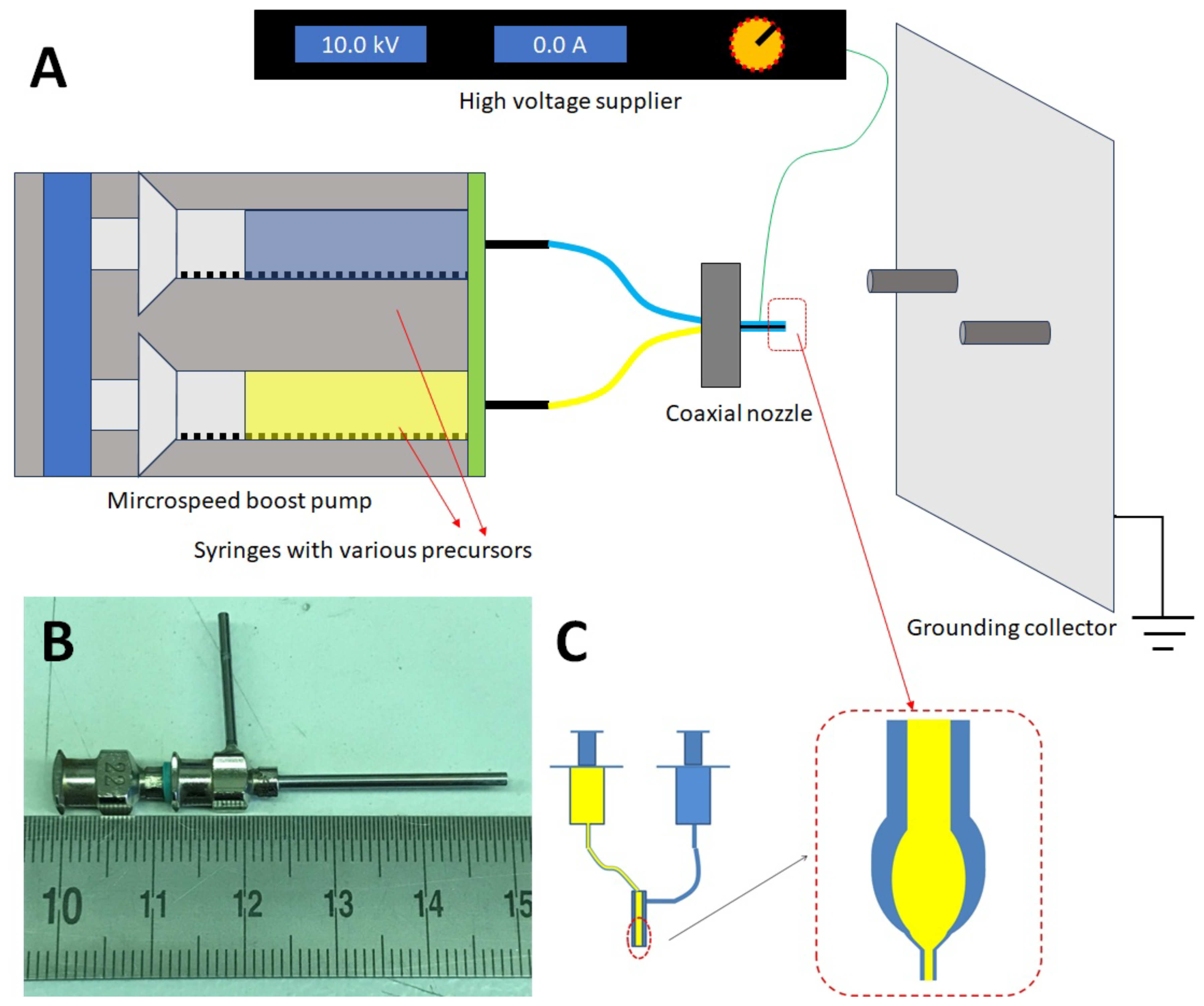
2.1. Preparation of Coaxial Nanowires

The fabrication of all the nanowires is achieved through the sol-gel electrospinning method, employing commercially available chemicals from Alfa Aesar GmbH (Ward Hill, MA, USA). All the chemicals are above analytical grade. To prepare the CoFe 2 O 4 precursor, cobalt acetate (Co(CH 3 COO) 2 · 4H 2 O) and iron nitrite (Fe(NO) 3 · 9H 2 O) are weighted in the molar ratio Co:Fe = 1:2 and dissolved in deionized water, the polymer polyvinylpyrrolidone (PVP) (MW 130,000) is then mixed with solution as to increase the viscosity of the precursor, preparing for the following electrospinning process. Table 1 listed the precursor recipes of all the required chemical phases in this work.
To fabricate coaxial nanowires, we utilize a specially designed electrospinning setup, as shown in Figure 1A. During the electrospinning process, the core precursor and shell precursor are housed in separate syringes, both driven by the same microspeed boost pump. The syringes are coupled to a coaxial nozzle (Figure 1B). When the two different precursors emerge at the end of the nozzle, they form a core-shell liquid sphere as shown in (Figure 1C). Upon applying high voltage to the outer nozzle, the core-shell sphere becomes ionized and morphs into a coaxial jet under the influence of the electric field force between the high voltage nozzle and the grounding collector. Consequently, the coaxial fibers are drawn and collected on the collector. Subsequent thermal treatment at 650 °C yields the desired phase configuration in the coaxial nanowires.

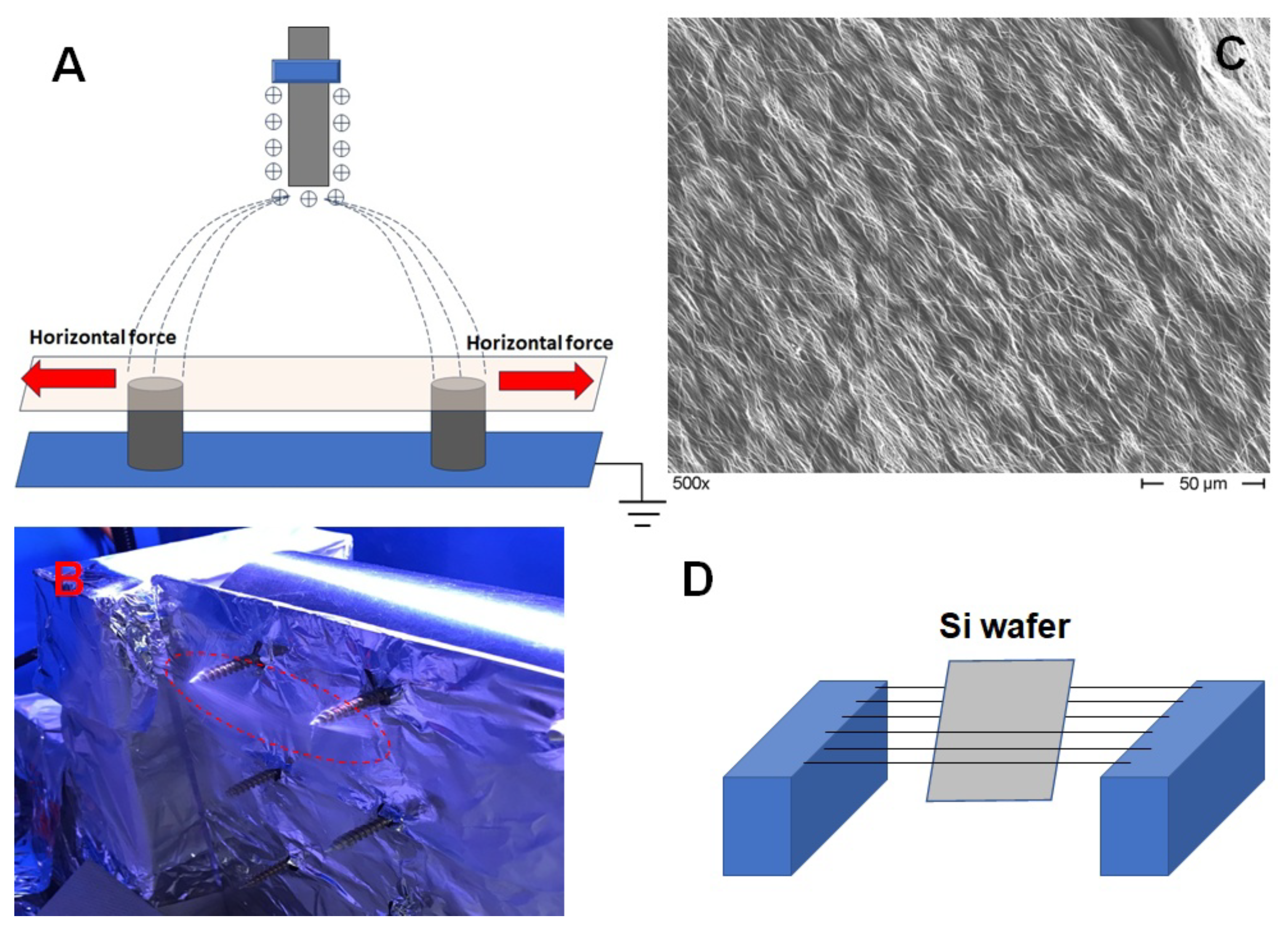
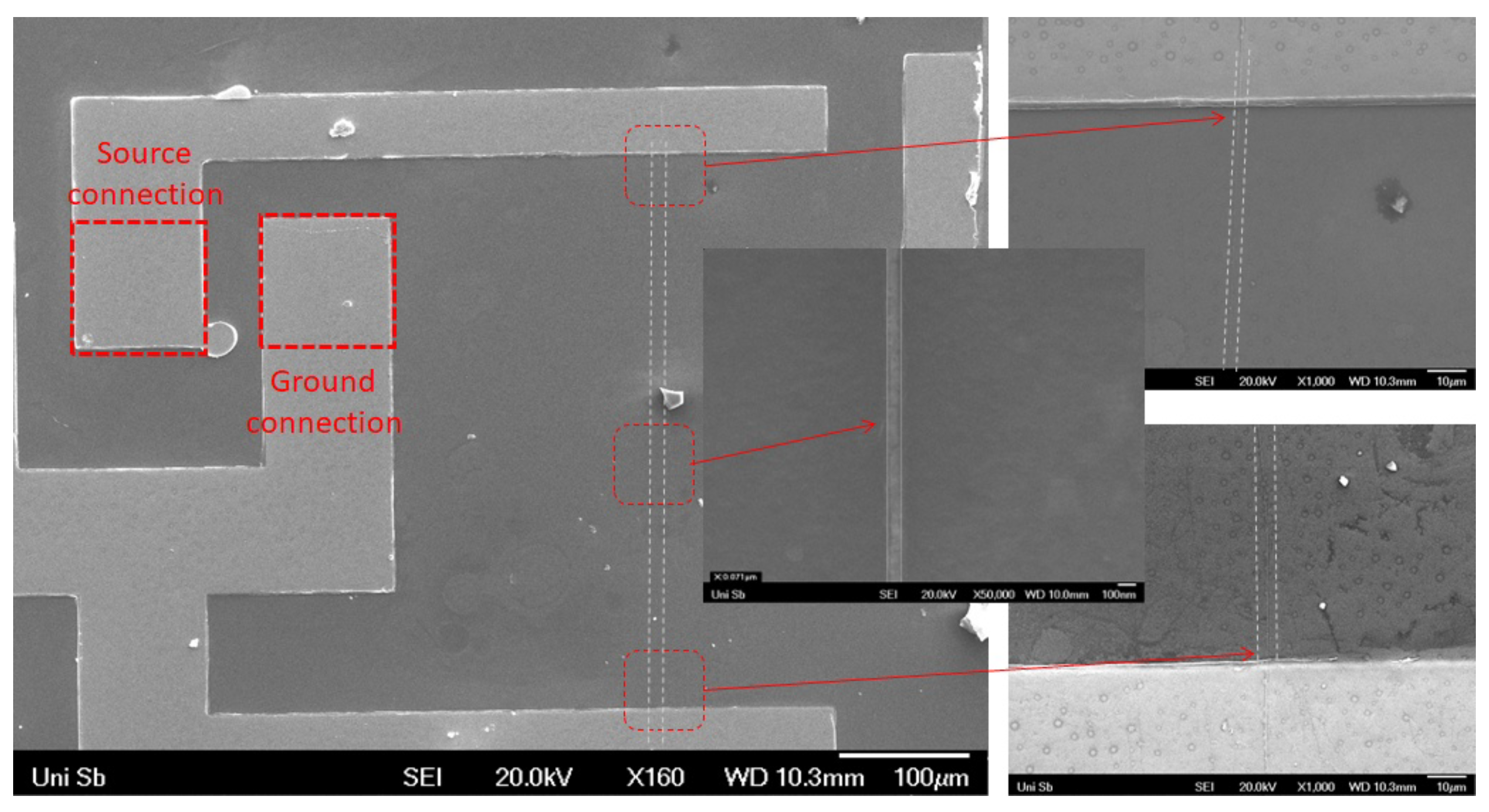
2.2. Sample Preparation for the Magnetic Impedance Measurement

Typically, the collected electrospun nanowires are randomly distributed. To conduct magnetic impedance measurements on these nanowires, it becomes necessary to align them. This alignment can be accomplished through the electric field distribution on the collection area of the electrospinning setup. Two vertical supports are affixed to the grounded collector. Owing to the disparity in vertical positions between the upper extremity of the support and the plane of collection, the electrostatic field undergoes a rearrangement as illustrated in Figure 2A. This rearrangement prompts the emergence of a lateral force within the region encompassing the upper portions of the supports, inducing the alignment of charged fibers in consonance with the lateral force vector, as depicted in Figure 2B. Subsequent, employing a silicon wafer positioned in alignment with the direct path connecting the two supports, it is foreseeable that the orientation of the silicon wafer’s plane will coincide with the established fiber alignment. Consequently, the act of ’gathering’ the fibers possessing the desired alignment becomes achievable (as shown in Figure 2D) through the adhesion of the wafer to the fibers.
In the subsequent stage, we employ Laser lithography ( μ pg 101 from Heidelberg Instruments) to write an electric connection pattern on the aligned nanowires. Due to the precise alignment of the nanowires, when we overlay the electrode onto the nanowires with matching orientation, it is possible that the electrodes uniformly draping over the parallel nanowires, avoiding any form of nanowire intersection. It’s even conceivable for a solitary nanowire to align itself between the electrodes. This simplified arrangement facilitates subsequent analysis in contrast to the intricate network of nanowires. Subsequently, a 300 nm copper layer is deposited by sputtering on the nanowires to form electrodes in the pattern shown in Figure 3. The electrodes contact the ends of the nanowire (Given the discernible difference in size between the electrode and the nanowire, as illustrated in the inset image, we introduce dashed lines to indicate the precise nanowire location).
To conduct magnetic impedance measurements on the nanowires, we utilize a vector analyzer (Rohde und Schwarz ZNL-3) featuring a three-pin connection. According to this setup, the upper part of the electrode serves as the ground connection, while the bottom part is designated for the source connection.

2.3. Remaining Experimental Details

The chemical phases of the samples were identified using a high-resolution automated RINT2200 X-ray powder diffractometer (Rigaku smart-lab, Wilmington, MA, USA) with Cu-K α radiation (40 kV, 40 mA, λ k α 1 = 1.5406 A ˙ , λ k α 2 = 1.5444 A ˙ ). The microstructure characterization involved SEM imaging with a Hitachi S800 (Hitachi, Tokyo, Japan) at 10 kV and TEM analysis using JEOL JSM-7000 F (JEOL, Tokyo, Japan) with 200 kV and LaB 6 cathode, which also included EDAX element analysis. For magnetic property characterization, the samples were examined via PPMS (Quantum Design 6000 (Quantum Design, San Diego, CA, USA)).

3. Results and Discussion

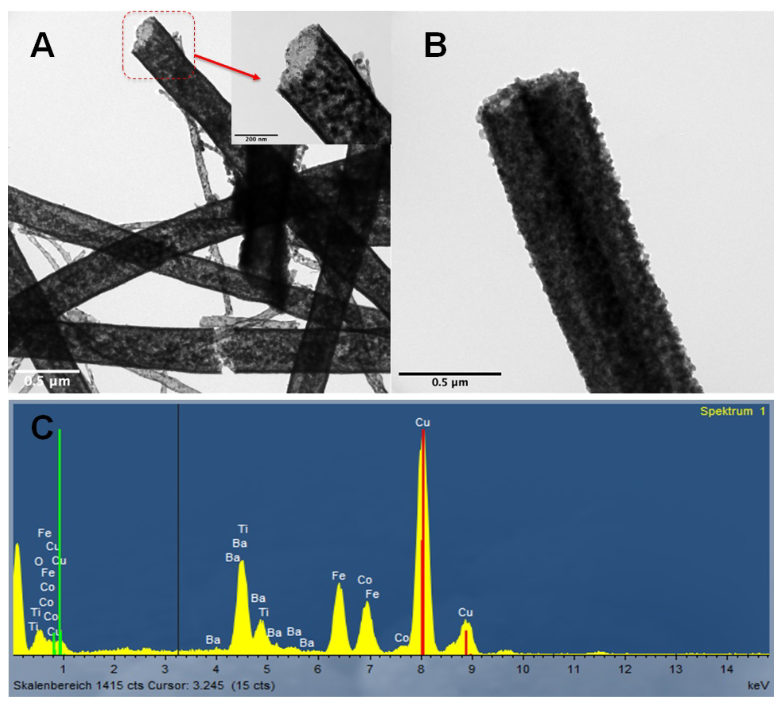
3.1. Microstructure of the Samples

To evaluate the suitability of the coaxial nozzle for coaxial nanowire fabrication, we initially utilized BaTiO 3 precursor as the shell material, while the core precursor consisted of a mixture of PVP and propionic acid. As illustrated in Figure 4A, the organic component underwent decomposition and evaporation during the thermal treatment, resulting in the formation of BaTiO 3 nanotubes with the desired perfect shape. In comparison, the CoFe 2 O 4 @BaTiO 3 coaxial nanowires exhibit a completely solid appearance as shown in Figure 4B. Both the BaTiO 3 nanotubes and CoFe 2 O 4 @BaTiO 3 coaxial nanowires have average diameters of approximately 200 nm. According to the analysis of the XRD refinement data and the observation from TEM, the average grain size of the coaxial nanowires ranges from 20 nm to 50 nm. The grain size appears to be excessively large to sustain superparamagnetism [16].

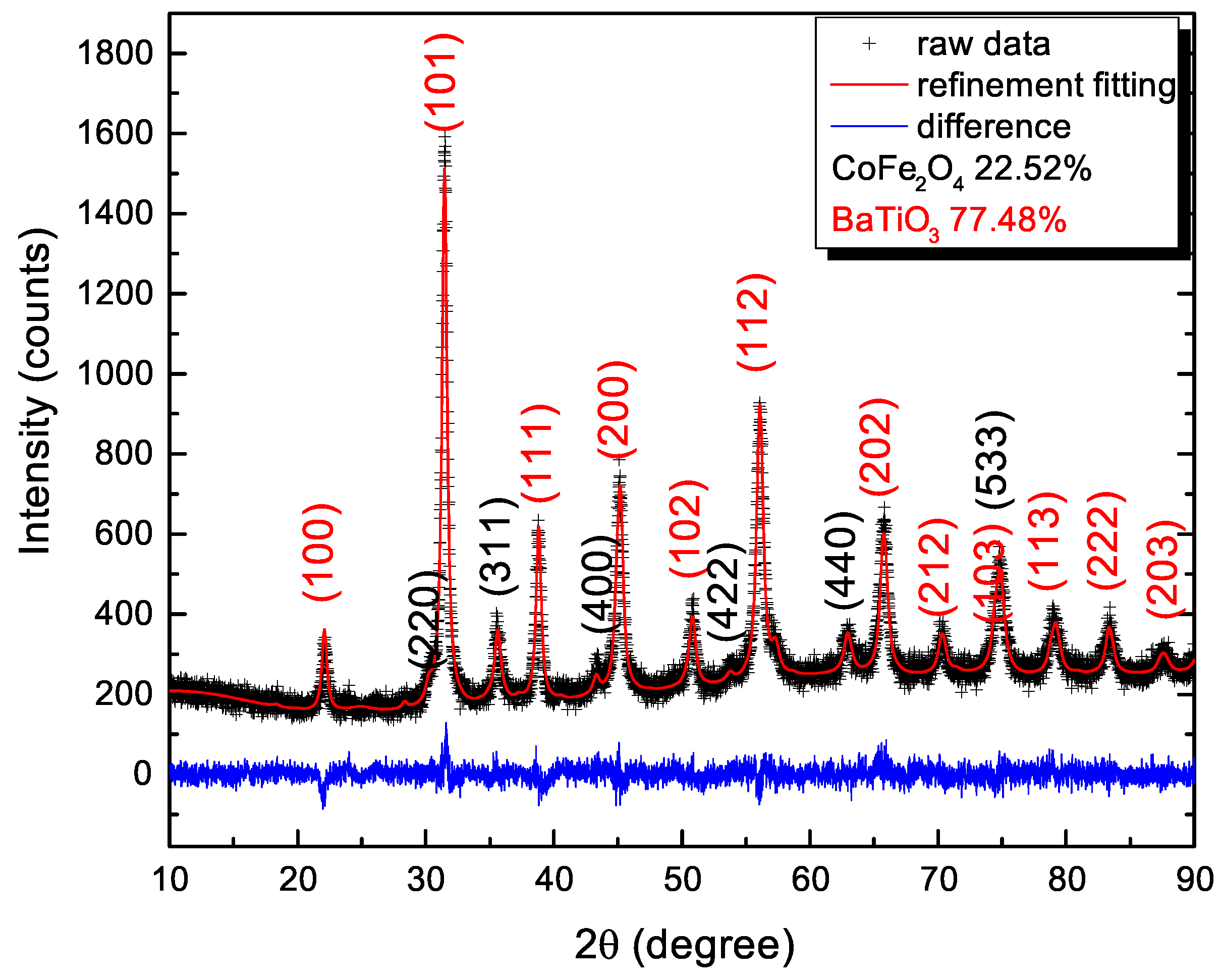
3.2. Phase Analysis of the Coaxial Nanowires

Figure 4C displays the EDAX analysis results of the coaxial nanowires, indicating an atomic ratio of Co:Fe:Ba:Ti = 16.23:30.35:28.02:25.40. This confirms the presence of both CoFe 2 O 4 and BaTiO 3 phases in the coaxial nanowires, with an approximate molar ratio of 1:2. Furthermore, Figure 5 presents the XRD pattern of the coaxial nanowires, providing additional evidence for the existence of both CoFe 2 O 4 and BaTiO 3 phases. The XRD refinement analysis reveals a mass ratio between the two phases as 22.52:77.48, which, when converted to a molar ratio, becomes 22.41:77.59. The higher ratio of BaTiO 3 phase can be attributed to its shell configuration on the nanowires, as the XRD diffraction signals mainly originate from the surface. Considering this aspect, the phase ratio estimated from EDAX analysis is deemed more reliable.

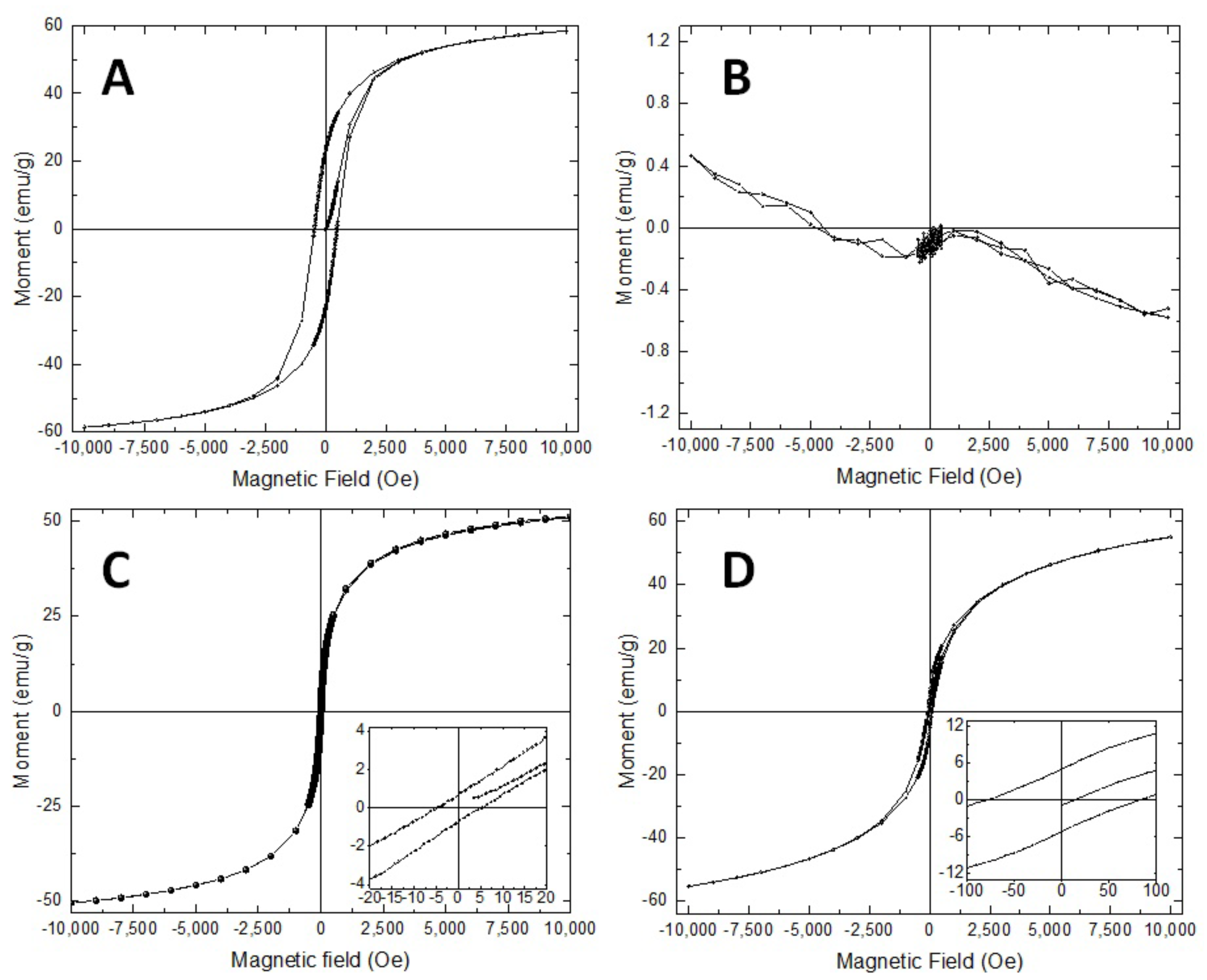
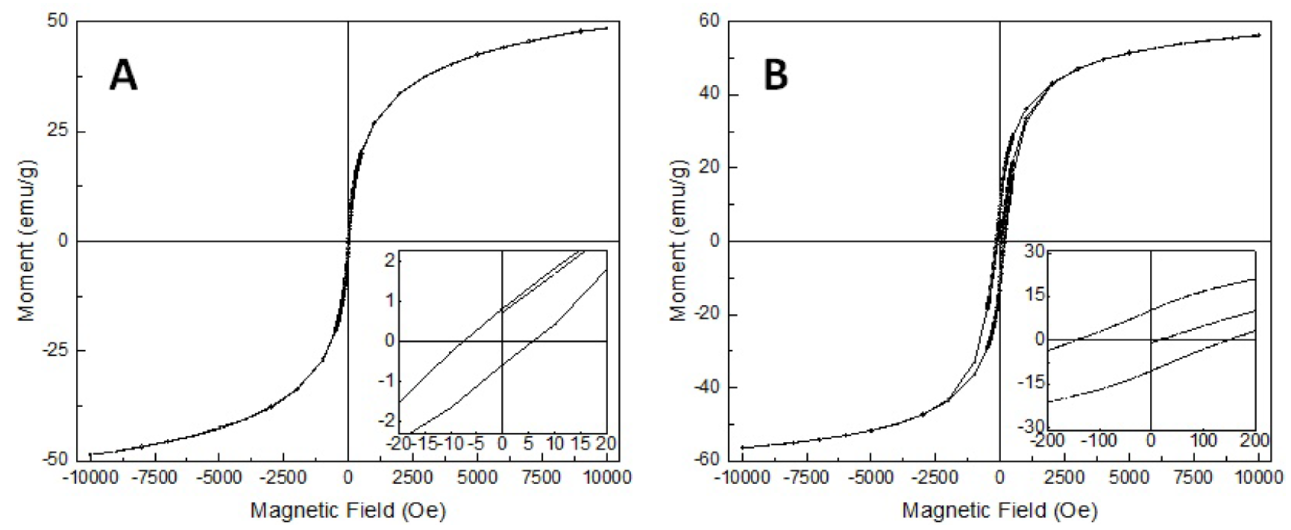
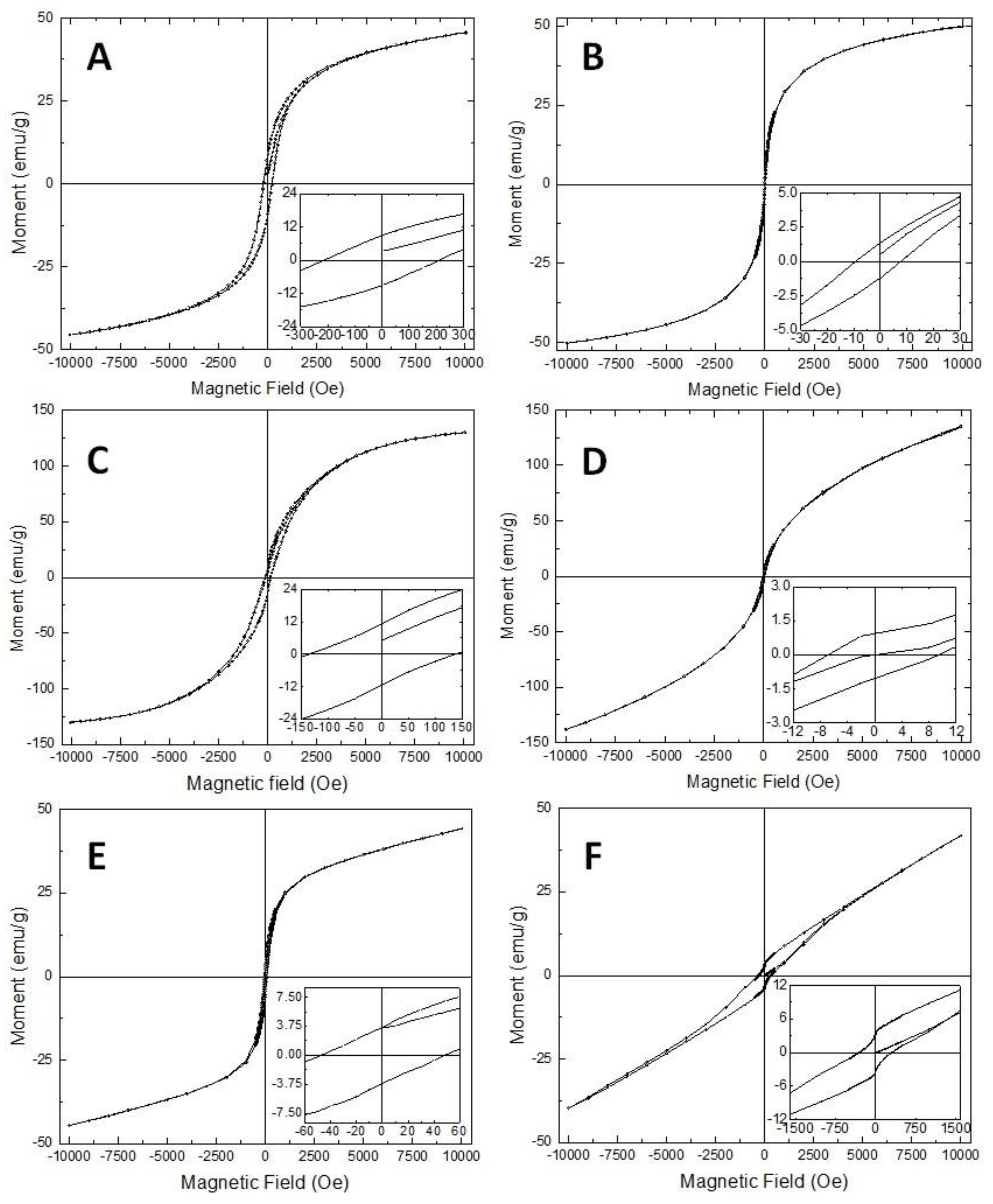
3.3. Magnetic Properties of the Samples

Figure 6A illustrates the M(H) magnetization loop of the pure CoFe 2 O 4 nanowires at 295 K, exhibiting a coercivity ( H C ) of 468 Oe, with the saturation field at 4700 Oe. When compared to the electrospun CoFe 2 O 4 nanowires from another study [27], the coercivity of these nanowires is relatively lower, possibly due to lattice defects induced during the thermal treatment. Nevertheless, these nanowires still fall into the category of ’hard magnetic’ materials.
Figure 6B illustrates the M(H) magnetization loop of pure BaTiO 3 nanowires at 295 K. Initially, a pronounced paramagnetic signal is noticeable. Upon a more detailed examination at lower external magnetic fields, a subtle ferromagnetic component becomes evident. This behavior is of particular interest due to previous reports indicating the presence of ferromagnetic order within nanoscale BaTiO 3 [28,29]. This ferromagnetism is ascribed to intrinsic defects, which gain prominence in smaller grain sizes. Studies in [29], focused on BaTiO 3 nanoparticles with an average size of approximately 21 to 24 nm, have highlighted this phenomenon. Our BaTiO 3 nanottubes, as observed through TEM, exhibit an average grain size of around 20 nm. As a result, we attribute the observed weak ferromagnetic behavior in our BaTiO 3 nanotubes to the emergence of lattice defects within grains during the thermal treatment, as the as-prepared fibers transform into inorganic fibers. However, as a general assumption, we maintain the notion that BaTiO 3 nanotubes exhibit paramagnetism in magnetic measurements.
Surprisingly, a striking transformation occurs when a paramagnetic shell of BaTiO 3 is introduced. As depicted in Figure 6C, the coercivity of the CoFe 2 O 4 @BaTiO 3 coaxial nanowires reduces significantly to 5 Oe, and the saturation field is now at 495 Oe. In essence, the incorporation of a BaTiO 3 shell causes a shift from hard magnetic to soft magnetic behavior in the CoFe 2 O 4 nanowires.
As previously discussed, the reduction of coercivity in these coaxial nanowires cannot be explained solely by the superparamagnetic effect. Instead, the CoFe 2 O 4 @BaTiO 3 coaxial nanowire can be seen as a multilayer system, with paramagnetic (PM) layers (BaTiO 3 ) at the top and bottom, and a ferromagnetic (FM) layer (CoFe 2 O 4 ) at the center. When an external magnetic field is applied to the system, the magnetizations of the different layers align parallel to the field direction. However, when the external magnetic field opposes the magnetization of the FM region, the PM region develops a magnetic moment proportional to its susceptibility. These induced moments decay exponentially with distance away from the interfaces [25]. In this configuration, the magnetization of the FM region becomes antiparallel to the induced PM magnetization. Such a setup is energetically unfavorable, leading to an increase in the interlayer exchange energy. Interestingly, this energy facilitates the magnetization reversal process of the FM region, favoring the parallel alignment of the magnetizations of the PM and FM regions. Consequently, a reduction in the coercivity field is observed. Based on this analysis, it becomes evident that the interface energy plays a crucial role in assisting the magnetization reversal process of the FM region, especially when the magnetization of the FM region and the external magnetic field are opposite to each other.
For comparison, we attempted to exchange the core material to BaTiO 3 while the shell material became CoFe 2 O 4 , resulting in a coercivity ( H C ) of 79 Oe for the new coaxial nanowires as shown in Figure 6D. The reduction of coercivity still persists, although it is not as pronounced as in the previous configuration. This is attributed to the system transforming into an FM/PM/FM multilayer setup, where the magnetization reversal process is constrained by the presence of the shell FM layer.
In our further investigation, we sought to understand the magnetization behavior of the coaxial nanowires as we varied the phase ratio. Achieving this was simple by decreasing the BaTiO 3 concentration in the corresponding precursor. Figure 7 presents the magnetization results of the coaxial nanowires with different phase ratios. When CoFe 2 O 4 :BaTiO 3 = 1:1 (Figure 7A), the coercivity of the samples remained small at H C = 6.7 Oe. However, this value increased to 146.3 Oe when the molar ratio of the BaTiO 3 phase was halved. This observation indicates that as the ratio of the BaTiO 3 phase decreases, the magnetization reversal effect from the FM/PM interface weakens progressively. This explains why in the work of Raidongia et al., the coaxial nanowires synthesized via hydrothermal treatment exhibited a coercivity comparable to pure CoFe 2 O 4 nanowires [21]. The low ratio of BaTiO 3 phase led to the absence of the magnetization reversal effect.
In the subsequent stage, we aimed to investigate whether the magnetization reversal effect was specific to CoFe 2 O 4 @BaTiO 3 coaxial nanowires or not. To explore this, we replaced the core material of CoFe 2 O 4 with NiFe 2 O 4 and Fe 2 O 3 , and then measured the magnetization behavior of the newly formed coaxial nanowires. As depicted in Figure 8A–D, the NiFe 2 O 4 nanowires exhibited a coercivity of 210 Oe. However, upon adding a BaTiO 3 shell, the coercivity reduced significantly to 9.5 Oe. A similar trend was observed with the Fe 2 O 3 nanowires, where the coercivity decreased from 133 Oe to 8.5 Oe after incorporating a BaTiO 3 shell.
Through occasional attempts, we made an intriguing discovery that BaTiO 3 is not the sole material capable of serving as the paramagnetic (PM) layer for magnetization reversal in the coaxial nanowire system. As demonstrated in Figure 8E, a noticeable reduction in coercivity also occurs with the GdBa 2 Cu 3 O 7 shell ( H C = 48 Oe). At 5 K, the hysteresis loop of the CoFe 2 O 4 @GdBa 2 Cu 3 O 7 coaxial nanowires displays a ferromagnetic loop. However, it is evident that the shape of the hysteresis loop is influenced by the superconducting component, as shown in the inset of Figure 8F.

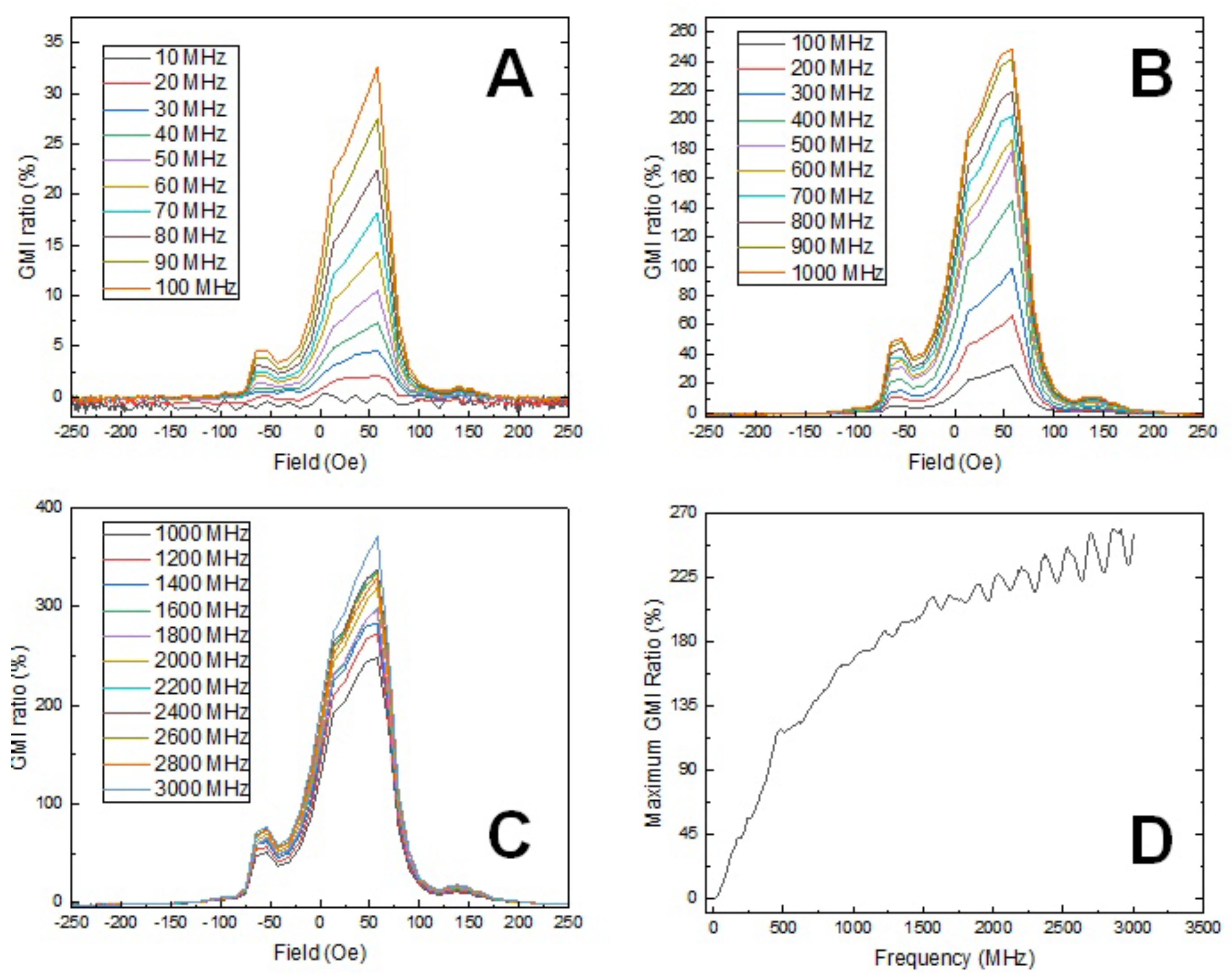
3.4. Magnetic Impedance Measurement of the Coaxial Nanowires

Figure 9 illustrates the magnetic impedance results of the CoFe 2 O 4 @BaTiO 3 coaxial nanowires across the frequency range from 10 MHz to 3 GHz. At 20 MHz, a single peak emerges with a maximum at 57.5 Oe, and the ratio increases with frequency up to 370% at 3 GHz. Another peak appears at 40 MHz, reaching a maximum at −53.8 Oe, and its ratio increases with frequency up to 77% at 3 GHz.
Consider a sample with its magnetic easy axis oriented along the wire’s length. In this context, applying both the current and magnetic field along the wire results in a singular peak. This outcome is a consequence of the peak transverse permeability emerging at H = 0. Conversely, in the opposite scenario where the magnetization stands perpendicular to the wire’s length, while the current is parallel to the wire, a double peak pattern emerges. This phenomenon finds its peak at the anisotropy field. These two peaks correspond to the ferromagnetic resonances, manifesting in both the saturated and non-saturated states [30]. When an angle between the field and the magnetic easy axis exists, the magnetization undertakes a rotation in alignment with this angle. This rotation precipitates an impedance increase.
In our experimental setup, the magnetic field is applied perpendicular to the electric connection pattern. The small misalignment of the nanowire (not precisely perpendicular to the connected pattern (as shown in right images of Figure 3)) causes an angle between the current and external field. The lateral component of the magnetization in relation to the current induces the appearance of a secondary peak. The asymmetry in the experimental peak heights can be attributed to the presence of non-diagonal components within the impedance tensor, as clarified in [30]. Moreover, since the wire is not field treated, the magnetization becomes randomly oriented.
In conclusion, the nanowires exhibit a high Giant Magnetoimpedance (GMI) ratio that can be utilized for magnetic field sensing. However, the preferred configuration is the double peak, as the linear range between those two peaks can be employed. To achieve this, the following strategies can be employed: 1. Preparing the nanowires with an external field perpendicular to the length dimension during heat treatment. This approach amplifies the lateral component of magnetization, rendering the impedance more conducive to the emergence of double peaks; 2. Inducing helical anisotropy through joule heating. This technique prevents the magnetic hardening often observed during traditional furnace annealing, facilitating substantial enhancement in GMI performance [31].

4. Conclusions

In this study, we investigated the magnetization behavior and properties of CoFe 2 O 4 @BaTiO 3 coaxial nanowires, along with their variations when different core materials were used. Our findings revealed a remarkable reduction in coercivity when a BaTiO 3 shell was introduced to the CoFe 2 O 4 core, leading to a shift from hard magnetic to soft magnetic behavior. This intriguing magnetization reversal effect was also observed when GdBa 2 Cu 3 O 7 was used as the shell material. Additionally, we explored the impact of different phase ratios on the coercivity, further validating the significance of the PM layer in the nanowires’ magnetic behavior.
Moreover, we discovered that the misalignment of the nanowire affected the observed magnetic impedance behavior, leading to the emergence of multiple peaks. We suggested possible approaches, such as external field treatment or inducing helical anisotropy, to optimize the configuration and utilize the double peak for magnetic field sensing.
Throughout the investigation, our research sheds light on the versatile characteristics of coaxial nanowires and their promising applications, especially in the realm of magnetic field sensing.

Author Contributions

Conceptualization, X.-L.Z.; methodology, X.-L.Z.; validation, U.H.; investigation, X.-L.Z., I.S.; resources, U.H.; data curation, X.-L.Z.; writing–original draft preparation, X.-L.Z.; supervision, U.H. All authors have read and agreed to the published version of the manuscript.

Funding

This research received no external funding.

Data Availability Statement

The data that support the findings of this study are available from the corresponding author, [Xian-Lin Zeng], upon reasonable request.

Conflicts of Interest

The authors declare no conflict of interest.

References

  1. Jin, S.; Tiefel, T.H.; McCormack, M.; Fastnacht, R.A.; Ramesh, R.; Chen, L.H. Thousandfold change in resistivity in magnetoresistive La-Ca-Mn-O films. Science 1994, 264, 413–415. [Google Scholar] [CrossRef] [PubMed]
  2. Rodriguez, L.M.; Attfield, J.P. Cation disorder and size effects in magnetoresistive manganese oxide perovskites. Phys. Rev. B 1996, 54, R15622–R15625. [Google Scholar] [CrossRef] [PubMed]
  3. Ramirez, A.P. Colossal magnetoresistance. J. Phys. Condens. Matter 1997, 9, 8171–8199. [Google Scholar] [CrossRef]
  4. Mathew, D.S.; Juang, R.-S. An overview of the structure and magnetism of spinel ferrite nanoparticles and their synthesis in microemulsions. Chem. Eng. J. 2007, 129, 51–65. [Google Scholar] [CrossRef]
  5. Naseri, M.G.; Saion, E.B.; Ahangar, H.A.; Shaari, A.H.; Hashim, M. Simple Synthesis and Characterization of Cobalt Ferrite Nanoparticles by a Thermal Treatment Method. J. Nanomater. 2010, 2010, 907686. [Google Scholar]
  6. Patil, D.R.; Chougule, B.K. Effect of copper substitution on electrical and magnetic properties of NiFe2O4 ferrite. Mater. Chem. Phys. 2009, 117, 35–40. [Google Scholar] [CrossRef]
  7. Fan, H.M.; Yi, J.B.; Yang, Y.; Kho, K.W.; Tan, H.R.; Shen, Z.X.; Ding, J.; Sun, X.W.; Olivo, M.C.; Feng, Y.P. Single-Crystalline MFe2O4 Nanotubes/Nanorings Synthesized by Thermal Transformation Process for Biological Applications. ACS Nano 2009, 3, 2798–2808. [Google Scholar] [CrossRef]
  8. Laokul, P.; Arthan, S.; Maensiri, S.; Swatsitang, E. Magnetic and Optical Properties of CoFe2O4 Nanoparticles Synthesized by Reverse Micelle Microemulsion Method. J. Supercond. Nov. Magn. 2015, 28, 2483–2489. [Google Scholar] [CrossRef]
  9. Koseoglu, Y.; Alan, F.; Tan, M.; Yilgin, R.; Ozturk, M. Low temperature hydrothermal synthesis and characterization of Mn doped cobalt ferrite nanoparticles. Ceram. Int. 2012, 38, 3625–3634. [Google Scholar] [CrossRef]
  10. Bhame, S.D.; Joy, P.A. Tuning of the magnetostrictive properties of CoFe2O4 by Mn substitution for Co. J. Appl. Phys. 2006, 100, 113911. [Google Scholar] [CrossRef]
  11. Koseoglu, Y.; Baykal, A.; Gozuak, F.; Kavas, H. Structural and magnetic properties of CoxZn1−xFe2O4 nanocrystals synthesized by microwave method. Polyhedron 2009, 28, 2887–2892. [Google Scholar] [CrossRef]
  12. Kasapoglu, N.; Birsoz, B.; Baykal, A.; Koseoglu, Y.; Toprak, M.S. Synthesis and magnetic properties of octahedral ferrite NixCo1−xFe2O4 nanocrystals. Cent. Eur. J. Chem. 2007, 5, 570–580. [Google Scholar]
  13. Moradmard, H.; Farjami Shayesteh, S.; Tohidi, P.; Abbas, Z.; Khaleghi, M. Structural, magnetic and dielectric properties of magnesium doped nickel ferrite nanoparticles. J. Alloys Compd. 2015, 650, 116–122. [Google Scholar] [CrossRef]
  14. Zhou, B.; Zhang, Y.W.; Liao, C.S.; Yan, C.H. Magnetism and phase transition for CoFe2−xMnxO4 nanocrystalline thin films and powders. J. Magn. Magn. Mater. 2002, 247, 70–76. [Google Scholar] [CrossRef]
  15. Chae, K.P.; Lee, J.-G.; Kweon, H.S.; Lee, Y.B. The crystallographic, magnetic properties of Al, Ti doped CoFe2O4 powders grown by sol-gel method. J. Magn. Magn. Mater. 2004, 283, 103–108. [Google Scholar] [CrossRef]
  16. Virden, A.; Wells, S.; O’Grady, K. Physical and magnetic properties of highly anisotropic cobalt ferrite particles. J. Magn. Magn. Mater. 2007, 316, e768–e771. [Google Scholar] [CrossRef]
  17. Mahmoudi, M.; Sant, S.; Wang, B.; Laurent, S.; Sen, T. Superparamagnetic iron oxide nanoparticles (SPIONs): Development, surface modification and applications in chemotherapy. Adv. Drug Deliv. Rev. 2011, 63, 24–46. [Google Scholar] [CrossRef]
  18. Lu, X.; Liang, G.; Sun, Q.; Yang, C. High-frequency magnetic properties of Ni-Zn ferrite nanoparticles synthesized by a low temperature chemical method. Mater. Lett. 2011, 65, 674–676. [Google Scholar]
  19. Zheng, H.; Wang, J.; Lofland, S.E.; Ma, Z.; Mohaddes-Ardabili, L.; Zhao, T.; Salamanca-Riba, L.; Shinde, S.R.; Ogale, S.B.; Bai, F.; et al. Multiferroic BaTiO3-CoFe2O4 Nanostructures. Science 2004, 303, 661–663. [Google Scholar] [CrossRef]
  20. Duong, G.V.; Groessinger, R. Effect of preparation conditions on magnetoelectric properties of CoFe2O4–BaTiO3 magnetoelectric composites. J. Magn. Magn. Mater. 2007, 316, e624–e627. [Google Scholar] [CrossRef]
  21. Raidongia, K.; Nag, A.; Sundaresan, A.; Rao, C.N.R. Multiferroic and magnetoelectric properties of core-shell CoFe2O4@BaTiO3 nanocomposites. Appl. Phys. Lett. 2010, 97, 062904. [Google Scholar] [CrossRef]
  22. Lu, X.; Kim, Y.; Goetze, S.; Li, X.; Dong, S.; Werner, P.; Alexe, M.; Hesse, D. Magnetoelectric Coupling in Ordered Arrays of Multilayered Heteroepitaxial BaTiO3/CoFe2O4 Nanodots. Nano Lett. 2011, 11, 3202–3206. [Google Scholar] [CrossRef] [PubMed]
  23. Bauer, M.J.; Wen, X.; Tiwari, P.; Arnold, D.P.; Andrew, J.S. Magnetic field sensors using arrays of electrospun magnetoelectric Janus nanowires. Microsyst. Nanoeng. 2018, 4, 37. [Google Scholar] [CrossRef] [PubMed]
  24. Erdem, D.; Bingham, N.S.; Heiligtag, F.J.; Pilet, N.; Warnicke, P.; Vaz, C.A.F.; Shi, Y.; Buzzi, M.; Rupp, J.L.M.; Heyderman, L.J.; et al. Nanoparticle-Based Magnetoelectric BaTiO3–CoFe2O4 Thin Film Heterostructures for Voltage Control of Magnetism. ACS Nano 2016, 10, 9840–9851. [Google Scholar] [CrossRef]
  25. Fallarino, L.; Quintana, M.; Rojo, E.L.; Berger, A. Suppression of Coercivity in Nanoscale Graded Magnetic Materials. Phys. Rev. Appl. 2021, 16, 034038. [Google Scholar] [CrossRef]
  26. Wang, Y.; Wang, H.; Tan, W.; Huo, D. Magnetization reversal, critical behavior, and magnetocaloric effect in NdMnO3: The role of magnetic ordering of Nd and Mn moments. J. Appl. Phys. 2022, 132, 183907. [Google Scholar] [CrossRef]
  27. Cheng, C.; Dai, J.; Li, Z.; Feng, W. Preparation and magnetic properties of CoFe2O4 oriented fiber arrays by electrospinning. Materials 2020, 13, 3860. [Google Scholar] [CrossRef]
  28. Bahoosh, S.G.; Trimper, S.; Wesselinowa, J.M. Origin of ferromagnetism in BaTiO3 nanoparticles. Phys. Status Solidi RRL 2011, 5, 382–384. [Google Scholar] [CrossRef]
  29. Phan, T.; Zhang, P.; Yang, D.S.; Thanh, T.D.; Tuan, D.A.; Yu, S.C. Origin of ferromagnetism in BaTiO3 nanoparticles prepared by mechanical milling. J. Appl. Phys. 2013, 113, 17E035. [Google Scholar] [CrossRef]
  30. Mansourian, S.; Bakhshayeshi Ali Mendi, R.T. Giant magneto-impedance variation in amorphous CoFeSiB ribbons as a function of tensile stress and frequency. Phys. Lett. A 2020, 384, 126657. [Google Scholar] [CrossRef]
  31. Corte-León, P.; Zhukova, V.; Ipatov, M.; Blanco, J.M.; Zhukov, A. Effect of Joule heating on giant magnetoimpedance effect and magnetic properties of Co-rich microwires. J. Alloys Compd. 2021, 883, 160778. [Google Scholar]
Figure 1. (A) Scheme of coaxial electrospinning setup; (B) Image of the coaxial electrospinning nozzle; (C) Scheme of the formation process of coaxial fiber.
Solids 04 00019 g001
Figure 2. (A) collection setup for aligned nanowires; (B) Image of the practical collection setup, the highlight area shows the collected fibers with specific orientation; (C) SEM image of the aligned nanowreis; (D) approach of transporting aligned nanowires to a silicon wafer.
Solids 04 00019 g002
Figure 3. SEM of the nanowire with electrode for magnetic impedance measurement.
Solids 04 00019 g003
Figure 4. (A) TEM image of the BaTiO 3 nanotubes; (B) TEM image of the CoFe 2 O 4 @BaTiO 3 coaxial nanowire; (C) EDAX analysis of the CoFe 2 O 4 @BaTiO 3 coaxial nanowire. The red and green peaks display the main and subordinate peaks of Cu element from the TEM holding grid.
Solids 04 00019 g004
Figure 5. XRD of the CoFe 2 O 4 @BaTiO 3 coaxial nanowires with XRD refinement and phase analysis.
Solids 04 00019 g005
Figure 6. M(H) magnetization of nanowires at 295 K: (A) CoFe 2 O 4 nanowires; (B) BaTiO 3 nanotubes; (C) CoFe 2 O 4 @BaTiO 3 coaxial nanowires; (D) BaTiO 3 @CoFe 2 O 4 coaxial nanowires.
Solids 04 00019 g006
Figure 7. M(H) magnetization of CoFe 2 O 4 @BaTiO 3 coaxial nanowires with different phase ratio: (A) CoFe 2 O 4 :BaTiO 3 = 1:1; (B) CoFe 2 O 4 :BaTiO 3 = 2:1.
Solids 04 00019 g007
Figure 8. (AD): M(H) magnetization of ferrite nanowires and their corresponding coaxial nanowires: (A) NiFe 2 O 4 nanowire, (B) NiFe 2 O 4 @BaTiO 3 coaxial nanowires, (C) Fe 2 O 3 nanowires, (D) Fe 2 O 3 @BaTiO 3 coaxial nanowires; (E,F): M(H) magnetization of CoFe 2 O 4 @GdBa 2 Cu 3 O 7 coaxial nanowires: (E): 295 K; (F): 5 K.
Solids 04 00019 g008
Figure 9. (AC): Magnetic impedance measurement of the CoFe 2 O 4 @BaTiO 3 coaxial nanowires: (A) 10 MHz–100 MHz, (B) 100 MHz–1 GHz, (C) 1 GHz–3 GHz; (D) Maximum GMI ratio dependance on frequency.
Solids 04 00019 g009
Table 1. List of precursor recipes for the required chemical phase in this work. P.S.:M.R. indicates ‘Molar Ratio’.
Phase Chemicals M.R. Solvent
CoFe 2 O 4 Co(Ac) 2 · 4H 2 OFe(NO) 3 · 9H 2 O 12 water
NiFe 2 O 4 Ni(Ac) 2 · 4H 2 OFe(NO) 3 · 9H 2 O 12 water
Fe 2 O 3 Fe(NO) 3 · 9H 2 O - water
BaTiO 3 Ba(Ac) 2 Ti(C 1 6 H 36 O 4 ) 11 Propionic acid
GdBa 2 Cu 3 O 7 Gd(Ac) 3 · xH 2 OBa(Ac) 2 Cu(Ac) 2 123Propionic acid
Disclaimer/Publisher’s Note: The statements, opinions and data contained in all publications are solely those of the individual author(s) and contributor(s) and not of MDPI and/or the editor(s). MDPI and/or the editor(s) disclaim responsibility for any injury to people or property resulting from any ideas, methods, instructions or products referred to in the content.

