

Greenhouse Gas Conversion into Hydrocarbons and Oxygenates Using Low Temperature Barrier Discharge Plasma Combined with Zeolite Catalysts

Abstract
:1. Introduction
2. Materials and Methods
2.1. Preparation of the Catalysts
2.2. Catalysts Characterization
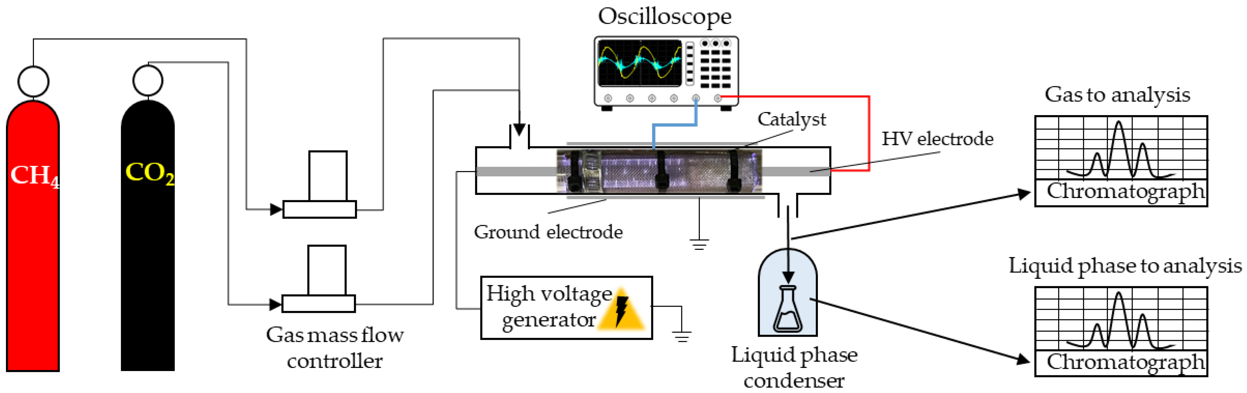
2.3. Plasma-Catalytic Gases Utilization
3. Results and Discussion
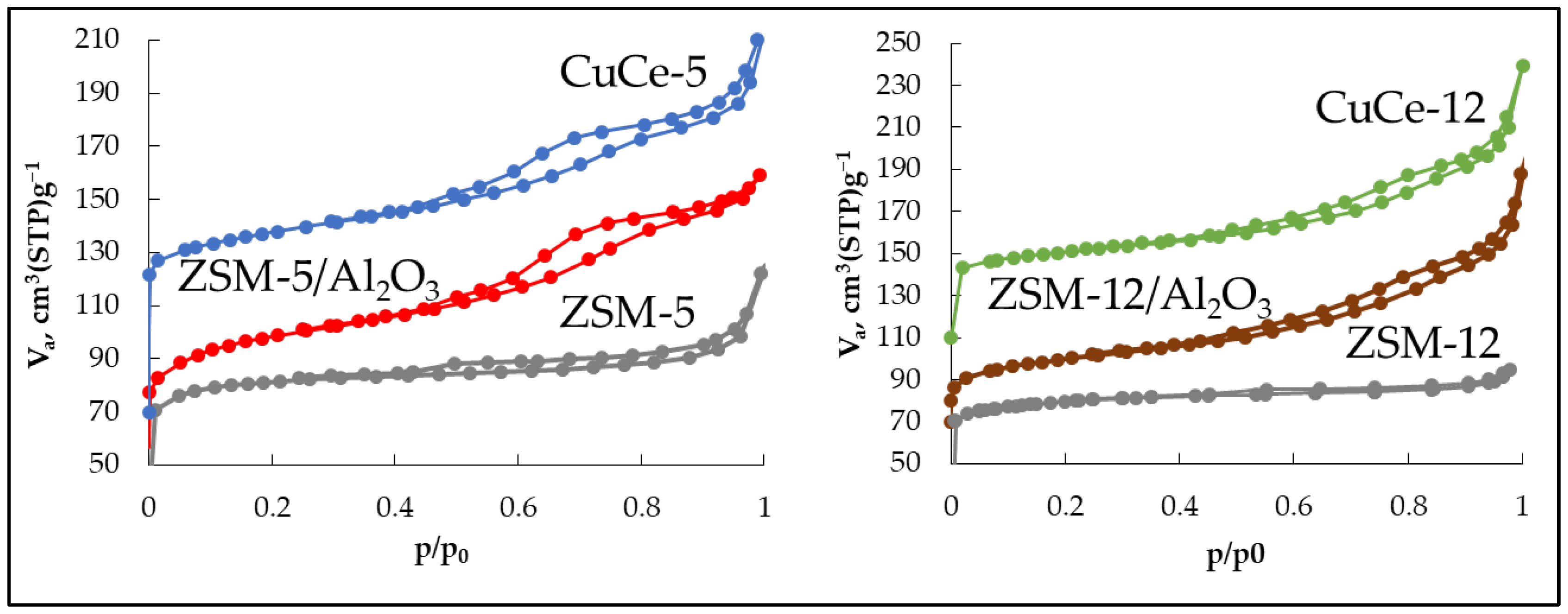
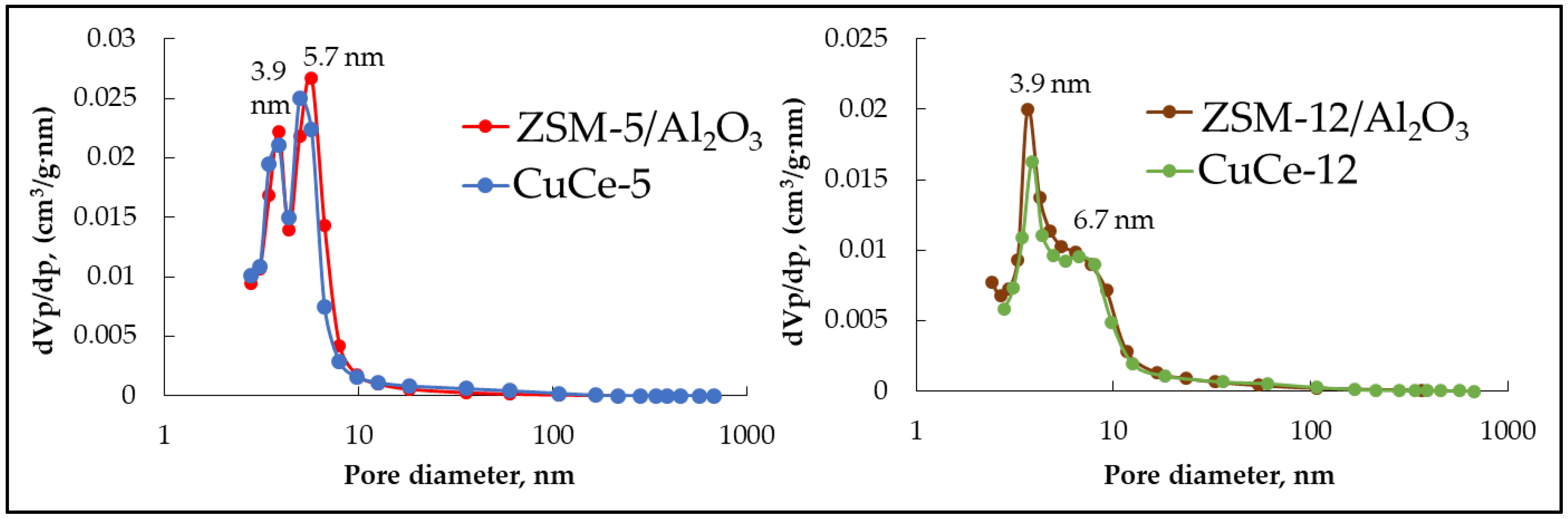
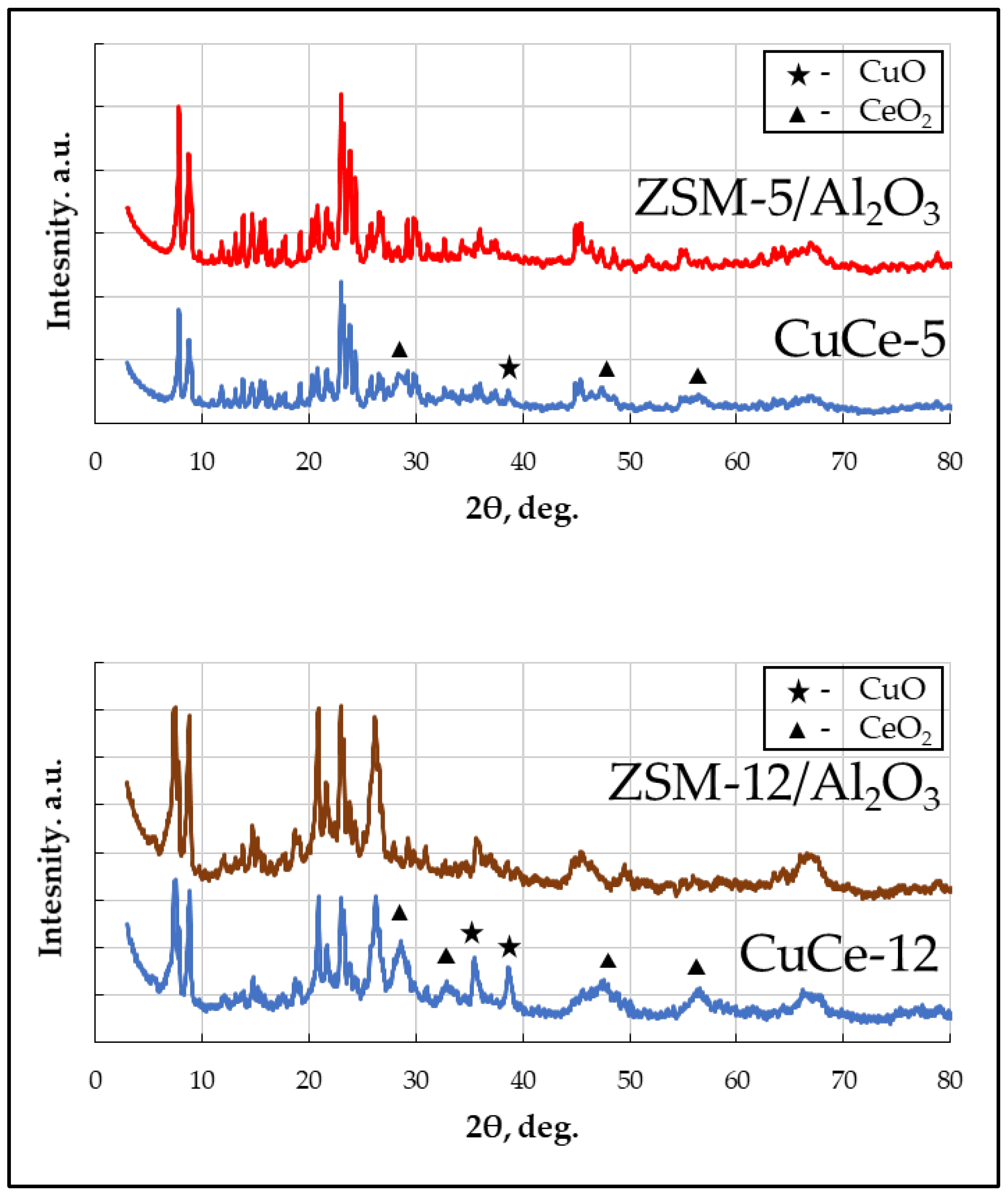
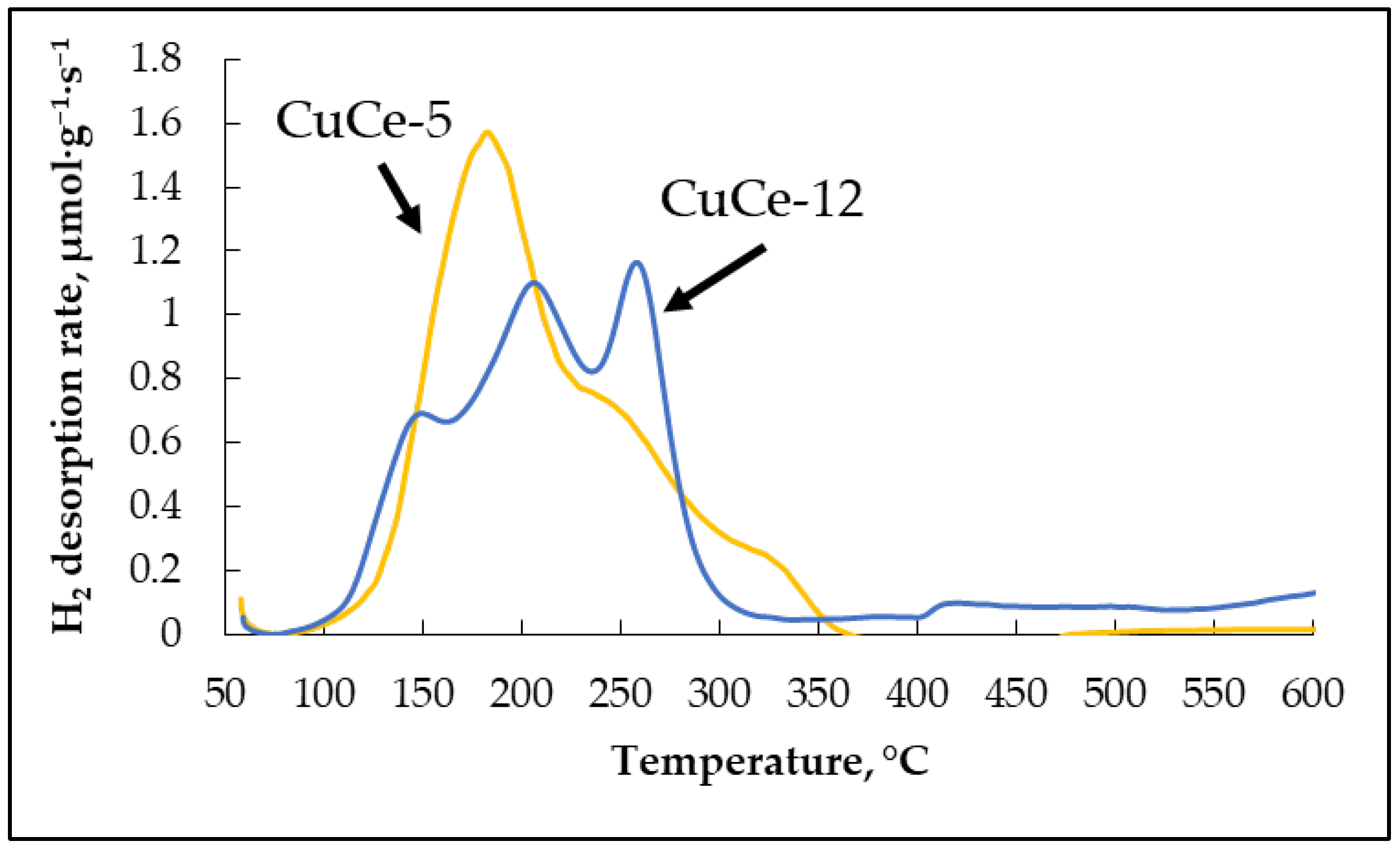
3.1. Zeolite Catalyst Synthesis and Characterization
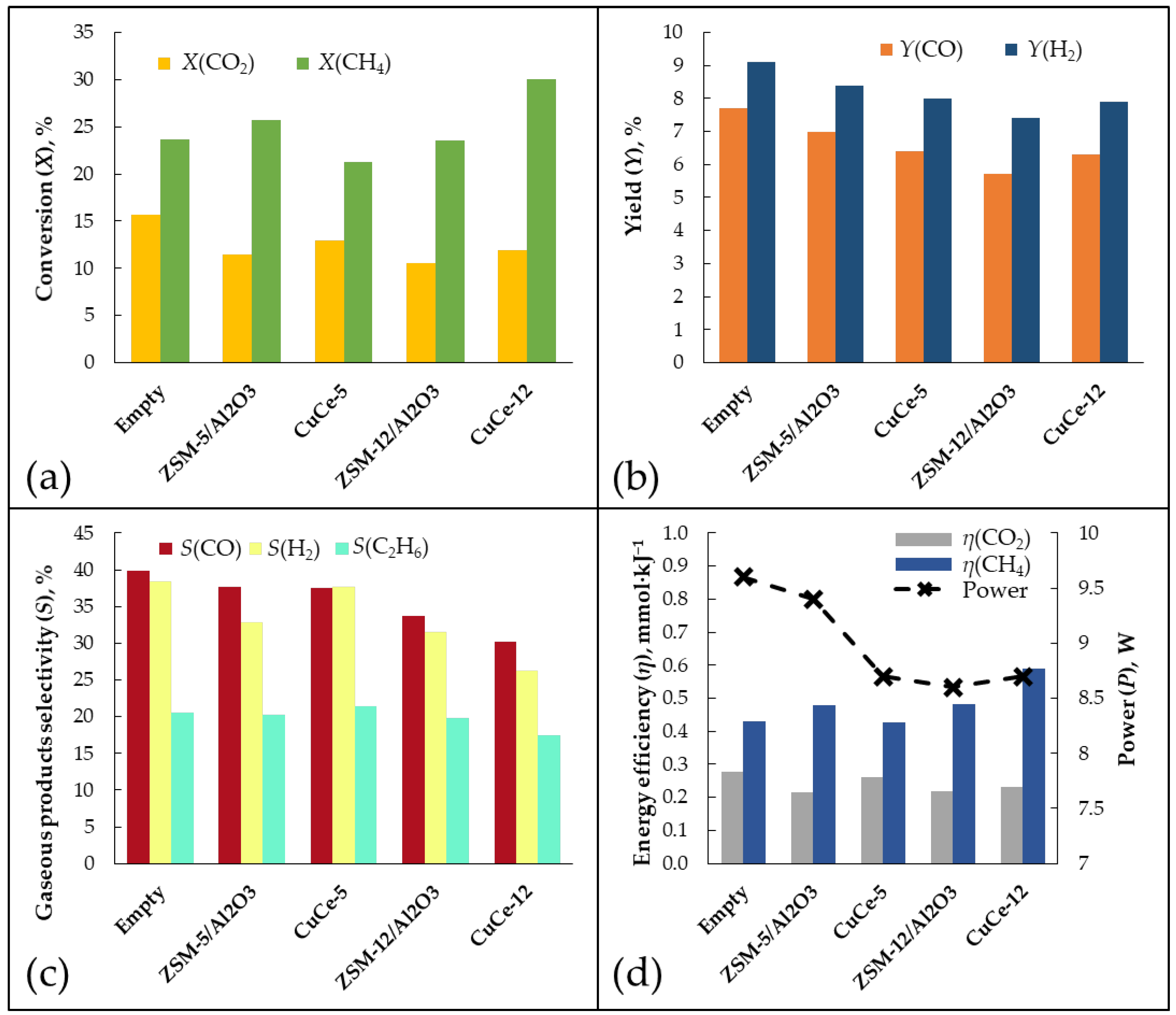
3.2. Gas Conversion Using Plasma-Catalytic Process
4. Conclusions
Author Contributions
Funding
Data Availability Statement
Acknowledgments
Conflicts of Interest
References
- Kostyuchenko, N.; Smolennikov, D. Greenhouse Gas Emissions. In Responsible Consumption and Production; Filho, W.L., Azul, A.M., Brandli, L., Özuyar, P.G., Wall, T., Eds.; Springer: Cham, Switzerland, 2022; pp. 324–335. [Google Scholar] [CrossRef]
- Lalsare, A.; Sivri, A.; Egan, R.; Vukmanovich, R.J.; Dumitrescu, C.E.; Hu, J. Biomass—Flare gas synergistic co-processing in the presence of carbon dioxide for the controlled production of syngas (H2:CO~2–2.5). Chem. Eng. J. 2020, 385, 123783. [Google Scholar] [CrossRef]
- Cai, X.; Hu, Y.H. Advances in catalytic conversion of methane and carbon dioxide to highly valuable products. Energy Sci. Eng. 2019, 7, 4–29. [Google Scholar] [CrossRef]
- Hussien, A.G.S.; Polychronopoulou, K.A. Review on the Different Aspects and Challenges of the Dry Reforming of Methane (DRM) Reaction. Nanomaterials 2022, 12, 3400. [Google Scholar] [CrossRef] [PubMed]
- Lavoie, J.-M. Review on dry reforming of methane, a potentially more environmentally-friendly approach to the increasing natural gas exploitation. Front. Chem. 2014, 2, 81. [Google Scholar] [CrossRef] [PubMed]
- An, Y.; Lin, T.; Yu, F.; Yang, Y.; Zhong, L.; Wu, M.; Sun, Y. Advances in direct production of value-added chemicals via syngas conversion. Sci. China Chem. 2017, 60, 887–903. [Google Scholar] [CrossRef]
- Wender, I. Synthesis Gas as a Source of Fuels and Chemicals: C-1 Chemistry. Annu. Rev. Energy 1986, 11, 295–314. [Google Scholar] [CrossRef]
- Han, J.W.; Park, J.S.; Choi, M.S.; Lee, H. Uncoupling the size and support effects of Ni catalysts for dry reforming of methane. Appl. Catal. B 2017, 203, 625–632. [Google Scholar] [CrossRef]
- Jabbour, K.; El Hassan, N.; Davidson, A.; Massiani, P.; Casale, S. Characterizations and performances of Ni/diatomite catalysts for dry reforming of methane. Chem. Eng. J. 2015, 264, 351–358. [Google Scholar] [CrossRef]
- Zafarnak, S.; Rahimpour, M.R. Co-Ni bimetallic supported on mullite as a promising catalyst for biogas dry reforming toward hydrogen production. Mol. Catal. 2023, 534, 112803. [Google Scholar] [CrossRef]
- Xu, D.-J.; Wu, J.; Liu, Z.; Qiao, L.-Y.; Zong, S.-S.; Zhou, Z.-F.; Yao, Y.-G. Doping low amount of Zirconium in Rh-LTO to prepare durable catalysts for dry reforming of methane. Mol. Catal. 2023, 535, 112822. [Google Scholar] [CrossRef]
- Bai, Y.; Sun, K.; Wu, J.; Zhang, M.; Zhao, S.; Kim, Y.D.; Liu, Y.; Gao, J.; Liu, Z.; Peng, Z. The Ga-promoted Ni/CeO2 catalysts for dry reforming of methane with high stability induced by the enhanced CO2 activation. Mol. Catal. 2022, 530, 112577. [Google Scholar] [CrossRef]
- Kushida, M.; Yamaguchi, A.; Miyauchi, M. Photocatalytic dry reforming of methane by rhodium supported monoclinic TiO2-B nanobelts. J. Energy Chem. 2022, 71, 562–571. [Google Scholar] [CrossRef]
- Tahir, M.; Ali Khan, A.; Bafaqeer, A.; Kumar, N.; Siraj, M.; Fatehmulla, A. Highly Stable Photocatalytic Dry and Bi-Reforming of Methane with the Role of a Hole Scavenger for Syngas Production over a Defective Co-Doped g-C3N4 Nanotexture. Catalysts 2023, 13, 1140. [Google Scholar] [CrossRef]
- Zhang, Z.-Y.; Li, T.; Yao, J.-L.; Xie, T.; Xiao, Q. Mechanism and kinetic characteristics of photo-thermal dry reforming of methane on Pt/mesoporous-TiO2 catalyst. Mol. Catal. 2023, 535, 112828. [Google Scholar] [CrossRef]
- Mehta, P.; Barboun, P.; Go, D.B.; Hicks, J.C.; Schneider, W.F. Catalysis Enabled by Plasma Activation of Strong Chemical Bonds: A Review. ACS Energy Lett. 2019, 4, 1115–1133. [Google Scholar] [CrossRef]
- Vadikkeettil, Y.; Subramaniam, Y.; Murugan, R.; Ananthapadmanabhan, P.V.; Mostaghimi, J.; Pershin, L.; Batiot-Dupeyrat, C.; Kobayashi, Y. Plasma assisted decomposition and reforming of greenhouse gases: A review of current status and emerging trends. Renew. Sustain. Energy Rev. 2022, 161, 112343. [Google Scholar] [CrossRef]
- Abiev, R.S.; Sladkovskiy, D.A.; Semikin, K.V.; Murzin, D.Y.; Rebrov, E.V. Non-Thermal Plasma for Process and Energy Intensification in Dry Reforming of Methane. Catalysts 2020, 10, 1358. [Google Scholar] [CrossRef]
- Malik, M.I.; Achouri, I.E.; Abatzoglou, N.; Gitzhofer, F. Intensified performance of methane dry reforming based on non-thermal plasma technology: Recent progress and key challenges. Fuel Process. Technol. 2023, 245, 107748. [Google Scholar] [CrossRef]
- Liu, S.; Winter, L.R.; Chen, J.G. Review of Plasma-Assisted Catalysis for Selective Generation of Oxygenates from CO2 and CH4. ACS Catal. 2020, 10, 2855–2871. [Google Scholar] [CrossRef]
- Wang, L.; Yi, Y.; Wu, C.; Guo, H.; Tu, X. One-Step Reforming of CO2 and CH4 into High-Value Liquid Chemicals and Fuels at Room Temperature by Plasma-Driven Catalysis. Angew. Chem. Int. Ed. 2017, 56, 13679–13683. [Google Scholar] [CrossRef]
- Ban, T.; Yu, X.-Y.; Kang, H.-Z.; Zhang, H.-X.; Gao, X.; Huang, Z.-Q.; Chang, C.-R. Design of Single-Atom and Frustrated-Lewis-Pair dual active sites for direct conversion of CH4 and CO2 to acetic acid. J. Catal. 2022, 408, 206–215. [Google Scholar] [CrossRef]
- Lia, D.; Rohania, V.; Fabrya, F.; Ramaswamya, A.P.; Sennourb, M.; Fulcheri, L. Direct conversion of CO2 and CH4 into liquid chemicals by plasma-catalysis. Appl. Catal. B 2020, 261, 118228. [Google Scholar] [CrossRef]
- Puliyalil, H.; Jurkovic, D.L.; Dasireddy, V.D.B.C.; Likozar, B. A review of plasma-assisted catalytic conversion of gaseous carbon dioxide and methane into value added platform chemicals and fuels. RSC Adv. 2018, 8, 27481. [Google Scholar] [CrossRef] [PubMed]
- Shi, C.; Wang, S.; Ge, X.; Deng, S.; Chen, B.; Shen, J. A review of different catalytic systems for dry reforming of methane: Conventional catalysis-alone and plasma-catalytic system. J. CO2 Util. 2021, 46, 101462. [Google Scholar] [CrossRef]
- Marinho, A.L.A.; Toniolo, F.S.; Noronha, F.B.; Epron, F.; Duprez, D.; Bion, N. Highly active and stable Ni dispersed on mesoporous CeO2-Al2O3 catalysts for production of syngas by dry reforming of methane. Appl. Catal. B 2021, 281, 119459. [Google Scholar] [CrossRef]
- Bouchoul, N.; Touati, H.; Fourr’e, E.; Clacens, J.-M.; Batonneau-Gener, I.; Batiot-Dupeyrat, C. Plasma-catalysis coupling for CH4 and CO2 conversion over mesoporous macroporous Al2O3: Influence of the physico-chemical properties. Appl. Catal. B 2021, 295, 120262. [Google Scholar] [CrossRef]
- Tao, X.; Yang, C.; Huang, L.; Xu, D. DBD plasma combined with catalysts derived from NiMgAlCe hydrotalcite for CO2 reforming of CH4. Mater. Chem. Phys. 2020, 250, 123118. [Google Scholar] [CrossRef]
- Wang, Y.; Fan, L.; Xu, H.; Du, X.; Xiao, H.; Qian, J.; Zhu, Y.; Tu, X.; Wang, L. Insight into the synthesis of alcohols and acids in plasma-driven conversion of CO2 and CH4 over copper-based catalysts. Appl. Catal. B 2022, 315, 121583. [Google Scholar] [CrossRef]
- Dou, L.; Liu, Y.; Gao, Y.; Li, J.; Hu, X.; Zhang, S.; Ostrikov, K.; Shao, T. Disentangling metallic cobalt sites and oxygen vacancy effects in synergistic plasma-catalytic CO2/CH4 conversion into oxygenates. Appl. Catal. B 2022, 318, 121830. [Google Scholar] [CrossRef]
- Wang, J.; Zhang, K.; Bogaerts, A.; Meynen, V. 3D porous catalysts for Plasma-Catalytic dry reforming of Methane: How does the pore size affect the Plasma-Catalytic Performance? Chem. Eng. J. 2023, 464, 142574. [Google Scholar] [CrossRef]
- Bouchoul, N.; Fourr´e, E.; Duarte, A.; Tanchoux, N.; Louste, C.; Batiot-Dupeyrat, C. Plasma-metal oxides coupling for CH4-CO2 transformation into syngas and/or hydrocarbons, oxygenates. Catal. Today 2021, 369, 62–68. [Google Scholar] [CrossRef]
- Li, D.; Rohani, V.; Ramaswamy, A.P.; Sennour, M.; Georgi, F.; Dupont, P.; Fulcheri, L. Orientating the plasma-catalytic conversion of CO2 and CH4 toward liquid products by using a composite catalytic bed. Appl. Catal. 2023, 650, 119015. [Google Scholar] [CrossRef]
- Li, J.; Dou, L.; Gao, Y.; Hei, X.; Yu, F.; Shao, T. Revealing the active sites of the structured Ni-based catalysts for one-step CO2/CH4 conversion into oxygenates by plasma-catalysis. J. CO2 Util. 2021, 52, 101675. [Google Scholar] [CrossRef]
- Mei, D.; Sun, M.; Li, S.; Zhang, P.; Fang, Z.; Tu, X. Plasma-enabled catalytic dry reforming of CH4 into syngas, hydrocarbons and oxygenates: Insight into the active metals of γ-Al2O3 supported catalysts. J. CO2 Util. 2023, 67, 102307. [Google Scholar] [CrossRef]
- Krawczyk, K.; Młotek, M.; Ulejczyk, B.; Schmidt-Szałowski, K. Methane conversion with carbon dioxide in plasma-catalytic system. Fuel 2014, 117, 608–617. [Google Scholar] [CrossRef]
- Li, J.; Dou, L.; Liu, Y.; Gao, Y.; Hu, X.; Yu, F.; Li, J.; Zhang, S.; Shao, T. One-step plasma reforming of CO2–CH4 into hydrogen and liquid fuels: The roles of Cu and Fe sites on products distribution. Fuel Process. Technol. 2023, 242, 107648. [Google Scholar] [CrossRef]
- Wang, L.; Wang, Y.; Fan, L.; Xu, H.; Liu, B.; Zhang, J.; Zhu, Y.; Tu, X. Direct conversion of CH4 and CO2 to alcohols using plasma catalysis over Cu/Al(OH)3 catalysts. Chem. Eng. J. 2023, 466, 143347. [Google Scholar] [CrossRef]
- Wang, S.; Guo, S.; Luo, Y.; Qin, Z.; Chen, Y.; Dong, M.; Li, J.; Fan, W.; Wang, J. Direct synthesis of acetic acid from carbon dioxide and methane over Cu-modulated BEA, MFI, MOR and TON zeolites: A density functional theory study. Catal. Sci. Technol. 2019, 9, 6613. [Google Scholar] [CrossRef]
- Montejo-Valencia, B.D.; Pagán-Torres, Y.J.; Martínez-Iñesta, M.M.; Curet-Arana, M.C. Density Functional Theory (DFT) Study to Unravel the Catalytic Properties of M-Exchanged MFI, (M = Be, Co, Cu, Mg, Mn, Zn) for the Conversion of Methane and Carbon Dioxide to Acetic Acid. ACS Catal. 2017, 7, 6719–6728. [Google Scholar] [CrossRef]
- Feng, G.; Wen, Z.-H.; Wang, J.; Lu, Z.-H.; Zhou, J.; Zhang, R. Guiding the design of practical MTW zeolite catalysts: An integrated experimental-theoretical perspective. Microporous Mesoporous Mater. 2021, 312, 110810. [Google Scholar] [CrossRef]
- Golubev, O.V.; Il’chuk, P.S.; Tsaplin, D.E.; Maximov, A.L. Application of Zeolite-Containing Catalysts For Plasma-Catalytic Carbon Dioxide Methane Reforming. Russ. J. Appl. Chem. 2022, 95, 1749–1755. [Google Scholar] [CrossRef]
- Tsaplin, D.E.; Makeeva, D.A.; Kulikov, L.A.; Maksimov, A.L.; Karakhanov, E.A. Synthesis of ZSM-12 zeolites with new templates based on salts of ethanolamines. Russ. J. Appl. Chem. 2018, 91, 1957–1962. [Google Scholar] [CrossRef]
- Groen, J.C.; Peffer, L.A.A.; Pérez-Ramírez, J. Pore size determination in modified micro- and mesoporous materials. Pitfalls and limitations in gas adsorption data analysis. Microporous Mesoporous Mater. 2003, 60, 1–17. [Google Scholar] [CrossRef]
- Sandoval-Díaz, L.-E.; Gonzalez-Amaya, J.-A.; Trujillo, C.-A. General aspects of zeolite acidity characterization. Microporous Mesoporous Mater. 2015, 215, 229–243. [Google Scholar] [CrossRef]
- Wang, H.; Xu, R.; Jin, Y.; Zhang, R. Zeolite structure effects on Cu active center, SCR performance and stability of Cu-zeolite catalysts. Catal. Today 2019, 327, 295–307. [Google Scholar] [CrossRef]
- Fedorov, A.V.; Kukushkin, R.G.; Yeletsky, P.M.; Bulavchenko, O.A.; Chesalov, Y.A.; Yakovlev, V.A. Temperature-programmed reduction of model CuO, NiO and mixed CuO-NiO catalysts with hydrogen. J. Alloys Compd. 2020, 844, 156135. [Google Scholar] [CrossRef]
- Mierczynski, P.; Mierczynska, A.; Ciesielski, R.; Mosinska, M.; Nowosielska, M.; Czylkowska, A.; Maniukiewicz, W.; Szynkowska, M.I.; Vasilev, K. High Active and Selective Ni/CeO2–Al2O3 and Pd–Ni/CeO2–Al2O3 Catalysts for Oxy-Steam Reforming of Methanol. Catalysts 2018, 8, 380. [Google Scholar] [CrossRef]
- The Luong, N.; Okumura, H.; Yamasue, E.; Ishihara, K.N. Structure and catalytic behaviour of CuO–CeO2 prepared by high-energy ball milling. R. Soc. Open Sci. 2019, 6, 181861. [Google Scholar] [CrossRef]
- Sun, H.; Wang, H.; Qu, Z. Construction of CuO/CeO2 Catalysts via the Ceria Shape Effect for Selective Catalytic Oxidation of Ammonia. ACS Catal. 2023, 13, 1077–1088. [Google Scholar] [CrossRef]
- Luo, M.-F.; Zhong, Y.-J.; Yuan, X.-X.; Zheng, X.-M. TPR and TPD studies of CuO/CeO2 catalysts for low temperature CO oxidation. Appl. Catal. 1997, 162, 121–131. [Google Scholar] [CrossRef]
- Zhua, P.; Liu, M.; Zhou, R. Effect of interaction between CuO and CeO2 on the performance of CuO-CeO2 catalysts for selective oxidation of CO in H2-rich streams. Indian J. Chem. 2012, 51A, 1529–1537. [Google Scholar]
- Rosenthal, L.A.; Davis, D.A. Electrical Characterization of a Corona Discharge for Surface Treatment. IEEE Trans. Ind. Appl. 1975, IA-11, 328–335. [Google Scholar] [CrossRef]
- Golubev, O.V.; Maksimov, A.L. Plasma-Assisted Catalytic Decomposition of Carbon Dioxide. Russ. J. Appl. Chem. 2022, 95, 617–630. [Google Scholar] [CrossRef]
- Wang, X.L.; Gao, Y.; Zhang, S.; Sun, H.; Li, J.; Shao, T. Nanosecond pulsed plasma assisted dry reforming of CH4: The effect of plasma operating parameters. Appl. Energy 2019, 243, 132–144. [Google Scholar] [CrossRef]
- Munir, S.; Varzeghaniab, A.R.; Kaya, S. Electrocatalytic reduction of CO2 to produce higher alcohols. Sustain. Energy Fuels 2018, 2, 2532–2541. [Google Scholar] [CrossRef]
- Andersen, J.A.; Christensen, J.M.; Østberg, M.; Bogaerts, A.; Jensen, A.D. Plasma-catalytic dry reforming of methane: Screening of catalytic materials in a coaxial packed-bed DBD reactor. Chem. Eng. J. 2020, 397, 125519. [Google Scholar] [CrossRef]
- Zeng, Y.; Zhu, X.; Mei, D.; Ashford, B.; Tu, X. Plasma-catalytic dry reforming of methane over γ-Al2O3 supportedmetal catalysts. Catal. Today 2015, 256, 80–87. [Google Scholar] [CrossRef]
- Ray, D.; Chawdhury, P.; Bhargavi, K.V.S.S.; Thatikonda, S.; Lingaiah, N.; Subrahmanyam, C. Ni and Cu oxide supported γ-Al2O3 packed DBD plasma reactor for CO2 activation. J. CO2 Util. 2021, 44, 101400. [Google Scholar] [CrossRef]


| Reagent | Purity | Manufacturer |
|---|---|---|
| colloid silica Ludox HS-40 | 40 wt% solution | Sigma-Aldrich, St. Louis, MO, USA |
| Al2(SO4)3·18H2O | 98% | Sigma-Aldrich |
| N-Methyldiethanolamine | 99% | Sigma-Aldrich |
| bromoethane | 99% | Sigma-Aldrich |
| NaOH | >97% | LLC “Komponent-Reaktiv”, Moscow, Russia |
| NH4Cl | 98% | Reachem, Chennai, India |
| boehmite Pural SB | 99% | Sasol, Hamburg, Germany |
| ZSM-5 zeolite | >90% | JSC “NZHK”, Novosibirsk, Russia |
| HNO3 | 65 wt% solution | LLC “NevaReaktiv”, Saint-Petersburg, Russia |
| Ce(NO3)2·6H2O | 99% | LLC “Tsentr Tekhnologii Lantan”, Moscow, Russia |
| Cu(NO3)2·3H2O | 99.9% | JSC “Lenreaktiv”, Saint-Petersburg, Russia |
| Sample | Elemental Composition, wt% | Textural Characteristics | |||||
|---|---|---|---|---|---|---|---|
| Al | Si | Ce | Cu | SBET, m2/g | Vpores, cm3/g | dpores, nm | |
| ZSM-5/Al2O3 | 15.7 | 32.7 | - | - | 287 | 0.21 | 6.1 |
| CuCe-5 | 13.0 | 30.3 | 3.4 | 4.6 | 250 | 0.21 | 6.4 |
| ZSM-12/Al2O3 | 12 | 36 | - | - | 181 | 0.19 | 9.1 |
| CuCe-12 | 10.6 | 32.3 | 3.8 | 4.5 | 147 | 0.18 | 10.2 |
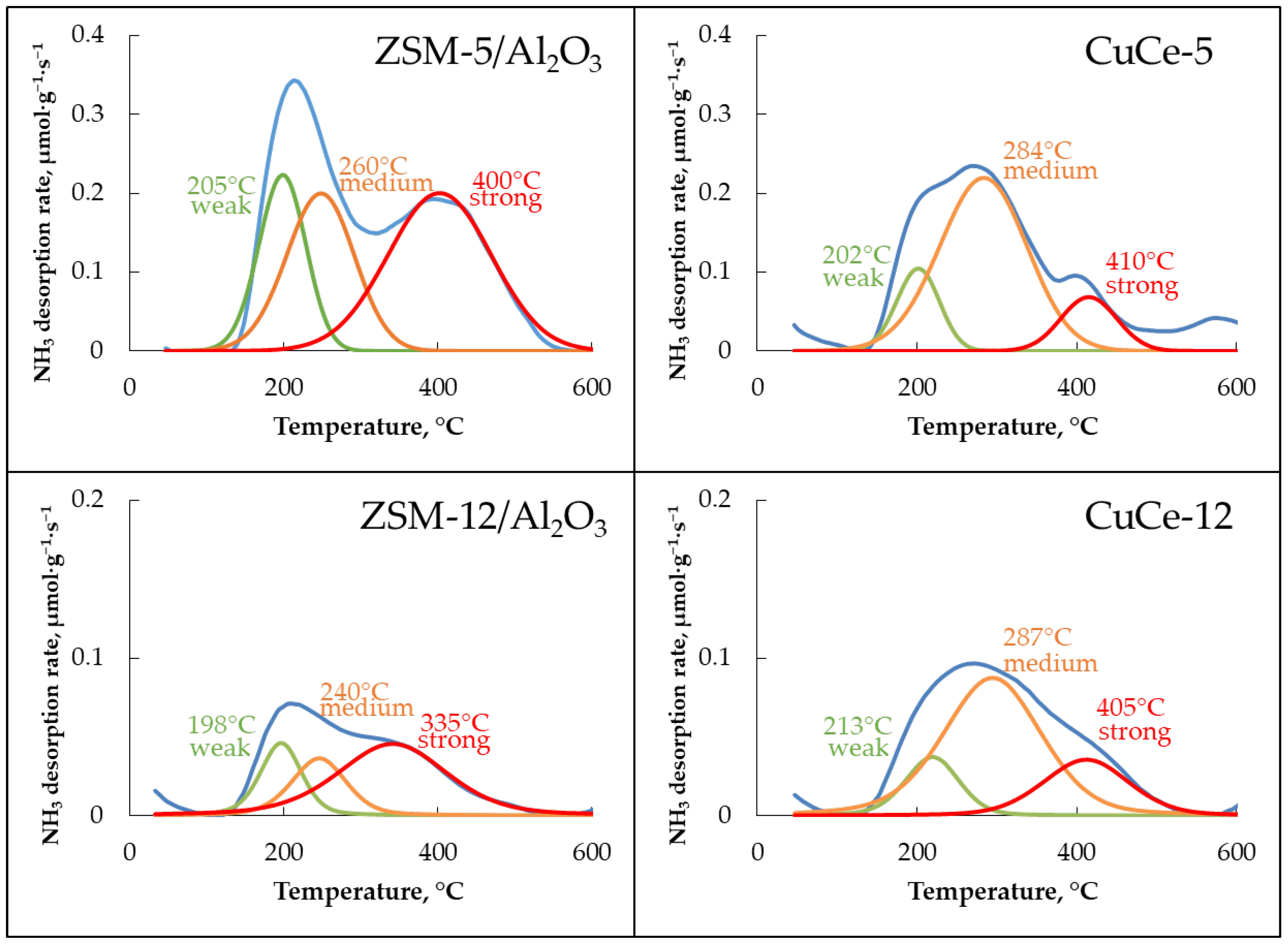
| Sample | Acid Site Concentration, μmol/g | |||
|---|---|---|---|---|
| Weak Sites ~200 °C | Medium Sites ~250 °C | Strong Sites ~400 °C | Total | |
| ZSM-5/Al2O3 | 118 | 159 | 254 | 531 |
| CuCe-5 | 49 | 223 | 45 | 317 |
| ZSM-12/Al2O3 | 23 | 25 | 65 | 113 |
| CuCe-12 | 24 | 106 | 38 | 168 |
| Catalyst | Phase | Crystallite Size, nm |
|---|---|---|
| CuCe-5 | CeO2 | 4.4 ± 0.5 |
| CuO | n/d * | |
| CuCe-12 | CeO2 | 4.6 ± 0.4 |
| CuO | 18.3 ± 0.5 |
| Catalyst | Input Power, W | Gas Flow, mL/min | η (Total), mmol·kJ−1 | X (CO2), % | X (CH4), % | Oxygenates Distribution | Source |
|---|---|---|---|---|---|---|---|
| Cu/Al2O3 | 10 | 40 | n/d * | 7 | 16 | acetic acid, methanol, ethanol, formic acid | [21] |
| Cu/Al(OH)3 | 12 | 40 | n/d | 6 | 17 | R–OH | [29] |
| Cu/Mg(OH)2 | 9 | 19 | R–OH | ||||
| Cu/SiO2 | 7 | 20 | R–OH, R–COOH | ||||
| Cu/HZSM-5 | 9 | 19 | R–OH, R–COOH | ||||
| Cu/TiO2 | 4 | 14 | R–OH, R–COOH | ||||
| Cu/CeO2 | 5 | 40 | n/d | 1 | 13 | methanol, ethanol, Pr-OH, Bu-OH, acetic acid, acetone Cu/CeO2—lowest oxygenates selectivity Cu/Al(OH)3—highest oxygenates selectivity | [38] |
| Cu/TiO2 | 4 | 5 | |||||
| Cu/γ-Al2O3 | 2.5 | 11 | |||||
| Cu/Al(OH)3 | 7 | 16 | |||||
| Cu/Al2O3 | 45 | 50 | 0.18 | 16 | 32 | methanol, ethanol, DME, formic acid | [57] |
| Cu/γ-Al2O3 | 7.5 | 50 | 0.56 | 8 | 15 | n/d | [58] |
| CuCe-5 | 8.7 | 47 | 0.65 | 12 | 20 | methanol, acetone | This work |
| CuCe-12 | 0.8 | 11 | 30 | ||||
| CuO/CeAl | 2.2 | 30 | 1.4 | 13.5 | n/a ** | n/a | [59] |
| CuO/Al2O3 | 1.6 | 15.7 |
Disclaimer/Publisher’s Note: The statements, opinions and data contained in all publications are solely those of the individual author(s) and contributor(s) and not of MDPI and/or the editor(s). MDPI and/or the editor(s) disclaim responsibility for any injury to people or property resulting from any ideas, methods, instructions or products referred to in the content. |
© 2023 by the authors. Licensee MDPI, Basel, Switzerland. This article is an open access article distributed under the terms and conditions of the Creative Commons Attribution (CC BY) license (https://creativecommons.org/licenses/by/4.0/).
Share and Cite
Golubev, O.V.; Tsaplin, D.E.; Maximov, A.L. Greenhouse Gas Conversion into Hydrocarbons and Oxygenates Using Low Temperature Barrier Discharge Plasma Combined with Zeolite Catalysts. Gases 2023, 3, 165-180. https://doi.org/10.3390/gases3040012
Golubev OV, Tsaplin DE, Maximov AL. Greenhouse Gas Conversion into Hydrocarbons and Oxygenates Using Low Temperature Barrier Discharge Plasma Combined with Zeolite Catalysts. Gases. 2023; 3(4):165-180. https://doi.org/10.3390/gases3040012
Chicago/Turabian StyleGolubev, Oleg V., Dmitry E. Tsaplin, and Anton L. Maximov. 2023. "Greenhouse Gas Conversion into Hydrocarbons and Oxygenates Using Low Temperature Barrier Discharge Plasma Combined with Zeolite Catalysts" Gases 3, no. 4: 165-180. https://doi.org/10.3390/gases3040012