Article

Influence of Hydrogen on the Performance and Emissions Characteristics of a Spark Ignition Ammonia Direct Injection Engine

1
Department of Mobility Power Research, Eco-Friendly Energy Conversion Research Division, Korea Institute of Machinery and Materials, 156 Gajeongbuk-ro, Yuseong-gu, Daejeon 34103, Republic of Korea
2
Department of Mechanical System Engineering, Jeonbuk National University, Jeonju 54896, Republic of Korea
*
Author to whom correspondence should be addressed.
Gases 2023, 3(4), 144-157; https://doi.org/10.3390/gases3040010
Submission received: 7 August 2023 / Revised: 25 September 2023 / Accepted: 10 October 2023 / Published: 16 October 2023
(This article belongs to the Special Issue Gas Emissions from Combustion Sources)

Abstract

:
Because ammonia is easier to store and transport over long distances than hydrogen, it is a promising research direction as a potential carrier for hydrogen. However, its low ignition and combustion rates pose challenges for running conventional ignition engines solely on ammonia fuel over the entire operational range. In this study, we attempted to identify a stable engine combustion zone using a high-pressure direct injection of ammonia fuel into a 2.5 L spark ignition engine and examined the potential for extending the operational range by adding hydrogen. As it is difficult to secure combustion stability in a low-temperature atmosphere, the experiment was conducted in a sufficiently-warmed atmosphere (90 ± 2.5 °C), and the combustion, emission, and efficiency results under each operating condition were experimentally compared. At 1500 rpm, the addition of 10% hydrogen resulted in a notable 20.26% surge in the maximum torque, reaching 263.5 Nm, in contrast with the case where only ammonia fuel was used. Furthermore, combustion stability was ensured at a torque of 140 Nm by reducing the fuel and air flow rates.

1. Introduction

Transportation accounts for 25% of greenhouse gas (GHG) emissions, and approximately 70% of these are from land transportation. Research efforts to curb global warming caused by vehicles are increasingly vital to environmental sustainability. Manufacturers are simultaneously distributing electrified and fuel-cell vehicles and attempting to replace existing internal combustion engines with developing highly fuel-efficient vehicles with the goal of reducing carbon dioxide by improving vehicle fuel efficiency. However, it is imperative to construct supporting infrastructure, such as a robust charging system for electrified vehicles. To reduce greenhouse gas emissions, it is necessary to fundamentally improve the electricity production system to establish an eco-friendly source of the electric energy required by electrified vehicles. Given the substantial time required for conducting a comprehensive life cycle environmental impact assessment and making improvements to electricity production systems, achieving a rapid reduction in global warming over a short period of time through the establishment of eco-friendly transportation poses significant challenges. Consequently, there is a growing focus on research aimed at reducing greenhouse gas emissions, particularly carbon dioxide, by utilizing carbon-free fuels like hydrogen or ammonia in conventional internal combustion engines.
However, utilizing ammonia in combustion poses a number of challenges [1]. The first is the requirement for a high minimum ignition energy (MIE). Hydrogen can be ignited at a stoichiometric air–fuel ratio with an MIE of 0.02 mJ, whereas ammonia requires an MIE of 8 mJ for ignition [2]. This can be a problem for the development of the initial flame. The second problem is slow laminar flame speed. In terms of theoretical air–fuel ratio, conventional hydrocarbon fuels, such as gasoline, have flame propagation speeds of approximately 0.5 m/s, while hydrogen requires about 2.3 m/s. By contrast, ammonia’s flame propagation speed is much slower, ranging from 0.05 to 0.1 m/s, posing problems in the flame propagation process during combustion [3]. Finally, ammonia fuel contains nitrogen. During high-temperature combustion in air, nitrogen oxides (NOx) are inevitably generated by nitrogen reactions in a ratio proportional to the oxygen concentration, nitrogen concentration, and temperature during combustion [4]. Owing to the large amount of nitrogen in the fuel, the generation of NOx is unavoidable, including both thermal NOx due to the reaction of nitrogen in the air and fuel NOx stemming from the fuel itself.
At present, ammonia is attracting increasing attention for its potential in the storage and transportation of hydrogen due to its ease of storage and long-distance transport; however, historically, there have been numerous endeavors to use ammonia as a fuel for engines. In 1933, Norsk Hydro produced the first truck, a small locomotive vehicle, using ammonia and hydrogen as the fuel source [5]. Since then, many automobile manufacturers have attempted to produce ammonia-powered vehicles, although, due to the low ignitability of ammonia fuel, other additive fuels were generally necessary [6,7]. In the 1960s, following a reduction in fuel stockpiles that began during World War II, research on ammonia as an alternative fuel increased. In particular, the US Department of Defense invested significantly in solving the fuel problem, and Grimes conducted research on the development of an ammonia compression-ignition engine [8]. Cooperative fuel research engine tests showed that ammonia fuel could be compressed and ignited only in a high compression ratio engine, specifically with a compression ratio of 35 [9,10]. Starkman et al. reported that combustion using pure ammonia fuel was possible even in an engine with a slightly lower compression ratio, such as a spark ignition engine with a compression ratio of 19, which matches the compression ratio of a conventional compression-ignition engine [11,12]. Despite numerous studies, the advancement of efficient ammonia engines has been hindered by challenges related to the durability of the ammonia fuel system and complexities of the intake system.
In the 2000s, Iowa State University published a case study on a compression ignition chamber engine in which a mixed combustion system of ammonia-diesel or ammonia-dimethyl ether fuel was applied; the optimal ammonia mixing ratio in this study was reported to be 60% [13,14]. When the ammonia content was below 60%, there was a reduction in NOx as the flame temperature decreased compared to the scenario in which only pure diesel fuel was used. In other research, the University of Michigan presented the case of a vehicle traveling from Detroit to San Francisco using an ammonia and gasoline hybrid engine, and the Korea Institute of Energy Research proved that stable engine operation is possible in small gasoline engines with an ammonia mixture ratio of 70% [15,16].
In recent years, liquid petroleum gas (LPG) supply systems have been modified to introduce ammonia via port fuel injection systems [17], and low-viscosity fuels, such as ammonia, methanol, and LPG, have gained considerable attention for their potential to reduce GHG emissions in marine engines [18,19]. In spark ignition ammonia engines, the addition of methane or hydrogen is frequently studied with the aim of enhancing the burn rate of ammonia [3,20]. The addition of hydrogen has been shown to extend the operational region of the ammonia engine in terms of load and speed, although the increase in wall heat loss and the possibility of backfire limits the concentration of hydrogen that can be introduced. Dimitriou [21] reported that changing the spark plug material could avoid the backfire phenomenon, and the use of multiple spark plugs has been shown to reduce the combustion duration and improve the power output of ammonia engines [22].
Nonetheless, despite several studies on the use of ammonia as a fuel, operating existing ignition engines solely on ammonia fuel faces several limitations due to its low ignition quality and combustion speed [23,24]. Most studies are limited to preliminary tests and the visualization of single-cylinder engines. Port injection can improve the initial flame speed by accelerating the combustion rate through premixed combustion; however, compared with direct injection, the volumetric efficiency is lower and the heat loss is significant. Additionally, these approaches are unsuitable for high-load operational ranges. Therefore, in this study, we attempted to identify the operational range in which stable combustion is feasible by directly injecting high-pressure ammonia fuel into an ignition engine borrowed from an existing LPG fuel supply system. Moreover, we investigated the potential for expanding the operational range by introducing a small amount of hydrogen.

2. Materials and Methods

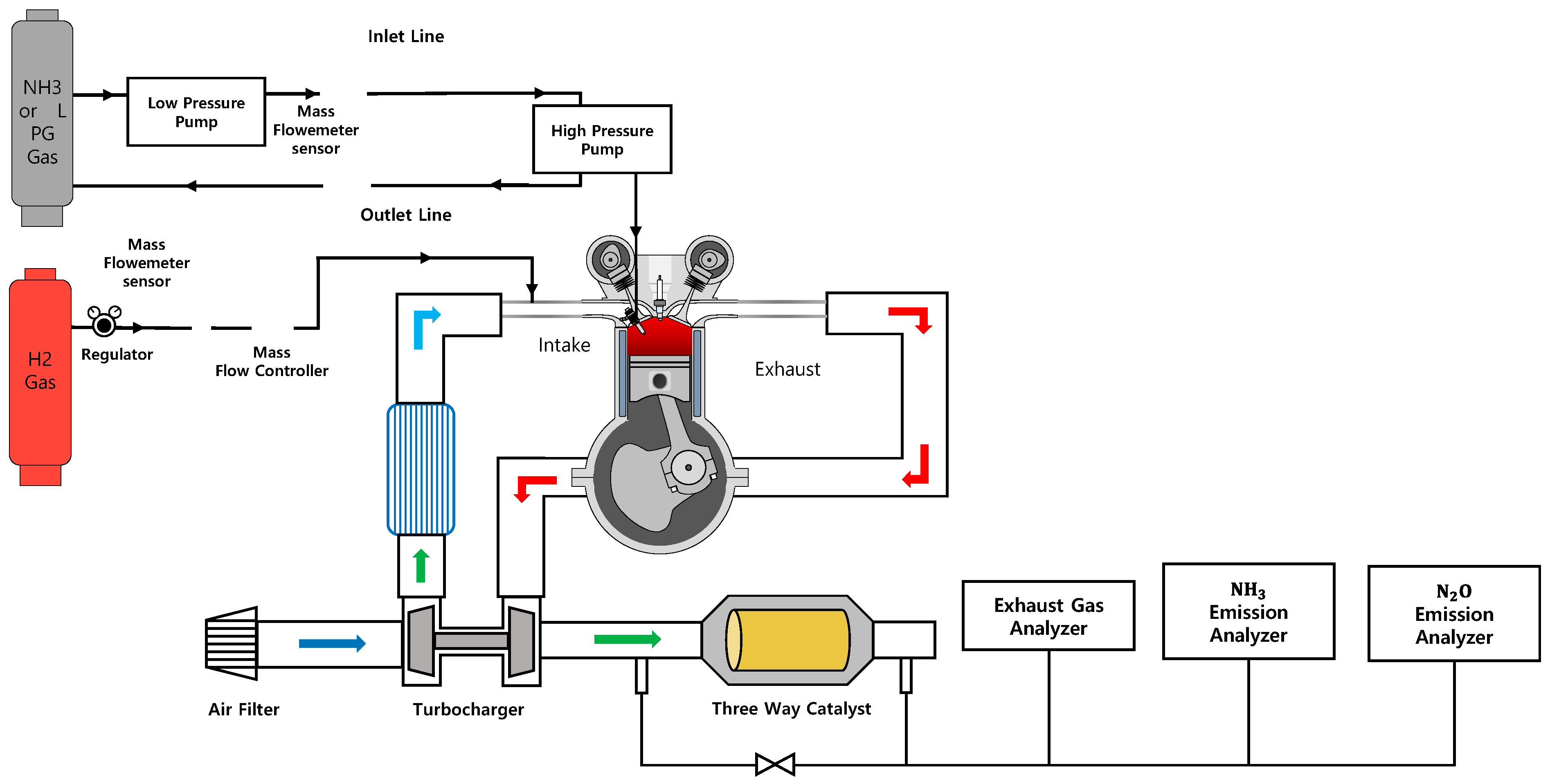
2.1. Experimental Apparatus

Table 1 shows the specifications of the passenger LPG engine used to investigate the effect of changes in driving strategy on performance and efficiency, and the maximum output of an ammonia-fueled engine using a direct-injection fuel supply system. For the 2.5 L supercharged LPG engine, a direct-injection fuel injector capable of handling fuel injection pressures of up to 15 MPa was used. However, to supply the ammonia fuel, an injector with a changed O-ring and orifice material was installed in place of the original fuel injector. Ammonia is highly corrosive to copper, brass, and zinc alloys, including aluminum brass, forming cracks or green ammonia-corrosive compounds on the surfaces of these materials. It is advisable to opt for more robust rubber materials than the commonly employed nitrile butadiene rubber (NBR), as this exhibits low resistance to ammonia and is prone to deformation. Using an existing LPG engine as a foundation, modifications were made to include a piston with a compression ratio of 10.5 and several components for high-pressure ammonia supply and control, as shown in the schematic diagram in Figure 1. As pure ammonia was used, it was essential to ensure that the ammonia discharged from the low-pressure liquid gas container was supplied in a liquid state, allowing it to be sufficiently pressurized by a high-pressure fuel pump attached to the engine and supplied to the fuel injector.
The supplementary hydrogen was stored in a high-pressure hydrogen gas tank with a pressure rating of 12 MPa and fed into the laboratory through a hydrogen fuel line connected to the engine. A regulator was employed to reduce the pressure, enabling the hydrogen to be supplied through the engine’s intake manifold at a pressure of 0.8 MPa. The flow rate of the supplied hydrogen was controlled using a thermal mass flow controller (M3400V, Linetech, Daejeon, Republic of Korea) and measured using a Coriolis mass flowmeter (CMFS010M, Micro-Motion, City of St. Louis, MO, USA).
Ammonia fuel delivery was meticulously managed through precise control of the fuel injection duration by the engine control unit. This meticulous control allowed for the regulation of the air–fuel ratio, facilitating steady-state operation. A Coriolis mass flowmeter (CMFS010P, Micro-Motion) was used to measure the flow rate. By monitoring the engine control state, data such as the excess air ratio and ignition timing and the combustion control variables that directly affect the engine performance were acquired. The engine speed and load were controlled using an alternating current (AC) dynamometer (INDY S33-2/0700-1BS-1, AVL, Graz, Austria). The combustion performance was determined by measuring the combustion pressure using a spark plug-type pressure sensor (6113CF, Kistler, Winterthur, Swiss) and a combustion analyzer (DEWE211, DEWETRON Co., Grambach, Austria). In addition, temperature and pressure sensors were installed to measure the temperature and pressure of key parts of the engine. The air flow rate was measured using a flowmeter (FSA 100, AVL, Graz, Austria), and the engine air–fuel ratio was measured in front of the catalyst using a wide-band lambda meter (LA4, ETAS Co., Stuttgart, Germany). NOx and unburned ammonia emissions, which can be released without combustion among the exhausted gases produced by the engine, were measured using an exhaust gas analyzer (SESAM FTIR, AVL, Graz, Austria).

2.2. Experimental Procedure

In this study, the initial investigation focused on using ammonia as the sole fuel to evaluate engine operability and assess the potential expansion of the operating range without the addition of hydrogen. After several rounds of trial and error with ammonia as the sole fuel, stable operation was found to be possible only under operating conditions of 1500 rpm and 180 Nm or higher, as shown in Figure 2. Under all operating conditions, the excess air ratio was maintained at 1.1, as the combustion stability deteriorated rapidly in leaner or richer mixtures. This corresponds to the excess air ratio reported by Ichimura et al. in the stabilization region with the widest range of ammonia/air flames under turbulent conditions [25]. At engine speeds exceeding 1500 rpm, stable combustion was impossible due to an insufficient chemical reaction time to maintain the flame front. However, when hydrogen was added under the same conditions, the experimental results showed that both the resistance to turbulence and the number of engine revolutions increased, enabling stable operation.
Because ammonia fuel has a high autoignition temperature of 650 °C and the latent heat of vaporization of liquid ammonia is as high as 327 kcal/kg, the ignition source of the spark plug used in this experiment was insufficient to maintain stable combustion. This inadequacy was attributed to the cooling of the mixture by latent heat, especially under low-load or low-speed operating conditions of 1500 rpm or less, when the density of the mixture relative to the combustion chamber displacement is low. One important measure of cyclic variability derived from the pressure data is the coefficient of variation in the indicated mean effective pressure (IMEP) [4]. The coefficient of variation of the indicated mean effective pressure (COVIMEP) is the standard deviation of the IMEP divided by the mean IMEP and is usually expressed as a percentage:
C O V I M E P = σ I M E P I M E P × 100 ,
where σIMEP is the standard deviation in IMEP.
As a result, the COVIMEP value representing the combustion stability was measured to be 5% or higher at a torque of 181.5 Nm (the lowest torque shown in Figure 2), and misfiring was confirmed during the actual experiment.
Working from the established premise that stable combustion is possible at an engine speed of 1500 rpm (Figure 2), we assessed the potential for increased output and rotational speed by adding hydrogen. We explored the potential for expanding the operational range by utilizing the low ignition energy of hydrogen and its capability to increase combustion speed, even within the low-load operational range. Considering the practical challenges of supplying hydrogen fuel in a passenger vehicle, the hydrogen-to-ammonia energy ratio was set to 10% when adding the hydrogen to the supplied ammonia fuel. When the engine speed increased, the hydrogen supply flow rate was adjusted to assess the operable energy ratio. The energy ratio of hydrogen is determined by the ratio of the heating value of hydrogen to the total heating value of the combined input of ammonia and hydrogen during engine operation. This can be expressed as follows:
E n e r g y   f r a c t i o n   o f   H 2 = L H V H 2 L H V H 2 + L H V L H V N H 3 ,
where L H V H 2 and L H V N H 3 are the lower heating values of hydrogen and ammonia, respectively.
Ignition timing optimization was performed under each operating condition to achieve the minimum advance for the best torque (MBT) ignition timing condition. As it is difficult to achieve combustion stability even when the engine operating conditions are constant and the engine coolant and engine oil temperatures are low, the experiment was conducted in a sufficiently warmed-up state (90 ± 2.5 °C).

3. Results and Discussion

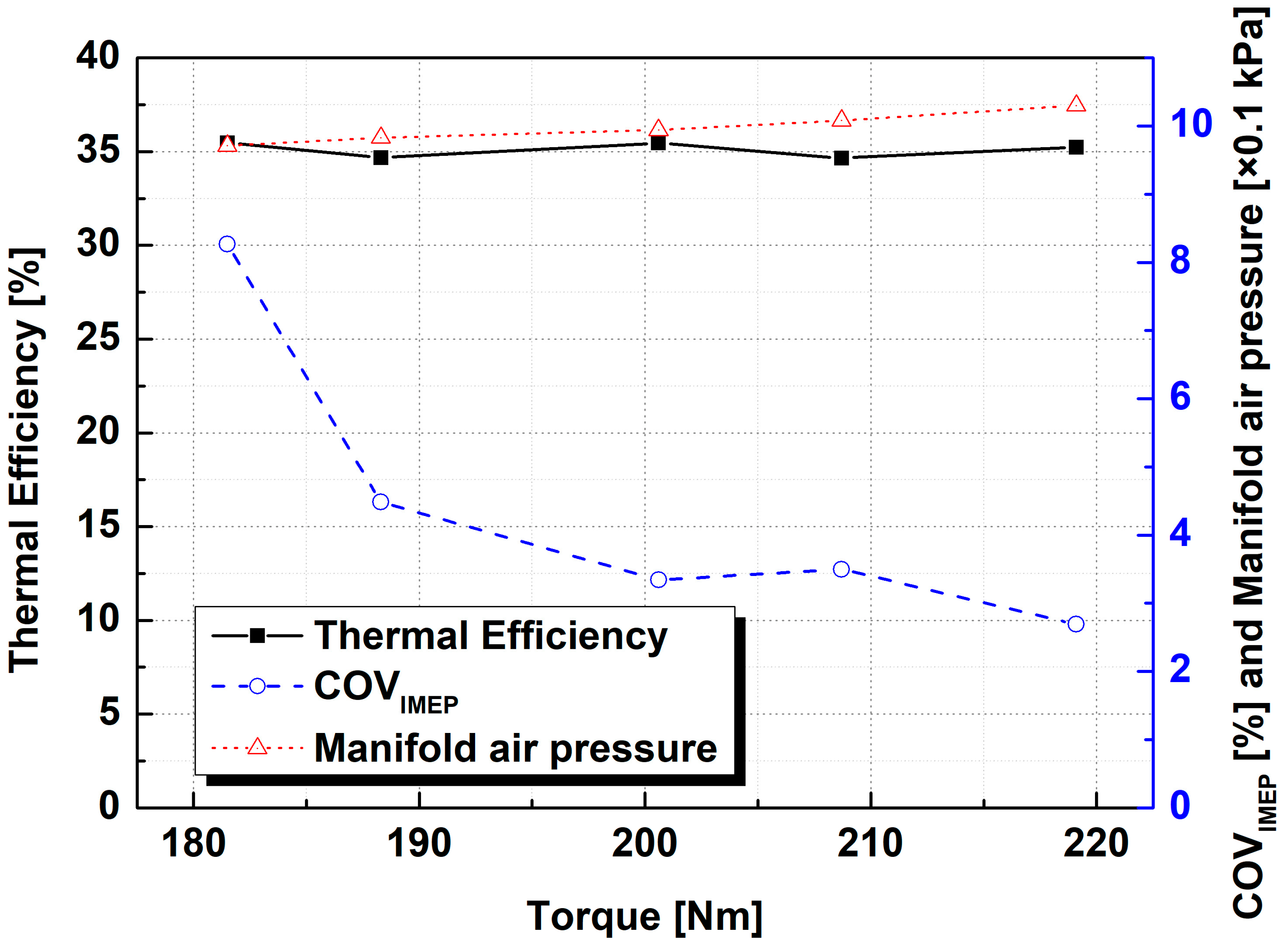
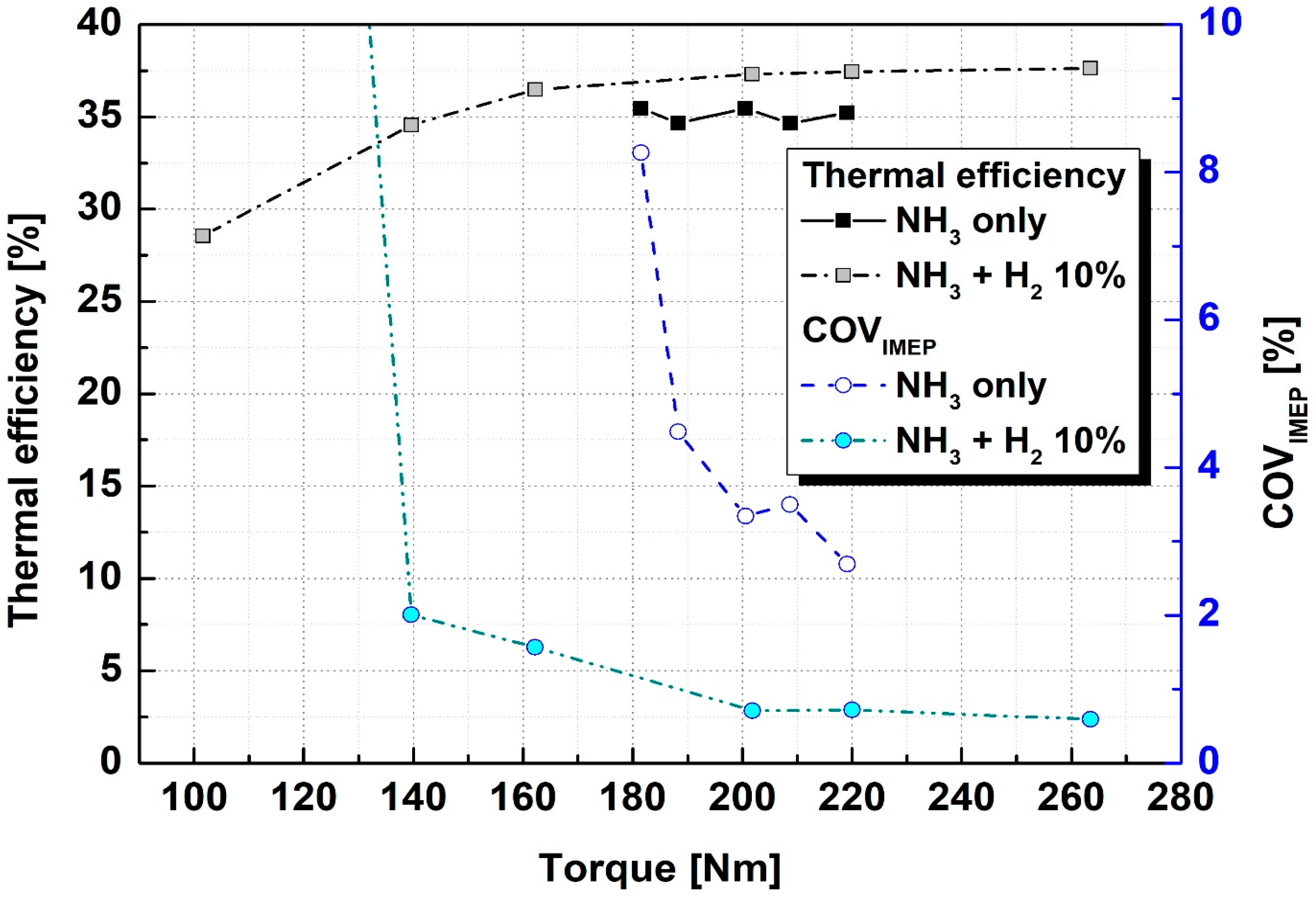
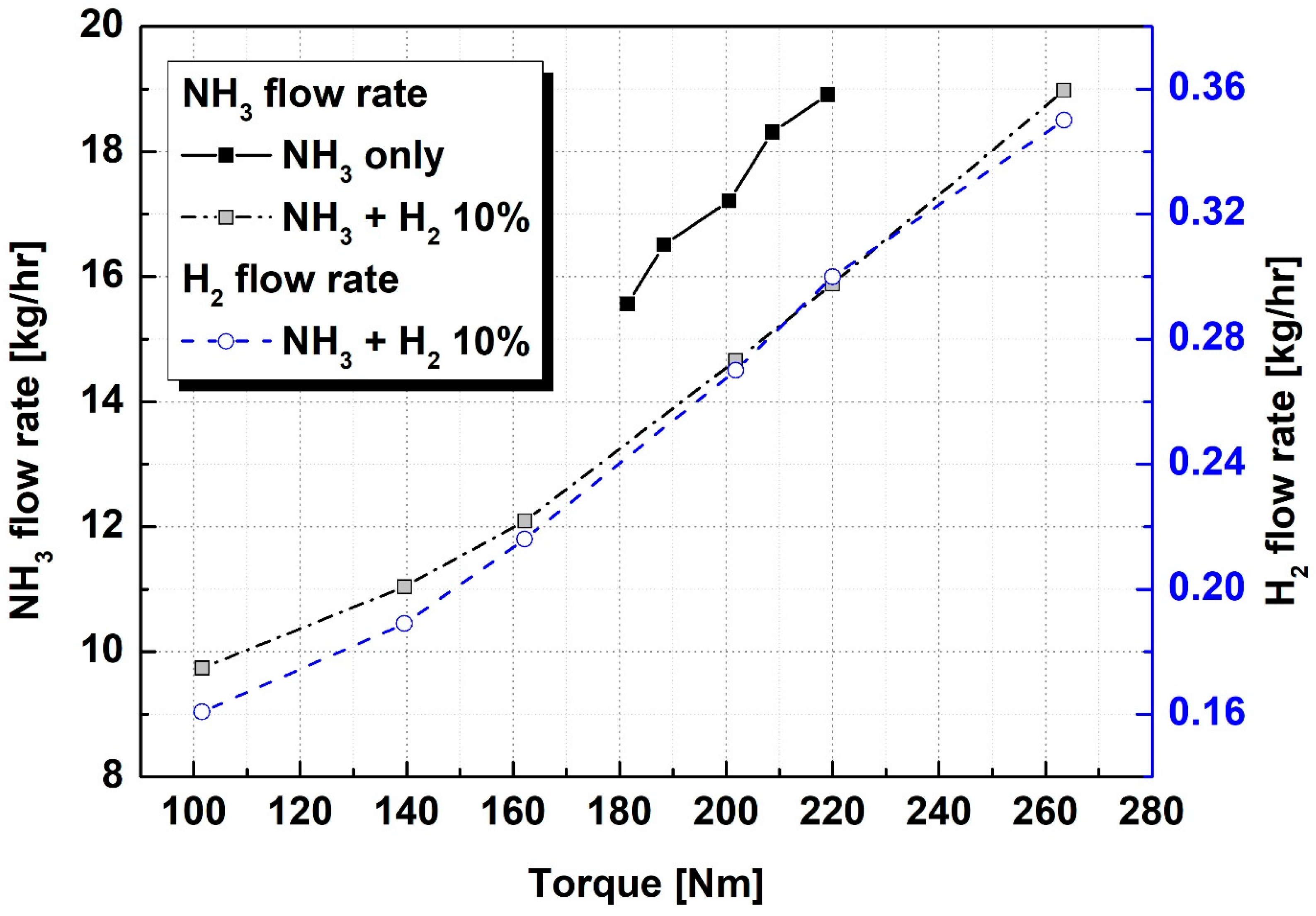
3.1. Load Extension with Hydrogen Addition

First, the load expansion results for a hydrogen mixture with an energy ratio of 10% and an engine speed of 1500 rpm were examined. As can be seen in Figure 3, following the addition of hydrogen, the maximum torque increased by 20.26% to 263.5 Nm compared to the case of using ammonia as the sole fuel. The maximum torque was limited by the flow rate of ammonia, which was supplied by a high-pressure fuel pump under each operating condition. Considering the supplied fuel flow rates, the ammonia supply flow rate remains consistent at 19 kg/h, in contrast to the case where hydrogen is added (Figure 4). However, the maximum torque value increases significantly, owing to the energy increase and efficiency improvement by hydrogen.
The brake thermal efficiency was calculated from the cylinder pressures [4] as follows:
η t h , b r a k e = b p m ˙ f u e l L H V f u e l ,
where bp is the measured brake power in kW, and LHVfuel is the lower heating value of the fuel.
When operating using ammonia as the sole fuel, COVIMEP remains below 5%, except for under the lowest torque condition. This indicates a combustion stability of approximately 4%. However, when hydrogen was added, the combustion stability improved significantly, reducing COVIMEP to less than 2%. This improved combustion stability resulted in an increase in thermal efficiency of approximately 2% under similar load conditions. Combustion stability was maintained under a torque of 140 Nm by reducing the fuel and air flow rates while maintaining an excess air ratio of 1.1. However, under lower torque conditions, misfiring occurred repeatedly, making its stable operation impossible, and consequently reducing efficiency.
Figure 5 shows the change in the optimum ignition timing and exhaust gas temperature under the same operating conditions as shown in Figure 3. As shown in Figure 5, when only ammonia is used as fuel, a marginal retardation in ignition timing is observed with increasing torque, becoming noticeably advanced by a crank angle (CAD) of approximately 45 degrees before the top dead center (BTDC). However, when hydrogen was added, the combustion speed increased and the optimum ignition timing was delayed by approximately 15 CAD BTDC under similar torque conditions. As reported by Lhuillier et al. [3], when approximately 10% hydrogen is mixed with ammonia fuel, the laminar flame propagation speed increases slightly to 9.5 cm/s. This can be attributed to the rapid increase in the turbulent flame propagation speed corresponding to the increase in the combustion rate and turbulence intensity, owing to thermal diffusion instability. The enhanced combustion rate following the introduction of hydrogen improves combustion stability and thermal efficiency. Owing to the relatively rapid combustion under high-load conditions where the overall energy of the ammonia and hydrogen mixture is high, the optimal ignition timing was retarded below 30 CAD BTDC. Under low-load conditions, the optimal ignition timing was also retarded but in a manner similar to that found when using ammonia as the sole fuel. As discussed above, because the relatively slow combustion speed of the ammonia–air mixture (attaining a maximum of 7 cm/s) compared to that of other hydrocarbon-based fuels, practical engine operation necessitates improving the ignition timing to compensate for the low combustion speed.
Using ammonia as the sole fuel, the optimal ignition timing was retarded and the energy of the mixture increased with increasing torque; thus, the exhaust gas temperature increased even though the thermal efficiencies were similar. When hydrogen was added, the thermal efficiency increased slightly as the torque increased. However, retardation of the ignition timing was the dominant effect, leading to an increase in the exhaust gas temperature. At a torque of 100 Nm, a low-load condition in which combustion stability is not secured, the difference in ignition timing compared to that achieved at a torque of 140 Nm was not large, but the exhaust gas temperature decreased rapidly. Because the energy of the fuel does not affect the temperature increase of the exhaust gas under low-efficiency conditions, a large amount of unburned fuel is expected to be present in the exhaust gas; this can be verified through examination of the subsequent exhaust gas results.
The changes in the intake manifold pressure and air flow rate under the same operating conditions are shown in Figure 6. Under constant torque, the intake manifold pressure either remained relatively consistent regardless of hydrogen addition or was slightly higher, owing to low efficiency; however, the intake air flow rate decreased when hydrogen was added. Although the stoichiometric air–fuel ratio of ammonia is 6.04, which is very low compared to that of hydrogen (34), the volume of the mixture for a certain level of torque output is similar. However, as shown in Figure 4, when hydrogen was added, the required flow rate of intake air decreased because the decrease in the supply flow rate of ammonia was large and the increase in that of hydrogen (which has high energy per mass) was relatively small. The addition of hydrogen leads to a reduction in the required air flow rate for power increase, which is judged to be advantageous in the operation of ammonia and hydrogen engines. These engines typically exhibit low exhaust energy because of the low molecular weight of the fuel.
Figure 7 shows the results of the ignition delay (CAD from ignition timing to 10% of the mass fraction burned (MFB10)) and combustion duration (CAD from MFB10 to 90% of the mass fraction burned (MFB90)), used to evaluate the ignition performance, and combustion speed, according to the change in fuel. Because the ignition time when utilizing ammonia as the sole fuel was approximately 45 CAD, the timing of MFB10 (considered ignition) can be seen from the ignition delay of approximately 40 CAD to be close to the TDC. Considering that the combustion period is about 45 CAD, the ignition delay occupies close to half of the total combustion period from the ignition time to MFB90. When only ammonia was used, the ignition delay and combustion duration had little effect on the load change. However, when hydrogen was added, the ignition delay and combustion duration decreased as the load increased. At a torque of 220 Nm, the ignition delay decreased from 38.33 CAD to 21.5 CAD, and the combustion duration decreased from 43.38 CAD to 26.84 CAD, a reduction in both the time to ignition and burning period. The improvement in combustion stability and the reduction in the overall combustion duration due to the addition of hydrogen led to a consequent improvement in efficiency. The decrease in combustion duration with the increase in load can be considered to be the cause of the high efficiency achieved under high-load conditions.
The changes in the NOx and unburned ammonia emissions with the addition of hydrogen are shown in Figure 8. Under an excess air ratio of 1.1, which generally results in high NOx emissions, the emissions were lower than expected, regardless of hydrogen addition. When only ammonia was used as fuel, the difference in ignition timing was not large, and the NOx emissions only increased slightly (to 2000 ppm) as the load increased. However, when hydrogen was added, the NOx emissions increased as the torque increased, up to a load of 200 Nm, and then decreased again at higher torques. As the load increased, the combustion duration decreased and the ignition timing was retarded. However, because of the efficiency improvement and the fact that the amount of fuel input increased as the torque increased, up to a load of 200 Nm, we believe that the increase in NOx emissions is correlated with rising combustion temperatures.
In the case of unburned NH3, the emissions increased significantly owing to intermittent misfiring under conditions of low combustion stability. As the amount of ammonia supplied increased with the load, the amount of ammonia discharged without participating in the combustion also increased. The NH3 emission, according to the increase in load, increased significantly when only ammonia was used as fuel compared to when hydrogen was added. The addition of hydrogen significantly reduced the emission level of unburned NH3, an effect which continued to increase as the torque increased. It is believed that the increased amount of fuel introduced into the cylinder forms a premixed mixture, and a portion of the lean mixture near the cylinder wall remains unburned and is discharged from the engine. The lowest unburned NH3 emission was 4856 ppm at a torque of 160 Nm; however, because this level is very high compared to the unburned hydrocarbon emission level of general hydrocarbon-based fuel, a post-treatment system for reducing it is required in the future.

3.2. Speed Extension with Hydrogen Addition

As mentioned in Section 2, although stable operation of an ammonia engine is impossible under engine speed conditions higher than 1500 rpm because of the slow combustion rate of ammonia, based on the above experimental results, it is indeed possible to expand the operating range by adding hydrogen. Because the combustion speed is based on the physical properties of the fuel and is constant, regardless of the engine speed, the amount of hydrogen added must be increased to increase the combustion speed in proportion to the engine speed. Considering the results showing the ammonia and hydrogen fuel flow rates and the ratio of hydrogen fuel with respect to variations in engine speed in Figure 9, up to 2000 rpm, stable operation was possible with only 10% hydrogen addition; however, at higher engine speeds combustion was stabilized only when the hydrogen ratio increased. At 3000 rpm, the flow rate of hydrogen to be supplied was 1 kg/h, and a high hydrogen energy rate of 17% or more was required.
However, when looking at the graph in Figure 10 which shows changes in torque, thermal efficiency, and combustion stability under the same operating conditions, although a combustible operating condition was selected because it maintains a torque of over 200 Nm at 3000 rpm, the frequency of misfires was high. Therefore, the COVIMEP value representing combustion stability was very high at 25%. At an engine speed of 2500 rpm or higher, misfiring occurs even if hydrogen is added, and the torque is reduced compared to that experienced at low speed. Consequently, the thermal efficiency decreases as the engine speed increases.
Figure 11 shows the result of measuring NOx and unburned NH3 emissions according to the increase in engine speed. As the engine speed increased, the energy of the fuel supplied increased; therefore, even at 2000 rpm, under similar hydrogen addition conditions, NOx emissions increased compared to their levels at 1500 rpm. Above 2500 rpm, there was a further increase in NOx emissions, with an increase in input energy. This was due to the rising proportion of hydrogen, which facilitates a high combustion speed and adiabatic flame temperature. As it was difficult to establish stable combustion above 2500 rpm, the emission of unburned NH3 increased as COVIMEP increased, as expected.

4. Conclusions

In this study, the possibility of expanding the operating range of a 2.5 L spark ignition ammonia engine by the addition of hydrogen was examined, and the experimental combustion, exhaust, and efficiency results under various operating conditions were compared. The results are summarized as follows:
  • Stable combustion is impossible under low-load or low-speed operating conditions (where the density of the mixture relative to the displacement of the combustion chamber is low), as well under engine speed conditions higher than 1500 rpm, because of the cooling of the mixture by latent heat and the slow combustion rate of ammonia, respectively.
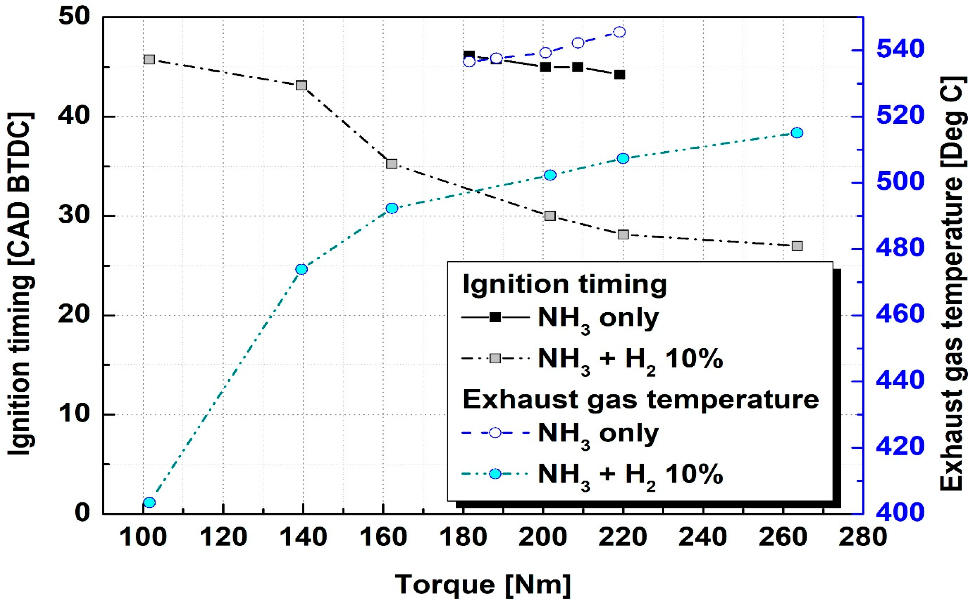
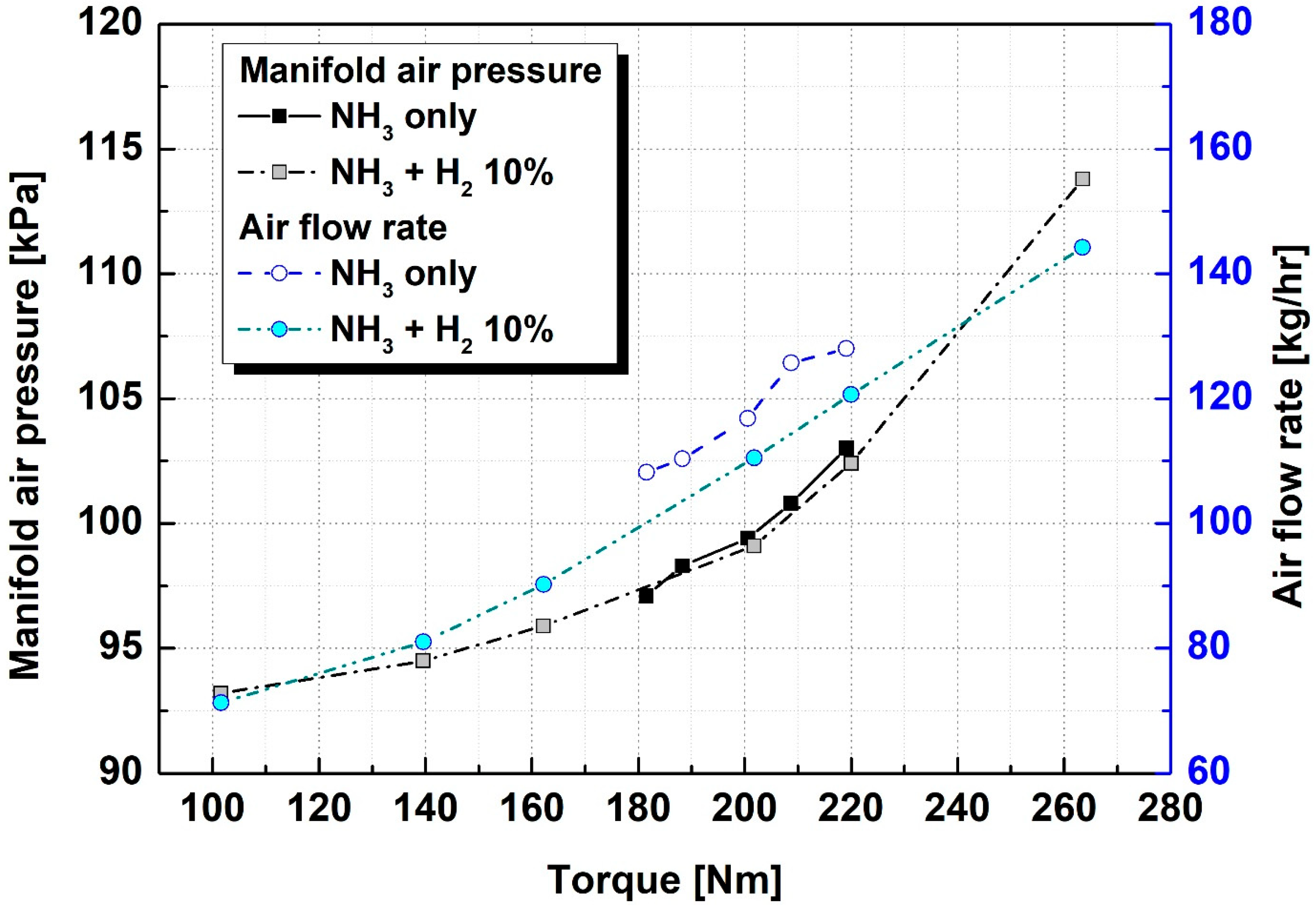
  • At 1500 rpm, with the addition of 10% hydrogen, a maximum torque of 263.5 Nm, 20.26% more than that achievable with only ammonia fuel, was attained. Moreover, by reducing the fuel and air flow rates, combustion stability was established at a torque of 140 Nm.
  • Under constant torque, the intake manifold pressure was similar, irrespective of hydrogen addition, or was slightly higher owing to low efficiency; however, the intake air flow rate decreased when hydrogen was added.
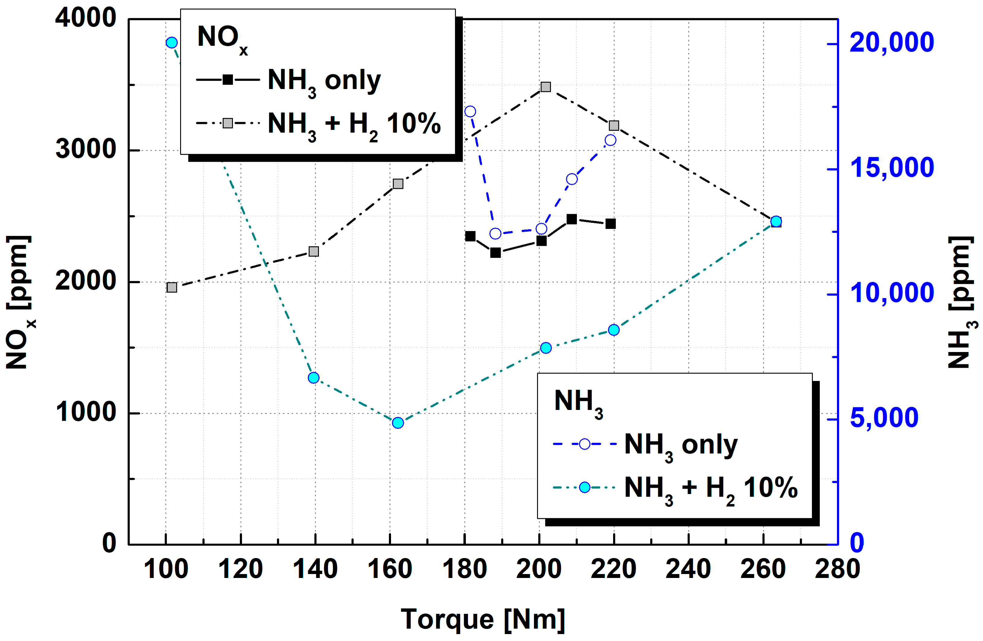
  • When only ammonia was used as the fuel, the difference in ignition timing was not large, resulting in a very minor increase of NOx to 2000 ppm as the load increased. With the addition of hydrogen, the NOx emission increased as the torque increased, up to a load of 200 Nm, and then decreased again under higher torque conditions.
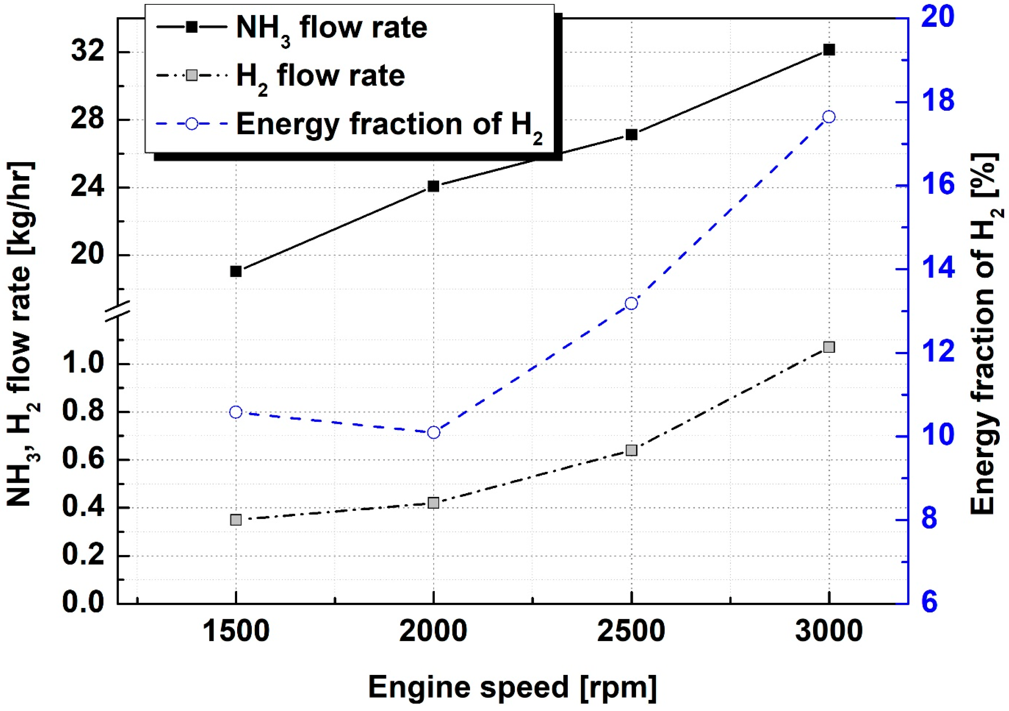
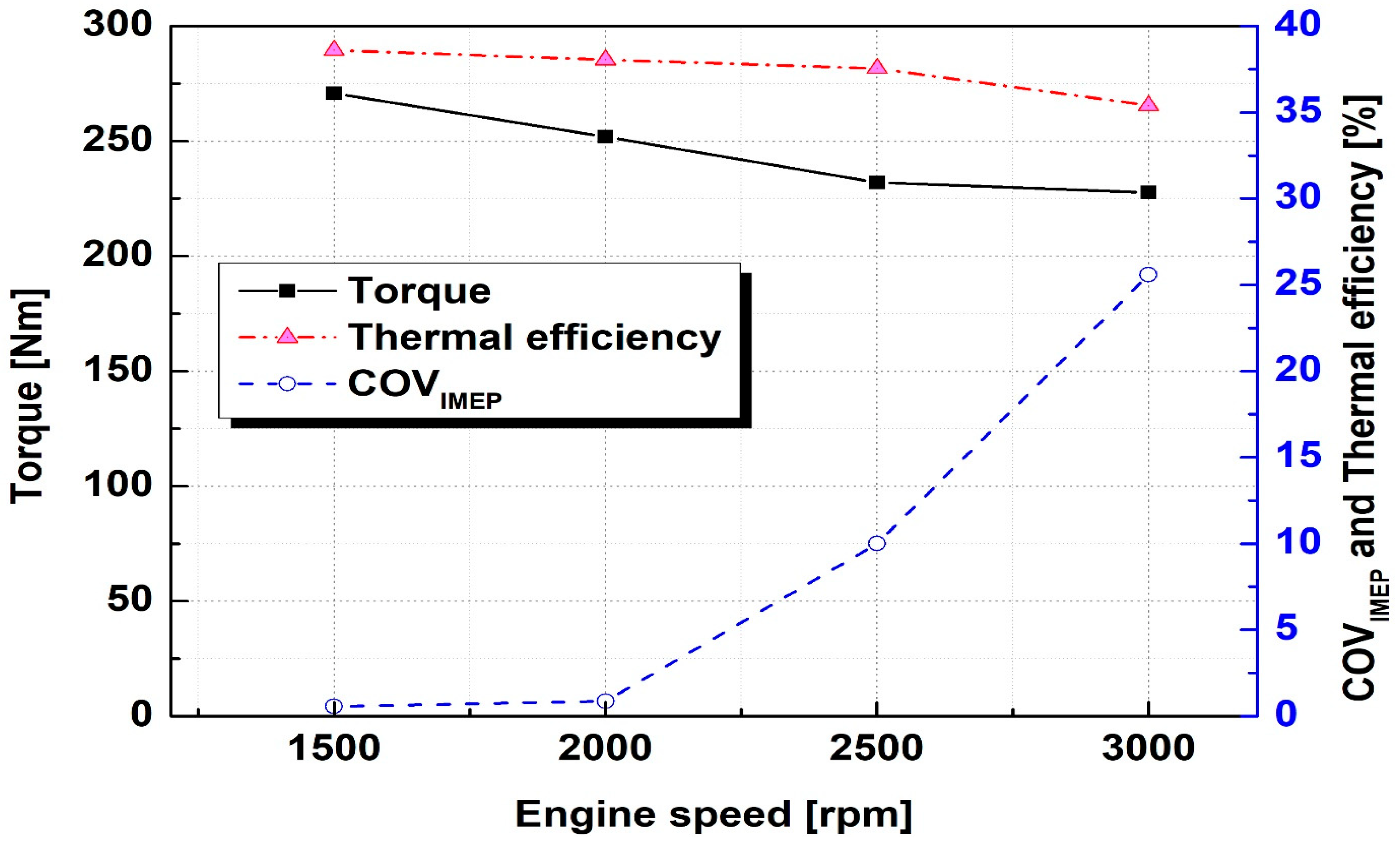
  • Up to 2000 rpm, stable operation of the ammonia engine was possible with only 10% hydrogen addition; however, combustion was stabilized at higher engine speeds only when the hydrogen ratio increased. At 3000 rpm, the flow rate of the supplied hydrogen was 1 kg/h, and a high hydrogen energy rate of 17% or more was required.

Author Contributions

Supervision, writing—Original draft preparation, C.P.; data curation, Y.J.; formal analysis, S.K.; methodology, Y.K.; project administration, Y.C. All authors have read and agreed to the published version of the manuscript.

Funding

This research was a part of two projects, one entitled “Development of 2100 PS LNG-Ammonia dual fuel engine”, funded by the Korean Ministry of Oceans and Fisheries (Project No. 1525011796), and the other entitled “Development of core parts technology for non-carbon fuel main propulsion engine”, funded by the Ministry of Trade, Industry, and Energy, Republic of Korea (Project No. 20017612).

Data Availability Statement

All data are confidential.

Conflicts of Interest

The authors declare no conflict of interest.

Nomenclature

BTDCBefore top dead center
CADCrank angle degree
COVIMEPCoefficient of variation for indicated mean effective pressure
LPGLiquid petroleum gas
MBTMinimum advance for the best torque
MFB1010% of mass fraction burned
MFB9090% of mass fraction burned
MIEMinimum ignition energy

References

  1. Kobayashi, H.; Hayakawa, A.; Somarathne, K.D.K.A.; Okafor, E.C. Science and technology of ammonia combustion. Proc. Combust. Inst. 2019, 37, 109–133. [Google Scholar] [CrossRef]
  2. Chung, Y.H.; Lee, W.-J.; Kang, J.; Yoon, S.H. Fire Safety Evaluation of High-Pressure Ammonia Storage Systems. Energies 2022, 15, 520. [Google Scholar] [CrossRef]
  3. Lhuillier, C.; Brequigny, P.; Contino, F.; Mounaïm-Rousselle, C. Experimental investigation on ammonia combustion behavior in a spark-ignition engine by means of laminar and turbulent expanding flames. Proc. Combust. Inst. 2021, 38, 5859–5868. [Google Scholar] [CrossRef]
  4. Heywood, J.B. Internal Combustion Engine Fundamentals; McGraw-Hill: New York, NY, USA, 1988. [Google Scholar]
  5. Lesmana, H.; Zhang, Z.; Li, X.; Zhu, M.; Xu, W.; Zhang, D. NH3 as a Transport Fuel in Internal Combustion Engines: A Technical Review. J. Energy Resour. Technol. 2019, 141, 070703. [Google Scholar] [CrossRef]
  6. Zakva, M. Device for Operating Internal Combustion Engines with Mixtures of Ammonia, Hydrogen, and Nitrogen Prepared from Ammonia. U.S. Patent 2,140,254, 13 December 1938. [Google Scholar]
  7. Koch, E. Ammonia–a fuel for motor buses. J. Inst. Pet. 1945, 31, 213. [Google Scholar]
  8. Grimes, P.G. Energy Depot Fuel Production and Utilization. SAE Trans. 1965, 74, 281–299, 316–326. [Google Scholar] [CrossRef]
  9. Rosenthal, A.B. Energy depot—A concept for reducing the military supply burden. SAE Trans. 1966, 74, 274–326. [Google Scholar]
  10. Gray, J.T.; Dimitroff, E.; Meckel, N.T.; Quillian, R.D. Ammonia Fuel—Engine Compatibility and Combustion. SAE Trans. 1966, 75, 785–807. [Google Scholar] [CrossRef]
  11. Starkman, E.S.; James, G.E.; Newhall, H.K. Ammonia as a Diesel Engine Fuel: Theory and Application. SAE Trans. 1967, 76, 3193–3212. [Google Scholar] [CrossRef]
  12. Garabedian, C.G.; Pearsall, T.J. Combustion of Anhydrous Ammonia in Diesel Engines. SAE Trans. 1967, 76, 3213–3221. [Google Scholar] [CrossRef]
  13. Reiter, A.J.; Kong, S.-C. Combustion and emissions characteristics of compression-ignition engine using dual ammonia-diesel fuel. Fuel 2011, 90, 87–97. [Google Scholar] [CrossRef]
  14. Gross, C.W.; Kong, S.-C. Performance characteristics of a compression-ignition engine using direct-injection ammonia–DME mixtures. Fuel 2013, 103, 1069–1079. [Google Scholar] [CrossRef]
  15. Grannell, S.M.; Assanis, D.N.; Bohac, S.V.; Gillespie, D.E. The Fuel Mix Limits and Efficiency of a Stoichiometric, Ammonia, and Gasoline Dual Fueled Spark Ignition Engine. J. Eng. Gas Turbines Power 2008, 130, 042802. [Google Scholar] [CrossRef]
  16. Jang, J.; Woo, Y.; Yoon, H.C.; Kim, J.-N.; Lee, Y.; Kim, J. Combustion characteristics of ammonia-gasoline dual-fuel system in a one liter engine. J. Korean Inst. Gas 2015, 19, 1–7. [Google Scholar] [CrossRef]
  17. Frigo, S.; Gentili, R. Analysis of the behaviour of a 4-stroke Si engine fuelled with ammonia and hydrogen. Int. J. Hydrog. Energy 2013, 38, 1607–1615. [Google Scholar] [CrossRef]
  18. Kurien, C.; Mittal, M. Review on the production and utilization of green ammonia as an alternate fuel in dual-fuel compression ignition engines. Energy Convers. Manag. 2022, 251, 114990. [Google Scholar] [CrossRef]
  19. Willmann, M.; Berger, I.; Bärow, E. Woodward L’Orange’s New Injector Generation—An Ideal Platform for the Combustion of E-Fuels in Large Engines BT—Heavy-Duty-, On- und Off-Highway-Motoren 2020; Liebl, J., Ed.; Springer Fachmedien Wiesbaden: Wiesbaden, Germany, 2021; pp. 223–240. [Google Scholar]
  20. Wang, B.; Wang, H.; Duan, B.; Yang, C.; Hu, D.; Wang, Y. Effect of ammonia/hydrogen mixture ratio on engine combustion and emission performance at different inlet temperatures. Energy 2023, 272, 127110. [Google Scholar] [CrossRef]
  21. Dimitriou, P.; Javaid, R. A review of ammonia as a compression ignition engine fuel. Int. J. Hydrog. Energy 2020, 45, 7098–7118. [Google Scholar] [CrossRef]
  22. D’Antuono, G.; Lanni, D.; Galloni, E.; Fontana, G. Comparison of the Performance and Operation Limits of an S.I. Engine Fueled with Neat Ammonia and Hydrogen-Ammonia Blends. In Proceedings of the 16th International Conference on Engines & Vehicles, Capri, Italy, 10–14 September 2023; SAE International: Warrendale, PA, USA, 2023. [Google Scholar] [CrossRef]
  23. Oh, S.; Park, C.; Oh, J.; Kim, S.; Kim, Y.; Choi, Y.; Kim, C. Combustion, emissions, and performance of natural gas–ammonia dual-fuel spark-ignited engine at full-load condition. Energy 2022, 258, 124837. [Google Scholar] [CrossRef]
  24. Won, H. Study on the Possibility of Using Pure NH3 Fuel on a Spark Ignition Engine with a High Compression Ratio. Trans. KSAE 2022, 30, 865–871. [Google Scholar] [CrossRef]
  25. Ichimura, R.; Hadi, K.; Hashimoto, N.; Hayakawa, A.; Kobayashi, H.; Fujita, O. Extinction limits of an ammonia/air flame propagating in a turbulent field. Fuel 2019, 246, 178–186. [Google Scholar] [CrossRef]
Figure 1. Schematic diagram of experimental setup.
Gases 03 00010 g001
Figure 2. Thermal efficiency, combustion stability, and intake manifold pressure for ammonia engine with various engine torques at 1500 rpm.
Gases 03 00010 g002
Figure 3. Thermal efficiency and combustion stability for hydrogen-added ammonia engine with various engine torques at 1500 rpm.
Gases 03 00010 g003
Figure 4. Ammonia and hydrogen flow rate for hydrogen-added ammonia engine with various engine torques at 1500 rpm.
Gases 03 00010 g004
Figure 5. Ignition timing and exhaust gas temperature for hydrogen-added ammonia engine with various engine torques at 1500 rpm.
Gases 03 00010 g005
Figure 6. Intake manifold air pressure and air flow rate for hydrogen-added ammonia engine with various engine torques at 1500 rpm.
Gases 03 00010 g006
Figure 7. Ignition delay and combustion duration for hydrogen-added ammonia engine with various engine torques at 1500 rpm.
Gases 03 00010 g007
Figure 8. NOx and unburned NH3 emissions for hydrogen-added ammonia engine with various engine torques at 1500 rpm.
Gases 03 00010 g008
Figure 9. Ammonia flow rate, hydrogen flow rate, and energy fraction of hydrogen for hydrogen-added ammonia engine with various engine speeds and wide open throttle.
Gases 03 00010 g009
Figure 10. Torque, combustion stability, and thermal efficiency for hydrogen-added ammonia engine with various engine speeds and wide open throttle.
Gases 03 00010 g010
Figure 11. NOx and NH3 emissions for hydrogen-added ammonia engine with various engine speeds and wide open throttle.
Gases 03 00010 g011
Table 1. Specifications of test engine.
ItemSpecification
Displacement volume [cc]2497
Number of cylinders [-]4
Compression ratio [-]10.5
Bore × Stroke [mm]88.5 × 101.5
Max. Torque [Nm]26.0 @ 3800 rpm (w/LPG)
Max. Power [kW]101 @ 3800 rpm(w/LPG)
Disclaimer/Publisher’s Note: The statements, opinions and data contained in all publications are solely those of the individual author(s) and contributor(s) and not of MDPI and/or the editor(s). MDPI and/or the editor(s) disclaim responsibility for any injury to people or property resulting from any ideas, methods, instructions or products referred to in the content.

