Article

Advancements in Designing the DEMO Driver Blanket System at the EU DEMO Pre-Conceptual Design Phase: Overview, Challenges and Opportunities

1
Karlsruhe Institute of Technology, 76344 Eggenstein-Leopoldshafen, Germany
2
ENEA C.R. Brasimone, 40032 Camugnano, Italy
3
Commissariat à l’Energie Atomique et aux Energies Alternatives, 46500 Cadarache, France
4
EUROfusion Programe Management Unit, 85748 Garching, Germany
*
Author to whom correspondence should be addressed.
J. Nucl. Eng. 2023, 4(3), 565-601; https://doi.org/10.3390/jne4030037
Submission received: 1 November 2022 / Revised: 20 June 2023 / Accepted: 21 June 2023 / Published: 3 August 2023

Abstract

:
The EU conducted the pre-conceptual design (PCD) phase of the demonstration reactor (DEMO) during 2014–2020 under the framework of the EUROfusion consortium. The current strategy of DEMO design is to bridge the breeding blanket (BB) technology gaps between ITER and a commercial fusion power plant (FPP) by playing the role of a “Component Test Facility” for the BB. Within this strategy, a so-called driver blanket, with nearly full in-vessel surface coverage, will aim at achieving high-level stakeholder requirements of tritium self-sufficiency and power extraction for net electricity production with rather conventional technology and/or operational parameters, while an advanced blanket (or several of them) will aim at demonstrating, with limited coverage, features that are deemed necessary for a commercial FPP. Currently, two driver blanket candidates are being investigated for the EU DEMO, namely the water-cooled lithium lead and the helium-cooled pebble bed breeding blanket concepts. The PCD phase has been characterized not only by the detailed design of the BB systems themselves, but also by their holistic integration in DEMO, prioritizing near-term solutions, in accordance with the idea of a driver blanket. This paper summarizes the status for both BB driver blanket candidates at the end of the PCD phase, including their corresponding tritium extraction and removal (TER) systems, underlining the main achievements and lessons learned, exposing outstanding key system design and R&D challenges and presenting identified opportunities to address those risks during the conceptual design (CD) phase that started in 2021.

1. Introduction: The Work Package Breeding Blanket in the DEMO Pre-Conceptual Design (PCD) Phase

The Work Package Breeding Blanket (WPBB) was constituted in April 2014 in the Power Plant Physics and Technology (PPPT) department of the EUROfusion Consortium during the Horizon 2020 framework program FP8 of the EU. Its major goal has been to design the breeding blanket (BB) and tritium extraction and removal (TER) systems at the pre-conceptual design (PCD) level that is compatible with the PPPT DEMO plant requirements and interfaces [1].
Following the recommendations of the previous fusion roadmap [2], the WPBB started considering four BB concepts, namely the helium-cooled pebble bed (HCPB), the helium-cooled lithium lead (HCLL), the water-cooled lithium lead (WCLL) and the dual-cooled lithium lead (DCLL) [3]. However, a critical re-evaluation of the BB design strategy during 2017–2018 driven by the findings and recommendations of an independent expert panel that assessed both EU DEMO BB and EU ITER TBM programs, led to a revision of both the programs to streamline them. Considering the time needed to obtain results from the ITER TBM program, that is the time needed to reach a mature enough technology level and the typical time needed to obtain a nuclear license, it is concluded that only BB designs requiring limited technology extrapolations can be considered for DEMO. Therefore, the re-evaluation targeted at identifying the most mature and technically sound candidate BB concepts. The remaining R&D gaps were to be covered by the corresponding R&D program in the WPBB until the conclusion of the PCD phase in 2020. This assessment concluded that the WCLL and HCPB concepts shall be pursued as driver BB candidates for DEMO. This choice not only appears to offer the least uncertainties and technical extrapolations, but allows to test a combination of the two coolants and two functional materials in the two EU TBMs. Design and R&D work in the HCLL and DCLL shall also continue, but R&D is limited to aspects not covered by the HCPB and WCLL.
The new strategy has been reflected in the latest roadmap [3] and incorporates several aspects that have reoriented the work since then.
On one hand, DEMO is to be designed as a component test facility (CTF) for the BB [4]. In a DEMO as CTF, a “driver” BB, which consists of a design with limited technology extrapolation, covers nearly the full in-vessel surface reserved for the BB and targets achieving the key stakeholder requirements of tritium self-sufficiency and extraction of high-grade heat for the demonstration of ~500 MWe with sufficient availability from day 1. The remaining portion of the in-vessel surface is dedicated to the test of an “advanced” BB, whose technological characteristics (that are not necessarily mature) cover long-term BB requirements needed for a first-of-a-kind commercial fusion power plant, namely the cost of electricity and long lifetime (>100 displacements per atom (dpa) operation).
On the other hand, the new strategy foresees a staged design approach concluded by the so-called gates, which reviews the project milestones, findings and achievements to provide programmatic guidance to the DEMO project board on the further steps to be followed towards consecutive project phases [5,6]. The PCD phase from 2014–2020 has concluded with the gate 1 (G1). This phase has been characterized by a holistic, systems engineering design approach, which has prioritized design solutions that have resulted in an overall increase in the technology readiness level (TRL) of the plant. For instance, BB design solutions that have led to the use of mature technologies for the primary heat transfer system (PHTS) and the power conversion system (PCS), or BB design choices that increased the chances of a successful industrialization with consequent system cost reduction. As it will be shown towards the end of the paper, G1 has assessed the WPBB findings of the PCD and raised risks that are to be covered during the conceptual design (CD) phase from 2021 to 2027. The CD phase will be divided into two gates (G2 and G3). Until G2, the WPBB will have to prepare the candidate driver BB designs for a concept selection to take place in the G2 (~2024), while the second part of the CD phase will be devoted to the concept validation of the selected design until G3, which will prepare the way for the engineering design (ED) phase from 2031 onwards.
This paper overviews the advancements in the driver BB designs during the last part of the PCD phase, highlighting the main achievements, the known risks and challenges, identifying opportunities and giving an outlook towards the CD phase.

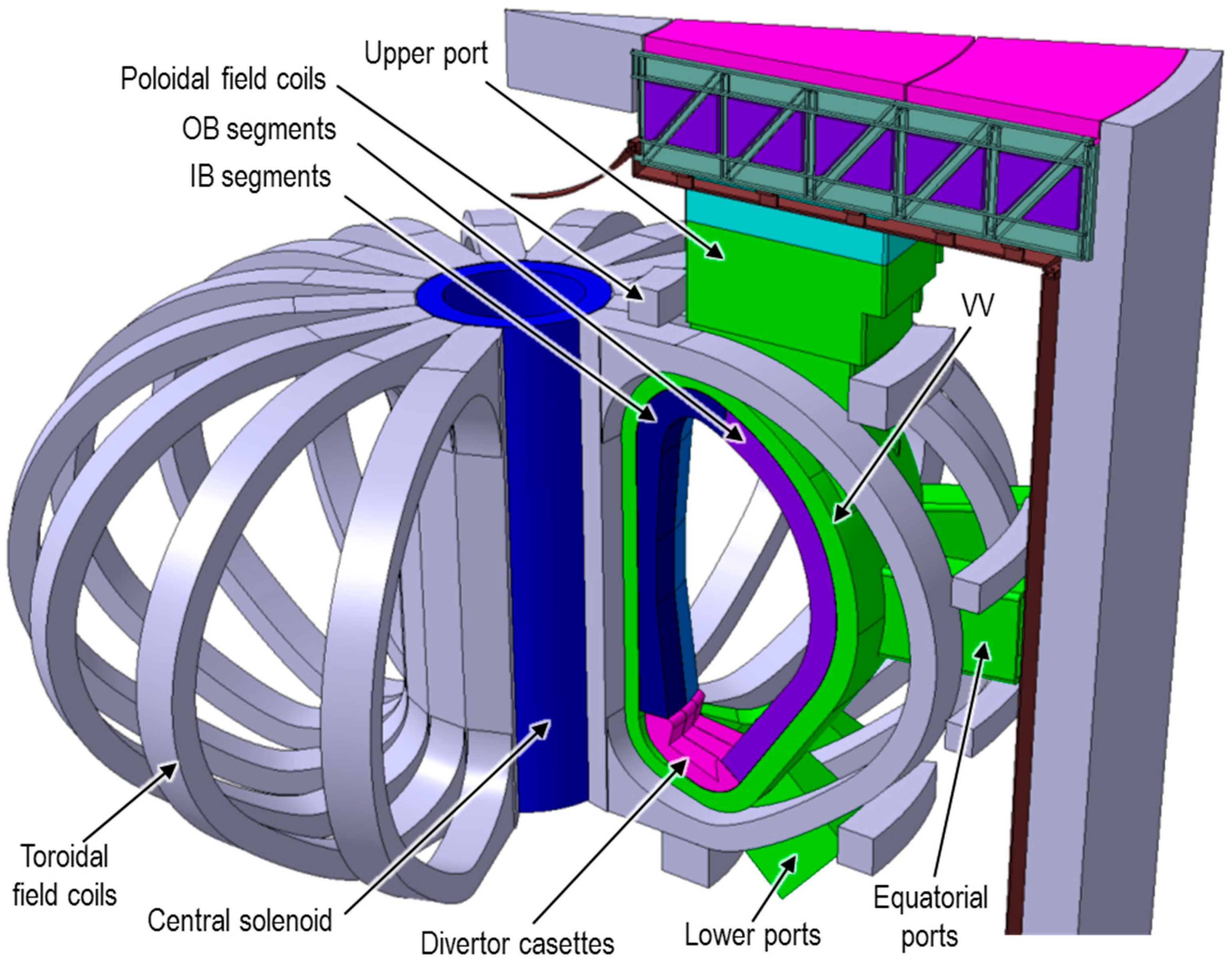
2. DEMO Plant Baseline Description, the DEMO Breeding Blanket System (BBS) and High Level Requirements

Figure 1 depicts the latest DEMO baseline configuration as of 2017, on which the last part of the PCD phase after the strategy re-evaluation has been based [7]. This baseline consists of a single-null tokamak with an aspect ratio of 3.1 and major/minor radius of 9.0/2.9 m, a fusion power of 1998 MW and ~500 MWe, plasma volume of 2466 m3, 16 toroidal field (TF) coils (i.e., 16 sectors), a neutron wall load (NWL) of ~1 MW/m2, burn time of 7200 s and a dwell time of <600 s.
In each sector, the BB is required to be split into so-called segments (Figure 1). There are inboard (IB) and outboard (OB) segments, and for each, there are two IB segments, left and right IB (LIB and RIB, respectively) and left, central and right OB (LOB, COB and ROB, respectively). This allows the required vertical remote maintenance of the BB segments [4]. These segments are supported on the inner shell of the vacuum vessel (VV) by a system of structures at the back of the segments that constitutes the so-called BB attachment (or BB support) system [8]. These structures consists mainly of keys and pads protruding the segments and matching the corresponding pockets and pads performed onto the inner shell of the VV, restraining the segments and transferring the loads to the VV during normal and off-normal conditions. The feeding pipework for the coolant and tritium carrier fluids from and to the BB segments is mainly routed through the upper port, yet a minor part of this pipework can be routed through the lower port for some BB concepts for draining reasons.
A characteristic of this baseline is the (radial) thinning of the BB segments with respect to previous plant designs, motivated by a reduction in plant size, while still fulfilling shielding requirements [4]. This imposes a harder requirement on the BB system, which has to breed enough tritium in a smaller volume and still fulfil the DEMO stakeholder requirement of achieving a self-sufficient tritium fuel cycle. For this, it is required that the BB breeds 5% more tritium than it is burnt through fusion to account for a margin due to tritium loss budget in the fuel cycle, thus, a required tritium breeding ratio (TBRreq) of TBRreq = 1.05 [9]. This should not be confused with the required target TBR (TBR ≥ 1.15) to take into account not only the fuel cycle margin but also neutronic modeling margins [9]. Other key nuclear top-level requirements on the BB, mainly related to the shielding of VV and TF coils, are reported in [4].
This baseline assumes the in-vessel components (IVCs) to be manufactured with the reduced activation ferritic-martensitic steel EUROFER97 (AISI 316SS ITER-grade for the VV). A progressive approach for the BB operation is then anticipated [7], with a total DEMO plant lifetime of the blanket lifetime of ~7 full power years (fpy), in which a so-called “starter” BB set will have to last ~2 fpy and a “second” BB set will cover the remaining ~5 fpy. The rationale behind both BB set lifetimes is discussed in [10].
One of the key design integration issue (KDII) studies conducted during the PCD phase has been the wall protection strategy in DEMO [11]. This strategy entails using so-called protection limiters. The presence of these elements reduces the heat flux requirements on the FW of the BB to localized peaks of ~1 MW/m2.
The BB main interfacing systems are the heating & current drive (H&CD), fueling lines, primary heat transfer system (PHTS), remote maintenance (RM), vacuum vessel pressure suppression system (VVPSS) and tritium extraction and removal (TER) system. The list of BB system requirements is reported in [12] and the requirements regarding these interfaces are addressed in the baseline. An overview of the systems engineering approach to the system and interface requirements can be found in [13].
As stated in Section 1, the two driver BB candidate concepts for the EU DEMO are the WCLL and HCPB. Their architecture, main performance figures and associated TER systems are provided in the following section.

3. The WCLL BB Concept

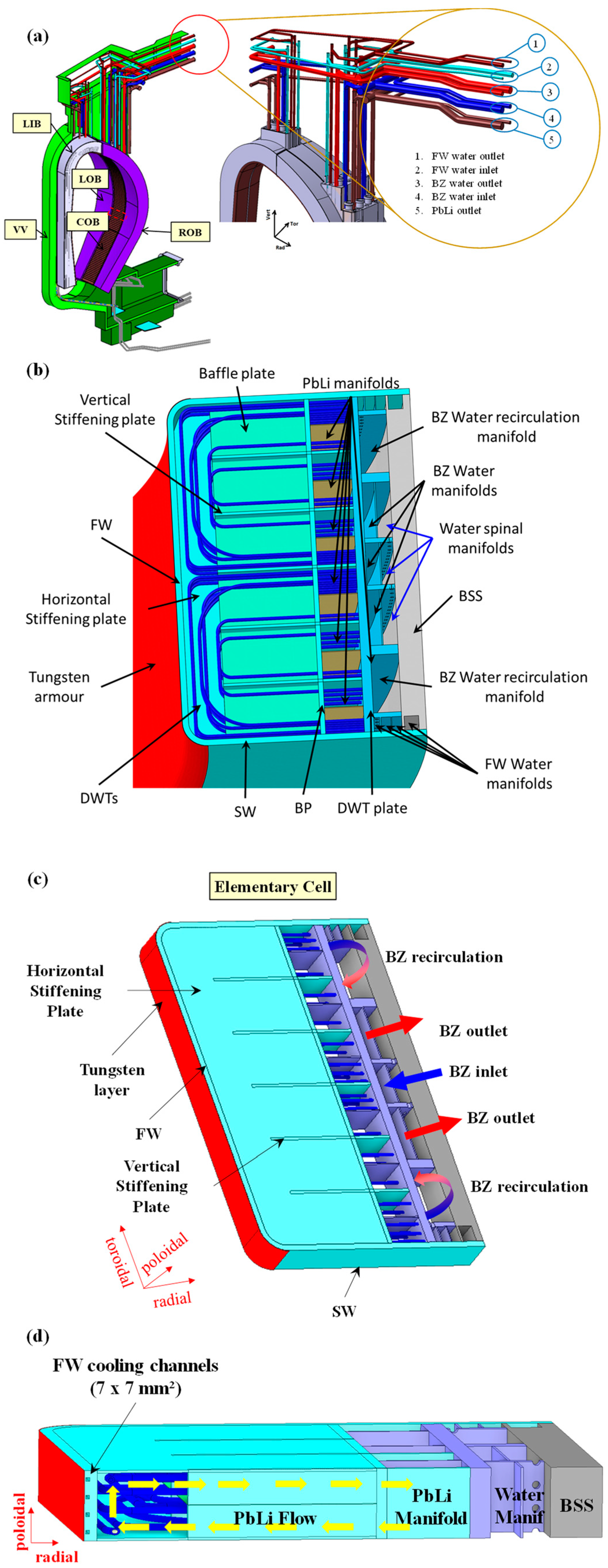
3.1. General WCLL BB Architecture Description

The current WCLL BB architecture [14] is the result of several modifications carried out during the PCD phase [15,16,17,18], driven by the necessity to cope with neutronic, thermal–hydraulic, structural and manufacturing requirements. Thus, the initial BB layout set-up by CEA [19], envisaging BB segments divided into sub-modules, was substituted by continuous BB segments (Figure 2a) which could ensure the maximization of the TBR whilst reducing neutronic streaming, a higher capability to withstand electromagnetic (EM) loads and the minimization of the interfaces with PbLi and water coolant loops.
Also, the coolant thermal cycle was slightly modified, with the reduction in the BB thermal rise from 40 °C (285–325 °C) to 33 °C (295–328 °C). This modification was mainly driven by the adoption of a once-through steam generator (OTSG) in place of the U-tube one [20,21]. Indeed, in view of a direct coupling between the primary heat transfer system (PHTS) and the power conversion system (PCS), this kind of steam generator is the most suitable since they are characterized by very low thermal inertia.
All the aforementioned modifications lead to the current WCLL BB layout (Figure 2). Each segment is constituted by an external steel envelop represented by the FW-SW structure, cooled using square channels, and the back supporting structure (BSS), a stiff backbone whose main goals are supporting both the segment weight and EM loads due to unexpected plasma transients. On the other hand, the internals of the segment are mainly occupied by the breeding zone (BZ), a grid of vertical and horizontal stiffening plates filled with the breeder and neutron multiplier medium and cooled by means of bundles of double walled tubes (DWTs), and the manifold region, where both PbLi and water are routed to and extracted from the BZ. Moreover, from the functional point of view, each segment can be thought as a poloidal stack of identical elementary cells, called breeding units (BUs) or “slices” (Figure 2c,d). In particular, a slice is that region delimited by two successive horizontal (toroidal–radial) stiffening plates.
The current BB layout is the result of different optimization campaigns of analysis that have been performed during the PCD phase [22,23] with the aim of simultaneously fulfilling neutronic, thermal–hydraulic and structural requirements. However, some modifications are still necessary and are going to be implemented in the current conceptual phase.

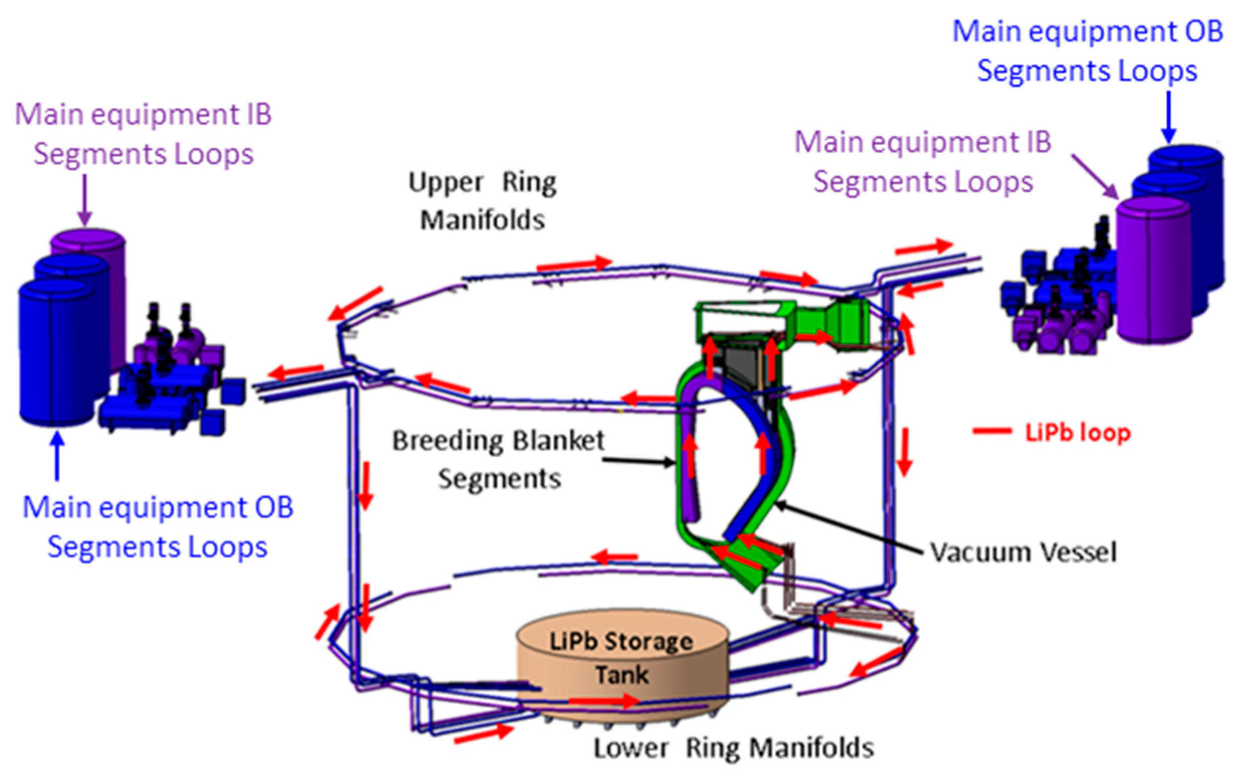
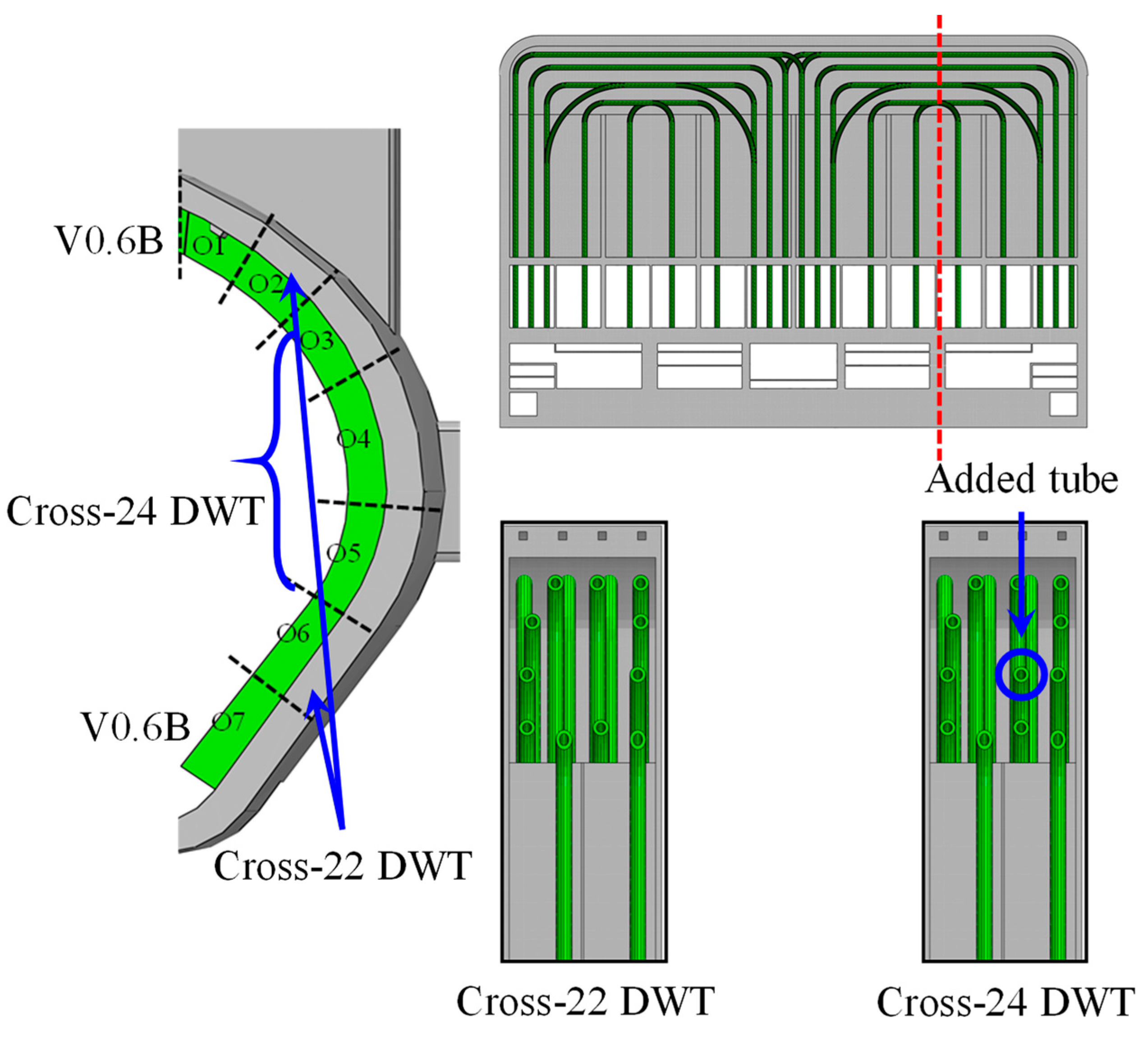
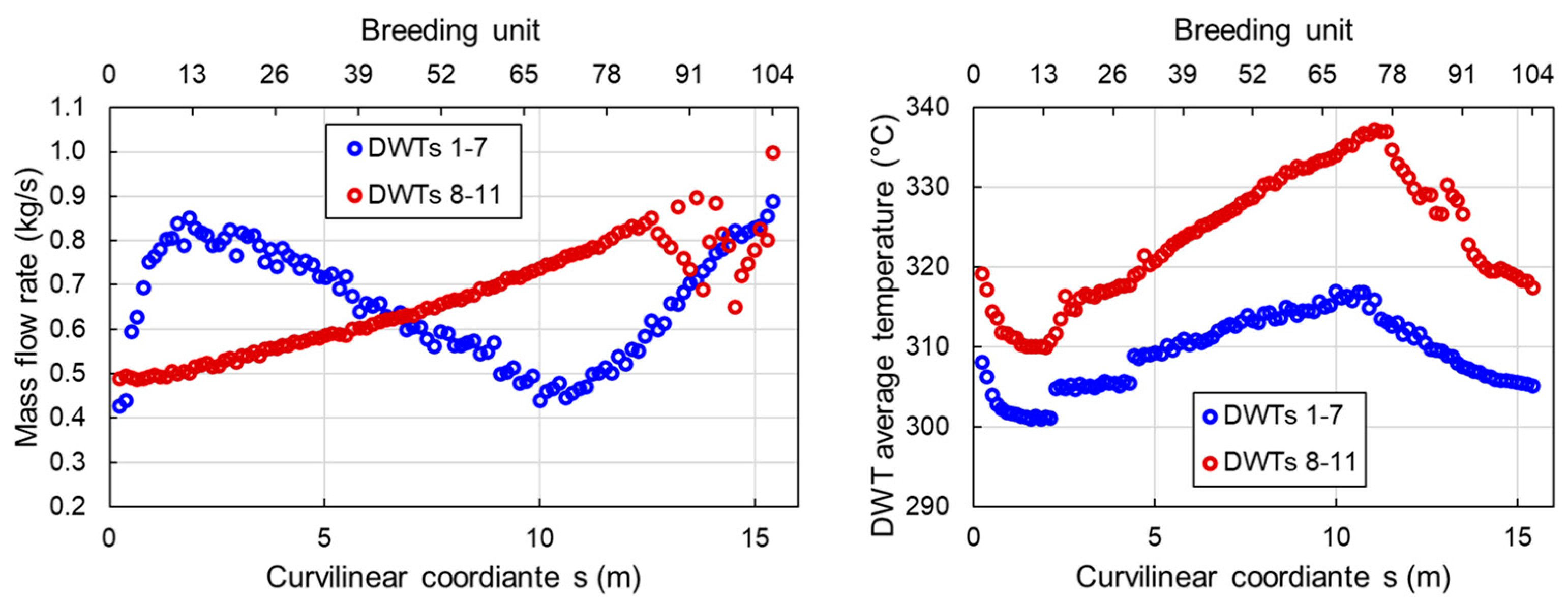
3.2. The WCLL TER System

The WCLL TER system is composed of six independent loops, four of which feed the BB OB sectors (1 loop per 4 sectors), while the remaining two feed the IB sectors (one loop per eight sectors) [24]. More than 3.5 km of pipes are necessary to connect the BB segments to the TER components and to the storage tank (Figure 3), which is shared by the six loops and located in the lowest part of the tokamak building.
About 1400 m3 of eutectic lithium–lead (PbLi) will be needed to fill up the loops and ensure the fulfillment of their functions, which comprise the extraction of tritium, the circulation, heating and purification of the alloy and the shielding of radioactivity. To accomplish these tasks, each loop includes a tritium extraction unit (TEU), a pumping system and a purification system.
The PbLi circulation is ensured by a mechanical pump with magnetic coupling between the motor and the pump shaft. This solution was studied to minimize the risk of PbLi leakages and the release of radioactive materials. The choice of mechanical pumps over electromagnetic ones is mainly linked to their much higher efficiency. The pumping system design leveraged the huge experience gathered by ENEA in operating and designing pumping systems for lead alloys for generation IV fission reactors [25].
The purification system is in turn divided into three subsystems, aiming at removing helium, corrosion products and activated products (coming from direct activation of lead, such as Po, Hg, and Tl) from PbLi. R&D activities dedicated to the characterization of the three systems at laboratory scale are being carried out at CV Řež with the MELILOO and VOSA facilities. Furthermore, helium solubility in PbLi is being investigated via experiments and molecular dynamics modeling [26].
Three technologies are currently under investigation for extracting tritium from PbLi in the TEU: the gas–liquid contactor, the permeator against vacuum [27] and the liquid vacuum contactor. Mock-ups [28,29] of TEU based on these three technologies are being tested in TRIEX-II [30] and CLIPPER [31] facilities; the testing activities are also supported by the development of modeling tools [32]. In parallel, extensive R&D is ongoing at CIEMAT, KIT, UKAEA and ENEA to reduce the existing uncertainties on the parameters for tritium transport in PbLi and structural materials [33,34].

3.3. WCLL Main Performance Achievements
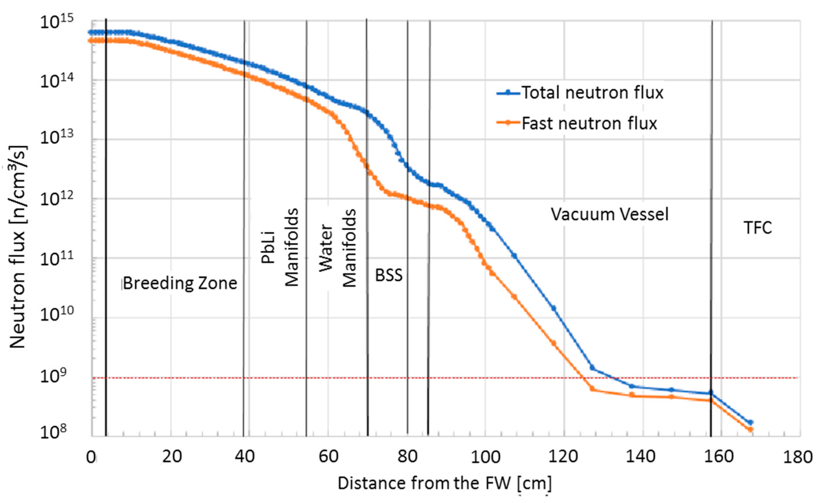
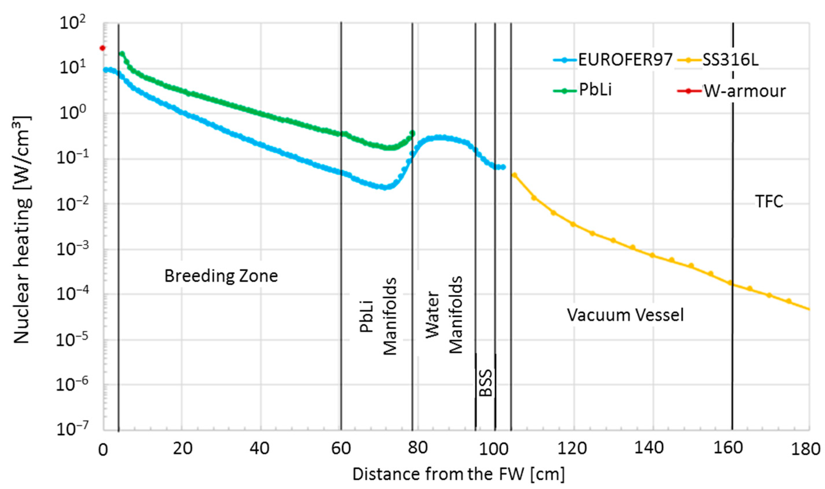
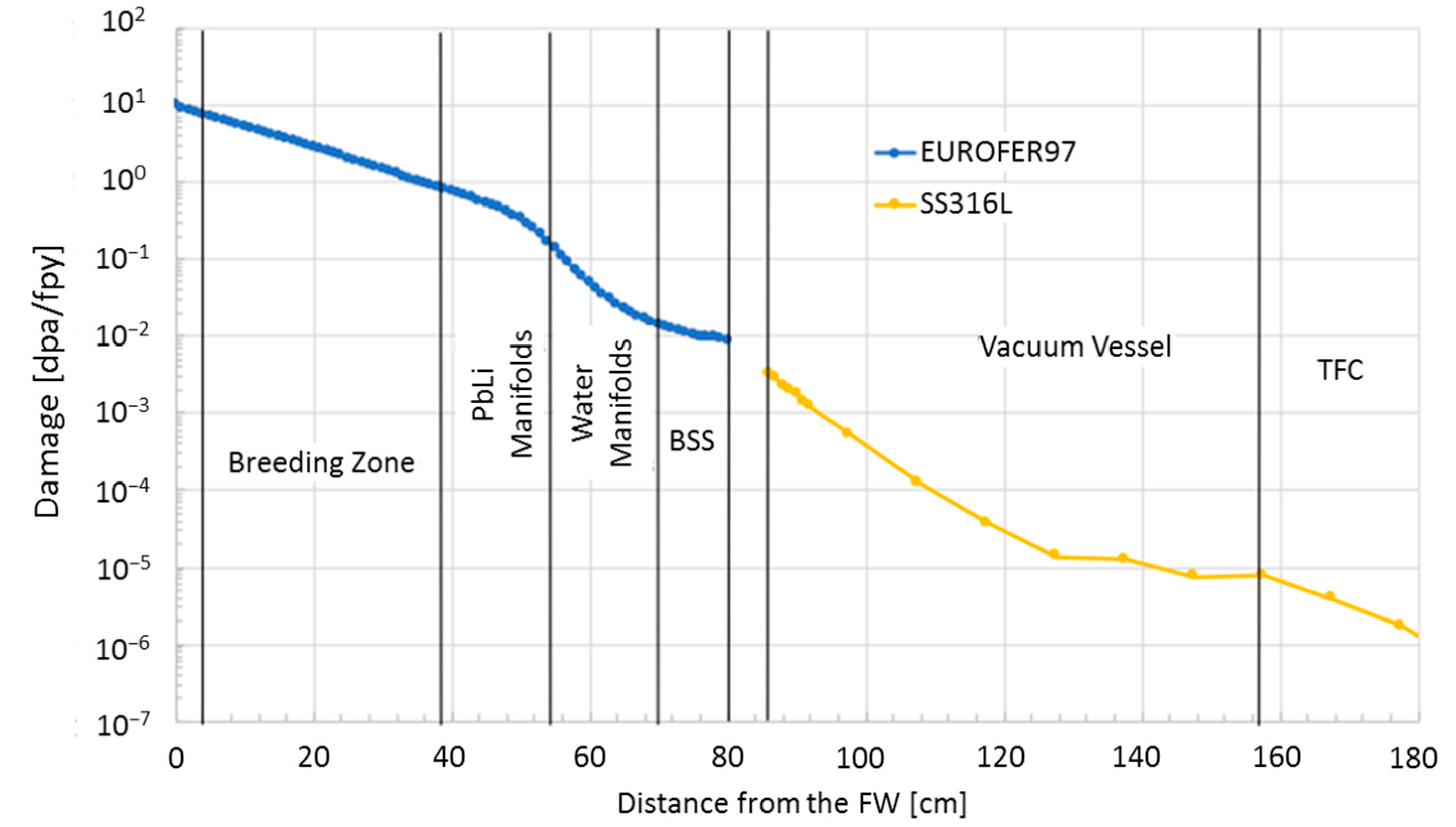
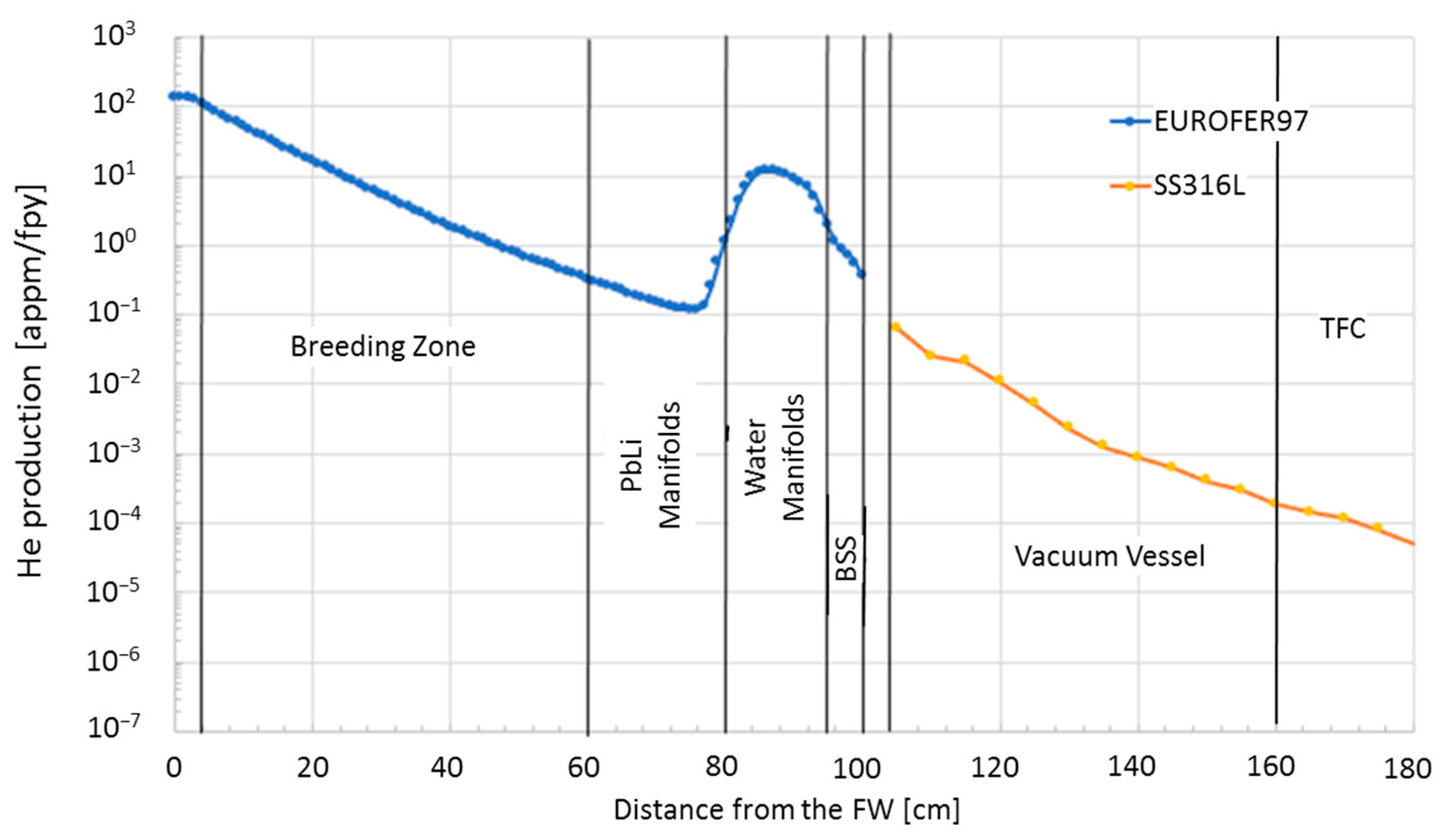
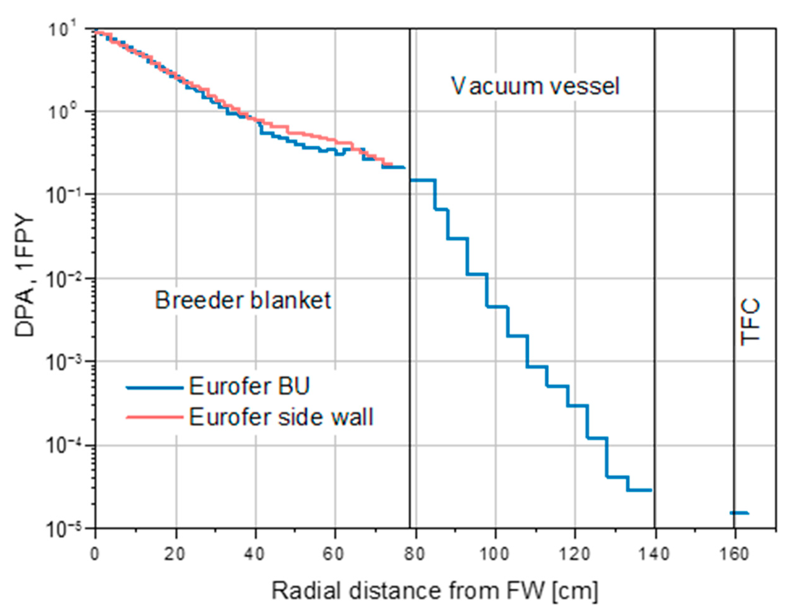
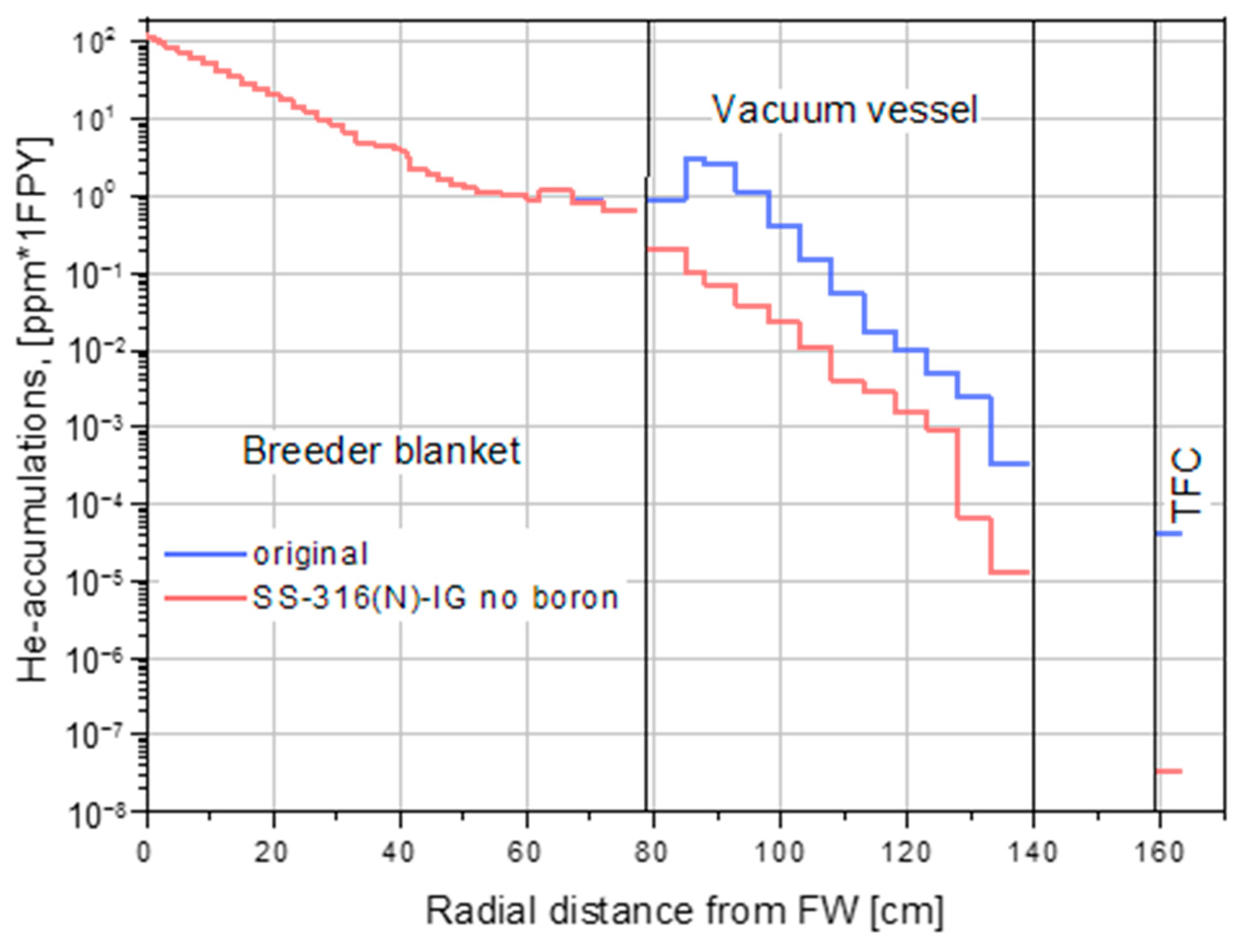
3.3.1. Neutronics

Neutronic analyses carried out until 2020 [35] have demonstrated the effectiveness of the WCLL BB performances both in terms of tritium generation, with a calculated TBR equal to 1.15, and shielding capabilities. However, during the last two years some minor modifications were necessary to the BB design, mainly in terms of the number of cooling structures (both FW channels and DWTs) in some regions of the BB [36]. Since the poloidal distribution of the plasma heat flux and the deposited neutronic volumetric nuclear heating is not uniform, some modifications were performed to avoid the insurgence of local temperature hot-spots.
Thus, three-dimensional coupled neutron and gamma transport simulations have been performed according to the guidelines on neutronic studies [9] utilizing the MCNP5v1.6 Monte Carlo code [37] complemented with the Joint Evaluated Fusion File (JEFF) 3.3 nuclear data libraries [38]. The analyses have been performed using a fully heterogeneous model of the BB/manifold system.
Results obtained from the analyses showed that a TBR of 1.14 is calculated for the WCLL BB, thus, slightly below the requested value of 1.15. Concerning the former layout and calculations [35], the amount of water in both the inboard and outboard sectors of the BB is increased because of both the higher number of DWTs in the BZ and FW channels in the OB regions close to the divertor. Water (especially that in FW) has a double effect: it moderates the neutrons enhancing the probability that they could interact with the lithium nuclei (i.e., the neutron absorption cross section on lithium increases with the reduction in the incident neutron energy), but it also drastically inhibits the neutron streaming in the innermost breeding blanket sectors. Thus, further optimization of the BZ performance in terms of tritium generation has to be taken into account, to achieve the required TBR design target.
On the other hand, the WCLL BB shows excellent shielding performance towards the VV and the toroidal field coils (TFC). Indeed, the design limits for the fast neutron flux on the TFC (109 n/cm2s), the integrated radiation damage on the VV (2.75 dpa in 6 FPY) and the integrated helium production in the VV for re-welding purposes (1 appm in 6 FPY) are fully satisfied.
Figure 4, Figure 5, Figure 6 and Figure 7 depict the radial behavior of the nuclear heating, neutron flux, neutronic damage and helium production calculated for the WCLL BB, respectively.

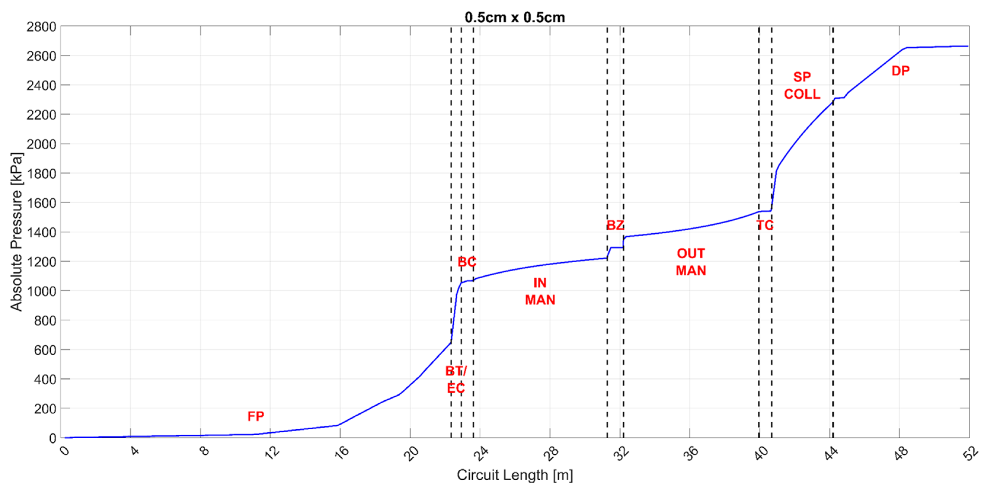
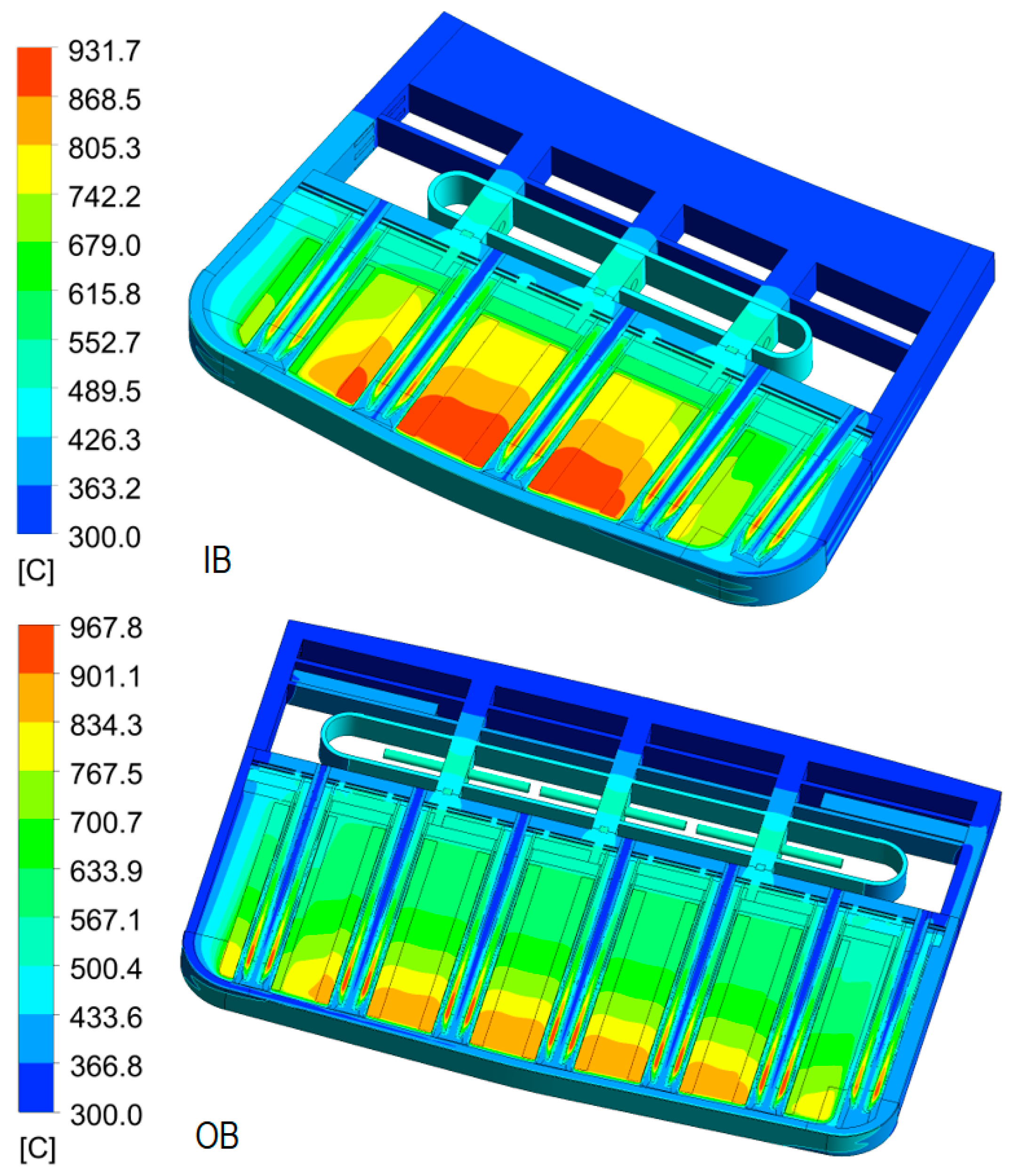
3.3.2. Thermal–Hydraulics

Different types of steady-state thermal and thermal–hydraulic analyses have been carried out on the WCLL BB. The main aim of these calculations has been the determination of the thermal field arising within the WCLL BB structures to check that the recommended maximum temperature of 550 C is not surpassed and that the coolant flow distributions among the different BUs are fed in parallel by the manifold system.
The first batch of analyses has been aimed at the optimization of the DWT layout and FW channels in the different poloidal regions of the WCLL COB segment. Indeed, it was found that the DWT layout achieved at the end of the PCD phase named v0.6B [14] was not able to effectively remove the heat power generated in the BZ [35] while maintaining the maximum temperature below the suggested value of 550 C (grey areas in Figure 8).
Moreover, since the poloidal distribution of the volumetric deposited heat power is not uniform, it was decided to sub-divide the COB segment in seven regions and identify a DWT layout for each of them. A similar strategy was adopted for the spacing of the FW channels. In this case, the driving factor was the non-uniform heat flux distribution coming from the plasma, as described in [11]. Steady-state thermal analyses reproducing the flat-top normal operation scenario of the DEMO reactor have been carried out. The heat flux distribution computed in [11] has been imposed on the tungsten armor facing the plasma, while the volumetric nuclear heating computed via neutronic analyses [35] has been considered for both structural and breeder materials. In all the calculations, the PbLi has been conservatively considered stagnant.
Concerning the FW channel distribution, it was found that four channels per elementary cell can remove the heat flux deposited by plasma in five out of seven poloidal regions. Six channels are needed instead in the two regions closer to the divertor (O6 and O7 in Figure 9). As far as the DWT layouts are concerned, three different alternatives were taken into account. In particular, regions O1 and O7 have been equipped with the former DWT layout (the v06b), and O2 and O6 has been equipped with the tube layout named cross-22 DWT, in which only a small modification of the tube layout was made to fight a temperature hotspot located in correspondence of the toroidal symmetry plane of the elementary cell. Finally, the cross-24 DWT configuration has been chosen for O3, O4 and O5 regions, thus, increasing the number of tubes per slice from 22 to 24 [39].
Concerning the IB segments, a similar work is being carried out at CEA. Even though the work is still ongoing, a first outcome was the need for increasing the number of DWTs in each elementary cell, also in the IB BZ, passing from 20 to 22. This has been already included in nuclear analysis reported in Section 3.3.1.
Concerning the assessment of the BZ water manifold behavior, a global analysis adopting a hybrid modeling approach was performed [14,40]. The DWTs assembly of each half BU (11 pipes) is replaced by only two equivalent tubes modeled using an equivalent porous model specifically developed to mimic the hydraulic behavior of DWTs. Then, the thermal–hydraulic behavior of the whole manifold was studied using the commercial tool STAR-CCM+, version 15.02.009. Analysis highlighted a quite important difference in the mass flow rates and outlet temperatures along the poloidal coordinate of the segment (Figure 10), suggesting that an accurate orifice distribution is needed to determine whether the manifold system will remain the same.

3.3.3. Magneto-Hydrodynamics (MHD)

A peculiar aspect of the WCLL BB is the presence of a liquid metal circulating in the in-vessel components, where a significant magnetic field and ferromagnetic materials are present. Thus, magneto-hydrodynamic effects (MHD) significantly affect the thermal–hydraulic behavior of the PbLi, since its temperature, pressure and velocity profiles are influenced by the high magnetic field values present in the BB. During the PCD phase, an effort has been undertaken to increase the modeling capability of these coupled effects. MHD investigations carried out may be divided into two groups of activities, one focusing on the hydraulic behavior of the PbLi flow in the in-vessel circuit and manifold system [41] and the other devoted to assess the heat-transfer and flow behavior at the elementary cell level [42,43,44].
Concerning the first group of activities, the updated pressure evolution in the COB segment, including feeding and draining pipes (FP and DP), is reported in Figure 11. The analysis represents an update of the work performed in [45]. It is clear how the main contributions to the global pressure drop come from the feeding and draining pipes, where PbLi crosses regions are characterized by an intense magnetic field; from the bottom expansion chamber, where PbLi flow coming from the inlet pipe spreads to the six parallel manifolds and from the segment spinal collector, where PbLi experiences a significant fluid velocity. It is worth underlining that in this calculation no electric insulation has been considered for the feeding and draining pipes. The estimated total pressure drop is about 2.6 MPa, higher than the maximum value of 2.0 MPa. Moreover, since magnetic fields on the IB side are higher, higher pressure drops are expected for the IB segments. These values suggest that a revision of either the manifold geometry or the PbLi mass flow rates is needed.
As far as the second group of activities is concerned, local MHD analyses have been performed with direct numerical simulation adopting ANSYS CFX code to investigate the heat transfer in the BZ in presence of both the toroidal and the poloidal components of the magnetic field. Since the elementary cell has a quite complex shape, calculations have been limited to the equatorial elementary cell region close to the FW, where the DWTs are barely perpendicular to the PbLi flow direction.
Preliminary results [44] have shown that medium size vortices develop between the rows of pipes (Figure 12). Some differences may be spotted when compared to the purely toroidal magnetic field case [42]; the vortices are larger in size and seem to develop around the entire row of pipes instead of being included between the individual pipes. Higher velocities are envisaged in the proximity of the FW and also in the area close to the baffle plate, where the barrier effect of the fourth DWT row is stronger. On the other hand, no significant differences can be found in the thermal field distribution, since the high magnetic field values tend to suppress convective heat transfer in the BZ.

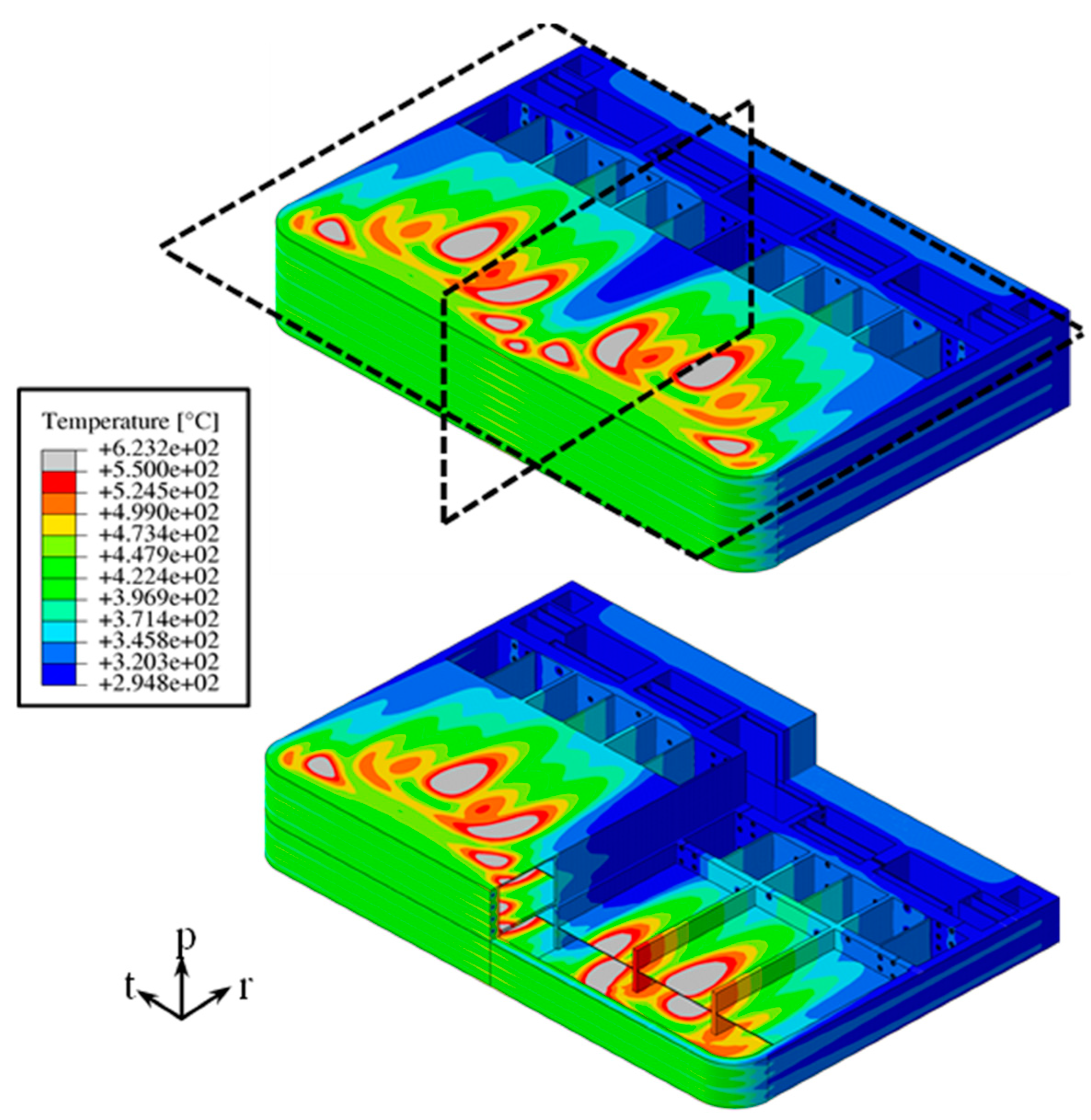
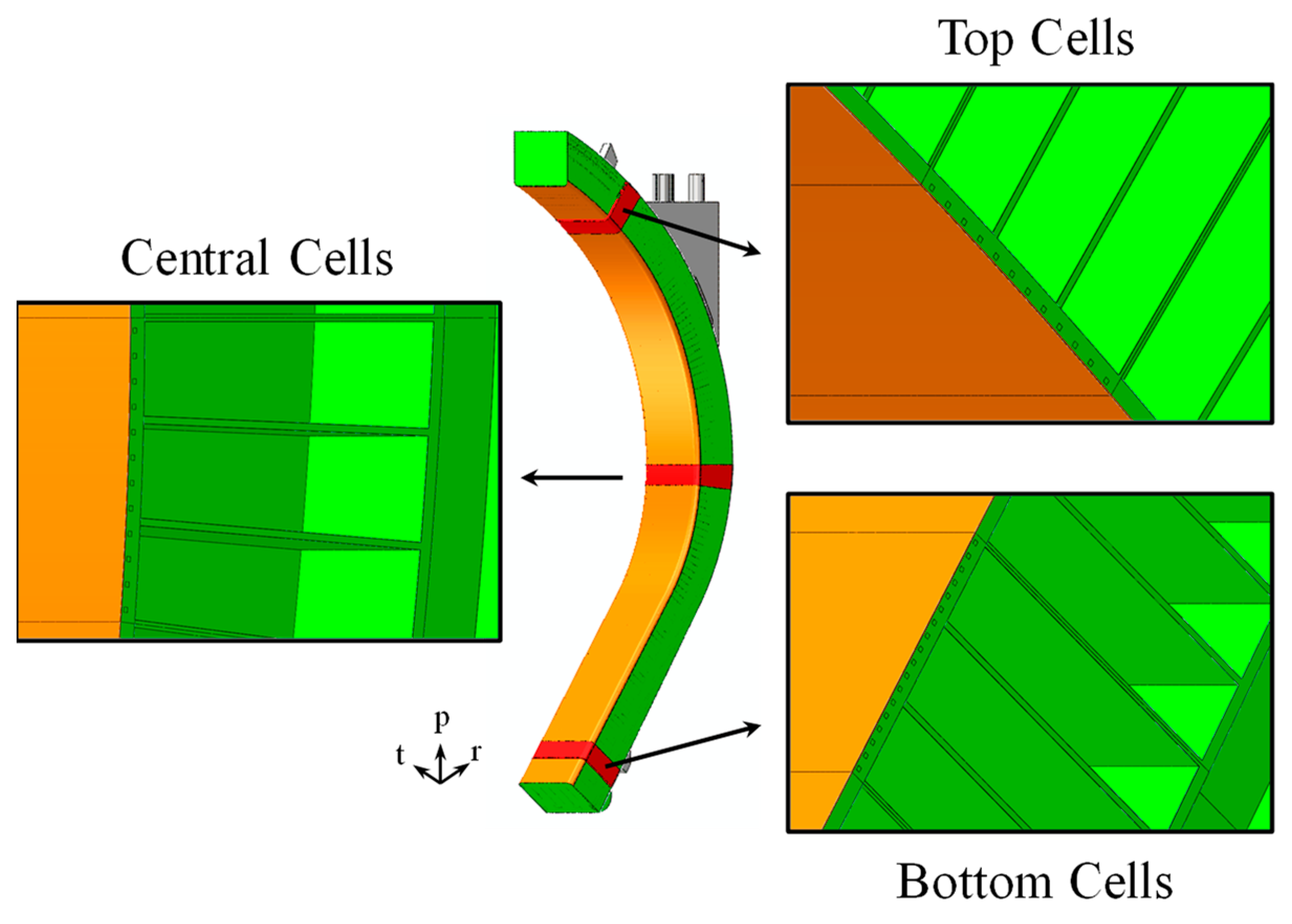
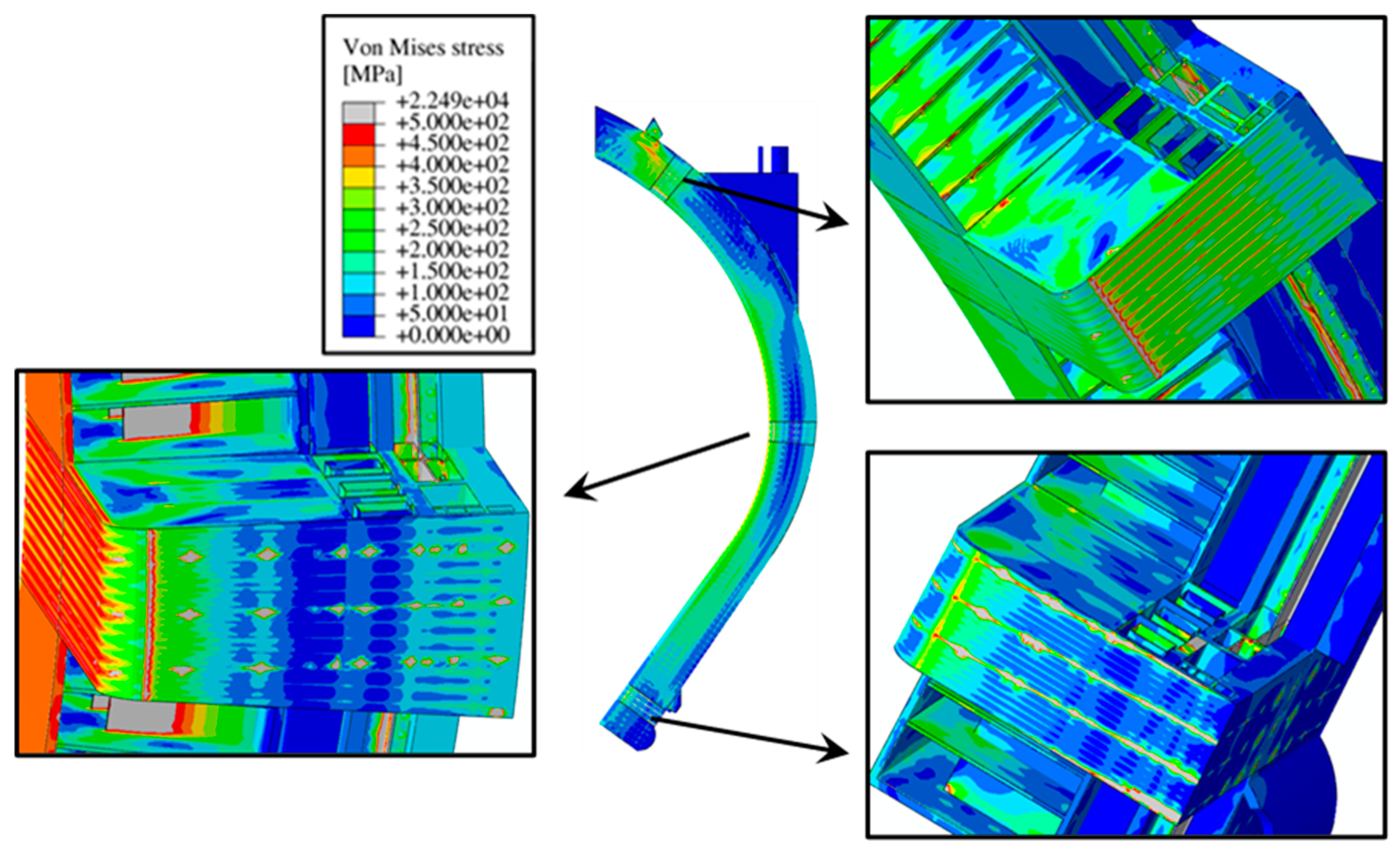
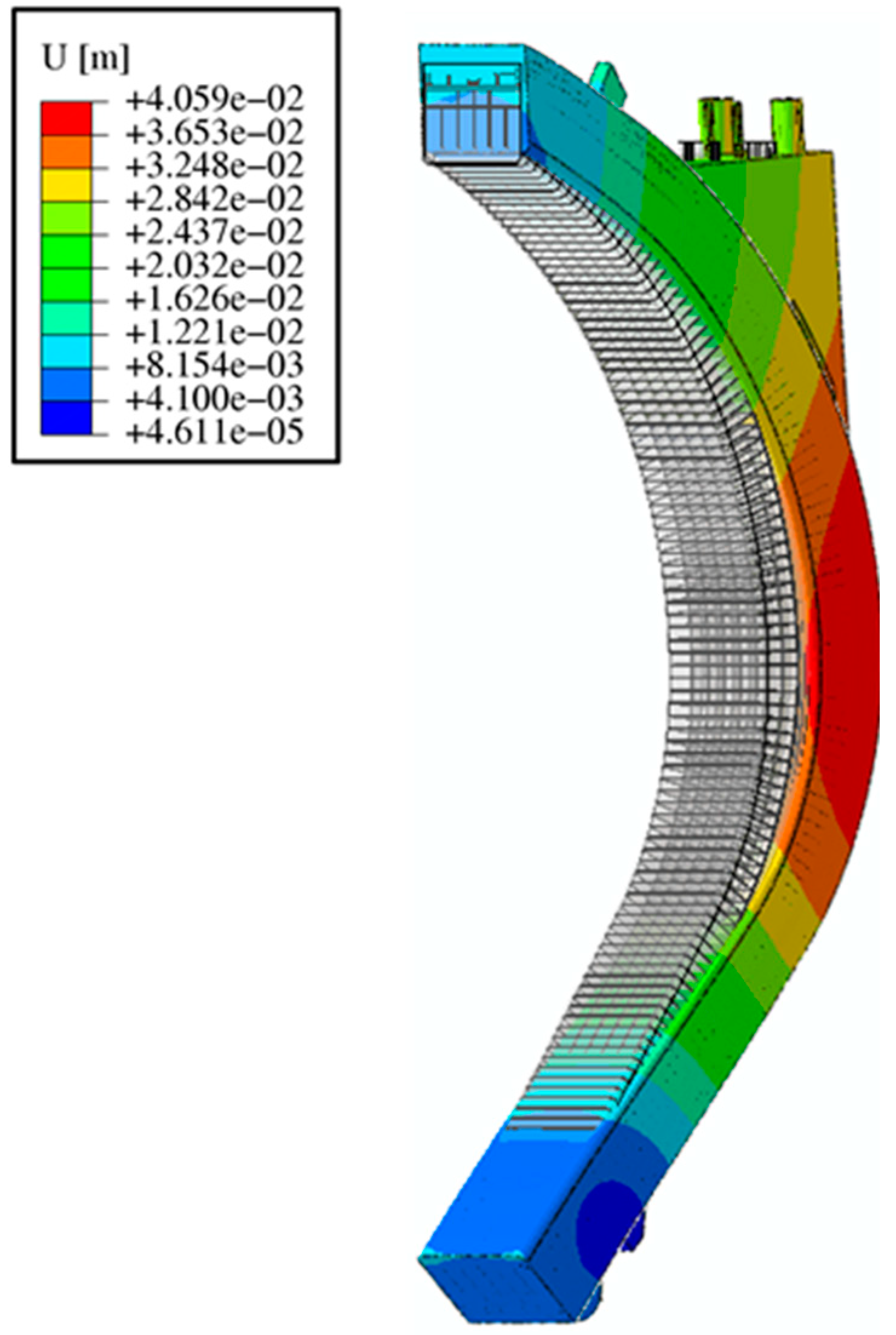
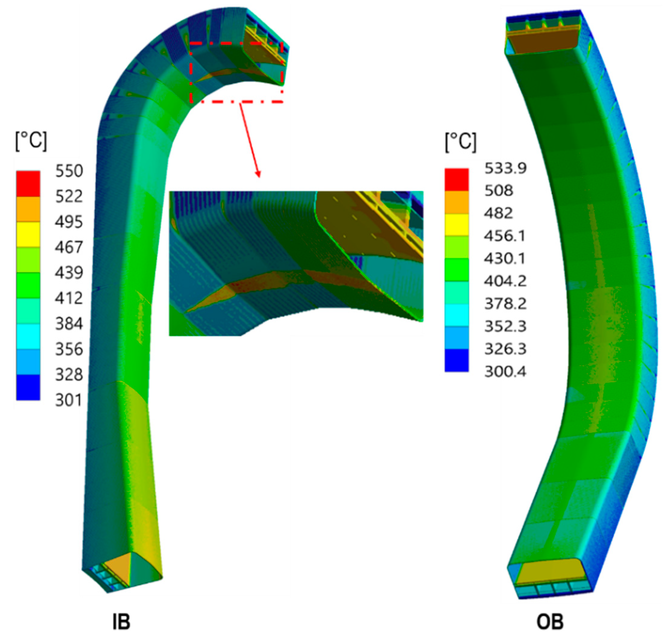
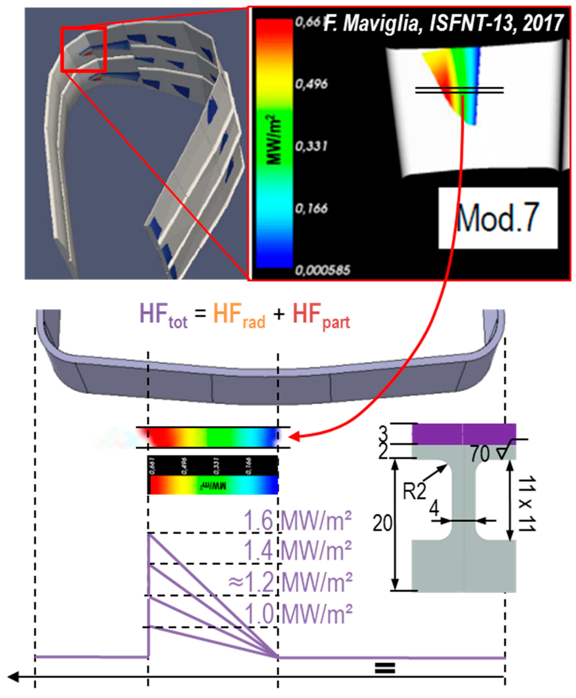
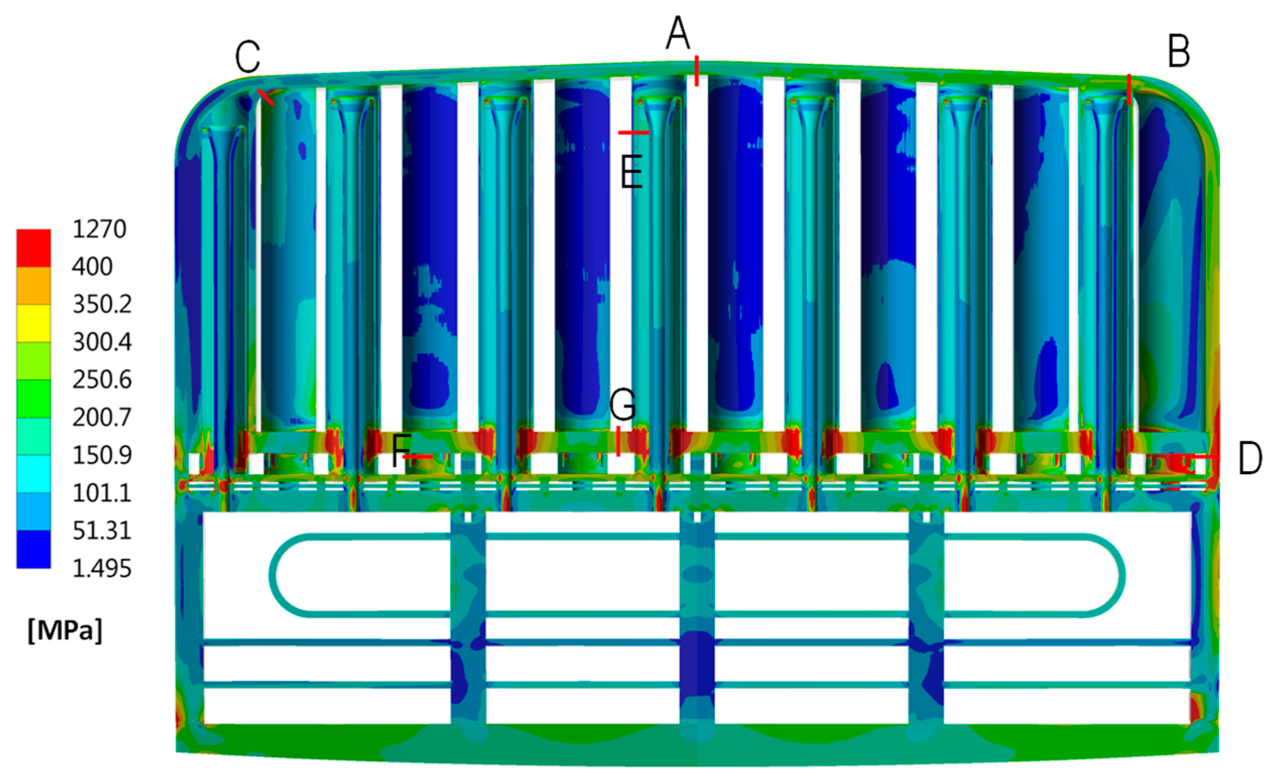
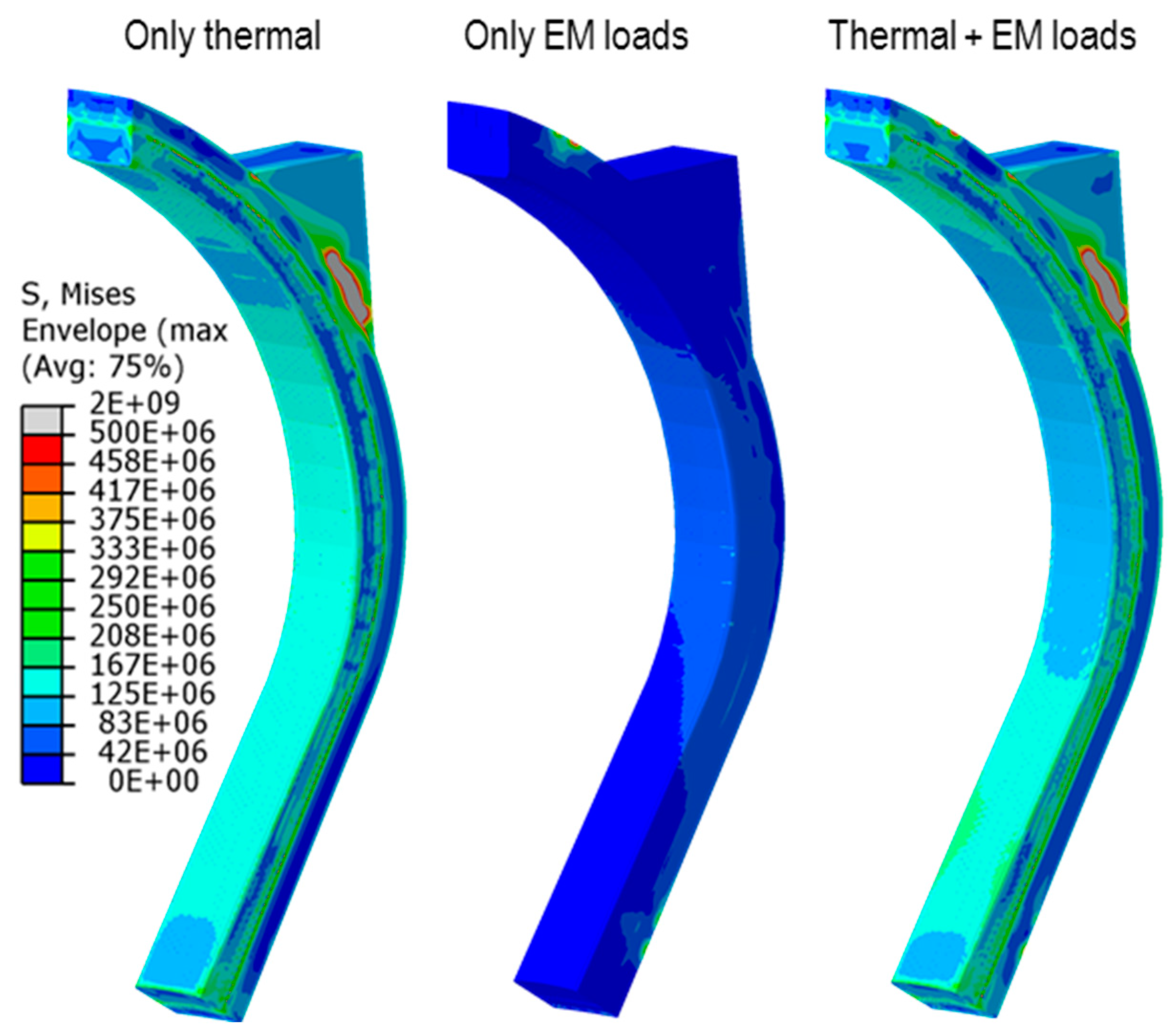
3.3.4. Thermo-Mechanics

Thermo-mechanical analyses have allowed to assess the structural behavior of the WCLL BB. Calculations have been mainly performed on the OB segments adopting the sub-modeling technique. Different loading conditions have been investigated and checked against the rules set by the RCC-MRx design code [46]:
  • Normal operation (NO) loading scenario—Level A in RCC-MRx (Cat. I loads);
  • Up-vertical displacement event (UVDE) scenario—Level C in RCC-MRx (Cat. III loads);
  • Over-pressurization (OP) or in-box LOCA scenario—Level D in RCC-MRx (Cat. IV loads).
The thermo-mechanical analyses were performed in two steps. In a first phase, thermal deformation field, gravity loads, internal pressure distributions, mechanical restraints and (eventually) electromagnetic loads were applied to the entire segment in order to evaluate its global response. Successively, once the most stressed areas were identified, local analyses were performed adopting the sub-modeling technique. Concerning the thermal deformation field, in order to apply the different calculated fields reported in Section 3.3.2 to the entire segment, the interpolation technique described in [47] was adopted. The same paper reports also all the details concerning the different loads and boundary conditions, which are not repeated here for the sake of brevity. Once the first global analysis was performed, three areas were identified and selected for the performance of local analyses, as depicted in Figure 13. The sub-modeling technique allows to study a smaller local part of a complete model with a refined mesh, based on the interpolation of the solution from an initial model on the boundary regions of the sub-model, which represents a cut through the larger complete model (Figure 13). Hence, the boundary conditions of the local region are defined by the response of the global model and these, together with the loads and the other condition applied onto the sub-model, determine its solution.
Steady-state analyses were run to assess the thermo-mechanical behavior of the identified COB regions under the selected loading scenarios. The obtained results were analyzed and a stress linearization procedure was performed to verify the fulfilment of the RCC-MRx design criteria corresponding to the different levels, according to the selected loading scenario. Therefore, a proper set of paths was selected, looking at the Von Mises equivalent stress field spatial distribution, in correspondence with the most stressed region of each model. In particular, localized peaks of Von Mises equivalent stress value occurring at the points of application of the electromagnetic forces or mechanical restraints were not taken into account for the evaluation of the RCC-MRx design criteria. As an example, the Von Mises equivalent stress field arising in the NO scenario is shown in Figure 14. while the deformation field amplified with an isotropic factor of 20 is superimposed to the un-deformed model in Figure 15.
The different criteria of the RCC-MRx design code were verified along some paths identified both in the FW-SW complex and the stiffening plate grid. Concerning the verification of the criteria of the RCC-MRx design code, the WCLL COB segment shows good behavior, even though not all the criteria were verified in the paths taken into consideration. In particular, the criterion considering the secondary stresses, namely the immediate plastic flow localization, fails in some paths, probably due to the resistance exerted by the SPs against the thermal expansion. Among the three assessed poloidal regions, the most critical one is the equatorial part of the segment, where a remarkable radial deformation arises due to the action of the attachment system (Figure 15). In the other regions, the predicted structural behavior seems to be promising. Hence, a deep revision of the geometric configuration of the attachment seems to be helpful in order to reduce the stress level within the WCLL COB segment, not only within SPs but also within the FW-SW region. These results highlight, once again, that thermal stresses are probably the main driving factor in the thermo-mechanical design of the BB.

4. The HCPB BB Concept

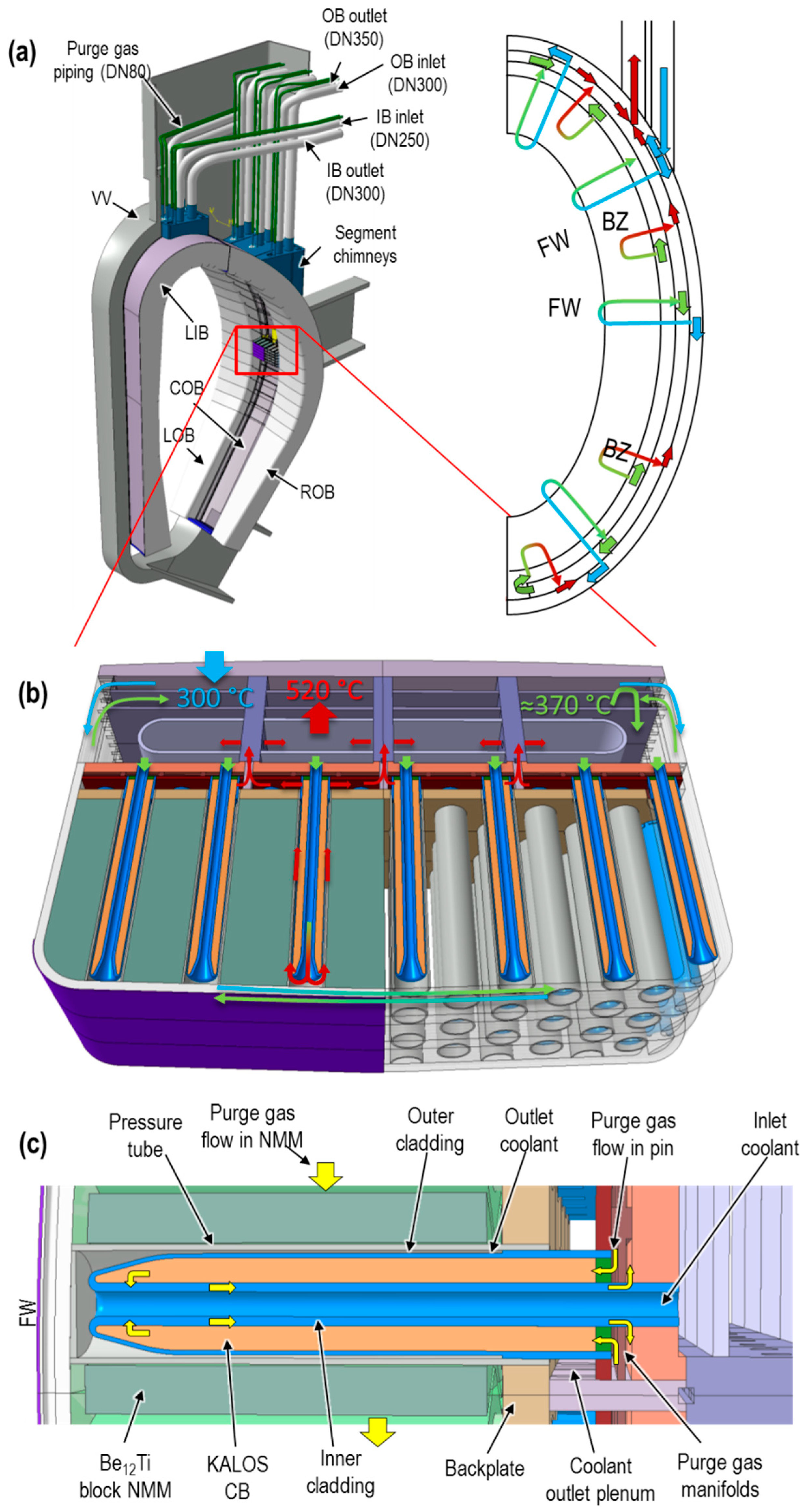
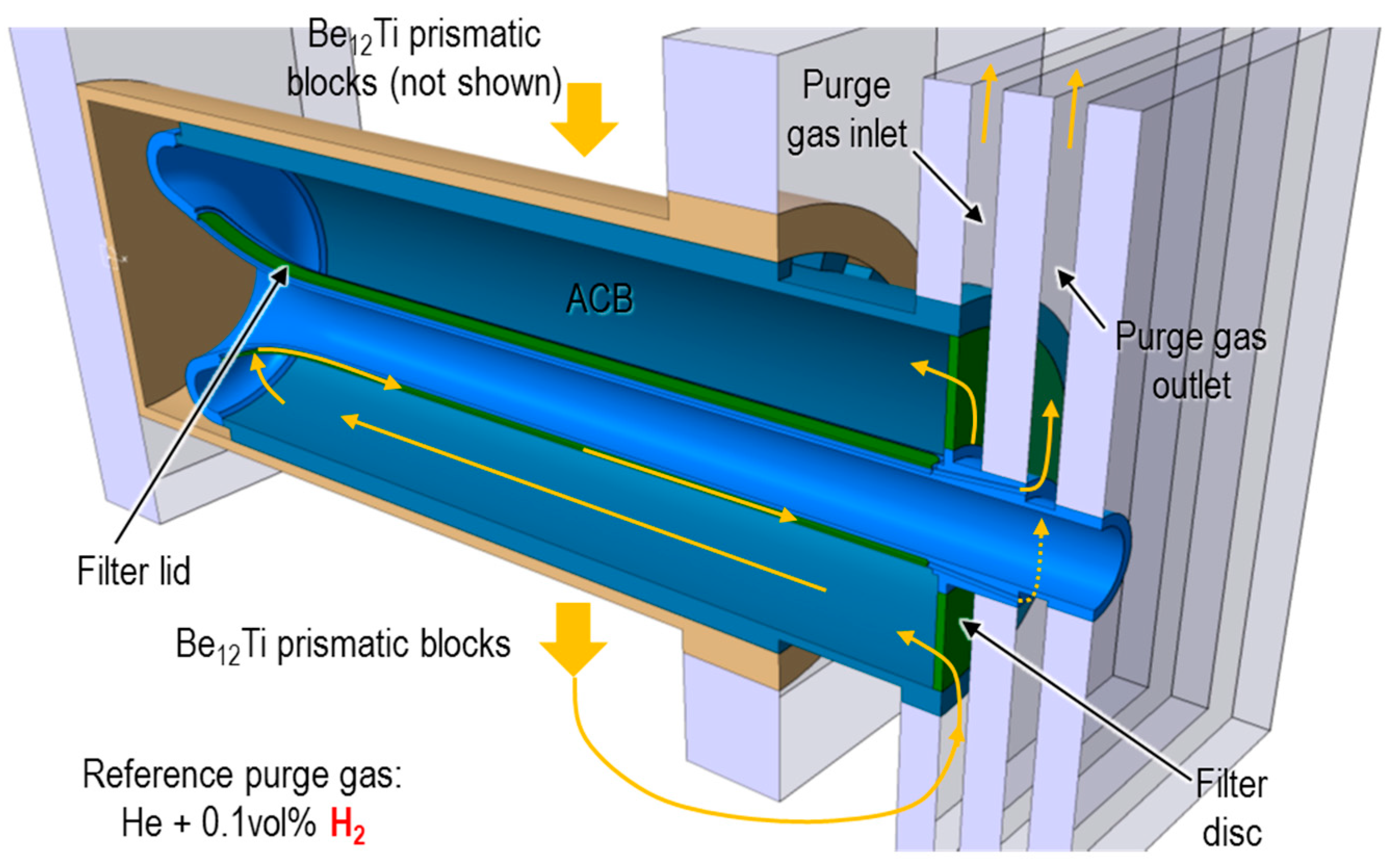
4.1. General HCPB BB Architecture Description

During the PCD phase, the HCPB has undergone several major design revisions in order to adapt to the high level plant requirements and the DEMO stakeholder strategy. These revisions has been usually been triggered by the increased knowledge in the reactor systems integration and the newly adopted “pragmatic approach” in the design of DEMO [48]. Even if the DEMO project clearly states that the system design should lead the R&D [49], this pragmatic approach prioritizes the use of mature technologies, whenever possible.
This new pragmatic approach has had strong implication in the way the DEMO primary heat transfer system (PHTS), a critical interface system for the BB, is understood and designed. Indeed, the largest technology bottleneck identified for a helium-cooled DEMO has been the circulator [50]. These state-of-the-art components allows a parasitic power consumption due to pressure drops in the whole PHTS (including the BB) of ≈6 MW per unit. This limits the total circulating power that the plant can provide, assuming that the number of circulators per plant is necessarily limited due to space and cost constraints. Therefore, limiting the pressure drops to achieve a mature PHTS has been a design driver.
On the other hand, critical issues identified with the tritium retention in beryllium [51,52] have been also a major design driver. During the PCD phase, initial designs of the HCPB based on beryllium pebbles (e.g., [53]) had to be redesigned to use intermetallic beryllium compounds (TiBe12) in the form of prismatic blocks to mitigate the tritium retention problem, as well as to ensure the industrialization of the neutron multiplier.
All in all, these major design revisions of the HCPB have led to the current reference HCPB baseline design, the so-called HCPB “fuel-breeder pin” (or “pin” design). The core of the HCPB “pin” design is based on a radial arrangement of so-called fuel-breeder pins. Each pin consists of two concentric tubes that form the inner and outer cladding (Figure 16c). A filter plate or disc closes the pin at the back, forming an annular volume, which is filled with the tritium breeding material, the so-called KALOS advanced ceramic breeder (ACB) pebbles. The KALOS ACB is a solid solution of Li4SiO4 and Li2TiO3 [54] and the resulting pebble beds reach a packing factor of ≈63%.
Each fuel-breeder pin is inserted in a so-called pressure tube, which joins the FW and the BZ backplate; the FW is a 20 mm thick, U-shaped (toroidally) and actively cooled plate facing the plasma. The plasma side incorporates a 2 mm thick W armor as a sacrificial layer against plasma–wall interactions. The BZ is the formed by the volume between the FW and the BZ backplate. The volume between pins is filled by the neutron multiplier, which is formed by the TiBe12 hexagonal prismatic blocks mounted on the pins through spacers, which leave a space of 1 mm at the assembly. Conduction and radiation through the resulting 1 mm gas gap is the heat transfer mechanism between the blocks and the pins. A purge gas of He as a carrier and an addition of 0.1% vol. H2 (or 200 Pa H2) to promote isotopic exchange between tritium and the purge gas through the functional materials is forced to flow through the pins and the prismatic blocks (Figure 17).
The volume from the BZ backplate to the outer BB backplate is used by the coolant and the purge gas manifolding. He at 8 MPa is used as a coolant due to its neutronic and chemical inertness and best compatibility with the structural material, which is also 9Cr ferritic-martensitic steel EUROFER97. The coolant temperature window in the blanket is 300 °C to 520 °C. The flow scheme is depicted in Figure 16a right and Figure 16b). He coolant at 300 °C enters a BB segment through the upper port and gets distributed to the FW cooling channels through the manifold. The coolant in the FW flows in an alternating manner and it is collected at an average temperature of ≈370 °C in the BZ inlet manifold region, where it is distributed to the pins inner tubes. The coolant increases its temperature flowing through the pins and exits them at ≈520 °C, which is directed through the manifold towards the outlet segment pipe. More details on the HCPB architecture can be found in [55].

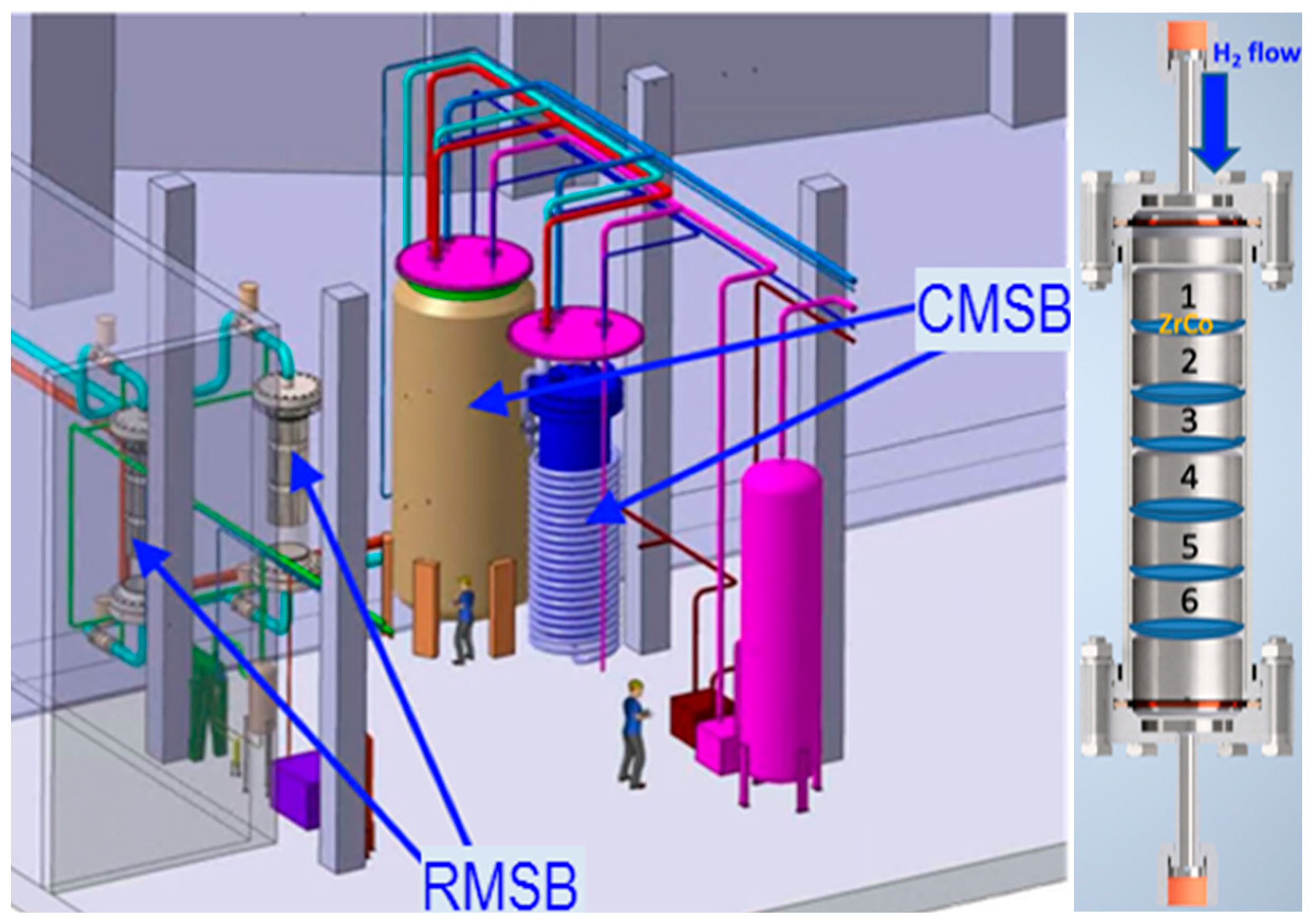
4.2. The HCPB TER System

For the TER function and configuration (Figure 18-left), the helium purge gas at 0.2 MPa and at a volumetric flow rate of 10,000 m3h−1 that contains 200 Pa H2 is used as a reference. Following the purging of the breeder blanket, the purge stream will be diverted through the TER to remove tritium from the helium stream and recycle helium back to the purged blanket. The process of the HCPB TER is based on the trapping/adsorption of Q2O on the RMSB (reactive molecular sieve bed) and the adsorption of Q2 on the CMSB (cryogenic molecular sieve bed) at 77 K or alternatively on getter beds. Despite of the large liquid nitrogen consumption, the tritium adsorption on CMSB at low-pressure TER operation is well-suitable. As it will be explained in Section 5.5, a TER operation at higher pressures (e.g., purge gas at a coolant pressure of 8 MPa) may be desirable in the BB due to reliability reasons. However, liquid nitrogen consumption in the CMSB working at such pressure would become prohibitive and the use of getter beds would be mandatory.
Tritium shall be recovered from the RMSB via catalytic isotope exchange (isotopic exchange between a purge gas H2/D2 and Q2O) and from the CMSB or getter beds by heating up the adsorbing materials to the temperature that will allow the desorbing of most of the trapped tritium.
For the reference TER operation conditions, i.e., 200 Pa H2 content in the purge gas, it is expected that the entire Q2O content, around 6 kg/day, is retained within the RMSB, and a H2/D2 stream is used to flush the RMSB loop while it is heated to promote isotopic exchange. This will reduce the tritium content in the absorbed water that finally will be removed from the bed during full regeneration of the RMSB and transferred for further processing in the tritium plant. Dedicated software is under development aiming to simulate the amount of tritium recovered via the isotopic exchange taking into consideration the design of the RMSB and the real operation conditions. The heating of the molecular sieve is realized through an in-built heat exchanger operated with high-temperature gas provided from a side stream from the TER HCPB purge gas. The software includes the heat transfer calculation between the purge gas stream and the molecular sieve bed and the time evolution of the temperature along the RMSB provides the time evolution of tritium release during the regeneration period.
As far as tritium adsorption on getter beds is concerned, various adsorption materials are under characterization with the final goal to select the materials with high adsorption capacity and low energy consumption during regeneration. Similar to the regeneration of the RMSB system, a helium side stream from the purge gas will be primarily used for the getter beds regeneration. After a 3–4 h adsorption period, the getter beds will be regenerated and the released tritium will be further processed in the DEMO tritium plant.
The reference configuration of the getter beds that will be used for materials testing is shown in Figure 18-right. Several compartments are provided along the getter bed aiming to avoid the getter material conglomeration and to achieve uniform tritium adsorption on each compartment that shall minimize material embrittlement and powderization.
As titanium/zirconium hydrides have a high thermal stability, the thermal desorption of tritium at relatively low temperatures (450–700 °C) is not total. The measurement of residual tritium in the samples is one of the main topics that is also addressed for various reasons, such as safety and maximization of the available tritium in the entire fuel cycle. The reference technology for the residual tritium measurement is based on the total combustion technique, followed by chemical disaggregation of the samples and tritium measurement via the liquid scintillation technique.

4.3. HCPB Main Performance Achievements
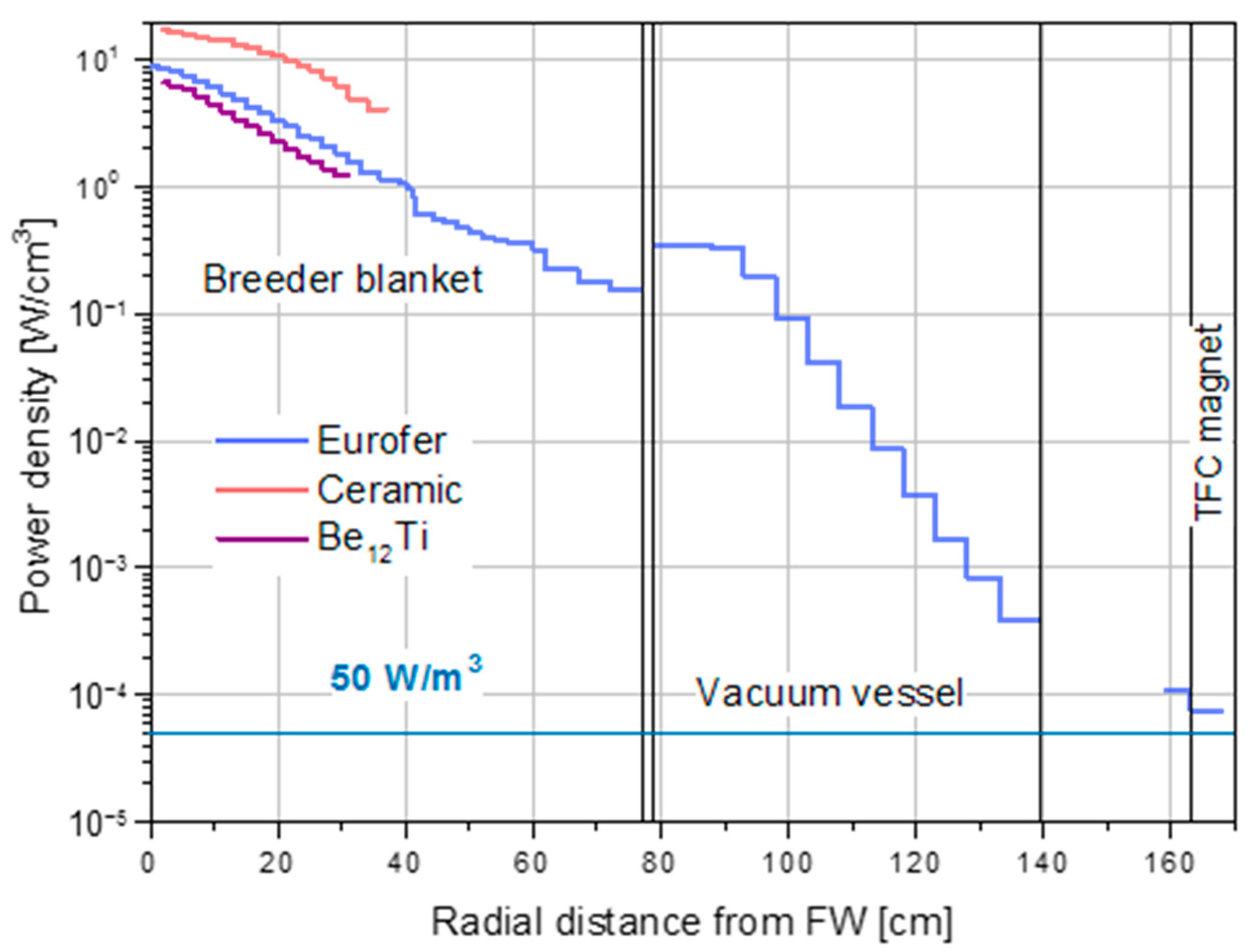
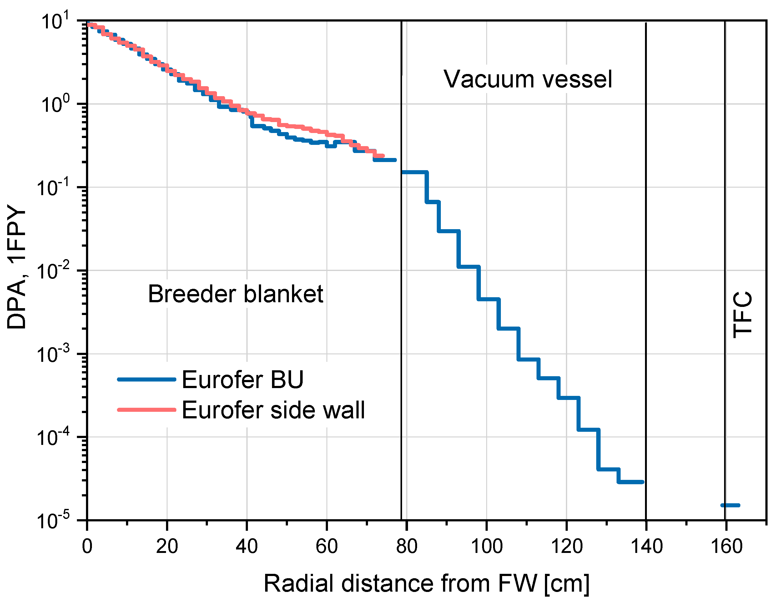
4.3.1. Neutronics

Neutronic analyses have been performed using MCNP5-1.60 code [37] with nuclear data from the JEFF-3.2 library [56]. For heavy-duty MCNP5 runs, such as shielding calculations, a weight window variance reduction technique was applied. This ensures results with good statistics, usually not exceeding ~2% for the cells outside the VV and <0.1% for the plasma-facing components. The master MCNP model has been updated from [57] to include the latest consolidated features of the HCPB. This model represents an 11.25° torus sector of the HCPB enclosed in the DEMO1 BL2017 generic model [57]. The VV on the IB side has a radial thickness of 60 cm including 6 cm thick SS316 steel walls. The cooling of the VV is ensured by water and an ITER-like SS304B7 steel structure is arranged inside the VV to provide its stiffening and shielding performance. TF coils are enclosed in a steel casing. The divertor is modelled as a solid body (60% steel and 40% water), except for three layers facing the plasma. The first and third layers are a 5 mm thick tungsten armor with a 15 mm thick tube layer in between filled with a homogenized mixture of 39.5% W, 17% CuCrZr, 13% Cu and 30% water. The equatorial port is plugged with a steel–water homogenized mixture (60% SS316 steel and 40% water).
The maximum NWL is 1.12 MW/m2 and 1.34 MW/m2 at the equatorial IB and OB BZ regions, respectively, with an average NWL of ≈0.93 MW/m2. The blanket thermal power is 1931 MW, with an energy multiplication factor of 1.35.
The achievable TBR of the present design is ≈1.20, which fulfils the most updated requirement of 1.15 set in [9] and with sufficient margin to also accommodate the inherent uncertainties in nuclear databases (±3%, 2σ [58]) and modeling approximations (e.g., bending radii approximated as corners, material homogenization, etc.)
The shielding performance of this BB is about the limit set for the TF coils (<50 W/m3) at the equatorial IB side (Figure 19). The neutron flux of En > 0.1 MeV (Figure 20, total flux depicted) in the superconducting magnet in this case is ≈7×10⁸ n/cm2 s, which corresponds to a neutron fluence of ≈1021 n/m2 during the full life time of the magnet. This is below the design limit of 1022 n/m2 after 6 full power years (FPY). The dpa in the VV (1.2 dpa/6 fpy, Figure 21) meets the requirement of <2.75 dpa). The maximum He accumulation (Figure 22) behind the VV does not exceed the design limit of 1 ppm for locations that may need pipe re-welding operations.
On the other hand, the activation of the VV is a cause of increased concern due to safety and environmental risks [59]. The target value for the VV activity has not been yet assigned in the DEMO project, but the ALARA principle is assumed [59]. To reduce the potential hazard from VV activation, several shielding materials and arrangements have been investigated [57]. Metal hydrides (YHx, ZrHx and TiHx) and carbides (WC, and B4C) are the most efficient shielding materials, contributing to the mitigation of the nuclear damage accumulation in the VV. The option of an 18 cm thick plate of B4C, TiH2, ZrH1.6 or YH1.75 arranged behind the BSS results in a 10-fold decrease in radiation damage in the VV.

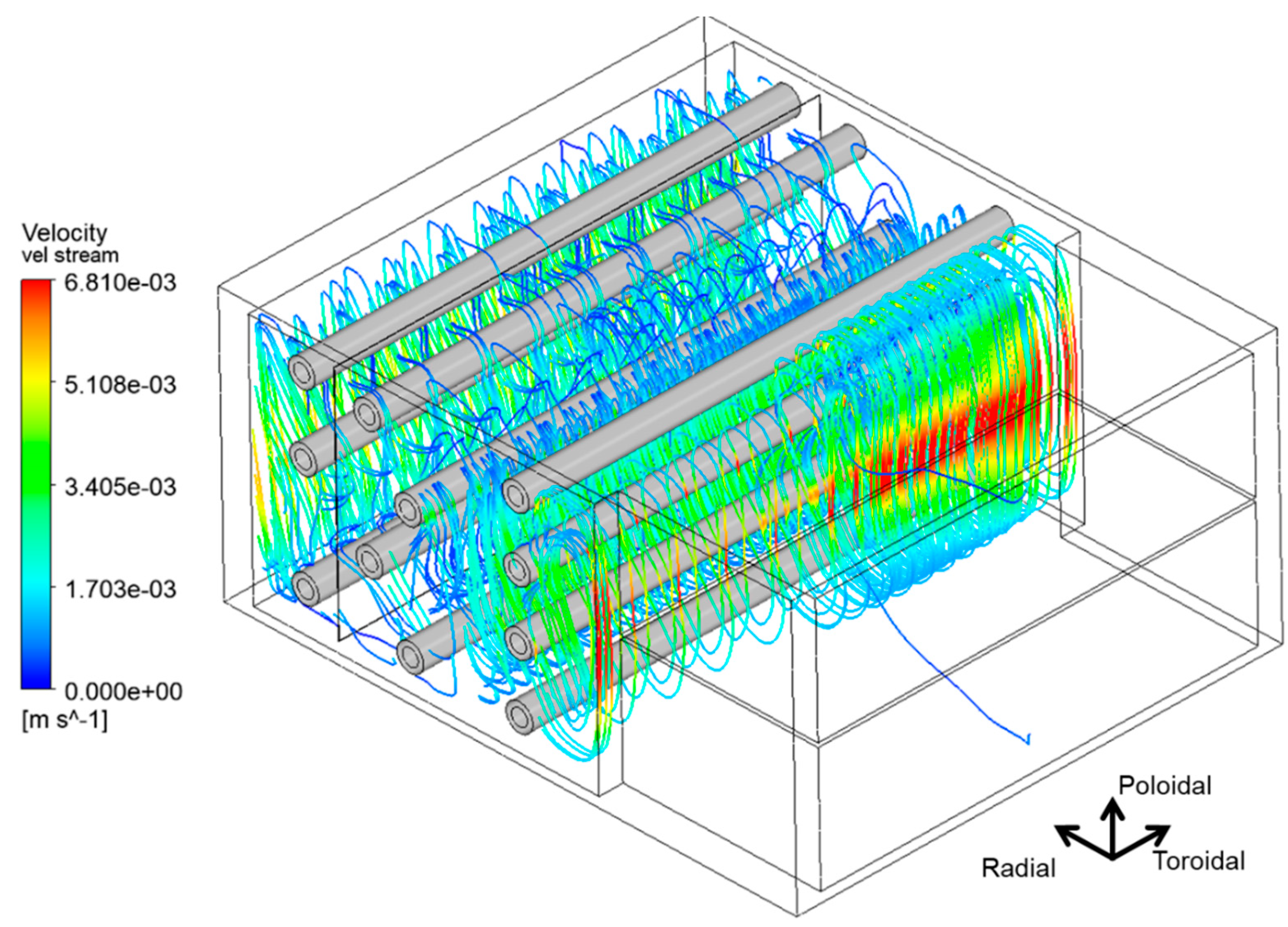
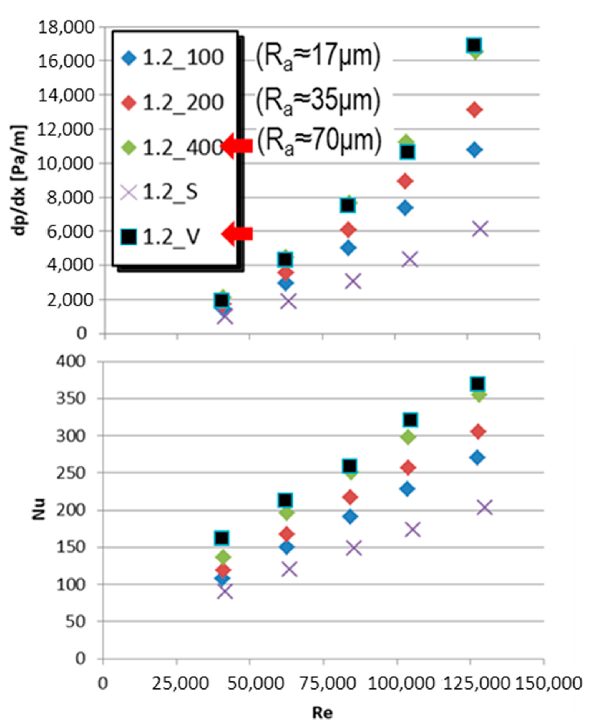
4.3.2. Thermal–Hydraulics

Global simplified FE thermal analyses have been performed for the COB and LIB segments with ANSYS Workbench [60]. These analyses have served not only to confirm the adequacy of the FW design and the BB thermal–hydraulic parameters, but also as input for further global thermo-mechanical analyses. The segments are modeled here without the pins but with the FW, backplates and BSS. The FW coolant is represented by 1D fluid elements, which assumes fully developed and incompressible flow with pure convective heat transfer. The FW receives a BZ heat flux which has been estimated from the LIB and COB thermal–hydraulic slices. The 3D distributions of the charged particles and radiation heat fluxes on the FW [61] have been mapped into the FE model. Thanks to the presence of discrete limiters [62], which shadow the large majority of the FW from charged particles during normal operation. For this reason, the resulting peak heat fluxes are very localized (mostly very small area of the IB upper port region FW with ≈1 MW/m2) and most of the FW heat flux load is of radiative nature (≈0.3 MW/m2). Radial–poloidal distribution of the nuclear heating has been applied to the segment structure and the design mass flows and expected heat transfer coefficients have been defined in the FW cooling channels and at the BSS. The results show that the segment temperature (Figure 23) can be kept at a maximum temperature of around 550 °C and the majority of the segment temperature, including the FW, is kept at a low temperature (300–400 °C).
As stated in Section 4.1, the Δp is a key figure of the HCPB affecting the design of the PHTS. As the first step, global 3D CFD hydraulic analyses have been performed to evaluate the COB Δp. To simplify the global model, the porous media approach has been used to represent the BZ and FW, while the BSS has been represented in full detail. The resulting Δp at the COB is 0.8 bar and a preliminary estimation for the LIB segment results in 0.55 bar. Due to the parallel hydraulic connection of IB and OB segments at the PHTS, the result for the IB evidences a margin for contingency and it is considered at the moment that the total BB Δp is therefore 0.8 bar. The contribution of the segment-inlet-to-FW-path, FW, FW-to-BZ-path, BZ and BZ-to-segment-outlet-path to the Δp are 13%, 48%, 2%, 7% and 30%, respectively. Therefore, the two largest contributors are the FW and the flow path from the BZ to the BSS outlet piping. The later has still a large potential for improvement, while the former is close to its technological limit. However, most of the FW Δp is due to the over-cooling measures taken in very limited regions of the FW where incident-charged particles result in high heat fluxes. If further development with the limiters design allows to shadow the totality of the particle heat flux, the Δp will be significantly reduced.
Local CFD analyses are performed to assess system requirements with respect to material temperature design limits. For this, equatorial slices of the LIB and COB of the HCPB pin design representing periodic poloidal units have been modelled in ANSYS CFX. The thermal loads correspond here to those in normal operation at the end of the flat top. A first run of analyses has been performed assuming a homogeneous mass flow in the pins that produces an outlet temperature of 520 °C. These analyses clearly show that the outlet temperature in each pin is not homogeneous. Especially for the LIB, the pins at the FW side walls are too low (≈460 °C) and too high at the central ones (≈570 °C), which results in an overheating in the EUROFER97 at the BZ backplate region. These analyses revealed that a flow distributor plate or suitable orifices are necessary to adjust the inlet mass flow in the pins to homogenize the outlet temperature in the pins and to avoid over-heating.
A second run of analyses with adjusted mass flows in the pins in order to achieve an outlet temperature of 520 °C in each pin show that the IB and OB temperature in the structural and functional materials (Figure 24-top and bottom, respectively) globally fulfils the design limits. Only very localized peaks at the IB and OB of ≈570 °C (average temperature in the thickness) in the inner tube of the outer pins are observed. Yet, these regions are under a low stress and are not considered to represent a major concern.
CFD transient analysis of the COB has been performed as well in order to determine the coolant response against power excursions due to non-perfect pellet injector success rates [63]. These power excursions have been defined to be +7.5%/−15% from the nominal value for <10 s. Hence, such fluctuation has been defined in the analysis and at the inlet temperature in the BZ (as a worst case, assuming a very small thermal inertia in the FW). It has been observed that the outlet temperature of the BB remains nearly constant, denoting large thermal inertia in the BZ. This characteristic is positive for the PHTS, as it damps the effect of such excursions in the PCS.
Finally, the capability of a He-cooled FW to deal with high heat fluxes of ≈1 MW/m2 has been assessed. The FW channels are thought to be equipped with heat transfer augmentation structures, such as V-ribs (e.g., [64,65,66]). For this, two types of analyses have been performed. First, detailed 1-channel FW CFD studies have been carried out in which prototypical heat flux profiles have been parametrized from 1 MW/m2 to 1.6 MW/m2 and applied on the FW (Figure 25). Here, the Nu and Δp of a channel equipped with V-ribs have been compared to those of a channel equipped with sand-like surface roughness. The goal has been to determine the surface roughness that results in an equivalent cooling capability for a FW with V-ribs. This equivalent sand roughness can be later used in full-scale FW thermal–hydraulic analyses, which otherwise would not be possible with V-ribs due to computational limitations. It has been found that an average roughness Ra ≈ 70 μm at the plasma side of the FW channels can represent an equivalent Nu and Δp behavior as the planned V-ribs (Figure 26). Second, this result has been used later to perform thermal–hydraulic parametric studies on a portion of the IB region FW subjected to high heat flux peaks. The results of this parametric study show that a prototypical heat flux up to a peak of ≈1 MW/m2 of a COB FW channel can be cooled via V-ribs (or an equivalent sand roughness of Ra ≈ 70 μm) with a pressure drop of ≈0.38 bar. A peak of ≈1.2 MW/m2 can be also sustained within the EUROFER97 temperature limits but with a pressure drop of 0.64 bar. The results of this study have been used to benchmark models for heat transfer correlations for high rough surfaces and have been used to configure the FW channel cross section and local heat transfer enhancement needs in the FW, which has been used to assess the global thermal behavior of the BB in the aforementioned global thermal analyses.

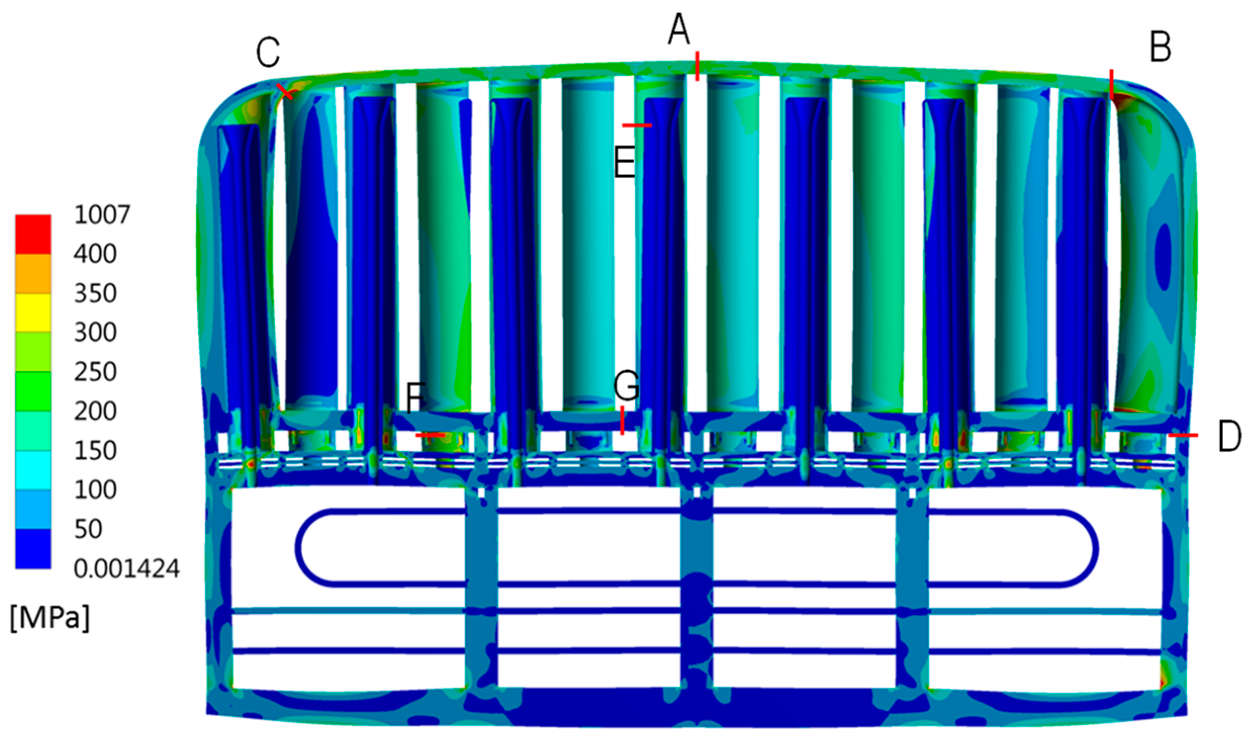
4.3.3. Thermo-Mechanics

The most relevant load combinations on the HCPB have been identified and are listed in Table 1. During the PCD phase, it has been considered that the load cases Cat. I-4, Cat. IV-34 and cases involving disruption events are also the design drivers of HCPB. However, due to the complexity of the analyses involving disruption events, only the VDE-up [67] has been assessed as a representative case (to be defined is the classification of this event as Cat. II-6 or Cat. III-4). Also, thermal–hydraulic analyses have demonstrated the large thermal inertia of the BZ, which is able to dampen small plasma power excursions and therefore Cat. I-5 has been not considered at the moment. No information for seismic loads (SL) has been available during PCDR and therefore those load cases involving SL have not been covered. Similar to the WCLL, the RCC-MRx code has been used to assess the fulfilment of structural criteria.
An overview of the structural behavior of the HCPB “pin” design for the Cat. I-4, Cat. II-6/Cat. III-4 and Cat. IV-34 is provided in the following section.
Cat. I analyses (Normal operation). The fulfilment of structural criteria in the HCPB during normal operation has been assessed in an equatorial unit slice of the COB segment. The NO temperature distribution at the end of the flat top has been imported here and the design pressure of the coolant and purge gas have been applied to the corresponding wetted surfaces. The Von Mises equivalent stress field from the primary and secondary loads is plotted in Figure 27, with indications of the path locations (A to G) for the stress assessment with the RCC-MRx code. It has been observed that the FW fulfils all damage modes, except for the ratcheting and fatigue modes in the B and C locations. This is due to the aggressive transition from the very thick side walls to the thin plasma side of the FW, which results in stress concentrations in these locations. Future designs will have to either smooth this transition or evaluate the possibility of not embedding the pins at the side wall of the FW to reduce the thickness of the FW side wall.
It has been also observed that most of the problematic locations in the BZ are located at the backplate in all damage modes. Future design efforts will be conducted to simplify this region and avoid the connection of the pins to the backplate suffering less bending stresses.
Cat. II/III analyses (VDE-up). Full-scale thermo-mechanical analyses of a complete HCPB DEMO during a VDE-up have been performed. In order to conduct the analyses, the segments have been simplified, in which the solid structures are replaced by shell elements and the pressure tubes are replaced by beam elements. The FW has been modelled as a shell element with orthotropic material properties, which have been defined by comparing stress and modal analyses with a real FW solid model. Thermal (NO) and EM loads ([67]) have been applied to the segments. The thermal loads have been simplified, in which the poloidal distribution of the temperatures has been (conservatively) assumed as constant and only a radial profile has been considered. The analyses are steady state, taking into account the EM loads from two selected time instants of [67] (11.52 s and 11.594 s) which corresponds to the time instants where global resultant forces and moments peak. The weight has been neglected in these analyses. The attachment system has been simplified as well and represented as a series of boundary conditions, including the corresponding gaps to allow for the thermal expansion and stiffness for each support, represented by non-linear springs.
Despite the simplified nature of these analyses, they could provide satisfactory and useful results. Figure 28 shows a representative plot of the equivalent Von Mises stress distribution in the COB segments depending on the applied loads (EM loads for the case after 11.52 s). The model has shown that the stresses are within reasonable values in the majority of the segment, except for regions around the attachment locations, which show artificial stress concentrations due to their simplified nature. Overall, the analyses have shown two key outcomes. First, the stresses derived from EM loads on an SMS architecture are significantly low (well below the (Rp0.2)min (≈360 MPa) of EUROFER97 at 500 °C), confirming the observations for WCLL. Second, when thermal loads are involved, stress peaks of >350 MPa are found in the pressure tubes, the backplate and the connection of the backplate to the side walls of the FW. Future design efforts should be focused on improving the thermal gradients in the BZ, and in particular, on searching a modified flow distribution in which key structural elements of the BB are wetted by the colder parts of the coolant so as to minimize these thermal gradients.
Cat. IV analyses (in-box LOCA). The analyses to assess the code compliance during at in-box LOCA event have been conducted in the same unit slice as for the Cat. I-4 case and in the upper cap region of the COB segment. Here, all internal surfaces of the BZ have been wetted with the coolant at 9.2 MPa (design pressure + a 15% margin) and the temperature distribution at the end of the flat top plasma pulse has been applied. The equivalent Von Mises stress distribution in the slice from the primary loads is shown, together with the paths studied for the stress linearization, in Figure 29. Here, plastic instability and flow localization damage modes have been assessed. While the analyses show nearly full code compliance for the former damage mode, they show problematic regions nearly everywhere for the latter.
During the PCD phase, it has been identified that the immediate plastic flow instability damage mode is overly conservative and may not be fully applicable for EUROFER97 [68]. For this reason, at the end of PCD phase, the application of inelastic design rules, which are anticipated in RCC-MRx but are not yet fully developed for EUROFER97, has been considered. The application of inelastic design rules has been studied for the upper cap region of the COB segment in [69] and compared with the elastic route. Indeed, when comparing results with both routes, the inelastic route shows a general compliance with the design safety criteria, while the elastic route for the same case provides too conservative estimates.

5. Gate Review G1: Challenges and Opportunities

5.1. General BB System Design Challenges

As stated in Section 1, the revised EU DEMO strategy during the PCD phase introduced the stage design approach. The PCD concluded with a final WPBB design review by an external independent panel of experts, which defined exit charges for G1. The review concluded that both driver BB candidates largely fulfilled the main objectives for the PCD phase, but several key issues were identified and recorded in the project risk register [70]. The following are the common risks identified for both the BB concepts:
  • Low reliability of the BB system;
  • Low readiness level of manufacturing technologies for BB segments and associated high costs;
  • Reduction in the structural integrity of BB during shutdown due to the EUROFER97 ductile-to-brittle transition temperature (DBTT) shift during irradiation;
  • Large tritium permeation rates at the BZ–coolant interface;
  • Low reliability of tritium transport analyses;
  • Supply chain and high cost of Li-6 enrichment;
  • High EM loads due to disruption events;
  • No readily available process for manufacturing functionally graded W coatings for the FW;
  • Low readiness of the codes and standards to design DEMO IVC;
  • Over-pressurization (OP) or in-box LOCA scenario—Level D in RCC-MRx (Cat. IV loads).
Most of these risks are related to R&D and the WPBB project execution plan for the CD phase has defined specific activities to address these technology risks. A key design issue of both designs is their inherent complexity, originating from the nature of their architecture due to the separation of the high-pressure coolant from the low-pressure BZ together with the need for a large interface surface to guarantee the correct heat transfer between both. This translates into a large number of welded joints, Nw (105 < Nw < 106), preventing an in-box LOCA event, which has been demonstrated to result in a very low reliability of the BB system [71]. Specific design efforts for each of the concepts will be conducted during the CD phase to mitigate this issue. For the same reason (the very large interface BZ–coolant contact surface), the tritium permeation rates into the coolant is an issue for both concepts, which may be approached by design. Also, both designs require 6Li to achieve the required TBR. Given that natural Li only contains 7.6% of 6Li, the isotopic separation is difficult and thus costly. A recent study comparing different methods [72] concluded that the column exchange (COLEX) separation method is the preferred one, taking into account during comparison, among others, the maturity, industrialization potential and costs.
The concept specific design challenges identified for each of the driver candidate designs are summarized in the following.

5.2. Specific WCLL System Design Challenges

During the PCD phase particular attention has been paid to R&D on the PbLi–water interaction. Indeed, in the case of a coolant leak within the breeder, exothermic reactions between Li and water, generating hydrogen, will take place, posing serious safety concerns in BB. Several numerical and experimental activities have been performed at ENEA Brasimone research center [73,74], where experimental tests under relevant working conditions were carried out. These activities allowed also to increase the modeling capabilities by coupling different codes (e.g., SIMMER-RELAP5 coupling [75]). R&D on PbLi–water interaction during the CD phase is being continued with the aim of performing experiments with representative mock-ups in relevant operating conditions [76].
Contrarily to the HCPB, a key technological issue due to the choice of the functional material in this design is related with the tritium extraction efficiency of the TEU with PbLi. Three technologies have been identified for this purpose: the permeator against vacuum (PAV), the gas–liquid contactor (GLC) and the liquid vacuum contactor (LVC). All three present advantages and disadvantages, of which the LVC is the least mature. In the PAV process, tritium is extracted from PbLi by permeating against vacuum through a membrane, thus resulting in pure tritium directly transferable to the tritium plant, while the tritium extracted from GLC in a molecular form of mixed gas with helium, thus requiring an additional step of tritium removal from this mixed gas. Thus, PAV is considered simpler than GLC. However, the uncertainties related to the tritium transport through the membrane are large and the pumping requirements to achieve a reasonable high tritium extraction performance are also high. On the other hand, a TEU based on GLC technology is simpler to manufacture and based on widely used industrial processes but difficult to operate. Prototypes of all technologies are being constructed and are to be tested during FP9 to validate their performance predictions and support the selection of the most promising for DEMO. A more detailed description of the technologies, th issues and plans are given in [77].
Concerning neutronic performances, WCLL BB concept is “hystorically” characterized by very good shielding performances counterbalanced by low tritium breeding. A considerable effort has been made during the PCD phase in order to enhance this figure of merit. Indeed, despite the reduction in the BB radial dimension, a TBR of 1.15 was reached, fulfilling the requirement on the required target TBR (≥1.15), while maintaining excellent shielding performances. The small TBR reduction assessed from the last neutronic analyses will be faced during the CD phase by reviewing the BB design. In particular, a novel DWT layout is under assessment [36]. This new geometry envisages a significant reduction in the number of DWTs, whilst simultaneously tackling the risks on neutronic performances and BB reliability.
Another concern related to the modeling capability is related to MHD and its influence on PbLi thermal–hydraulic behavior. Also, in this case, an intense R&D campaign has been carried out during the PDC phase. From the experimental point of view, different test were carried out at KIT and will be performed in the future, especially after the relocation of the MaPLE facility at KIT [78]. From the modeling point of view, benchmarking activities are currently in progress to set-up of new codes which can reproduce the complex multi-physical phenomena occurring in the BB environment.
The WCLL BB remote maintenance takes into account the possible PbLi and water draining before starting the operations. It is therefore important to evaluate if an efficient fluid drainage is possible. For this purpose, a dedicated activity is being carried out. The study models the PbLi and water draining in different scenarios, such as the adoption of the feeding pipes for the draining procedure or the use of additional dedicated draining pipes. Concerning the PbLi breeder, the uncertainty of helium production and accumulation as a result of transmutation processes poses an additional warning, since it may significantly influence the draining process. For this purpose, a dedicated R&D campaign is currently ongoing [26].
Finally, the construction and running of the water loop facility [79] at ENEA Brasimone research center and CHIMERA facility at CCFE [80] will allow to perform experimental tests on prototypical mock-up of WCLL BB key components, as the FW, the BZ and the manifold, in relevant operating conditions, both in terms of temperature and pressure and, in case of CHIMERA, magnetic field as well.

5.3. Specific HCPB System Design Challenges

An important achievement in the PCD phase during the WPBB final review has been the timely identification of the critical issues on the tritium retention in Be and the mass production problems of TiBe12 pebble beds. However, the proposal of TiBe12 in the form of prismatic blocks is technically immature at the moment, as little is known about the thermo-mechanical behavior of such blocks under thermal cycling, which is to be investigated extensively during the CD phase.
Although significant progress has also been achieved in reducing the HCPB system pressure drops, the resulting circulating power is still considered moderate and a very low margin is left, which can jeopardize the PHT’s maturity and plant architecture layout.
The HCPB concept has been demonstrated to be efficient for tritium breeding due to its low neutron parasitic absorption and low neutron attenuation in the BZ. However, this very feature makes it, at the same time, inefficient for neutron shielding, meeting the criteria only marginally. The first scoping analyses have identified proposals to enhance the shielding during the PCD phase [57]. However, the most promising designs will have to be maturated during the CD phase.
The very nature of the HCPB using solid functional materials requires industrial production routes. The TRL of the manufacturing technologies for the TiBe12 blocks and ACB pebbles is considered low at the end of the PCD phase. Apart from specific R&D to increase this TRL, design measures will be aimed to ease achieving higher TRL for manufacturing and/or assembly. Also, the lack of irradiation data for these materials, necessary for design analyses, will have to be bridged by specific irradiation campaigns during the CD phase.
Despite the significant advances during the PCD phase [81], the current methods for thermo-mechanical modeling of pebble beds have limited scalability, requiring very large computational resources for larger pebble bed assemblies. Thus, an integral and simplified approach is needed for practical use in BB assessments.
As for the TER, the present reference is based on a well-established cryogenic industrial process, working in batch modus from adsorption to regeneration. The only drawback of this technology is the N2 and power consumption, but for a low-pressure purge gas setting, these are within reasonable values. However, as it will be explained in Section 5.5, working at a high-pressure purge gas may be desirable for reliability reasons. In this case, the N2 consumption would be prohibitive and the use of getter beds instead of CMSB would be required. Non-evaporable getters (NEG) in the form of ZAO alloy (Ti-Zr-V-Al) discs have been selected as the technology for the getter beds and a prototype will be tested during FP9 to validate its performance and confirm its validity for DEMO. A more detailed summary description is given in [77].

5.4. BBS Integration Challenges

Some technical features of the BB System (e.g., the type of coolant and breeder, and the technology used for tritium extraction/control and coolant purification) impact not only the BB design but also the interfacing systems and as a consequence, of the overall tokamak layout. For these reasons, the design of such integrated systems cannot be made in isolation without taking into account the strong interactions, and therefore the implications on the plan architecture.
Therefore, the use of a holistic design/integration approach became mandatory in order to verify that the architectures being developed are consistent and the major issues are addressed and tackled as well as to calibrate the BB ancillary systems operating parameters and the selection of suitable technologies [82].
In particular, three main design and integration cross fields have been so far identified and studied: (i) radiation protection in the blanket and ancillary systems, (ii) definition of the tritium management systems working points in terms of extraction, inventories and releases [83] and (iii) RM of the BB [84].
Thus, possible solutions for improving the shielding capabilities of HCPB have been investigated [85], as well as the impact of water coolant activation (i.e., the spatial distribution of 16N and 17N isotopes dose rates [86]) on the WCLL BB, in particular, in proximity of isolation valves [87].
Furthermore, the reference and back-up technologies used in the tritium extraction and removal (TER) for the helium purge gas and the PbLi have been developed addressing the key feasibility aspects and the implications on the tokamak layout. Considerable R&D activities have been carried out to support the technology selection (e.g., tritium permeation barriers [88]). As the BB internals offer an ideal environment (e.g., thin structural material with high temperatures) to promote tritium permeation, studies have been carried out to establish a tritium balance in the different systems during operation, with special care to the permeation rate and inventory in the coolant. Those are the key parameters for the feasibility assessment and technology selection for the coolant purification systems (CPS).
Moreover, the control of tritium concentrations and inventories in the entire chain of systems has been pursued to avoid (i) non-tolerable tritium permeation into the BB coolant (from the breeding units as well as from the plasma chamber into the FW channels [89]), and (ii) non-tolerable T-losses from the primary circuit (a) into the building and (b) through the heat exchangers into the secondary loop and hence to the environment. Further development area has been identified for the minimization of the tritium releases using permeation barriers and guard pipes on both the TER systems as well as to increase the performances of the CPS and TER in terms of mass flow rates and efficiencies. More details can be found in [82].
Conclusively, strong efforts have been also dedicated to the design and feasibility of BB vertical segment-based architecture. Several studies, assuming a full banana segment or a split BB as well as performing the maintenance of the blanket from the upper and/or lower ports, have been performed. The findings of this study, summarized in [84], have demonstrated that the current space inside the VV and the ports available for remote maintenance operations are too constrained. This means that no viable solutions can be found within these boundary conditions and thus some compromises on the port size are needed in the future.

5.5. Opportunities

As indicated in Section 5.1, reliability has been identified as an important issue for the BB system. Other authors also highlight the key importance of reliability in the success of nuclear fusion and opine that it should be given the highest priority in the design of in-vessel components [90]. Indeed, designing a blanket for high reliability is a very difficult challenge to solve due to the very nature of the BB system as an in-vessel system. This is because as an in-vessel system, the BB requires to be split into some elements, at least equal to the number of sectors. If the BB maintenance strategy is vertical, as it is for the current EU DEMO, an additional splitting between IB and OB elements into further segments is necessary, so that they are thin and light enough to be handled and can fit through the upper or lower ports. If the BB system can be regarded as the equivalent of a reactor vessel core in a fission reactor, the analogous situation in fission would be having a main vessel where many smaller vessel cores are introduced and each are fed with their feeding pipework. The tokamak architecture imposes two additional difficulties on the BB system. First, it is the fact that it is placed inside a vessel (the VV) that has a toroidal shape, which reduces the chances of using largely simpler and conventional manufacturing technologies. Second, it is the very large size of the tokamak itself, which means that more sub-components are needed in the BZ to fill the large resulting volumes of the BB elements. Clearly, further splitting of the BB elements into smaller modules, as in ITER rapidly, multiplies the number of feeding pipes per module, necessarily reducing the reliability to unfeasible levels, as already identified during the PPCS studies [91].
A comprehensive reliability study in [71] has identified that the large number of welds acting against an in-box LOCA is a major driver for BB reliability. Given that both blankets have a similar number of such welds (~4·105), both BBs show the same order of magnitude of a few events per year initiated by the failure of the BB leading to a plant shutdown.
The relatively high number of BZ welds acting against an in-box LOCA is not only the result of the large size of the BB segments, but also of the internal arrangement of BZ structures (or units), constructed along the radial direction and periodically repeated in the poloidal dimension. While this radial arrangement of sub-components has been found to be efficient for tritium breeding and is easy to manufacture (due to the relatively small radial dimension of these sub-components), it results in a large number of sub-components in the internal BZ welds. Changing the BZ structures from radial to poloidal will result in larger but fewer structures and less welded joints.
Some design investigations on poloidal arrangements were started during the PCD phase for the WCLL [92,93], but further work is being conducted in this direction to develop an innovative solution that simplify the internals while meeting all other BB functional and safety requirements.
While the poloidal arrangement of the cooling structures is an option for the WCLL due to the low temperature difference in the water coolant through the BZ, its implementation in the HCPB is more difficult due to the larger coolant temperature window. However, the fact that the coolant and the purge gas fluids are essentially the same (helium), brings a key opportunity to improve the reliability of this BB design by equalizing the pressure of the purge gas chambers to that of the coolant inside the BB. In this way, an in-box LOCA does not exist, removing this major initiating event from the failure rate, thus increasing the reliability by bringing in this fault-tolerant feature. Only local by-passes might occur in case of a failure of an internal weld, leading to a function deterioration with the time, but not to a plant shutdown. The drawback of this solution is that the HCPB should be redesigned to withstand a high pressure purge gas at normal operation, which requires a design effort to improve the TBR in order to offset the foreseeable increase in structural material to reinforce the BB. Additionally, the TER system should be redesigned as well to withstand a high pressure purge gas. It has been already identified that the CMSB part of the TER should be substituted by getter beds, as the consumption of liquid N would be otherwise prohibitive. But first, industrial feedback does not reveal major issues with the proposal.
Regarding the tritium permeation issue, the WCLL relies on anti-permeation coatings to reduce the permeation rate by orders of magnitude. However, from a design standpoint, the same opportunity for the reliability issue arises from the fact that a poloidal configuration of cooling tubes in the WCLL would substantially reduce the surface area between the breeder and coolant interface and thus the permeation rate. Therefore, this aspect will be also studied at the same time that an innovative solution in a poloidal arrangement will be developed for WCLL to mitigate the reliability issue. For the HCPB, the addition of steam in the purge gas and H2 in the coolant has been demonstrated to reduce the permeation rate by a factor of five [82]. Therefore, studies will be continued in this direction to set the appropriate purge gas and coolant chemistry parameters in the CD phase to mitigate the tritium permeation problem in the HCPB.
A review of the options of tritium breeder and neutron multiplier functional materials in [94] towards the end of the PCD phase led to the proposal of a new family of breeding blanket concepts based on separated tritium breeder ceramics and Pb or Pb alloys as neutron multiplier. This proposal was specially addressed for the HCPB to mitigate by design the issues associated with the use of Be/Be alloys. Here, the TiBe12 prismatic blocks around the fuel pins are replaced by simply filling the pins interspaces with molten Pb, thus the helium-cooled molten lead and ceramic breeder (MLCB, or HLCB) concept. Preliminary analyses have shown that neutronic, thermal–hydraulic and thermo-mechanical requirements can be met with only minor modifications of the current HCPB design [95,96].
The idea of using ceramic tritium breeder and molten lead can be also extended to a water-cooled concept, namely the water-cooled lead and ceramic breeder concept (WLCB). Indeed, the use of these functional materials offers an interesting trade-off opportunity between WCLL and HCPB. On one hand, the use of PWR water technology in the WCLL profits from the existing multi-year industrial experience for the PHTS and the balance of plant (BoP). On the other hand, the use of ITER-like proven tritium extraction technology in the HCPB profits from a ceramic breeder pebble bed with a purge gas. This concept can potentially mitigate several design and technology issues of the present WCLL, like the technology issue of the tritium extraction from PbLi, the need for using anti-permeation coatings and the water–PbLi reactivity. Some preliminary studies assuming the same architecture as the HCPB have been performed for the WLCB showing its potentiality [97,98]. However, the WLCB will be revised during the CD phase to implement a poloidal architecture and a comprehensive design development and analyses campaigns will be carried out to verify that current BB requirements for a driver BB are met.
Regarding the issues associated with helium cooling technology, some research has been already conducted during the PCD phase using CO2 as a high-temperature gas coolant variant. CO2 is thought to be the only practical alternative due to its availability, cost, neutron economy and relative chemical inertness, as well as the large industrial experience collected from MAGNOX and AGR reactors [99]. Studies during the PCD phase have revealed that a similar neutronic, thermal–hydraulic and structural performance like the HCPB can be reached using a CO2-cooled BB with a HCPB-like architecture [100,101]. Although the use of CO2 could be justified from a design standpoint, some factors remain unknown regarding its use as a coolant in a fusion environment: (1) the behavior of CO2 under fusion neutron spectrum and in particular the potential radiolysis of CO2, (2) the effect of radiolysis products in the structural material at high temperatures and (3) the interaction of permeated tritium into CO2 coolant with the presence of radiolytic products, potentially forming other compounds like H2O and CH4 and their effect in the coolant purification system and the TER. No further work yet has been envisaged in this respect during the CD phase, but if these technology gaps can be bridged by appropriate R&D, CO2 coolant can be an attractive, cost-effective option for a high-temperature (~600 °C) gas-cooled BB.
A comprehensive R&D program has been presented in the project execution plan of the WPBB at G1. This aims at addressing all the risks identified in the project risk register [70], especially covering those items which cannot be dealt just by advancing the design, e.g., testing prototypical mock-ups under relevant functional conditions, developing anti-permeation coatings, developing fabrication technologies for functional materials and their upscale to DEMO, material characterization after irradiation, developing structural material, codes and standards, etc. Further details on R&D and technology development can be found in [77].

6. Summary and Outlook towards the CD Phase

The PCD phase concluded with a successful final design review at G1 of the different WPs in the DEMO project, including the WPBB. During G1, a first set of comprehensive documentation following a systems engineering format has been produced, conforming the baseline documentation for the two candidate driver BBs considered for DEMO, the WCLL and the HCPB. G1 acknowledged the achievements but highlighted the challenges ahead and project risks, which has constituted the basis for drafting the project execution plan for the consequent CD phase starting after G1.
The CD phase will be formed by two well differentiated sub-phases, separated by a G2, in which the first will be devoted to the concept selection of key design and technology solutions for each of the main DEMO systems, while the second aims at validating the concept selection in G2 to consolidate an integrated system concept design that will conclude with a G3 [102]. In particular, a main goal of the CD phase is to demonstrate the feasibility of the proposed conceptual designs and downselect among them. System designers will continue working on the existing design variants to mitigate the identified risks whenever possible and may propose new variants to the baseline, if they prove to offer a potential solution or at least mitigate risks. R&D will continue to develop the required technology and to close the existing gaps and offer solutions to risks, where they cannot be covered by design. Both design and technology “legs” of the project will have to remain in continuous feedback loop, so that the proposed designs take into account the readiness of the technological choices involved in them to keep a realistic schedule while R&D provides the project with new or improved technologies driven by plant design. Systematic implementation of system and integration readiness assessments (SRA, IRA), together with technology readiness assessments (TRA) will periodically help to evaluate the maturity of the system designs and its corresponding technology implementation towards demonstrating the feasibility of the proposed conceptual designs.

Author Contributions

Conceptualization, L.V.B., F.A.H., A.D.N., I.C. and M.U.; formal analysis, F.A.H., A.D.N., P.A., I.C., M.U., G.A.S. and G.Z.; investigation, F.A.H., A.D.N., P.A., I.C., M.U., G.A.S. and G.Z.; writing—original draft preparation, F.A.H., P.A., P.S., I.C., A.V. and G.A.S.; writing—review and editing, A.D.N., L.V.B., G.Z. and M.U.; visualization, F.A.H., P.A., I.C., G.A.S., A.V. and G.Z.; supervision, L.V.B.; project administration, L.V.B.; funding acquisition, L.V.B. All authors have read and agreed to the published version of the manuscript.

Funding

This work has been carried out within the framework of the EUROfusion Consortium, funded by the European Union via the Euratom Research and Training Programme (Grant Agreement No 101052200—EUROfusion). Views and opinions expressed are however those of the author(s) only and do not necessarily reflect those of the European Union or the European Commission. Neither the European Union nor the European Commission can be held responsible for them.

Data Availability Statement

Not applicable.

Conflicts of Interest

The authors declare no conflict of interest. The funders had no role in the design of the study; in the collection, analyses, or interpretation of data; in the writing of the manuscript; or in the decision to publish the results.

References

  1. Boccaccini, L.V.; Aiello, G.; Aubert, J.; Bachmann, C.; Barrett, T.; Del Nevo, A.; Demange, D.; Forest, L.; Hernandez, F.; Norajitra, P.; et al. Objectives and status of EUROfusion DEMO blanket studies. Fusion Eng. Des. 2016, 109–111, 119–1206. [Google Scholar] [CrossRef]
  2. Romanelli, F.; Barabaschi, P.; Borba, D.; Federici, G.; Horton, L.; Neu, R.; Stork, D.; Zohm, H. Fusion Electricity—A Roadmap to the Realisation of Fusion Energy; EFDA: Culham, UK, 2012. [Google Scholar]
  3. Donné, A.J.H. European Research Roadmap to the Realisation of Fusion Energy; EFDA: Culham, UK, 2018. [Google Scholar]
  4. Federici, G.; Boccaccini, L.; Cismondi, F.; Gasparotto, M.; Poitevin, Y.; Ricapito, I. An overview of the EU breeding blanket design strategy as an integral part of the DEMO design effort. Fusion Eng. Des. 2019, 141, 30–42. [Google Scholar] [CrossRef]
  5. Federici, G.; Bachmann, C.; Barucca, L.; Baylard, C.; Biel, W.; Boccaccini, L.V.; Bustreo, C.; Ciattaglia, S.; Cismondi, F.; Corato, V.; et al. Overview of the DEMO staged design approach in Europe. Nucl. Fusion 2019, 59, 066013. [Google Scholar] [CrossRef] [Green Version]
  6. Federici, G.; Holden, J.; Baylard, C.; Beaumont, A. The EU DEMO staged design approach in the Pre-Concept Design Phase. Fusion Eng. Des. 2020, 173, 112959. [Google Scholar] [CrossRef]
  7. Federici, G.; Bachmann, C.; Barucca, L.; Biel, W.; Boccaccini, L.; Brown, R.; Bustreo, C.; Ciattaglia, S.; Cismondi, F.; Coleman, M.; et al. DEMO design activity in Europe: Progress and updates. Fusion Eng. Des. 2018, 136, 729–741. [Google Scholar] [CrossRef]
  8. Bachmann, C.; Gliss, C.; Härtl, T.; Hernandez, F.; Maione, I.; Steinbacher, T.; Vizvary, Z. Mechanical support concept of the DEMO breeding blanket. Fusion Eng. Des. 2021, 173, 112840. [Google Scholar] [CrossRef]
  9. Fischer, U.; Boccaccini, L.; Cismondi, F.; Coleman, M.; Day, C.; Hörstensmeyer, Y.; Moro, F.; Pereslavtsev, P. Required, achievable and target TBR for the European DEMO. Fusion Eng. Des. 2020, 155, 111553. [Google Scholar] [CrossRef]
  10. Stork, D.; Agostini, P.; Boutard, J.; Buckthorpe, D.; Diegele, E.; Dudarev, S.; English, C.; Federici, G.; Gilbert, M.; Gonzalez, S.; et al. Developing structural, high-heat flux and plasma facing materials for a near-term DEMO fusion power plant: The EU assessment. J. Nucl. Mater. 2014, 455, 277–291. [Google Scholar] [CrossRef] [Green Version]
  11. Maviglia, F.; Bachmann, C.; Federici, G.; Franke, T.; Siccinio, M.; Albanese, R.; Ambrosino, R.; Arter, W.; Bonifetto, R.; Calabrò, G.; et al. Integrated design strategy for EU_DEMO first wall protection from plasma transients. Fusion Eng. Des. 2022, 177, 113067. [Google Scholar] [CrossRef]
  12. Maione, I.A. BB System Requirements Document (SRD) for the Definition Dossier; IDM Report EFDA_D_2PAZCH; EUROfusion: Garching, Germany, 2020. [Google Scholar]
  13. Spagnuolo, G.A.; Bongiovì, G.; Franza, F.; Maione, I.A. Systems Engineering approach in support to the breeding blanket design. Fusion Eng. Des. 2019, 146, 31–35. [Google Scholar] [CrossRef] [Green Version]
  14. Arena, P.; Del Nevo, A.; Moro, F.; Noce, S.; Mozzillo, R.; Imbriani, V.; Giannetti, F.; Edemetti, F.; Froio, A.; Savoldi, L.; et al. The DEMO Water-Cooled Lead–Lithium Breeding Blanket: Design Status at the End of the Pre-Conceptual Design Phase. Appl. Sci. 2021, 11, 11592. [Google Scholar] [CrossRef]
  15. Del Nevo, A.; Martelli, E.; Agostini, P.; Arena, P.; Bongiovì, G.; Caruso, G.; Di Gironimo, G.; Di Maio, P.; Eboli, M.; Giammusso, R.; et al. WCLL breeding blanket design and integration for DEMO 2015: Status and perspectives. Fusion Eng. Des. 2017, 124, 682–686. [Google Scholar] [CrossRef]
  16. Martelli, E.; Del Nevo, A.; Arena, P.; Bongiovì, G.; Caruso, G.; Di Maio, P.A.; Eboli, M.; Mariano, G.; Marinari, R.; Moro, F.; et al. Advancements in DEMO WCLL breeding blanket design and integration. Int. J. Energy Res. 2018, 42, 27–52. [Google Scholar] [CrossRef] [Green Version]
  17. Tassone, A.; Del Nevo, A.; Arena, P.; Bongiovi, G.; Caruso, G.; di Maio, P.A.; di Gironimo, G.; Eboli, M.; Forgione, N.; Forte, R.; et al. Recent Progress in the WCLL Breeding Blanket Design for the DEMO Fusion Reactor. IEEE Trans. Plasma Sci. 2018, 46, 1446–1457. [Google Scholar] [CrossRef]
  18. Del Nevo, A.; Arena, P.; Caruso, G.; Chiovaro, P.; Di Maio, P.; Eboli, M.; Edemetti, F.; Forgione, N.; Forte, R.; Froio, A.; et al. Recent progress in developing a feasible and integrated conceptual design of the WCLL BB in EUROfusion project. Fusion Eng. Des. 2019, 146, 1805–1809. [Google Scholar] [CrossRef] [Green Version]
  19. Aubert, J.; Aiello, G.; Jonquères, N.; Puma, A.L.; Morin, A.; Rampal, G. Development of the water cooled lithium lead blanket for DEMO. Fusion Eng. Des. 2014, 89, 1386–1391. [Google Scholar] [CrossRef]
  20. Ciurluini, C.; Vannoni, A.; Del Moro, T.; Lorusso, P.; Tincani, A.; Del Nevo, A.; Barucca, L.; Giannetti, F. Thermal-hydraulic assessment of Once-Through Steam Generators for EU-DEMO WCLL Breeding Blanket primary cooling system application. In Proceedings of the 32nd Symposium on Fusion Technology, Dubrovnik, Croatia, 18–23 September 2022. [Google Scholar]
  21. Vannoni, A.; Lorusso, P.; Eboli, M.; Giannetti, F.; Ciurluini, C.; Tincani, A.; Marinari, R.; Tarallo, A.; Del Nevo, A. Development of a steam generator mock-up for EU DEMO fusion reactor: Conceptual design and code assessment. In Proceedings of the 32nd Symposium on Fusion Technology, Dubrovnik, Croatia, 18–23 September 2022. [Google Scholar]
  22. Di Maio, P.A.; Arena, P.; Bongiovì, G.; Catanzaro, I.; Del Nevo, A.; Forte, R. On the effect of stiffening plates configuration on the DEMO Water Cooled Lithium Lead Breeding Blanket module thermo-mechanical behaviour. Fusion Eng. Des. 2019, 146, 2247–2250. [Google Scholar] [CrossRef]
  23. Edemetti, F.; Di Piazza, I.; Del Nevo, A.; Caruso, G. Thermal-hydraulic analysis of the DEMO WCLL elementary cell: BZ tubes layout optimization. Fusion Eng. Des. 2020, 160, 111956. [Google Scholar] [CrossRef]
  24. Mozzillo, R.; Utili, M.; Venturini, A.; Tincani, A.; Gliss, C. Integration of LiPb loops for WCLL BB of European DEMO. Fusion Eng. Des. 2021, 167, 112379. [Google Scholar] [CrossRef]
  25. Tarantino, M.; Angiolini, M.; Bassini, S.; Cataldo, S.; Ciantelli, C.; Cristalli, C.; Del Nevo, A.; Di Piazza, I.; Diamanti, D.; Eboli, M.; et al. Overview on lead-cooled fast reactor design and related technologies development in ENEA. Energies 2021, 14, 5157. [Google Scholar] [CrossRef]
  26. Sedano, L.; Esteban, G.; Cavaro, M.; Iraola, E.; Abdulrahman, A.; Batet, L.; Guasch, M. The solubility of helium in lead–lithium eutectic alloy. Nucl. Mater. Energy 2022, 31, 101185. [Google Scholar] [CrossRef]
  27. Bonifetto, R.; Utili, M.; Valerio, D.; Zanino, R. Conceptual design of a PAV-based tritium extractor for the WCLL breeding blanket of the EU DEMO: Effects of surface-limited vs. diffusion-limited modeling. Fusion Eng. Des. 2021, 167, 112363. [Google Scholar] [CrossRef]
  28. Garcinuño, B.; Rapisarda, D.; Fernández-Berceruelo, I.; Jiménez-Rey, D.; Sanz, J.; Moreno, C.; Palermo, I.; Ibarra, Á. Design and fabrication of a Permeator Against Vacuum prototype for small scale testing at Lead-Lithium facility. Fusion Eng. Des. 2017, 124, 871–875. [Google Scholar] [CrossRef]
  29. Papa, F.; Utili, M.; Venturini, A.; Caruso, G.; Savoldi, L.; Bonifetto, R.; Valerio, D.; Allio, A.; Collaku, A.; Tarantino, M. Engineering design of a Permeator Against Vacuum mock-up with niobium membrane. Fusion Eng. Des. 2021, 166, 112313. [Google Scholar] [CrossRef]
  30. Utili, M.; Alberghi, C.; Candido, L.; Papa, F.; Tarantino, M.; Venturini, A. TRIEX-II: An experimental facility for the characterization of the tritium extraction unit of the WCLL blanket of ITER and DEMO fusion reactors. Nucl. Fusion 2022, 62, 066036. [Google Scholar] [CrossRef]
  31. Garcinuño, B.; Rapisarda, D.; Fernández-Berceruelo, I.; Carella, E.; Sanz, J. The CIEMAT LiPb Loop Permeation Experiment. Fusion Eng. Des. 2019, 146, 1228–1232. [Google Scholar] [CrossRef]
  32. Alberghi, C.; Candido, L.; Utili, M.; Zucchetti, M. Development of new analytical tools for tritium transport modelling. Fusion Eng. Des. 2022, 177, 113083. [Google Scholar] [CrossRef]
  33. Candido, L.; Alberghi, C.; Antonelli, A.; Bassini, S.; Piccioni, M.; Storai, S.; Testoni, R.; Utili, M.; Zucchetti, M. HyPer-QuarCh II: A laboratory-scale device for hydrogen isotopes permeation experiments. Fusion Eng. Des. 2021, 172, 112920. [Google Scholar] [CrossRef]
  34. Malo, M.; Garcinuño, B.; Rapisarda, D. Experimental refutation of the deuterium permeability in vanadium, niobium and tantalum. Fusion Eng. Des. 2019, 146, 224–227. [Google Scholar] [CrossRef]
  35. Moro, F.; Arena, P.; Catanzaro, I.; Colangeli, A.; Del Nevo, A.; Flammini, D.; Fonnesu, N.; Forte, R.; Imbriani, V.; Mariano, G.; et al. Nuclear performances of the water-cooled lithium lead DEMO reactor: Neutronic analysis on a fully heterogeneous model. Fusion Eng. Des. 2021, 168, 112514. [Google Scholar] [CrossRef]
  36. Arena, P.; Bongiovì, G.; Catanzaro, I.; Ciurluini, C.; Collaku, A.; Del Nevo, A.; Di Maio, P.A.; D’onorio, M.; Giannetti, F.; Imbriani, V.; et al. Design and integration of the EU-DEMO Water-Cooled Lead Lithium Breeding Blanket. In Proceedings of the 32nd Symposium on Fusion Technology, Dubrovnik, Croatia, 18–23 September 2022. [Google Scholar]
  37. X-5 Monte Carlo Team. MCNP—A General Monte Carlo N-particle Transport Code—Overview and Theory (Version 5, Vol. I), Los Alamos National Laboratory. Available online: https://mcnp.lanl.gov/pdf_files/TechReport_2000_LANL_LA-13709-M_Briesmeisterothers.pdf (accessed on 30 July 2022).
  38. JEFF3.3 Nuclear Data Library. Available online: http://www.oecd-nea.org/dbdata/jeff/jeff33/#neutron (accessed on 30 July 2022).
  39. Catanzaro, I.; Bongiovì, G.; Di Maio, P.A. Analysis of the Thermo-Mechanical Behaviour of the EU DEMO Water-Cooled Lithium Lead Central Outboard Blanket Segment under an Optimized Thermal Field. Appl. Sci. 2022, 12, 1356. [Google Scholar] [CrossRef]
  40. Allio, A.; Arena, P.; Del Nevo, A.; Savoldi, L. Hybrid modelling for the manifolds and coolant flow distribution in the Water-Cooled Lead-Lithium of the EU-DEMO reactor. In Proceedings of the 19th International Topical Meeting on Nuclear Reactor Thermal Hydraulics (NURETH-19), Brussels, Belgium, 6–11 March 2022. [Google Scholar]
  41. Siriano, S.; Tassone, A.; Carusso, G.; Del Nevo, A. Electromagnetic coupling phenomena in co-axial rectangular channels. Fusion Eng. Des. 2020, 160, 111854. [Google Scholar] [CrossRef]
  42. Roca Urgorri, F.; Fernández-Bercerualo, I.; Rapisarda, D. Magneto-convective analyses of the PbLi flow for the EU-WCLL fusion breeding blanket. Energies 2021, 14, 6192. [Google Scholar] [CrossRef]
  43. Yan, Y.; Ying, A.; Abdou, M. Numerical study of magneto-convection flows in a complex prototypical liquid-metal fusion blanket geometry. Fusion Eng. Des. 2020, 159, 111688. [Google Scholar]
  44. Siriano, S. Numerical analysis of extreme magneto-convective phenomena in the WCLL blanket. In Proceedings of the 32nd Symposium on Fusion Technology, Dubrovnik, Croatia, 18–23 September 2022. [Google Scholar]
  45. Tassone, A.; Carusso, G.; Del Nevo, A. Influence of PbLi hydraulic path and integration layout on MHD pressure losses. Fusion Eng. Des. 2020, 155, 111517. [Google Scholar] [CrossRef]
  46. Design and Construction Rules for Mechanical Components of Nuclear Installations (RCC-MRx); AFCEN: Paris, France, 2012.
  47. Catanzaro, I.; Bongiovì, G.; Chiovaro, P.; Di Maio, P.A.; Spagnuolo, G.A. Development and application of an alternative modelling approach for the thermo-mechanical analysis of a DEMO Water-Cooled Lithium Lead breeding blanket segment. Fusion Eng. Des. 2022, 180, 113195. [Google Scholar] [CrossRef]
  48. Federici, G.; Bachmann, C.; Biel, W.; Boccaccini, L.; Cismondi, F.; Ciattaglia, S.; Coleman, M.; Day, C.; Diegele, E.; Franke, T.; et al. Overview of the design approach and prioritization of R&D activities towards an EU DEMO. Fusion Eng. Des. 2016, 109–111, 1464–1474. [Google Scholar]
  49. Federici, G.; Biel, W.; Gilbert, M.; Kemp, R.; Taylor, N.; Wenninger, R. European DEMO design strategy and consequences for materials. Nucl. Fusion 2017, 57, 092002. [Google Scholar] [CrossRef] [Green Version]
  50. Moscato, I.; Barucca, L.; Bubelis, E.; Caruso, G.; Ciattaglia, S.; Ciurluini, C.; Del Nevo, A.; Di Maio, P.; Giannetti, F.; Hering, W.; et al. Tokamak cooling systems and power conversion system options. Fusion Eng. Des. 2022, 178, 113093. [Google Scholar] [CrossRef]
  51. Chakin, V.; Rolli, R.; Vladimirov, P.; Moeslang, A. Tritium and helium release from beryllium pebbles neutron-irradiated up to 230 appm tritium and 3000 appm helium production in HIDOBE-01. Nucl. Mater. Energy 2016, 9, 207–215. [Google Scholar] [CrossRef] [Green Version]
  52. Fedorov, A.V.; van Til, S.; Stijkel, M.; Nakamichi, M.; Zmitko, M. Post irradiation characterization of beryllium and beryllides after high temperature irradiation up to 3000 appm helium production in HIDOBE-01. Fusion Eng. Des. 2016, 102, 74–80. [Google Scholar] [CrossRef]
  53. Hernández, F.A.; Pereslavtsev, P.; Kang, Q.; Norajitra, P.; Kiss, B.; Nádasi, G.; Bitz, O. A new HCPB breeding blanket for the EU DEMO: Evolution, rationale and preliminary performances. Fusion Eng. Des. 2017, 124, 882–886. [Google Scholar] [CrossRef]
  54. Kolb, M.H.H.; Mukai, K.; Knitter, R.; Hoshino, T. Li4SiO4 based breeder ceramics with Li2TiO3, LiAlO2 and LiXLaYTiO3 additions, part I: Fabrication. Fusion Eng. Des. 2017, 115, 39–48. [Google Scholar] [CrossRef]
  55. Hernández, F.A.; Pereslavtsev, P.; Zhou, G.; Kang, Q.; D’amico, S.; Neuberger, H.; Boccaccini, L.V.; Kiss, B.; Nádasi, G.; Maqueda, L.; et al. Consolidated design of the HCPB Breeding Blanket for the pre-Conceptual Design Phase of the EU DEMO and harmonization with the ITER HCPB TBM program. Fusion Eng. Des. 2020, 156, 111614. [Google Scholar] [CrossRef]
  56. The JEFF Team. JEFF-3.2: Evaluated Nuclear Data Library. Available online: http://www.oecd-nea.org/dbdata/jeff (accessed on 30 July 2022).
  57. Pereslavtsev, P.; Cismondi, F.; Hernández, F.A. Analysis of the shielding options for HCPB DEMO blanket. Fusion Eng. Des. 2020, 156, 111605. [Google Scholar] [CrossRef]
  58. Park, J.H.; Pereslavtsev, P.; Konobeev, A.; Wegmann, C. Statistical analysis of Tritium Breeding Ratio deviations in the DEMO due to nuclear data uncertainties. Appl. Sci. 2020, 11, 5234. [Google Scholar] [CrossRef]
  59. Bachmann, C.; Ciattaglia, S.; Cismondi, F.; Eade, T.; Federici, G.; Fischer, U.; Franke, T.; Gliss, C.; Hernandez, F.; Keep, J.; et al. Overview over DEMO design integration challenges and their impact on component design concepts. Fusion Eng. Des. 2018, 136, 87–95. [Google Scholar] [CrossRef]
  60. Zhou, G.; Kang, Q.; Hernández, F.A.; D’amico, S.; Kiss, B. Thermal hydraulics activities for consolidating HCPB breeding blanket of the European DEMO. Nucl. Fusion 2020, 60, 096008. [Google Scholar] [CrossRef]
  61. Maviglia, F. Overview of DEMO Technology and Scenario Design activities in Europe. In Proceedings of the 2nd Asia-Pacific Conference on Plasma Physics, Kanazawa, Japan, 15 November 2018. [Google Scholar]
  62. Vizvary, Z.; Arter, W.; Bachmann, C.; Barrett, T.; Chuilon, B.; Cooper, P.; Flynn, E.; Firdaouss, M.; Franke, T.; Gerardin, J.; et al. European DEMO First Wall shaping and limiters design and analysis status. Fusion Eng. Des. 2020, 158, 111676. [Google Scholar] [CrossRef]
  63. Janky, F. Kinetic control. In Proceedings of the 5th IAEA DEMO Programme Workshop, Daejon, Republic of Korea, 14 May 2018. [Google Scholar]
  64. Arbeiter, F.; Bachmann, C.; Chen, Y.; Ilić, M.; Schwab, F.; Sieglin, B.; Wenninger, R. Thermal-hydraulics of helium cooled First Wall channels and scoping investigations on performance improvement by application of ribs and mixing devices. Fusion Eng. Des. 2016, 109–111, 1123–1129. [Google Scholar] [CrossRef]
  65. Ruck, S.; Arbeiter, F. Thermohydraulics of rib-roughened helium gas running cooling channels for first wall applications. Fusion Eng. Des. 2016, 109–111, 1035–1040. [Google Scholar] [CrossRef]
  66. Ruck, S.; Arbeiter, F. Detached eddy simulation of turbulent flow and heat transfer in cooling channels roughened by variously shaped ribs on one wall. Int. J. Heat Mass Transf. 2017, 118, 388–401. [Google Scholar] [CrossRef]
  67. Maione, I.A.; Roccella, M.; Hernández, F.A.; Lucca, F. Update of electromagnetic loads on HCPB breeding blanket for DEMO 2017 configuration. Fusion Eng. Des. 2018, 127, 192–201. [Google Scholar]
  68. Aubert, J.; Aiello, G.; Boullon, R.; Hernández, F.A.; Jaboulay, J.C. DEMO Breeding Blanket Helium Cooled First Wall design investigation to cope with high heat flux loads. Fusion Eng. Des. 2015, 100, 2–43. [Google Scholar]
  69. Retheesh, A.; Hernández, F.A.; Zhou, G. Application of Inelastic Method and Its Comparison with Elastic Method for the Assessment of In-Box LOCA Event on EU DEMO HCPB Breeding Blanket Cap Region. Appl. Sci. 2021, 11, 9104. [Google Scholar] [CrossRef]
  70. Sardain, P. WPBB Risk Register; EFDA_D_2NT5TB, EUROfusion Report; EUROfusion: Garching, Germany, 2020. [Google Scholar]
  71. Pinna, T. Approach on improving reliability of DEMO technical solutions. In Proceedings of the 14th International Symposium on Fusion Nuclear Technology, Budapest, Hungary, 22–27 September 2019. [Google Scholar]
  72. Giegerich, T.; Battes, K.; Schwenzer, J.C.; Day, C. Development of a viable route for lithium-6 supply of DEMO and future fusion power plants. Fusion Eng. Des. 2019, 149, 111339. [Google Scholar] [CrossRef]
  73. Eboli, M.; Galleni, F.; Forgione, N.; Badodi, N.; Cammi, A.; Del Nevo, A. Experimental and Numerical Results of LIFUS5/Mod3 Series E Test on In-Box LOCA Transient for WCLL-BB. Energies 2021, 14, 8527. [Google Scholar] [CrossRef]
  74. Eboli, M.; Forgione, N.; Del Nevo, A. Assessment of SIMMER-III code in predicting Water Cooled Lithium Lead Breeding Blanket “in-box-Loss of Coolant Accident”. Fusion Eng. Des. 2021, 163, 112127. [Google Scholar] [CrossRef]
  75. Galleni, F.; Moghanaki, S.; Eboli, M.; Del Nevo, A.; Paci, S.; Ciolini, R.; Frano, R.L.; Forgione, N. RELAP5/SIMMER-III code coupling development for PbLi-water interaction. Fusion Eng. Des. 2020, 153, 111504. [Google Scholar]
  76. Eboli, M. PbLi/water reaction: Experimental campaign and modelling advancements in WPBB EUROfusion Project. In Proceedings of the 32nd Symposium on Fusion Technology, Dubrovnik, Croatia, 18–23 September 2022. [Google Scholar]
  77. Boccaccini, L.V.; Arbeiter, F.; Arena, P.; Aubert, J.; Bühler, L.; Cristescu, I.; Del Nevo, A.; Eboli, M.; Forest, L.; Harrington, C.; et al. Status of maturation of critical technologies and systems design: Breeding Blanket. Fusion Eng. Des. 2022, 179, 113116. [Google Scholar] [CrossRef]
  78. Mistrangelo, C.; Bühler, L.; Alberghi, C.; Bassini, S.; Candido, L.; Courtessole, C.; Tassone, A.; Urgorri, F.R.; Zikanov, O. MHD R&D Activities for Liquid Metal Blankets. Energies 2021, 14, 1640. [Google Scholar]
  79. Del Nevo, A.; Arena, P.; Eboli, M.; Lorusso, P.; Tincani, A.; Badodi, N.; Cammi, A.; Giannetti, F.; Ciurlini, C.; Forgione, N.; et al. The design of Water Loop facility for supporting the Water coolant lithium lead breeding blanket technology and safety. In Proceedings of the 32nd Symposium on Fusion Technology, Dubrovnik, Croatia, 18–23 September 2022. [Google Scholar]
  80. Barrett, T.R.; Bamford, M.; Chuilon, B.; Deighan, T.; Efthymiou, P.; Fletcher, L.; Gorley, M.; Grant, T.; Hall, T.; Horsley, D.; et al. CHIMERA Facility Development Programme and Virtual Results. In Proceedings of the 32nd Symposium on Fusion Technology, Dubrovnik, Croatia, 18–23 September 2022. [Google Scholar]
  81. Moscardini, M.; Gan, Y.; Pupeschi, S.; Kamlah, M.J.F.E. Discrete element method for effective thermal conductivity of packed pebbles accounting for the Smoluchowski effect. Fusion Eng. Des. 2018, 127, 192–201. [Google Scholar] [CrossRef]
  82. Spagnuolo, G.A.; Arredondo, R.; Boccaccini, L.; Chiovaro, P.; Ciattaglia, S.; Cismondi, F.; Coleman, M.; Cristescu, I.; D’Amico, S.; Day, C.; et al. Integrated design of breeding blanket and ancillary systems related to the use of helium or water as a coolant and impact on the overall plant design. Fusion Eng. Des. 2021, 173, 112933. [Google Scholar] [CrossRef]
  83. Spagnuolo, G.A.; Arredondo, R.; Boccaccini, L.V.; Coleman, M.; Cristescu, I.; Federici, G.; Franza, F.; Garcinuño, B.; Moreno, C.; Rapisarda, D.; et al. Integration issues on tritium management of the European DEMO Breeding Blanket and ancillary systems. Fusion Eng. Des. 2021, 171, 112573. [Google Scholar] [CrossRef]
  84. Chauvin, D.; Berry, T.; Chuilon, B.; Budden, S.; Colling, B.; Crofts, O.; Federici, G.; Flynn, E.; Gliss, C.; Ha, S.; et al. Design and feasibility of breeding blanket vertical segment-based architecture. Fusion Eng. Des. 2021, 173, 112941. [Google Scholar] [CrossRef]
  85. Cismondi, F.; Spagnuolo, G.A.; Boccaccini, L.V.; Chiovaro, P.; Ciattaglia, S.; Cristescu, I.; Day, C.; Del Nevo, A.; Di Maio, P.A.; Federici, G.; et al. Progress of the conceptual design of the European DEMO breeding blanket, tritium extraction and coolant purification systems. Fusion Eng. Des. 2020, 157, 111640. [Google Scholar] [CrossRef] [Green Version]
  86. Chiovaro, P.; Ciattaglia, S.; Cismondi, F.; Del Nevo, A.; Di Maio, P.; Federici, G.; Frittitta, C.; Moscato, I.; Spagnuolo, G.; Vallone, E. Investigation of the DEMO WCLL Breeding Blanket Cooling Water Activation. Fusion Eng. Des. 2020, 157, 111697. [Google Scholar] [CrossRef]
  87. Chiovaro, P.; Ciattaglia, S.; Cismondi, F.; Del Nevo, A.; Di Maio, P.A.; Federici, G.; Moscato, I.; Spagnuolo, G.A.; Vallone, E. Assessment of DEMO WCLL breeding blanket primary heat transfer system isolation valve absorved doses due to activated water. Fusion Eng. Des. 2020, 160, 111999. [Google Scholar] [CrossRef]
  88. Utili, M.; Bassini, S.; Cataldo, S.; Di Fonzo, F.; Kordac, M.; Hernandez, T.; Kunzova, K.; Lorenz, J.; Martelli, D.; Padino, B.; et al. Development of anti-permeation and corrosion barrier coatings for the WCLL breeding blanket of the European DEMO. Fusion Eng. Des. 2021, 170, 112453. [Google Scholar] [CrossRef]
  89. Arredondo, R.; Schmid, K.; Subba, F.; Spagnuolo, G.A. Preliminary estimates of tritium permeation and retention in the first wall of DEMO due to ion bombardment. Nucl. Mater. Energy 2020, 28, 101039. [Google Scholar] [CrossRef]
  90. Abdou, M.; Morley, N.B.; Smolentsev, S.; Ying, A.; Malang, S.; Rowcliffe, A.; Ulrickson, M. Blanket/first wall challenges and required R&D on the pathway to DEMO. Fusion Eng. Des. 2015, 100, 2–42. [Google Scholar]
  91. Maisonnier, D.; Campbell, D.; Cook, I.; Di Pace, L.; Giancarli, L.; Hayward, J.; Puma, A.L.; Medrano, M.; Norajitra, P.; Roccella, M.; et al. Power plant conceptual studies in Europe. Nucl. Fusion 2007, 47, 1524. [Google Scholar] [CrossRef]
  92. Edemetti, F.; Martelli, E.; Tassone, A.; Caruso, G.; Del Nevo, A. DEMO WCLL BZ cooling system design: Analysis and discussion. Fusion Eng. Des. 2019, 146, 2632–2638. [Google Scholar] [CrossRef] [Green Version]
  93. Mozzillo, R.; Del Nevo, A.; Martelli, E.; Di Gironimo, G. Alternative design of DEMO Water Cooled Lithium Lead internal structure. Fusion Eng. Des. 2019, 146, 1056–1059. [Google Scholar] [CrossRef]
  94. Hernández, F.A.; Pereslavtsev, P. First principles review of options for tritium breeder and neutron multiplier materials for breeding blankets in fusion reactors. Fusion Eng. Des. 2018, 137, 243–256. [Google Scholar]
  95. Zhou, G.; Hernández, F.A.; Kang, Q.; Pereslavtsev, P. Progress on the helium cooled Molten Lead Ceramic Breeder concept, as a near-term alternative blanket for EU DEMO. Fusion Eng. Des. 2019, 146, 1029–1034. [Google Scholar] [CrossRef]
  96. Pereslavtsev, P.; Hernández, F.A.; Zhou, G.; Lu, L.; Wegmann, C.; Fischer, U. Nuclear analyses of solid breeder blanket options for DEMO: Status, challenges and outlook. Fusion Eng. Des. 2019, 146, 563–567. [Google Scholar] [CrossRef] [Green Version]
  97. Zhou, G.; Lu, Y.; Hernández, F.A. A water cooled Lead and Ceramic Breeder blanket for European DEMO. Fusion Eng. Des. 2021, 168, 112397. [Google Scholar] [CrossRef]
  98. Lu, Y.; Ye, M.; Zhou, G.; Hernández, F.A.; Leppänen, J.; Hu, Y. Exploratory tritium breeding performance study on a water cooled lead ceramic breeder blanket for EU DEMO using Serpent-2. Fusion Eng. Des. 2021, 28, 101050. [Google Scholar] [CrossRef]
  99. Wang, S.; Hernández, F.A.; Bubelis, E.; Chen, H. Comparative analysis of the efficiency of a CO2-cooled and He-cooled pebble bed breeding blanket for the EU DEMO fusion reactor. Fusion Eng. Des. 2019, 138, 32–40. [Google Scholar] [CrossRef]
  100. Wang, S.; Hernández, F.A.; Chen, H.; Zhou, G. Thermal-hydraulic analysisof the First Wall of a CO2-cooled pebble bed breeding blanket for the EU DEMO. Fusion Eng. Des. 2019, 138, 379–394. [Google Scholar] [CrossRef]
  101. Wang, S.; Hernández, F.A.; Zhou, G.; Chen, H. First thermal-hydraulic analysis of a CO2-cooled pebble bed blanket for the EU DEMO. Fusion Eng. Des. 2019, 146, 2218–2221. [Google Scholar]
  102. Federici, F.; Baylard, C.; Beaumont, A.; Holden, J. The plan forward for EU DEMO. Fusion Eng. Des. 2021, 173, 112960. [Google Scholar] [CrossRef]
Figure 1. DEMO baseline 2017.
Jne 04 00037 g001
Figure 2. Overview of the WCLL “DWT” BB design layout: (a) view of a WCLL DEMO sector with segments and feeding pipes; (b) radial–toroidal section view of a COB segment; (c) WCLL elementary cell; (d) radial–poloidal cross section view of a WCLL elementary cell.
Jne 04 00037 g002
Figure 3. Layout of the WCLL TER (only a BB sector is shown for the sake of clarity).
Jne 04 00037 g003
Figure 4. Inboard radial profile of the total (blue) and fast (red) neutron flux at the equatorial plane.
Jne 04 00037 g004
Figure 5. Outboard nuclear heating radial profile at the equatorial plane.
Jne 04 00037 g005
Figure 6. Inboard radial profile of damage on EUROFER97 and SS-316 at the equatorial plane.
Jne 04 00037 g006
Figure 7. Outboard radial profile of the helium production at the equatorial plane.
Jne 04 00037 g007
Figure 8. Temperature distribution in the COB equatorial region before DWT optimization.
Jne 04 00037 g008
Figure 9. New DWT layout and COB poloidal distribution.
Jne 04 00037 g009
Figure 10. COB mass flow rate and temperature distributions.
Jne 04 00037 g010
Figure 11. PbLi pressure drop in COB segment including the feeding pipes.
Jne 04 00037 g011
Figure 12. Velocity streamlines in a volume around the central radial–poloidal plane for Ha = 2000.
Jne 04 00037 g012
Figure 13. COB areas selected for local analyses.
Jne 04 00037 g013
Figure 14. Von Mises equivalent stress field within top, central and bottom Cells in NO superimposed to the global model one.
Jne 04 00037 g014
Figure 15. COB displacement field (amplification factor = 20) in NO superimposed to the un-deformed model.
Jne 04 00037 g015
Figure 16. Overview of the HCPB “pin” BB design layout: (a) view of a HCPB DEMO sector with segments and feeding pipes (left) and flow scheme in a segment (right); (b) radial–toroidal section view of a COB segment; (c) close-up view of a radial–toroidal section of a fuel-breeder pin.
Jne 04 00037 g016
Figure 17. Detail of the purge gas flow.
Jne 04 00037 g017
Figure 18. HCPB TER (left) and configuration of the getter bed (right).
Jne 04 00037 g018
Figure 19. Power density as function of the radial coordinate in an inboard segment.
Jne 04 00037 g019
Figure 20. Neutron flux as function of the radial coordinate in an inboard segment.
Jne 04 00037 g020
Figure 21. Displacements per atom in EUROFER97 as function of the radial coordinate in an inboard segment.
Jne 04 00037 g021aJne 04 00037 g021b
Figure 22. Accumulated He production in an inboard segment as function of the radial coordinate in an inboard segment.
Jne 04 00037 g022aJne 04 00037 g022b
Figure 23. Global thermal analysis of an IB segment (left) and COB segment (right).
Jne 04 00037 g023
Figure 24. Temperature distribution in a poloidal midplane unit slice of the IB segment (top) and COB segment (bottom).
Jne 04 00037 g024
Figure 25. Parametrization of the total heat flux for different charged particle heat flux scenarios in a the upper port region of an IB FW.
Jne 04 00037 g025
Figure 26. Parametric thermal–hydraulic analyses in a FW under a total heat flux peak of 1.2 MW/m2 showing pressure drop per unit length (top) and Nu number (bottom) as function of Re for different FW channel turbulence promoter configurations with sand roughness Ra of 17 μm (labeled as “1.2_100”), 35 μm (labeled as “1.2_200”) and 70 μm (labeled as “1.2_400”), smooth channel (labeled as “1.2_S”) and V-ribs (labeled as “1.2_V”).
Jne 04 00037 g026
Figure 27. Von Mises stress distribution of primary and secondary loads in the equatorial midplane of a COB segment in normal operation. Letters A to G refers to the paths used for the stress linearization.
Jne 04 00037 g027
Figure 28. Von Mises stress distribution in a COB segment when considering only thermal loads (left), only EM loads (middle) and combined thermal and EM loads (right).
Jne 04 00037 g028
Figure 29. Von Mises stress distribution of primary loads in the equatorial midplane of a COB segment under an in-box LOCA. Letters A to G refers to the paths used for the stress linearization.
Jne 04 00037 g029
Table 1. Load combinations.
CategoryId.Description
I4Normal operation (NO)
I5NO with power excursion
II2MD, Cat. II
II6VDE, Cat. II
II24MD after seismic load SL-1
III2MD, Cat. III
III4VDE, Cat. III
IV22Normal cycle during a SL-2
IV34NO after in-box LOCA
Disclaimer/Publisher’s Note: The statements, opinions and data contained in all publications are solely those of the individual author(s) and contributor(s) and not of MDPI and/or the editor(s). MDPI and/or the editor(s) disclaim responsibility for any injury to people or property resulting from any ideas, methods, instructions or products referred to in the content.

