Article

A Novel Algorithm for CAD to CSG Conversion in McCAD †

1
Karlsruhe Institute of Technology (KIT), Hermann-von-Helmholtz-Platz 1, 76344 Eggenstein-Leopoldshafen, Germany
2
Oak Ridge National Laboratory (ORNL), 1 Bethel Valley Rd, Oak Ridge, TN 37830, USA
*
Author to whom correspondence should be addressed.
This manuscript has been authored by UT-Battelle LLC under contract DE-AC05-00OR22725 with the US Department of Energy (DOE). The US government and the publisher, by accepting the article for publication, acknowledges that the US government retains a nonexclusive, paid-up, irrevocable, worldwide license to publish or reproduce the published form of this manuscript, or allow others to do so, for US government purposes. DOE will provide public access to these results of federally sponsored research in accordance with the DOE Public Access Plan (http://energy.gov/downloads/doe-public-access-plan (accessed on 10 May 2023)).
J. Nucl. Eng. 2023, 4(2), 436-447; https://doi.org/10.3390/jne4020031
Submission received: 10 May 2023 / Revised: 5 June 2023 / Accepted: 14 June 2023 / Published: 15 June 2023

Abstract

:
Modeling and simulation lie at the heart of the design process of any nuclear application. An accurate representation of the radiation environment ensures not only the feasibility of new technologies, but it also aids in operation, maintenance, and even decommissioning. With increasingly complex designs, high-fidelity models have become a necessity for design maturity. McCAD has been under development for many years at Karlsruhe Institute of Technology (KIT) to facilitate the process of generating suitable models for nuclear analyses. In this paper, an overview of the major advances in the new version of the code is presented. A novel conversion algorithm has proven to be robust in significantly reducing the processing time to generate radiation transport models, making it easier to iterate on design details. A first-of-a-kind capability to generate hierarchical void cells is also discussed with preliminary analysis showing performance gains for particle tracking.

1. Introduction

Computational modeling and simulation are integral to the design phase of many scientific and engineering applications. High-fidelity models are always in demand, and the nuclear field is no exception. Nuclear applications have seen major strides in the past few years, with a large fusion project like ITER undergoing the assembly phase and many innovative fusion and fission reactor designs proposed. For all those innovative technologies, all aspects of the design, such as the radiation environment, undergo a modeling phase to achieve design maturity. This step is essential not only for effective energy production but also for ensuring radiation protection, appropriate maintenance scheduling, and potentially proper waste disposal after decommissioning.
Nuclear analysis involves creating an accurate representation of the radiation environment inside a nuclear facility by simulating the behavior of radiation, utilizing deterministic and stochastic—Monte Carlo (MC)—codes. With the high level of complexity often encountered in the design of nuclear facilities—a complex network of integrated engineering systems—MC became the method of choice. Many codes utilize the MC method, such as MCNP [1], OpenMC [2], and SERPENT [3].
Two practical routes exist to proceed from CAD to performing nuclear analysis, and a detailed benchmarking study of several codes was performed by Valentine et al. [4]. The first concerns radiation transport directly in CAD using the Direct Accelerated Geometry Monte Carlo (DAGMC) toolkit [5], which has been successfully integrated into MCNP and other MC codes [6]. The other route is through an intermediary step, in which a converter translates the model from the boundary representation (BRep) CAD method to the native input representation of MC codes, constructive solid geometry (CSG). The latter is manually prohibitive for complex geometries. As a result, automatic conversion tools have been under development for several years, such as McCAD [7,8] and SuperMC [9], to facilitate the development of higher fidelity models. Both routes have demonstrated capabilities in radiation transport of complex nuclear facilities. Recently, a third route emerged that uses a hybrid modeling approach: global CSG models with embedded unstructured mesh (UM) and stereolithography (STL) [10] formatted components in MCNP and SERPENT [4], respectively.
This paper highlights the recent advancements in McCAD, as the code has gone through an evolution of its structure and functionalities. Section 2 introduces the new code structure. In Section 3 and Section 4, the foundations of the CAD-to-CSG conversion as well as the improvements of the core algorithms are discussed in detail. Finally, Section 5 and Section 6 provide future outlook and conclusions, respectively. For clarity, CAD and BRep are used interchangeably in this paper. The same applies to CSG and MC.

2. Code Philosophy and Structure

The open-source, licensed under GNU Lesser General Public License v2.1 (LGPL-2.1), automatic CAD-to-CSG conversion code McCAD has been under development at the Karlsruhe Institute of Technology (KIT) for several years. The original version of the code [11] is integrated with the Salome [12] platform version 7.4.0 to provide a user interface for CAD manipulations and material assignment, as well as coupling with Salome features for mesh generation. Since then, efforts have been directed toward improving the core algorithm [7,13] and integrating the code with FreeCAD [14].
In 2019, McCAD development took on a new path and philosophy: advancing the core algorithms and reducing third-party dependencies. Although coupling the code with CAD software provides the advantage of a built-in interface for CAD manipulations, in most cases, the CAD software used by the user is different than the one McCAD is integrated with. Also, this discrepancy makes McCAD susceptible to a major drawback, that is, the need to keep up with the updates in the CAD interfaces. On the other hand, McCAD lacked centralization of methods in the core algorithm, and support for new use cases and surface types was missing. All of these considerations incentivized exploring a new path for code development.
The new version of the code, and the subject of this paper—McCAD v1.0 [15,16]—continues to be open source for the conversion of CAD solid models to CSG. McCAD is a C++ library that utilizes the open-source 3D geometry library Open CASCADE Technology (OCCT) [17] as its geometry engine, which is used for CAD solid processing and manipulation. Also, McCAD utilizes a few header files from Boost C++ Libraries [18] for parallel processing. Since McCAD doesn’t have a GUI for geometry manipulations, to provide a user interface, a Python interface script was developed for SpaceClaim [19], to enable users to run McCAD on selected solid(s) from SpaceClaim GUI. McCAD uses CMake build systems, and the executable can be run via a command line on both Windows and Linux OSs. Currently, the code only supports CAD to MCNP conversion, but it is seen that in the near future support for other MC codes will be added.
McCAD v1.0 builds upon the implemented improvements in v0.5 described in Lu et al. [7]. However, major improvements have been implemented. A new code structure has been developed that makes use of modularity and centralization of the methods, both of which ensure easier maintainability and higher re-usability. This was mainly achieved through employing object-oriented programming and focusing on a single/limited responsibility of the different methods. The new version implemented a novel robust and adaptive core conversion algorithm. The aforementioned advances are discussed in detail in Section 3 and Section 4.

3. McCAD Decomposition Algorithm

MC codes rely on a variety of native input formats to represent a model geometry. In MCNP, the textual input defines complex geometrical formations as the resultant of Boolean operations involving 1st, 2nd, and 4th—only a torus—degree surfaces. A “cell” in MCNP is defined through the Boolean union and intersection operations among the boundary surfaces of a spatial region. A cell is then a representation of part of the CAD model, the interior of which can be assigned the corresponding material properties. Because all regions in the problem domain must belong to well-defined cells with assigned properties, those not filled with materials must be represented as voided cells. Radiation particles are then tracked in the problem domain as they traverse the different cells and interact with the materials within. The description of geometry in terms of cells and surfaces quickly becomes both time-consuming and error-prone once input models increase in complexity. For advanced, complex nuclear facilities, this option is typically impractical. Automatic CAD-to-CSG conversion tools have been under development to tackle this issue.
In CAD-to-CSG conversion, the task of developing a radiation transport model suitable for nuclear analyses is reduced to a representation of the original CAD model in terms of cells with assigned material properties. The first step of that process involves the decomposition of complex shapes/formations into their constituent subsolids with first and second degree bounding surfaces. The second step involves generating the CSG representation of the void regions in the problem domain, assigning material properties to all cells, and writing the MCNP input. Figure 1 shows a generalized CAD-to-CSG workflow of an arbitrary solid in McCAD. In this paper, decomposition, the most intensive process, refers to all the steps enclosed by the red border line, whereas the last step, shown in the lower left corner of the figure, is referred to as conversion.

3.1. Space-Based Decomposition

The decomposition algorithm of McCAD uses a space-based approach to recursively reduce complex solids into their constituent convex subsolids. A schematic of the decomposition of an arbitrary solid is shown in Figure 2. The approach involves the selection of a splitting surface, highlighted in orange, to create two subspaces, one on both sides of the broken vertical line under each split solid. In turn, each subspace contains one or more subsolids that are recursively decomposed. The decomposition process forms a tree-like structure with its root at the parent solid. An interior node in the tree represents a subsolid, and a leaf node contains a convex subsolid, highlighted in blue, at which stage the decomposition process ceases. The process continues until all branches reach leaf nodes or until a user-controlled maximum tree depth is reached. If the maximum depth is reached while some subsolids still have candidate split surfaces, then the root solid will be tagged as rejected and will be saved to a STEP file with other rejected solids. Saving rejected solids to a STEP file is a new feature added in McCAD v1.0, which is essential so that a user can simplify the rejected solid and proceed with the conversion process. The decomposition process utilizes parallel processing from the Boost C++ libraries to initiate the decomposition on several input solids. For each solid being decomposed, the process propagates depth first along the branch until cessation of the decomposition, at which point McCAD starts working on the nearest subsolid up the tree from where it branched out.

3.2. Detection of Splitting Surfaces

Starting with a sweep over all boundary surfaces of a solid, specialized objects are created for each surface to store its attributes. Those attributes include the OCCT face object and the mesh triangles of the surface, among others. The latter utilizes OCCT functions to create the surface triangulation—a set of triangles representing the surface—based on a user-controlled mesh refinement parameter. Detection of splitting surfaces involves recursively checking for possible collisions between surface pairs by utilizing the triangulation. The triangle collision detection method, first introduced in McCAD v0.5 [7], reduces the collision detection process into a check over the relative positioning of the triangle vertices by utilizing a sense evaluator. A mesh triangle is said to collide with a surface if its vertices are on either side of the surface, given a user-controlled distance tolerance. A surface is said to intersect with another surface if a subset of its mesh triangles either directly collide or are on either side of the other surface. A surface is flagged as a candidate split surface if it intersects with other boundary surfaces or if boundary surfaces are on either side of it. In McCAD v1.0, collision detection has been improved by employing oriented bounding boxes (OBB). Prior to vertices-surface relational calculations, OCCT functions are utilized to judge whether the OBBs of both the surface and the mesh triangle in question intersect. This then eliminates the need to recursively perform the vertices–surface checking for non-intersection cases.

3.3. Assisting Splitting Surfaces

McCAD utilizes only planar surfaces to perform decomposition of solids. The top row of Figure 3 shows two modes of decomposition, B and C, of an arbitrary solid, A, with a cylindrical–planar surfaces interface. In case A, the solid has no concave edges and, as a result, would not be identified by McCAD as having any candidate split surfaces. However, in MCNP, the cylindrical surface definition would result in a complete cylinder, not a half cylinder—as would be needed to define a cell representing the solid. That would be in tune with mode C of decomposition. However, this approach results in the creation of sharp edges/corners, a feature that has proven to be problematic for particle tracking in MCNP, as it results in lost particles.
Methods have been implemented to deal with such cases as A, D, and F in Figure 3. The methods identify the planar–curved surfaces common edges and call on specialized classes to create auxiliary planar surface(s), which are then used to decompose the solid, as demonstrated in modes B, E, and G in Figure 3. In McCAD v0.5 [7] the assisting surface functions were further improved; this was achieved by limiting the usage of a single assisting surface to curvatures ≥90, cases B and G, while using two surfaces through the main axis for curvatures < 90, case E, to avoid the creation of thin slices. In McCAD v1.0, those methods have been expanded with more interface cases to generate assisting surfaces through planar and curved edges—parabolic, hyperbolic, and circular—for combinations of planar, cylindrical, toroidal, and conical surfaces.
The improved algorithm has a demonstrated benefit in splitting elbows from straight pipe sections. Moreover, in McCAD v1.0, a new method has been introduced to simplify non-basis aligned toroidal elbows as cylindrical segments through user-controlled segmentation parameters. Figure 4 shows a pipe with two elbows, case A, with the elbows split from the straight sections, case B, and then simplified as cylindrical segments, case C. This is essential to maintain the overall configuration of pipes in models with tight tolerances.

3.4. Sorting Splitting Surfaces

The tree formation process described in Section 3.1 is an optimization problem unto itself: selecting the optimum tree structure from the space of all possible tree structures. At each node of the tree, the number of potential branches is equal to the number of splitting surfaces. Metadata are collected during the collision detection and assisting surface generation steps by tallying the number of instances of surface intersections as well as their types. The surfaces are then judged to exclude non-splitting surfaces, after which a final check is performed where all similar surfaces are merged, and an assigned tag indicates the number of repetitions. The candidate splitting surfaces are then rank-ordered based on decomposition optimization heuristics that mainly aim to reduce fragmentation. Considering all the candidate splitting surfaces at a node, a surface will take precedence if, compared to others, it
  • goes through the largest number of concave edges,
  • intersects with the least number of 1st degree surfaces,
  • intersects with the least number of 2nd degree surfaces,
  • is a repeated surface,
  • is an assisting surface, and
  • has edge loops.
A concave edge is defined as one that is shared between two surfaces with an angle less than 180° between surfaces normals. A surface that intersects with the largest number of concave edges will potentially reduce the subsequent number of decompositions. Then, the algorithm attempts to minimize cutting through other surfaces. A split surface with a large number of repetitions would potentially reduce the subsequent number of decompositions.

4. McCAD Conversion Algorithm

One of the major advances in McCAD v1.0 concerns the conversion algorithm. The conversion algorithm from McCAD v0.5 has been completely replaced by a novel one that makes use of the new code structure and proven, through testing, to be more robust. Although McCAD v1.0 maintained the polymorphism of geometrical entities—through dedicated classes for different solids and surfaces by type—it also expanded it through the creation of a “compound solid” class. A compound is defined in McCAD v1.0 as the original input solid to be decomposed and later converted into CSG format. This class holds the original solid details, such as its name and other geometrical properties. As the solid progresses through decomposition and conversion processes, the attributes are updated—such as the boundary surfaces, and subsolids objects. This opened the door for new capabilities in conversion. McCAD now offers the user control over the solid representation; separate cells can represent each subsolid or a single cell can represent the union of all the subsolids. McCAD also generates supplementary files for volume validation. A new void cell manager allowed for additional features in void generation, discussed in detail in Section 4.1 and Section 4.2.

4.1. Domain Decomposition: Conformal Void Cells

When converting CAD solids to CSG, all space not belonging to material cells must be contained within voided cells. This ensures that all regions in the problem domain belong to well defined cells with known properties for particle tracking in radiation transport. McCAD conversion algorithm can perform automatic void generation, through a user-controlled on/off input switch. Another aspect of the void cells is the complexity/length of their expression in MCNP input. Since a void cell can be thought of as the Boolean complement of all the material cells contained within, the larger the number of cells, and in turn surfaces, the longer the void cell expression. This can have detrimental effects on the radiation transport time. As a result, McCAD v1.0 introduced two user-controlled input parameters to control both the size of and the number of solids contained within a void cell. This addition gives the user more control over the number of generated void cells as well as the complexity of their expressions.
A major improvement of the new conversion algorithm is seen in the processing time and computer memory utilization for void generation. The improvement can be divided into two main processes: splitting of void cells and detection of solids and void cells intersection. When performing domain decomposition to define the void cells, McCAD starts with all solids inside a single void cell, representing the axis-aligned bounding box (AABB) for the entire CAD model. Then, based on the size of the model, number of solids, and user parameters, McCAD judges whether that “root” void cell will need to be simplified via splitting.
Concerning void cells splitting, the algorithm in McCAD v0.5 relied on uniform splitting of a void cell using three planes through its center, each perpendicular to one of the basis axes, resulting in eight quadrants. Following this method, any void cell that triggers the algorithm to perform splitting, due to the number of solids contained within, would result in eight void cells instead. Though at first glance this approach would seem to reduce the number of subsequent splittings, it creates geometry errors in MCNP as a result of void and material cells overlapping, and it is resource-intensive with respect to collision detection. In McCAD v0.5, after a void cell is split, collision detection of the newly created eight void cells and the solids is performed through the same algorithm used for decomposition. This resulted in the costly collision detection process being performed eight times for each splitting of a void cell. The overall process, then, is deemed error-prone.
In McCAD v1.0, a new approach has been adopted for void generation based on a density-informed selective splitting and 1D-based collision detection, which are first-of-a-kind in a CAD-to-CSG conversion algorithm. At the beginning of void generation, the void cell manager creates a root void cell with all solids within. This process utilizes OCCT functions to create the AABB object and obtain its extents along the three axes. After that, all solids are reduced to three maps, one for each axis, of solid IDs and their AABB extents.
McCAD v1.0 performs splitting of a void cell using only a single plane. For each axis, candidate split planes are selected and sorted to set the priority of splitting. The candidate split planes include the mid-plane of the void cell’s AABB as well as another plane based on the distribution of the centers of the AABB of each solid contained within the void cell. For narrow distributions, the plane is selected to be away from the mean—and vice versa for wide distributions. Candidate split planes are then sorted to prioritize those that (a) reduce the number of solids that the plane would cut through, (b) have the fewest subsequent splittings, and (c) would result in two void cells that are at least equal to the user-controlled minimum volume. This is judged using the internal collision detector.
Using 1D maps, it is easier to loop over all solids and quickly judge based on the extents of their AABBs whether they overlap with the cutting plane or not. Collision detection is then reduced to logical operations on numerical values—the extents of each solid’s AABB and the coordinates of the cutting plane—which is a far quicker process than utilizing OCCT functions on the CAD solids themselves. Another parameter in selecting the cutting plane is the number of solids on either side, which provides a measure of the prospective number of splittings later on. After repeating the same process along the three axes, a plane is selected. After splitting, the parent void cell results in two daughters, and the process is repeated recursively. The two resultant void cells collectively span the full extent of the parent, which makes these conformal void cells. This approach ensures a reduction of unnecessary splitting of void cells and that the generated void cells are adaptive, denser around large solids aggregates, and vice versa for less populated regions of space.
As an example, consider an arbitrary collection of CAD solids, shown in Figure 5a. The solids represent different combinations of planes, cylinders, cones, and tori and result in a total of 63 subsolids after decomposition, 
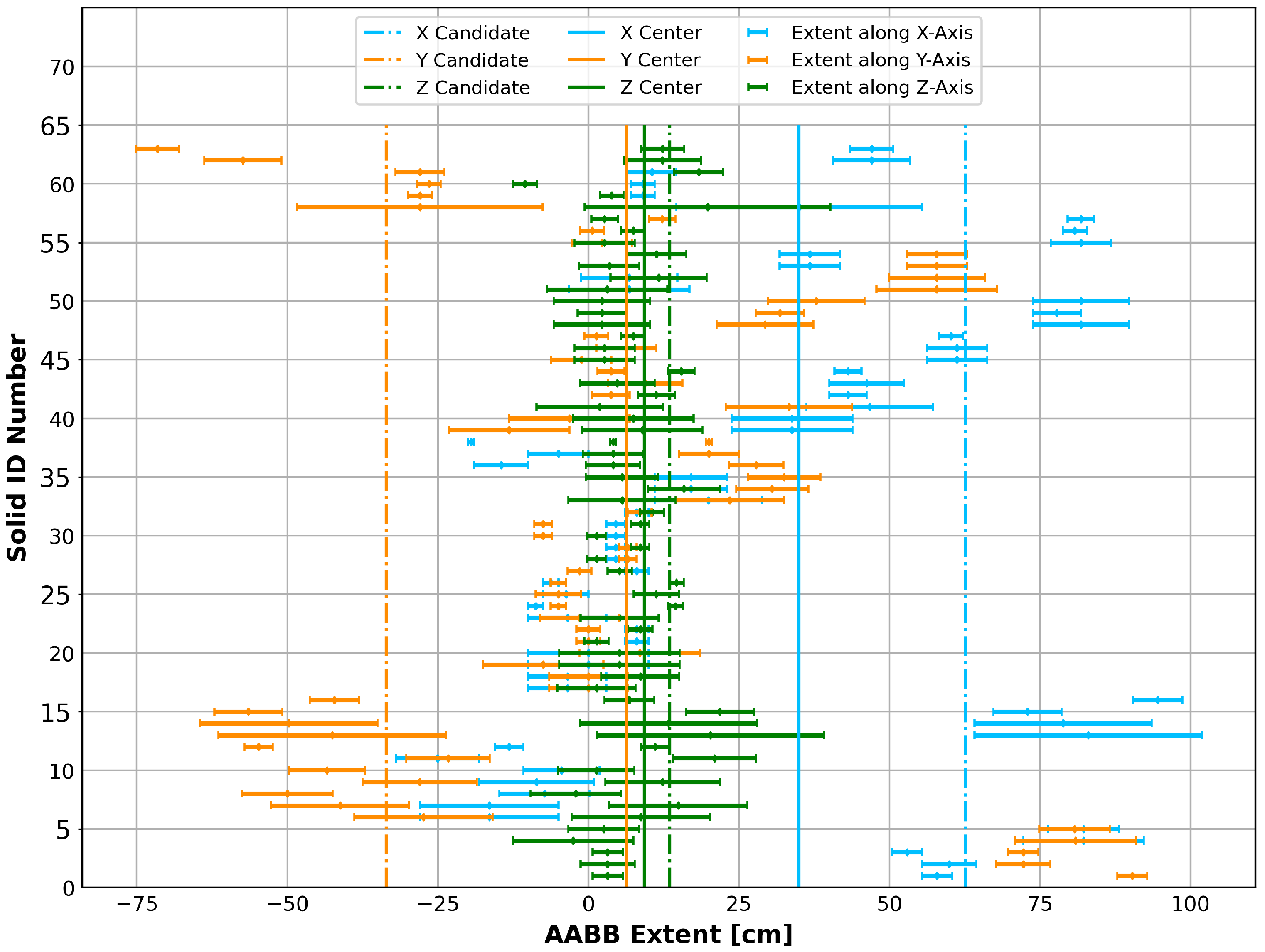
Figure 5b. The center and extent of the AABB of each subsolid along the X-, Y-, and Z-axis is plotted in Figure 6. For each horizontal line segment, the center point represents a subsolid’s AABB center, whereas the length represents its extent along the corresponding axis. Three candidate planes—along the X-, Y-, and Z-axis—were chosen by the density-informed selector, designated with the broken vertical lines. The candidate planes would cut through 3, 4, and 15 subsolids along the X-, Y-, and Z-axis, respectively. McCAD chose the one along the X-axis. If the old splitting scheme was used—three planes through the center of the void cell, as shown as the solid lines in Figure 6—then the plane through the Z-axis would cut though almost all solids, necessitating collision detection via OCCT functions on CAD solids.

4.2. Domain Decomposition: Hierarchical Void Cells

A first-of-a-kind capability of McCAD v1.0 is the generation of hierarchical void cells. Bounding volume hierarchy (BVH) has never been utilized for radiation transport in MC simulations, except for CAD-based codes such as DAGMC [5]. McCAD v1.0 void cell manager has the capability, through a user-controlled on/off input switch, to generate either conformal or hierarchical void cells. Hierarchical void cells form a binary tree with the root corresponding to the AABB of the entire CAD model. Using the advanced void cell manager described in Section 4.1, McCAD then splits the root void cell into two and progresses recursively down the tree. At each node, a void cell contains two daughter void cells, and the parent–daughter relation is captured. When splitting of void cells ceases, at which stage leaf nodes are formed, the void cells contain CAD solids from the model. This simplifies the CSG expression for most of the void cells in the model—a complement of only two rectangular prisms.
In MCNP, one of the resource-intensive processes involves the update to the state of the particle as it traverses the medium. It involves the calculation of surface crossings based on the distances to the boundary surfaces in the current cell. For a void cell, this means a calculation of the distance to all surfaces represented in the void cell definition. Thus, a complex/lengthy void cell expression would result in a slowdown of the radiation transport simulation. Hierarchical void cells provide a benefit to combat this slowdown; each void cell contains only two cells, with six planar surfaces each. This not only puts an upper bound on the number of calculations involved in determining the particle’s distance to the cell boundaries, but it also simplifies such calculations by using only planar surfaces.
To demonstrate this ability, the arbitrary collection of 63 solids referenced in Section 4.1 was utilized in a preliminary comparison of hierarchical vs. conformal void cells. By varying the number of solids per void cell in McCAD input, several MCNP input files were generated utilizing both hierarchical and conformal void cells. This parameter controls the material cells contained in all conformal and the inner-most hierarchical void cells, which determines the overall number of void cells in the MCNP input. Using the surface source defined by McCAD for stochastic volume calculation—defined on a sphere surrounding the solids with particles directed inward—the volumes of all voided material cells were calculated. The obtained results were identical because no changes to the material cells were made, but the structure of the void cells showed differences in terms of performance. MCNP6.2 was used to simulate 2 × 10⁸ histories on a single thread on 11th Gen Intel(R) Core(TM) i7-11850H @ 2.50 GHz.
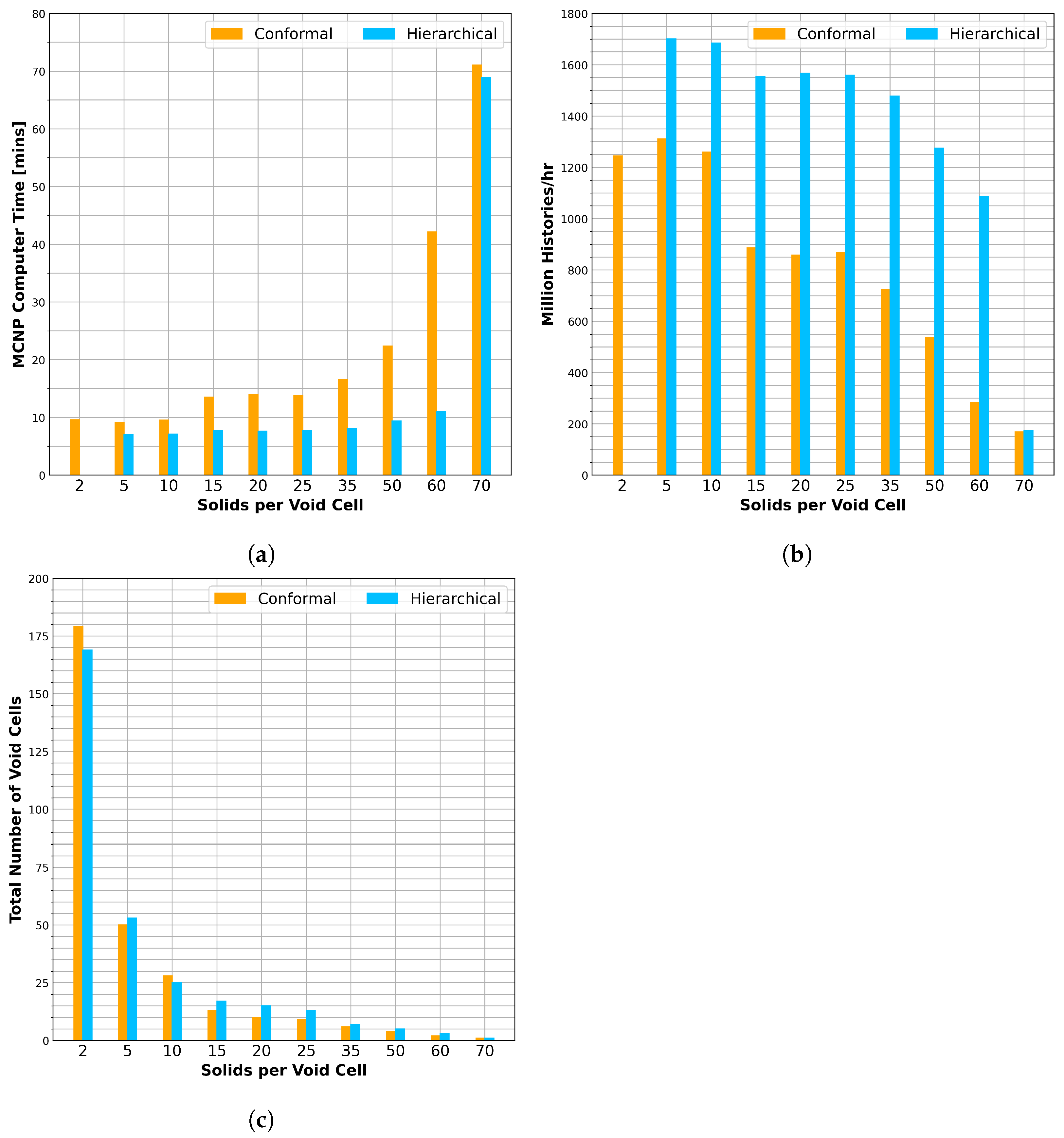
In Figure 7a,b, the computing time and the number of particle histories per hour, as reported by MCNP, are plotted against the number of solids per void cell, respectively. For the case with 70, a single void cell was generated in both cases, and the time and number of histories are similar. As the number of void cells increases, the number of solids per void cell decreases, demonstrating the performance gain. Both figures show that hierarchical void cells are superior to conformal ones in terms of lower computing times, which were up to 50% reduced, and higher processed particle histories per hour. Such a gain does not come at the expense of an increased number of void cells: the number is comparable in both cases, as demonstrated in Figure 7c.

4.3. Supplementary Output

When converting CAD models to CSG, in addition to checking for lost particles, volume validation is conducted to ensure that the deviation between CSG cells and CAD solids, if any, is kept to a minimum and that adequate density modifications are applied accordingly. This validation is performed through a one-to-one comparison between the original CAD solids, the sum of its subsolids after decomposition, and the stochastic volumes calculated in MCNP. McCAD v1.0 provides the necessary output to the user for this volume validation. When executed in decomposition mode, McCAD writes a list of all input solids names and volumes, as processed by OCCT, to a text file. When executed in conversion mode, McCAD produces mapping of cell IDs and the corresponding names and volumes of solids to a text file. This serves as a mapping between the cell IDs and the original input solids and their subsolids, making it easy to perform volume validation.
For conversion to MCNP, McCAD v1.0 provides two supplementary outputs. The first is in terms of a textual material-to-void cells mapping. This is beneficial in case any modifications must be implemented in the generated MCNP input file without the user repeating the conversion process all over again, although with the new conversion algorithm this difference has greatly diminished. Also, McCAD provides, in the MCNP input, auxiliary cells as well as surface, source, and tally definitions for stochastic volumes calculation.

5. Outlook

For future work, McCAD v1.0 is expected to undergo an extensive benchmarking and validation campaign. More capabilities are to be added to support processing solids with spherical and spline surfaces. The latter could open the door for modeling of complex shapes such as those encountered in stellarator designs, which as of this writing are supported only through CAD-based radiation transport codes. An extensive testing of the core algorithm could also lead to an optimized decomposition through an improvement of the surface selector heuristics.

6. Conclusions

This paper presents recent advances in the open-source code McCAD. In version 1.0 of McCAD, a new code structure has been realized. This includes using modern C++ coding standards and enforcing modularity that, in turn, ensures reusability and maintainability of the code classes and methods. Dependencies of the code have been limited to OCCT as a geometry engine and the Boost C++ library for parallel processing. The original decomposition algorithm from version 0.5 has been improved and expanded. By utilizing OBBs, unnecessary surfaces collision detection has been eliminated. Assisting splitting surface generation has also been expanded by including more use cases and new surface types: conical and toroidal. Pipework simplification has been implemented, a feature that ensures that the pipe configuration is maintained for models with tight tolerances.
A new conversion algorithm has been developed for version 1.0. The new algorithm is more robust than its predecessor, adding important new features. The automatic void generation has been implemented through an informed split plane selector and 1D-based collision detection. Unnecessary splitting of void cells has been eliminated, and more control over the void generation is granted to the user. Moreover, a new capability has been introduced to generate hierarchical void cells. A preliminary performance study demonstrated performance gains over conventional void cells. This could open the door for more optimization of radiation transport in complex models.

Author Contributions

Writing—original draft preparation, M.H.; writing—review and editing, M.H. and D.L.; supervision, D.L. and U.F.; project administration, D.L. All authors have read and agreed to the published version of the manuscript.

Funding

Development of McCAD was funded through EUROfusion as an implemented task under several work packages. For more details on funding, please contact Dieter Leichtle via dieter.leichtle@kit.edu.

Data Availability Statement

The data presented in this study are available on request from the corresponding author.

Acknowledgments

The authors would like to acknowledge the contributions of the original developer Lei Lu whose efforts in the original version of the code—McCAD v0.5—paved the way for the evolved and improved version, McCAD v1.0. Also, the authors appreciate the significant contributions of Christian Wegmann at the early stages of McCAD development. His dedication and programming expertise and skills helped the development tremendously.

Conflicts of Interest

The authors declare no conflict of interest.

Abbreviations

The following abbreviations are used in this manuscript:
KITKarlsruhe Institute of Technology
MCMonte Carlo
MCNPMonte Carlo N-Particle transport
CADComputer Aided Design
DAGMCDirect Accelerated Geometry Monte Carlo
BRepBoundary Representation
CSGConstructive Solid Geometry
UMUnstructured Mesh
STLSTereoLithography
LGPL-2.1GNU Lesser General Public License v2.1
OCCTOpen CASCADE Technology
OSOperating System
STEPSTandard for the Exchange of Product model data
OBBOriented Bounding Boxes
AABBAxis-Aligned Bounding Box
BVHBounding Volume Hierarchy

References

  1. X-5 MONTE CARLO TEAM. MCNPTM—A General Monte Carlo N-Particle Transport Code Overview and Theory Version 5 Vol. I; Report LA-UR-03-1987; Los Alamos National Laboratory: Los Alamos, NM, USA, 2003. [Google Scholar]
  2. Romano, P.K.; Horelik, N.E.; Herman, B.R.; Nelson, A.G.; Forget, B.; Smith, K. OpenMC: A State-of-the-Art Monte Carlo Code for Research and Development. Ann. Nucl. Energy 2015, 82, 90–97. [Google Scholar] [CrossRef] [Green Version]
  3. Leppänen, J.; Pusa, M.; Viitanen, T.; Valtavirta, V.; Kaltiaisenaho, T. The Serpent Monte Carlo code: Status, development and applications in 2013. Ann. Nucl. Energy 2015, 82, 142–150. [Google Scholar] [CrossRef]
  4. Valentine, A.; Berry, T.; Bradnam, S.; Hagues, J.; Hodson, J. Benchmarking of emergent radiation transport codes for fusion neutronics applications. Fusion Eng. Des. 2022, 180, 113197. [Google Scholar] [CrossRef]
  5. Wilson, P.P.; Tautges, T.J.; Kraftcheck, J.A.; Smith, B.M.; Henderson, D.L. Acceleration techniques for the direct use of CAD-based geometry in fusion neutronics analysis. Fusion Eng. Des. 2010, 85, 1759–1765. [Google Scholar] [CrossRef]
  6. DAGMC Supported Codes. Available online: https://svalinn.github.io/DAGMC/install/dagmc.html (accessed on 10 May 2023).
  7. Lu, L.; Qiu, Y.; Fischer, U. Improved solid decomposition algorithms for the CAD-to-MC conversion tool McCad. Fusion Eng. Des. 2017, 124, 1269–1272. [Google Scholar] [CrossRef] [Green Version]
  8. Fischer, U.; Grosse, D.; Lu, L.; Kondo, K.; Pereslavtsev, P.; Serikov, A.; Vielhaber, S. Applications of the McCad geometry conversion tool in fusion technology-ITER, IFMIF and DEMO. Trans. Am. Nucl. Soc. 2013, 109, 729–732. [Google Scholar]
  9. Wu, Y.; Song, J.; Zheng, H.; Sun, G.; Hao, L.; Long, P.; Hu, L.; FDS Team. CAD-based Monte Carlo program for integrated simulation of nuclear system SuperMC. Ann. Nucl. Energy 2015, 82, 161–168. [Google Scholar] [CrossRef]
  10. STL Format. 2019. Available online: https://www.loc.gov/preservation/digital/formats/fdd/fdd000504.shtml (accessed on 10 May 2023).
  11. McCAD-Salome. Available online: https://github.com/inr-kit/McCad-Salome-Binaries (accessed on 10 May 2023).
  12. Salome Version 7.4. Available online: https://www.salome-platform.org/ (accessed on 10 May 2023).
  13. McCAD-FreeCAD. Available online: https://github.com/inr-kit/McCAD-FreeCAD (accessed on 10 May 2023).
  14. FreeCAD. Available online: https://www.freecad.org/ (accessed on 10 May 2023).
  15. Harb, M.; Wegmann, C.; Fischer, U.M. McCAD v1.0L An Improved CAD to MCNP Interface Library. Trans. Am. Nucl. Soc. 2020, 122, 613–616. [Google Scholar]
  16. McCAD v1.0. 2022. Available online: https://github.com/inr-kit/McCAD-Library (accessed on 10 May 2023).
  17. Open CASCADE Technology v7.7.0. Available online: https://dev.opencascade.org/release (accessed on 10 May 2023).
  18. Boost C++ Libraries v1.81.0. Available online: https://www.boost.org/users/download/ (accessed on 10 May 2023).
  19. ANSYSTM SpaceClaim 2022 R1. 2022. Available online: https://www.ansys.com/products/3d-design/ansys-spaceclaim (accessed on 10 May 2023).
Figure 1. CAD-to-CSG conversion workflow.
Jne 04 00031 g001
Figure 2. Part of a decomposition tree of an arbitrary solid.
Jne 04 00031 g002
Figure 3. Decomposition using assisting surfaces (difference in colors signify disjoint solids).
Jne 04 00031 g003
Figure 4. Pipe decomposition in McCAD (difference in colors signify disjoint solids).
Jne 04 00031 g004
Figure 5. An arbitrary collection of solids, (a) original and (b) decomposed.
Jne 04 00031 g005
Figure 6. Distribution of AABB centers and extents of an arbitrary collection of 63 solids.
Jne 04 00031 g006
Figure 7. Conformal vs. hierarchical void cells: (a) MCNP computer time, (b) number of histories per hour, and (c) total number of void cells in the model.
Jne 04 00031 g007
Disclaimer/Publisher’s Note: The statements, opinions and data contained in all publications are solely those of the individual author(s) and contributor(s) and not of MDPI and/or the editor(s). MDPI and/or the editor(s) disclaim responsibility for any injury to people or property resulting from any ideas, methods, instructions or products referred to in the content.

