Article

Seamless Function-Oriented Mechanical System Architectures and Models

Institute for Machine Elements and Systems Engineering, RWTH Aachen University, Schinkelstraße 10, 52062 Aachen, Germany
*
Author to whom correspondence should be addressed.
Eng 2024, 5(1), 301-318; https://doi.org/10.3390/eng5010016
Submission received: 11 December 2023 / Revised: 29 January 2024 / Accepted: 2 February 2024 / Published: 6 February 2024

Abstract

:
One major challenge of today’s product development is to master the constantly increasing product complexity driven by the interactions between different disciplines, like mechanical, electrical and software engineering. An approach to master this complexity is function-oriented model-based systems engineering (MBSE). In order to guide the developer through the process of transferring requirements into a final product design, MBSE methods are essential. However, especially in mechanics, function-oriented product development is challenging, as functionality is largely determined by the physical effects that occur in the contacts of physical components. Currently, function-oriented MBSE methods enable either the modeling of contacts or of structures as part of physical components. To create seamless function-oriented mechanical system architectures, a holistic method for modeling contacts, structures and their dependencies is needed. Therefore, this paper presents an extension of the motego method to model structures, by which the seamless parametric modeling of function-oriented mechanical system architectures from requirements to the physical product is enabled.

1. Introduction

The objective of product development is to translate the customer’s expectations regarding the product’s behavior and functions into a manufacturable product. Today, one of the key success factors for the competitiveness and innovative strength of a company lies in mastering this translation process, despite the continuously increasing level of product complexity [1,2,3,4]. This complexity is mainly driven by growing physical and logical interactions (especially on the product layer) due to the high integration of different disciplines of mechatronic products, like mechanical, electrical and software engineering [5,6,7,8,9,10]. Whereas software engineering realizes product functions by immaterial software code, mechanical components have to be developed and manufactured based on physical laws to achieve the desired physical product behavior [11]. In mechanics, the physical product behavior is mainly influenced by physical effects which occur in a contact area of two mechanical components [12,13,14]. Therefore, the design of the contact geometry and the choice of interacting materials are crucial factors in the development of mechanical subsystems.
Recent research in model-based systems engineering (MBSE) [15,16] has provided approaches to describe mechanical subsystems as part of complex mechatronic products, e.g., in [17,18,19,20,21,22]. The core idea of these approaches is the establishment of a discipline-neutral functional architecture that serves as a consistent basis for discipline-specific development methods [23]. For the function-oriented development of mechanical subsystems, the formalized modeling of contacts (e.g., the shaft and hub surface of a shaft–hub-connection) [5] and the virtual validation of functional requirements via the linking of domain models [24,25,26] represent a decisive basis. As mechanical subsystems (e.g., the shaft and gear wheel) consist of contacts and their connecting structure, it is also necessary to test entire components. Furthermore, to manufacture the functionally developed components and to manage them within distribution, the product description up to the bill of materials (BoM) is required as well. Thus, the following five criteria are relevant to enable the seamless function-oriented modeling of mechanical system architectures:
  • Based on a function-oriented system architecture.
  • Linking domain models for function validation.
  • The formalized modeling of physical contacts.
  • The formalized modeling of physical structures.
  • The formalized modeling of relations between physical contacts and structures.
However, no current MBSE modeling method combines all five previously mentioned criteria (cf. Section 2). Therefore, the objective of this paper is an approach for the function-oriented modeling of mechanical system architectures. The paper is structured as follows: Section 2 provides an overview of current approaches to model system architectures, with a particular view of modeling contacts and structures. Subsequently, Section 4 is derived from the state of the art, and the research questions of this paper are defined. The main section presents a modeling method for the function-oriented modeling of mechanical system architectures, including the definition of the structure elements, the integration of domain models into the structure elements and the arranging of the components at the product level. Finally, Section 6 and Section 7 conclude this paper. The developed modeling approach is illustrated by its application to the example of a centrifugal pump.

2. State of the Art

MBSE is the formalized application of modeling to support requirements in engineering as well as the development and validation of (technical) systems over the entire product lifecycle [27]. By creating an interdisciplinary system model as its key element, MBSE centrally manages all domain models and the information of product development and links them [27,28,29,30]. The system thus represents a formalized representation of the product [27,28,29,30]. To model system models, textual and graphical modeling languages are used. In many industries, the graphical general-purpose modeling languages Systems Modeling Language (SysML) of the Object Management Group, which is based on the Unified Modeling Language (UML), has become established [8,31,32]. For in-depth information about further languages, as well as the advanced language profiles being used, such as MODELICA and KARMA, and an overview of the development of the MBSE and its application in industrial practice, please refer to the survey papers [8,16,33].
In the following section, state-of-the-art approaches to model discipline-neutral system architectures are analyzed, with the focus on mechanical engineering. The approaches are analyzed with regard to the five criteria listed within the introduction. Therefore, the following five subsections each briefly explain the regarded criterion before the state-of-the-art approaches are analyzed subsequently.

2.1. Analyzed Criterion: Based on a Function-Oriented System Architecture

A promising approach to master the complexity of mechatronic products caused by interactions between mechanics, electrics and software is the function-oriented application of MBSE. In function-oriented product development, the function architecture is built as the central element that structures all interactions by the functional decomposition of the product [11]. Functions describe the product’s behavior without specifying how the behavior is realized, which allows all technical disciplines to provide alternative technical solutions for the same function [5]. Therefore, a function’s solution-neutrally defines the transformation of functional flows that enter and leave a function. Within design methodology, the differentiation of functional flows as energy, material or signal flows is established. However, among the current function-oriented methods to model MBSE system models, such as Digital Function Modeling in DC43 [34], FAS4M [35], Functional Product Description [2]/mecpro2 [36], Integrated Product Model for Conceptual Design [37], MagicGrid [38], the motego method [5], OpenSE/OpenMBEE [39] and SYSMOD [40], the modeling of functions, and especially the consideration of functional flows, differs:
  • Usage of functional flows is not specified [34].
  • Focus on the modeling of signal flows [38,39].
  • The modeling of all three established functional flows (energy, material and signal) is provided [2,5,35,36,37,40].
In mechanical system architectures, as discussed in this paper, functions are realized through physical components and their interaction. These interactions are mainly described by the exchange of energy. Therefore, products in mechanical engineering cannot be modeled via methods that are limited to the consideration of signal flows.

2.2. Analyzed Criterion: Linking Domain Models of Product Development for Function Validation

An MBSE system model is a descriptive representation of a product to be developed. However, in order to develop the product in accordance to the requirements and to validate the fulfilment of the requirements, the behavior of the product needs to be described. For this description of the product behavior, domain models must be linked to the system model and connected to all parameters of the other constitutes of the system elements [5]. Domain models are simulation models which abstractly describe a particular real system and which are used to predict the physical behavior of a product [25]. By linking domain models to the system model, e.g., with the methods MagicGrid [38], motego [5] and OpenSE/OpenMBEE [39], MBSE enables the virtual validation of requirements as well as the identification of the optimal combination of technical solutions for the product concept. Several approaches to establish interfaces between MBSE system models and domain models have been developed. An overview of the exchange of parameters of SysML-based system models and domain models are provided by [41,42,43]. As examples, the approach according to [44] for the transformation of system models with MODELICA simulation models, and the approach according to [45] for the automatic generation of analysis models, are mentioned in [26]. A more detailed overview on the integration and coupling of simulation models is provided within [26], which also presents a model signature for the integration of simulation models into system models.
Depending on the product development phase, it is usually necessary to use domain models of different fidelity levels (“To which accuracy are the physical quantities calculated for the represented systems?”) for the same purpose. To enable the simulation of the appropriate domain model, the modeling method has to allow the efficient exchange of domain models. The only approach that sufficiently fulfils those requirements is the modeling method for the integration of domain models in the SolutionElements of the motego method according to [25].

2.3. Analyzed Criterion: Formalized Modeling of Physical Contacts

Within mechanical engineering, the interaction between two components occurs via physical contact. The listed state-of-the-art modeling approaches can be divided into the following categories to describe the contacts:
  • Description of physical contacts not explicitly considered [2,34,35,36,37,38,39,46,47,48,49].
  • Description via a connector between single active surfaces of two different structures [40,47,50,51,52].
  • Description through sketches [35,53].
  • Description of single active surfaces and the energy flows between them [37].
Besides the ability to model the geometry of contacts, the modeling of its physical effects is essential for the description of the physical behavior and necessary for the model-based validation of mechanical system architectures. Only the approaches FAS4M and System Sketcher provide a method to model the physical effects occurring within contacts [35,53]. However, the active surfaces of contacts are not described parametrically, but via sketches. Thus, the influence of the contact geometry on function fulfilment is not formalized and can therefore not be tested.
Among the methods shown in Table 1, only FAS4M and motego provide an approach to model contacts with their active surfaces and the occurring effects. In contrast to the SysML dependency generalization in motego, FAS4M uses the less formal SysML dependency trace to connect functions and contacts [35]. As a result, within the FAS4M approach, the functional flows energy, material and signal are not inherited by the contacts, and thus are not available for the design and testing of the contacts.

2.4. Analyzed Criterion: Formalized Modeling of Physical Structures

The design of mechanical subsystems not only contains interacting surfaces, but also a connecting structure of these surfaces with each other that is characterized by geometric and material properties. In the approaches C&C2-Approach [50,51,52,54], Digital Function Modeling in DC43 [34], Functional Product Description [2]/mecpro2 [36], Integrated Product Model for Conceptual Design [37], MagicGrid [38], Mechatronic Modeller [46], OpenSE/OpenMBEE [39], SPES [47,49], STRATA [48] and SYSMOD [40], structures are modeled using SysML blocks with parameters, respectively UML classes with attributes. The parameter-based modeling of structures offers the potential to seamlessly link not only the whole SysML block with respect to the UML class, but also specific parameters (e.g., mass and strength) to the requirements and models. This linking enables the efficient testing and design of structures, as the fulfilment of requirements can be validated at early-development stages. FAS4M and Systems Sketcher, in contrast, describe structures via sketches [35,53], resulting in high efforts for the testing and designing of structures according to the requirements, while the motego method, according to [5], does not provide the modeling of structures.

2.5. Analyzed Criterion: Formalized Modeling of Relations between Physical Contacts and Structures

To seamlessly achieve the described mechanical system architectures, the formalized modeling of relations between contacts and structures is essential. The analyzed approaches shown in Table 1 can be divided into the following two categories regarding the relation between contacts and structures:
  • FAS4M uses the SysML dependency trace to model the dependencies between the contacts with their active surface set and structures [35].
  • The other listed state-of-the-art approaches link individual active surfaces to structures, either as the parts or as ports of structures. Of these, the C&C2-A [50,51,52,54] is to be pointed out, because linking active surfaces with structures via ports seems to build a suitable basis, since the ports can be linked to active surfaces within the contact elements, as, for instance, the SolutionElement of the motego method, according to [5]. However, the C&C2-A does not allow a parametric description of contacts, as the contacts are not specifically modeled, but realized through connectors between two active surfaces.
The modeling of active surfaces as parts only allows the description of individual active surfaces, but not how the active surfaces are connected and interact with each other. The modeling with trace dependencies instead does not enable the transfer of parameters between the contacts and structures, but rather describes that they are related.
Table 1 provides a qualitative overview of the findings generated by the analysis of the state-of-the-art approaches C&C2-A [50,51,52,54], Digital Function Modeling in DC43 [34], FAS4M [35] and System Sketcher [53], Functional Product Description [2]/mecpro2 [36], Integrated Product Model for Conceptual Design [37], MagicGrid [38], Mechatronic Modeller [46], motego [5], OpenSE/OpenMBEE [39], SPES [47,49], STRATA [48] and SYSMOD [40].
Existing modeling methods either focus on the formalization of only one development artefact (contacts or structures) or lack possibilities for linking domain models with the modeling of technical solutions, so that contacts and structures cannot be tested within the system model. Hence, the objective of this paper is to elaborate a method for the function-oriented modeling of mechanical structures on the basis of contacts, test them by linking domain models and enable the arrangement of components on the product layer according to structuring criteria, such as assembly.
When elaborating a new modeling method that focuses only on a part of the product development process, it is reasonable to integrate the method into a suitable broader framework, if possible. The motego method, according to [5], represents such a promising framework (cf. Table 1). Therefore, the motego method is explained in the following section, and the current limitations of the method are outlined using the example of a centrifugal pump.

3. The motego Method

The motego method (short for Model–Test–Go, formerly referred to as the MSE Architecture) [55] represents an MBSE method for the seamless, function-oriented development of mechatronic systems [5]. Therefore, the motego method provides approaches for modeling Requirements, Functions and Solutions, as well as their parametric linking (highlighted in red, orange and blue colors in in Figure 1). Requirements are linked to a functional decomposition of the product, which describes the behavior of a product solution-neutrally by the changes in the functional flows [5]. How these changes in functional flows are realized is concretized on the Solution layer via the SolutionElements and the superordinate SystemSolutions. The SystemSolutions, in turn, can consist of several SolutionElements [5]. For more information about the motego method to build MBSE system models, please refer to [5]. Like in this paper, the motego method is constantly being expanded. For example, a method-specific SysML language profile exists to apply the function-oriented modeling with motego [56]. In order to list just an excerpt of further work related to the motego method, we refer to the following publications: [24,25,26,55,57].
In mechanical subsystems, functions are realized through interactions at contact surfaces [58]. Within the motego method, these contact surfaces are referred to as ActiveSurfaces [5]. Two ActiveSurfaces that are in contact with each other form an ActiveSurfaceSet. The ActiveSurfaceSet, in turn, is modeled as a part of the SolutionElement, which is linked to the functions with the SysML dependency generalization, as shown in [5]. In combination with the PhysicalEffect as part of the SolutionElement, this linking enables the virtual validation of the functional requirements, as well as design requirements, that are related to the contacts modeled via SolutionElements in early-development stages [5].
However, this limitation of the motego scope, according to [5], to validate contact-based design requirements does not allow the entire testing of, e.g., strength requirements. For example, it is not sufficient to only consider the ActiveSurfaces for an FEM analysis that is used in a model chain to test the strength. Instead, the connecting structure between ActiveSurfaces needs to be considered as well (green highlight in Figure 1) within the product development. To enable the entirely seamless product development from the requirements of the physical product, the motego method needs to be extended by a modeling method for structures. Such an extension needs to formalize the relations between physical contacts and structures. For this formalization, the modeling method has to contain mechanisms to assign the ActiveSurfaces to structures, as well as the description of the dependencies between the active surface parameters and the structure parameters. In addition, the linking of structures to requirements has to be ensured, and the fulfilment of these structure-related requirements has to be verifiable.
Another aspect is the processability of the development results by the departments following in the value chain, such as purchasing, logistics, manufacturing and assembly. Enterprise Resource Planning (ERP) and Product Data Management (PDM) systems are established in companies for the cooperation of people which are involved in the product development. The ERP and PDM systems support the management of geometry data, as well as the planning of material procurement and manufacturing steps. While the motego method is used to consistently build the architectures of functions and contacts with respective solutions in product development, the ERP and PDM systems typically capture the architectures of the components. An example is the BoM, which hierarchically structures a product in the assembly sequence. In order for functional architectures and product structures, such as the BoM, to exist in parallel and synchrony, it is important that functionally developed structures can be rearranged at the product layer according to structuring criteria, such as assembly.

4. Research Need

In summary, the motego method is able to map mechanical solution concepts in a function-oriented way and link domain models to them. However, motego lacks a method for the function-oriented modeling of mechanical structures. This leads to the following three research questions of this paper:
  • How can structures be defined so that they can be assigned to functions?
  • How can domain models be integrated to enable the design and validation of structures according to the requirements?
  • How can the defined structures be arranged at the product layer to synchronize them with data management systems?
As justified before, the modeling approach to be developed is intended to be an extension of the SolutionElements within the motego method [5]. The approach is presented in the following section by addressing each research question within a separate subsection.

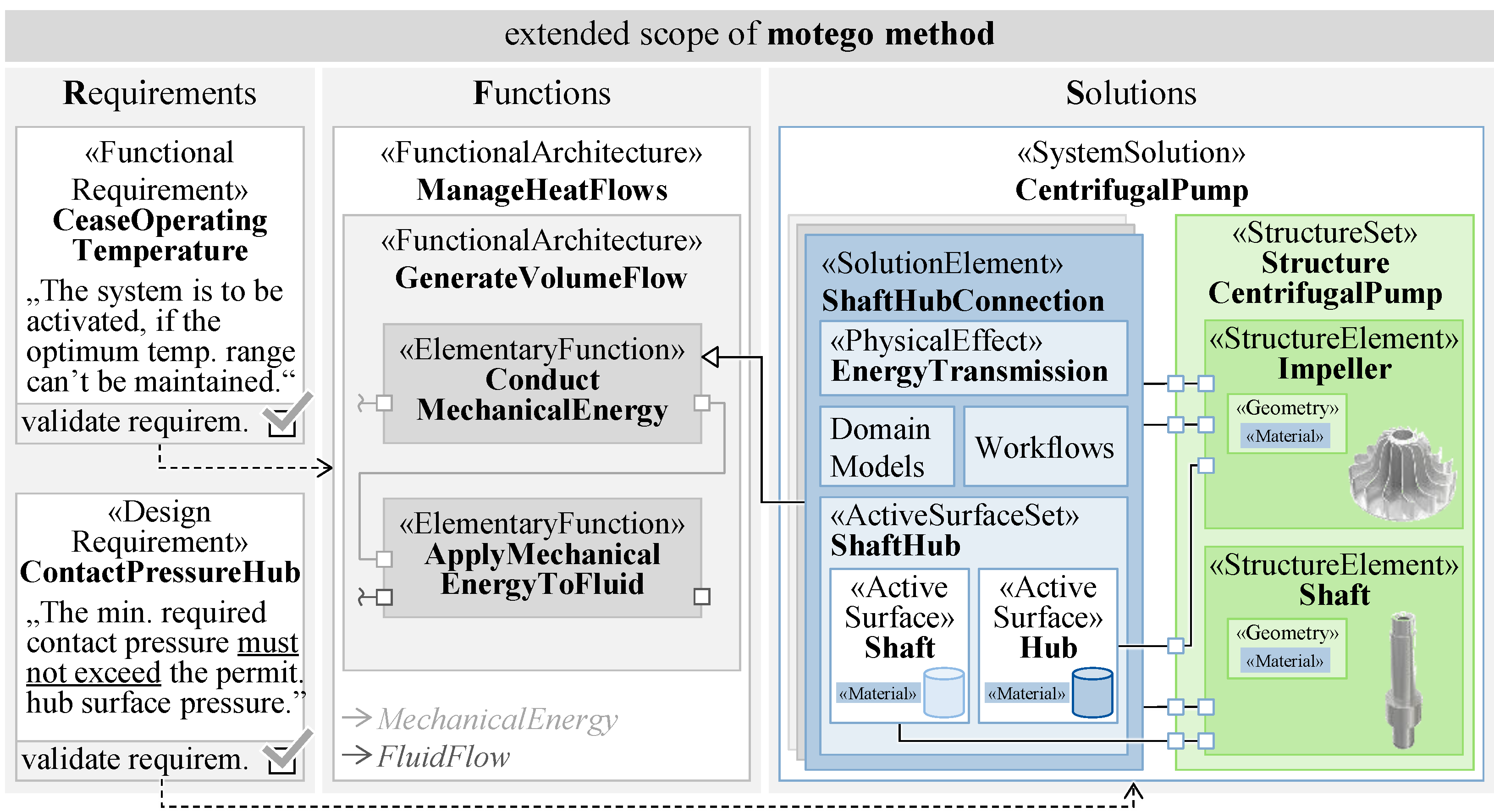
5. Function-Oriented Modeling of Mechanical System Architectures

This section presents the method to model structures within motego. The presented modeling approaches are applied to an exemplary centrifugal pump to continue the example presented in [5,11].

5.1. Definition of Structure Elements Based on Function-Oriented Contacts

The modeling of mechanical components with the motego method, according to [5], is limited to the contacts, which are represented by SolutionElements. The SolutionElement contains the ActiveSurfaceSet with a parametric description of the geometry and the material properties of two contacting ActiveSurfaces, as well as the PhysicalEffect as the first simplified behavior description. In addition, the validation and optimization of the contacts can be performed through DomainModels and Workflows [5,25,26]. Regarding mechanical system architectures, the two ActiveSurfaces finally have to be provided by two structures. In consequence, motego has to be extended by a modeling method for structures. As Figure 2 shows for the exemplary centrifugal pump, the structures, referred to as StructureElements (green highlight in Figure 2), extend the motego solutions. The modeling of StructureElements and their connection to ActiveSurfaces is described in the following subsection using a metamodel (cf. Section 5.1.1), and subsequently applied to the example of the centrifugal pump (cf. Section 5.1.2).

5.1.1. Metamodel for Modeling Structure Elements

Within the motego method, according to [5], SystemSolutions can be decomposed into other SystemSolutions or SolutionElements. To follow this hierarchical decomposition, the extension of the motego method not only has to include the StructureElement as the representation of components, but also the superordinate StructureSet. This StructureSet, in turn, can consist of several StructureElements (green highlight in Figure 3). To enable the seamless creation of StructureElements from ActiveSurfaces, it has to be defined which ActiveSurfaces are realized by which StructureElement. A component typically realizes ActiveSurfaces from different solutions. Therefore, all relevant ActiveSurfaces of the subordinate solutions are assigned to the StructureSet as the physical interfaces of the structures via the SysML element full port (blue highlight in Figure 3). Subsequently, the full ports of the StructureSet have to be connected to the respective full ports of the StructureElements.
For the function-oriented development of StructuralElements, not only the ActiveSurfaces have to be assigned to these, but also the dependencies between the parameters of the ActiveSurfaces among each other and with the connecting structure have to be modeled. To define these dependencies, it is necessary to describe the structures parametrically. Comparable to ActiveSurfaces [5], the parametric description of StructureElements is based on geometry and material. In addition, the geometry parameters of the structure itself are added to the StructureElement to fully define its geometry. To ensure consistency between the geometry and material parameters of the ActiveSurfaces and StructureElements, the relations of the parameters have to be defined. Since the ActiveSurfaces are assigned to the StructureElements via full ports, bidirectional parametric links are implemented. Thus, the geometry parameters and the material of the ActiveSurfaces are passed to the StructureElement that physically has to fulfil them (cf. Figure 3).

5.1.2. Exemplary Application of the Structure Element Metamodel

In the following, the described metamodel is applied to an exemplary centrifugal pump. For the development of the pump structure, the structure set StructureCentrifugalPump is created (light-green highlight in Figure 4) and the ActiveSurfaces of the solution elements ShaftHubConnection and CentrifugalPumpWheel are assigned as full ports. Subsequently, the structure elements Impeller and Housing are created within the StructureSet. The application in Figure 4 shows the assignment of the active surfaces Hub and Wheel to the Impeller. The full ports of the StructureSet and the StructureElement are finally linked with connectors. By this assignment, the Impeller contains the active surface Hub of the ShaftHubConnection and the active surface Wheel of the solution element CentrifugalPumpWheel.
One challenge in corporate practice is to provide all collaborating developers with current and valid data, and to inform them transparently about changes. In the example described, the CentrifugalPumpWheel could be designed by a simulation expert with a focus on fluid engineering optimization, while the component Impeller is designed by a design engineer to be suitable for casting. Both employees pursue important goals to ensure that the final product is functional and can be manufactured. At the same time, both access the same geometric parameters and calculate or reuse them. Due to the complexity described above, current mechatronic products have a high number of physical and logical interfaces where a high number of parameters are commonly used and must always kept consistent. This task has so far been ensured by the swarm intelligence of well-practiced employees and established company processes, but requires model-based support for sustainable knowledge storage and to master more complex products. The modeling proposed here inherently ensures that, for example, if the CentrifugalPumpWheel is changed by the fluid expert, an impending conflict can be detected in a model-based manner. This conflict can subsequently be resolved, e.g., by a note to the responsible expert or by the automated execution of a generative design process for the Impeller. In reality, an initial change can potentially trigger high impacts on a wide variety of parts of the system. The modeling method described enables these change effects to be transparently identified and evaluated a priori in the future on the basis of the parameter linkage.
In the modeling method presented, StructureElements are defined on the basis of ActiveSurfaces. Thus, with regard to the system architecture of the motego method shown in Figure 1, a parametric link from requirements via functions and solutions up to the StructureElements is created. This seamless parametric description provides a basis for testing the design requirements that are related to the structures. However, the validation of such design requirements requires integrated domain models.

5.2. Integration of Domain Models into Structure Elements

Domain models are defined as simulation models that describe a specific real system behavior in an abstract form for a specific purpose, such as a finite element simulation for the deformation calculation [5]. Usually, domain models are not used as stand-alone models, but are interconnected via their input and output parameters [24,25]. Spütz et al. describe an approach for the motego method that contains engineering models, production models and controlling models to test and design technical solutions with respect to the requirements [25]. Within this paper, the metamodel according to [25] is adapted for the integration of domain models into the motego system model to be used for the validation of the requirements associated with the StructureElements.

5.2.1. Exemplary Application of the Spütz et al. Metamodel

In the following, the different categories of domain models and their respective integration into the MBSE system model of the product to be developed are described.
Engineering Models: Engineering models describe a certain scope (e.g., contact, bearing, drive train and the whole vehicle) of the system under development concerning a specific purpose (e.g., strength, noise vibration harshness and heat exchange) with a specific model fidelity (e.g., characteristic curves, analytical equations and numerical approximations). Engineering models with the scope of a single contact of an ActiveSurfaceSet are integrated into the SolutionElements and can calculate the physical behavior of the contact based on the parameters that are defined in the SolutionElement and its ports. If an engineering model represents a broader scope (e.g., multiple contacts and certain components), the engineering model is integrated into the respective SystemSolution that fully contains this broader scope (cf. Figure 5). Since the behavior of structures always occurs through the interaction via ActiveSurfaces with at least one other structure, engineering models are not integrated within StructureElements but rather into the superordinate SystemSolution.
Production Models: Production models describe the process steps to manufacture StructureElements and assemble them. The production process includes the production planning, the manufacturing of StructuralElements using specific production machines (e.g., a CNC milling machine, a grinding machine or an FDM 3D printer) and the assembly of the StructuralElements to Modules and the overall product. The production machines are not part of the technical system to be developed but are used for manufacturing or assembling the StructuralElements of this system. Thus, production models are not part of the MBSE system model of the system to be developed. Instead, the references are integrated into the system model as interfaces that enable access to the production models, and therefore plan and validate the manufacturing and assembly of the StructuralElements.
Controlling Models: Controlling models are used to estimate and calculate the costs arising from the development of a product over the material costs up to the production. Like in production models, controlling models are not part of the system to be developed. So, instead of the controlling model itself, the references to access the model are integrated into the system model.
The execution of these interconnected model networks, and thus the order of the models, is controlled by workflows [57]. These workflows are modeled as SysML behavior elements, like activities and interactions within the StructureElement or the superordinate SystemSolution, which contains the domain models to be controlled by the workflow [57].

5.2.2. Exemplary Application of the Domain Model Metamodel

The previously elaborated metamodel to integrate domain models is applied to the example of the centrifugal pump in the following subsection and illustrated by an exemplary engineering model.
Engineering Models: To describe the integration of engineering models associated with StructureElements, the ShaftHubConnection between the Shaft and the Impeller (cf. Figure 5) of the centrifugal pump is regarded in detail. The ShaftHubConnection represents a cylinder press fitting, which is realized by joining two StructrualElements each with overmeasured ActiveSurfaces. The overmeasure fitting is defined by the dimensions of the two active surfaces (and their tolerances) in contact with each other (cf. Figure 4, Figure 5 and Figure 6). Fitting both StructrualElements by force creates a consistent pressure throughout the contact that results in an adhesive force which is capable of transmitting constant, alternating and impact torques, as well as longitudinal loads. The ShaftHubConnection of the exemplary centrifugal pump has to transmit torque from the Shaft to the Impeller to finally generate a volumetric flow of a fluid. Figure 6 exemplarily shows the integration of an engineering model for the verification of the permissible contact pressure for the structure element Hub (according to a calculation process described in [59]). For its calculation, the engineering model needs input data from certain parameters of the solution element ShaftHubConnection and the structure elements Shaft and Impeller. With the FactorOfAdhesiveSafety and the FactorOfApplication, two input values are also defined via requirements (highlighted in red color in Figure 6). For this purpose, the engineering model checks whether the minimum required contact pressure is lower than the permitted surface pressure of the structure element Hub. If this is the case, the Boolean ValidPressure as the output value of the model is set to true.
If the requirement is not fulfilled and the resulting pressure is too high, the hub can be damaged. The pressure depends on the load case, the materials of the fitted StructuralElements and the geometries. Thus, the wall thicknesses of the StructuralElements have a decisive influence on the behavior. In order to reduce the mass of the accelerated StructureElements, the Shaft has a continuous inner drilling. Since this drilling is not in contact with another StructureElement, its geometry is not defined by an ActiveSurface. The influence of the StructureElement Shaft on the ShaftHubConnection illustrates the necessity to model both the SolutionElements and StructureElements in a harmonized and interrelated manner, and to integrate domain models into those specific model elements that provide the best access to relevant parameters, as well as the broadest solution reuse.
The collaboration of the presented modeling approaches enables the development and optimization of the mechanical system architecture up to the final design. This modeling enables the identification of a valid overall product design by taking all parameters, their specific restrictions and multidimensional dependencies into account.

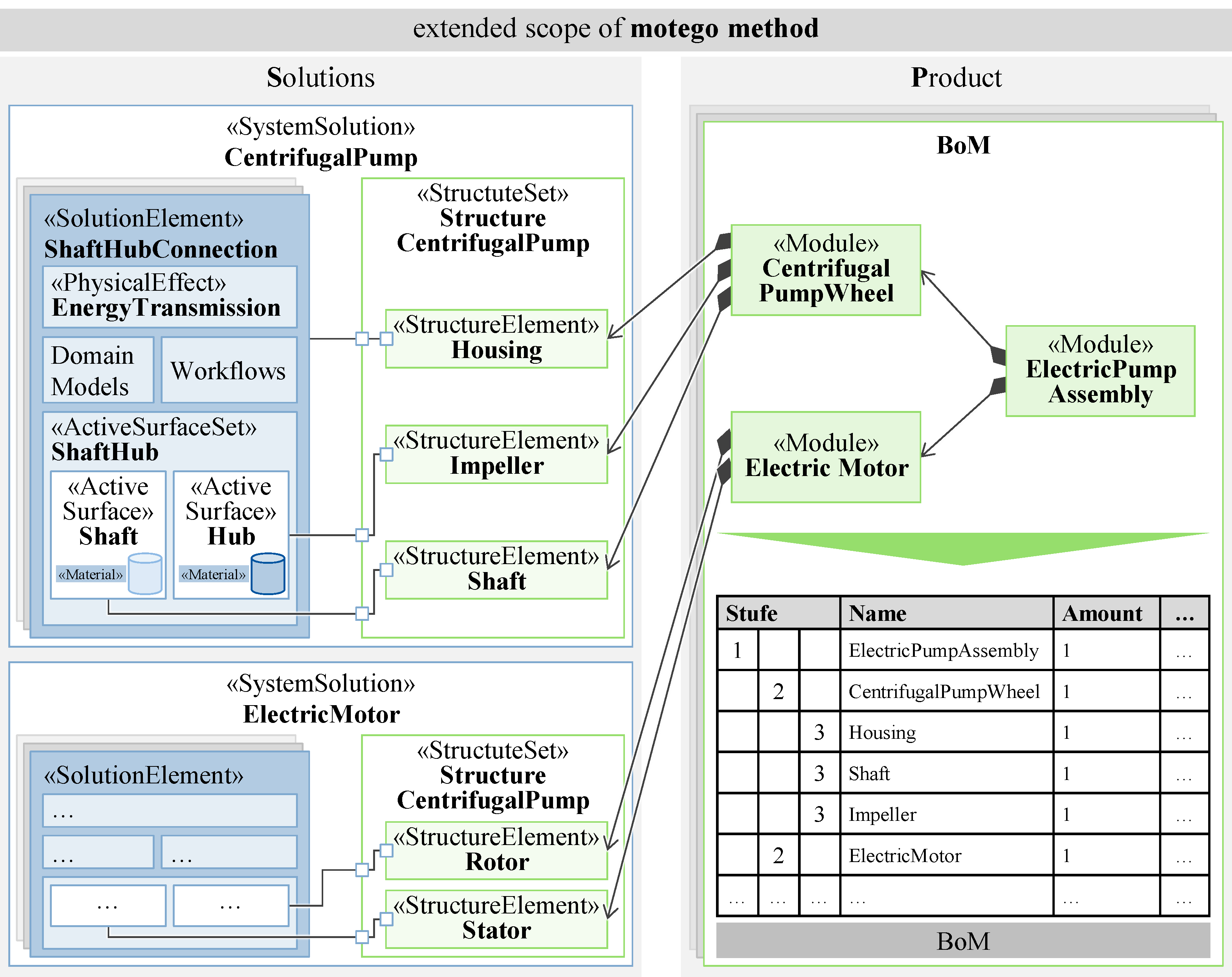
5.3. Arranging Structure Elements at the Product Layer

Within manufacturing companies, the PDM and ERP systems have become established as the central interfaces to control the data and processes of product development through the distribution of information across all participating departments. The PDM and ERP systems typically capture the architectures of components (equivalent to the StructureElements), like the BoM, instead of the functional architectures as the basis of product development within the motego method. The BoM structures the components of a product hierarchically in terms of the sequence of the assembly during production. In addition to information about the components and their setup in the modules, the BoM serves to control the supply chain, work preparation and production. [60]
To combine and synchronize the function-oriented application of the MBSE and the managing of the product orders with the established PDM and ERP systems using the BoM, components that have been developed based on functions need to be rearrangeable according to structuring criteria, such as assembly or controlling. Therefore, we propose the extension of the motego method by a Product layer within the scope of this paper (cf. Figure 7). The product layer follows as the fourth layer after the Requirements, Functions and Solutions. In order to enable the arrangement of the previously introduced StructureElements with regard to the different phases of a product lifecycle, the motego method is extended by the stereotype Module (cf. Figure 7). StructureElements can be assigned to a Module via the SysML dependency directed composition. This dependency expresses that a Module is composed of the associated StructureElements. Figure 7 shows the application of this modeling approach by using the centrifugal pump. Within the example, the product ElectricPumpAssembly is structured into preassembled modules respecting the final assembly sequence. Therefore, the module CentrifugalPumpWheel consists of the structure elements Housing, Impeller and Shaft, whereas the module ElectricMotor contains the Rotor and the Stator. In general, a Module can consist of further subordinate Modules or StructureElements. The BoM can be derived directly from the architecture of Modules and StructureElements which is generated by the sequence of assembly.
With the extension of the motego method by the Modules and the Product layer, functionally oriented developed structures can be arranged according to all criteria of the product lifecycle phases, like manufacturing, assembly, procurement, distribution, service and recycling. The arranging of the StructureElements represents the link to the BoM as the leading document of the current PDM and ERP systems, and thus to established product development processes. Despite the logical foundation of this contribution, one important future challenge will be the seamless coupling of MBSE system models with the PDM and ERP systems via software interfaces.

6. Discussion

The contribution of this paper is the extension of the motego method, according to [5], by a modeling method for structures (the extension is highlighted by color in Figure 8). The added value created by extending the motego method is illustrated for the application example of a centrifugal pump. In terms of mechanical engineering, the motego method, according to [5], has been limited to the modeling of physical contacts (ActiveSurfaces), such as the Shaft and the Hub of the solution element ShaftHubConnection, as shown in Figure 8. Therefore, the ActiveSurfaces could already be defined parametrically (e.g., in terms of their dimensions and materials), according to [5], but it has not been possible to validate whether the required contact pressure of the shaft–hub connection is satisfied. This can be illustrated by the example of the wall thickness of the Shaft, which affects the resulting contact pressure: a continuous drilling within the Shaft to reduce the rotating mass could be considered and would affect the wall thickness. However, as the surface of this continuous drilling is not in contact with another structural element, its dimensions cannot be specified via an ActiveSurface (cf. Figure 6). Therefore, the motego extension presented in this paper enables the modeling of structures as well as the definition of which contacts shall be realized by a structure.
Through the integration of simulation models into the presented framework, mechanical system architectures can be efficiently tested and optimized with regard to requirement and function fulfilment. As a result, product failures, such as critical material stresses leading to the damage of the Shaft, can be identified and eliminated in earlier development stages.
However, a major drawback of the presented modeling method remains the initial modeling effort. To justify the modeling efforts in practice, the method is currently mainly applicable to products whose parts are reused over several product generations or whose complexity could otherwise only be mastered at great expense. Initial approaches to overcome this limitation may be the reuse of existing modeled system elements from solution libraries, as shown in [5]. In addition to reuse, another approach to reduce the modeling time is to accelerate the development process, e.g., by the method-specific SysML profiles for common modeling tools [56]. Furthermore, the presented approach is currently limited to MBSE modeling environments. As product development is followed by further steps, like purchasing, logistics, manufacturing and assembly, in which the PDM and ERP systems are used, the required interfaces and processes to link MBSE environments have to be examined.

7. Conclusions and Outlook

The function-oriented application of MBSE represents a promising approach to master the increasing complexity in today’s product development [61]. In particular, for mechanical engineering, function-oriented product development is challenging due to the methodological break resulting from the realization of functions through components. The extension of the motego method presented in this paper represents an approach to bridge this methodological break, thus enabling the seamless modeling of mechanical system architectures from requirements to physical products.
However, the initial modeling effort due to the high degree of formalization of the development artefacts currently limits the practical application of the method and requires further research. In the future, the presented method to model mechanical system architectures may represent an initial step for the automation of generative engineering on the basis of requirements. For instance, structure elements may be designed automatically based on assigned active surfaces and the transmission paths of forces between these active surfaces. Thus, the use of generative design for designing the final physical product continues the idea of model-based product development. By combining function-oriented, model-based system engineering with these design methods, complete consistency can be created from the requirements to the final design. This consistency provides the basis, for instance, for efficient design adaptations in the case of requirement changes or the automation of development processes.

Author Contributions

Conceptualization, C.W., K.B., T.Z. and G.H.; Funding acquisition, G.J., C.K. and J.B.; Methodology, C.W., K.B., T.Z. and G.H.; Project administration, G.J., C.K. and J.B.; Supervision, G.J., C.K. and J.B.; Validation, C.W., K.B., T.Z. and G.H.; Visualization, C.W. and K.B.; Writing—original draft, C.W. and K.B.; Writing—review and editing, G.J., T.Z., G.H., C.K. and J.B. All authors have read and agreed to the published version of the manuscript.

Funding

This research received no external funding.

Institutional Review Board Statement

Not applicable.

Data Availability Statement

Data are contained within the article.

Conflicts of Interest

The authors declare no conflicts of interest. The funders had no role in the design of the study; in the collection, analyses, or interpretation of data; in the writing of the manuscript; or in the decision to publish the results.

References

  1. Alur, R. Principles of Cyber-Physical Systems; The MIT Press: Cambridge, MA, USA; London, UK, 2015; ISBN 0262328453. [Google Scholar]
  2. Eigner, M.; Gilz, T.; Zafirov, R. Proposal for functional product description as part of a PLM solution in interdisciplinary product development. In DS 70: Proceedings of DESIGN 2012, the 12th International Design Conference, Dubrovnik, Croatia; The Design Society: Zagreb, Croatia, 2012. [Google Scholar]
  3. Eigner, M.; Roubanov, D.; Zafirov, R. Modellbasierte Virtuelle Produktentwicklung; Springer Vieweg: Berlin/Heidelberg, Germany, 2014; ISBN 978-3-662-43815-2. [Google Scholar]
  4. Graessler, I.; Hentze, J. The new V-Model of VDI 2206 and its validation. Automatisierungstechnik 2020, 68, 312–324. [Google Scholar] [CrossRef]
  5. Jacobs, G.; Konrad, C.; Berroth, J.; Zerwas, T.; Höpfner, G.; Spütz, K. Function-Oriented Model-Based Product Development. In Design Methodology for Future Products: Data Driven, Agile and Flexible; Krause, D., Heyden, E., Eds.; Springer: Cham, Switzerland, 2021; pp. 243–263. ISBN 978-3-030-78367-9. [Google Scholar]
  6. Bradley, D.; Russell, D.; Ferguson, I.; Isaacs, J.; MacLeod, A.; White, R. The Internet of Things—The future or the end of mechatronics. Mechatronics 2015, 27, 57–74. [Google Scholar] [CrossRef]
  7. Masior, J.; Schneider, B.; Kürümlüoglu, M.; Riedel, O. Beyond Model-Based Systems Engineering towards Managing Complexity. Procedia CIRP 2020, 91, 325–329. [Google Scholar] [CrossRef]
  8. Dumitrescu, R.; Albers, A.; Riedel, O.; Stark, R.; Gausemeier, J. Engineering in Deutschland-Status quo in Wirtschaft und Wissenschaft: Ein Beitrag zum Advanced Systems Engineering; Fraunhofer IEM: Paderborn, Germany, 2021; pp. 88–92. [Google Scholar]
  9. Kienbaum Consultants International GmbH; Verein Deutscher Maschinen- und Anlagenbau. Future Skills im Maschinen- und Anlagenbau: Eine Analyse entlang des Produktlebenszyklus. Available online: https://www.vdma.org/documents/34570/51415166/VDMA_Kienbaum_Studie.pdf/8208b5c2-eec7-3a9a-09e9-cc2c59ff3c27?t=1651134100696 (accessed on 10 December 2023).
  10. VDI Verein Deutscher Ingenieure, e.V. Entwicklung Technischer Produkte und Systeme Modell der Produktentwicklung; Beuth Verlag GmbH: Berlin, Germany, 2019; VDI 2221 Blatt 1. [Google Scholar]
  11. Drave, I.; Rumpe, B.; Wortmann, A.; Berroth, J.; Hoepfner, G.; Jacobs, G.; Spuetz, K.; Zerwas, T.; Guist, C.; Kohl, J. Modeling mechanical functional architectures in SysML. In Proceedings of the 23rd ACM/IEEE International Conference on Model Driven Engineering Languages and Systems. MODELS ‘20: ACM/IEEE 23rd International Conference on Model Driven Engineering Languages and Systems, Virtual Event Canada, 16 October 2020–23 October 2020; Syriani, E., Sahraoui, H., Eds.; ACM: New York, NY, USA, 2020; pp. 79–89, ISBN 9781450370196. [Google Scholar]
  12. Koller, R. Konstruktionslehre für den Maschinenbau: Grundlagen zur Neu-und Weiterentwicklung Technischer Produkte mit Beispielen; Springer: Berlin/Heidelberg, Germany, 2013. [Google Scholar]
  13. Koller, R.; Kastrup, N. Prinziplösungen zur Konstruktion Technischer Produkte; Springer: Berlin/Heidelberg, Germany, 2013. [Google Scholar]
  14. Pahl, G.; Beitz, W.; Feldhusen, J.; Grote, K.-H. Engineering Design: A Systematic Approach, 3rd ed.; Springer: London, UK, 2007; ISBN 978-1-84628-318-5. [Google Scholar]
  15. International Council on Systems Engineering. Systems Engineering Vision 2035: Engineering solutions for a better world. Commun Eng 2022, 1, 7. [Google Scholar] [CrossRef]
  16. Huldt, T.; Stenius, I. State-of-practice survey of model-based systems engineering. Syst. Eng. 2019, 22, 134–145. [Google Scholar] [CrossRef]
  17. Borchani, M.F.; Ammar, R.; Hammadi, M.; Choley, J.-Y.; Yahia, N.B.; Barkallah, M.; Louati, J. Mechatronic System Design using Model-Based Systems Engineering and Set-Based Concurrent Engineering Principles. In Proceedings of the 12th France-Japan and 10th Europe-Asia Congress on Mechatronics, Tsu, Japan, 10–12 September 2018; IEEE: Piscataway, NJ, USA, 2018; pp. 32–38, ISBN 978-1-5386-2982-6. [Google Scholar]
  18. Morkevicius, A.; Aleksandraviciene, A.; Mazeika, D.; Bisikirskiene, L.; Strolia, Z. MBSE Grid: A Simplified SysML-Based Approach for Modeling Complex Systems. INCOSE Int. Symp. 2017, 27, 136–150. [Google Scholar] [CrossRef]
  19. Qamar, A.; Törngren, M.; Wikander, J.; During, C. Integrating multi-domain models for the design and development of mechatronic systems. In Proceedings of the 7th European Systems Engineering Conference EuSEC 2010, Stockholm, Sweden, 23–26 May 2010. [Google Scholar]
  20. Vazquez-Santacruz, J.A.; Portillo-Velez, R.; Torres-Figueroa, J.; Marin-Urias, L.F.; Portilla-Flores, E. Towards an integrated design methodology for mechatronic systems. Res Eng Des. 2023, 34, 497–512. [Google Scholar] [CrossRef]
  21. Vazquez-Santacruz, J.A.; Torres-Figueroa, J.; Portillo-Velez, R.d.J. Design of a human-like biped locomotion system based on a novel mechatronic methodology. Concurr. Eng. 2019, 27, 249–267. [Google Scholar] [CrossRef]
  22. Di Maio, M.; Weilkiens, T.; Hussein, O.; Aboushama, M.; Javid, I.; Beyerlein, S.; Grotsch, M. Evaluating MBSE Methodologies Using the FEMMP Framework. In Proceedings of the IEEE International Symposium on Systems Engineering (ISSE), Vienna, Austria, 13 September–13 October 2021; IEEE: Piscataway, NJ, USA, 2021; pp. 1–8, ISBN 978-1-6654-3168-2. [Google Scholar]
  23. Malmiry, R.B.; Dantan, J.-Y.; Pailhès, J.; Antoine, J.-F. A product functional modelling approach based on the energy flow by using characteristics-properties modelling. J. Eng. Des. 2016, 27, 817–843. [Google Scholar] [CrossRef]
  24. Berges, J.M.; Spütz, K.; Jacobs, G.; Kowalski, J.; Zerwas, T.; Berroth, J.; Konrad, C. Automated Identification of Valid Model Networks Using Model-Based Systems Engineering. Systems 2022, 10, 250. [Google Scholar] [CrossRef]
  25. Spütz, K.; Berges, J.; Jacobs, G.; Berroth, J.; Konrad, C. Classification of Simulation Models for the Model-based Design of Plastic-Metal Hybrid Joints. Procedia CIRP 2022, 109, 37–42. [Google Scholar] [CrossRef]
  26. Zerwas, T.; Jacobs, G.; Kowalski, J.; Husung, S.; Gerhard, D.; Rumpe, B.; Zeman, K.; Vafaei, S.; König, F.; Höpfner, G. Model Signatures for the Integration of Simulation Models into System Models. Systems 2022, 10, 199. [Google Scholar] [CrossRef]
  27. International Council on Systems Engineering. Systems Engineering Vision 2020: INCOSE-TP-2004-004-02; International Council on Systems Engineering: Seattle, WA, USA, 2007. [Google Scholar]
  28. Albers, A.; Scherer, H.; Bursac, N.; Rachenkova, G. Model Based Systems Engineering in Construction Kit Development—Two Case Studies. Procedia CIRP 2015, 36, 129–134. [Google Scholar] [CrossRef]
  29. Alt, O. Modellbasierte Systementwicklung mit SysML; Carl Hanser Fachbuchverlag: München, Germany, 2012; ISBN 9783446431270. [Google Scholar]
  30. Konrad, C.; Jacobs, G.; Rasor, R.; Riedel, R.; Katzwinkel, T.; Siebrecht, J. Enabling complexity management through merging business process modeling with MBSE. Procedia CIRP 2019, 84, 451–456. [Google Scholar] [CrossRef]
  31. Li, Z.; Wang, G.; Lu, J.; Broo, D.G.; Kiritsis, D.; Yan, Y. Bibliometric Analysis of Model-Based Systems Engineering: Past, Current, and Future. IEEE Trans. Eng. Manage. 2024, 71, 2475–2492. [Google Scholar] [CrossRef]
  32. Object Management Group. OMG Systems Modeling Language (OMG SysML™): Version 1.6. Available online: https://www.omg.org/spec/SysML/1.6/ (accessed on 10 December 2023).
  33. Henderson, K.; Salado, A. Value and benefits of model-based systems engineering (MBSE): Evidence from the literature. Syst. Eng. 2021, 24, 51–66. [Google Scholar] [CrossRef]
  34. Elwert, M.; Ramsaier, M.; Eisenbart, B.; Stetter, R.; Till, M.; Rudolph, S. Digital Function Modeling in Graph-Based Design Languages. Appl. Sci. 2022, 12, 5301. [Google Scholar] [CrossRef]
  35. Moeser, G.; Kramer, C.; Grundel, M.; Neubert, M.; Kümpel, S.; Scheithauer, A.; Kleiner, S.; Albers, A. Fortschrittsbericht zur modellbasierten Unterstützung der Konstrukteurstätigkeit durch FAS4M. In Tag des Systems Engineering: Ulm, 11–13. November 2015; Schulze, S.-O., Muggeo, C., Eds.; Hanser: München, Germany, 2016; pp. 69–78. ISBN 978-3-446-44729-5. [Google Scholar]
  36. Eigner, M.; Koch, W.; Muggeo, C. Modellbasierter Entwicklungsprozess Cybertronischer Systeme: Der PLM-Unterstützte Referenzentwicklungsprozess für Produkte und Produktionssysteme; Springer Vieweg: Berlin/Heidelberg, Germany, 2017; ISBN 978-3-662-55123-3. [Google Scholar]
  37. Wölkl, S.; Shea, K. A Computational Product Model for Conceptual Design Using SysML. In Proceedings of the Volume 2: 29th Computers and Information in Engineering Conference, Parts A and B. ASME 2009 International Design Engineering Technical Conferences and Computers and Information in Engineering Conference, San Diego, CA, USA, 30 August–2 September 2009; ASMEDC, 08302009. pp. 635–645, ISBN 978-0-7918-4899-9. [Google Scholar]
  38. Aleksandravičienė, A.; Morkevičius, A. MagicGrid® BOOK OF KNOWLEDGE: A Practical Guide to Systems Modeling Using MagicGrid from Dassault Systèmes, 2nd ed.; Dassault Systèmes: Vélizy-Villacoublay, France, 2021; ISBN 978-609-454-554-2. [Google Scholar]
  39. Karban, R.; Crawford, A.; Trancho, G.; Zamparelli, M.; Herzig, S.; Gomes, I.; Brower, E.; Piette, M. The OpenSE Cookbook: A practical, recipe based collection of patterns, procedures, and best practices for executable systems engineering for the Thirty Meter Telescope. In Proceedings of the Modeling, Systems Engineering, and Project Management for Astronomy VIII, Austin, TX, USA, 10 June 2018–15 June 2018; Angeli, G.Z., Dierickx, P., Eds.; SPIE: Bellingham, WA, USA, 2018; p. 31, ISBN 9781510619630. [Google Scholar]
  40. Weilkiens, T. SYSMOD—The Systems Modeling Toolbox: Pragmatic MBSE with SysML, 2nd ed.; Version 4.1; MBSE4U: Fredesdorf, Germany, 2016; ISBN 9783981787580. [Google Scholar]
  41. Nigischer, C.; Bougain, S.; Riegler, R.; Stanek, H.P.; Grafinger, M. Multi-domain simulation utilizing SysML: State of the art and future perspectives. Procedia CIRP 2021, 100, 319–324. [Google Scholar] [CrossRef]
  42. Nikolaidou, M.; Kapos, G.-D.; Tsadimas, A.; Dalakas, V.; Anagnostopoulos, D. Challenges in SysML model simulation. Adv. Comput. Sci. Int. J. 2016, 5, 49–56. [Google Scholar]
  43. Reilley, K.A.; Edwards, S.; Peak, R.; Mavris, D. Methodologies for Modeling and Simulation in Model-Based Systems Engineering Tools. In Proceedings of the AIAA SPACE 2016, Long Beach, CA, USA, 13–16 September 2016; American Institute of Aeronautics and Astronautics: Reston, Virginia, 2016. ISBN 978-1-62410-427-5. [Google Scholar]
  44. Cao, Y.; Liu, Y.; Fan, H.; Fan, B. SysML-based uniform behavior modeling and automated mapping of design and simulation model for complex mechatronics. Comput. Aided Des. 2013, 45, 764–776. [Google Scholar] [CrossRef]
  45. Kim, H.; Fried, D.; Menegay, P.; Soremekun, G.; Oster, C. Application of Integrated Modeling and Analysis to Development of Complex Systems. Procedia Comput. Sci. 2013, 16, 98–107. [Google Scholar] [CrossRef]
  46. Gausemeier, J.; Dorociak, R.; Pook, S.; Nyßen, A.; Terfloth, A. Computer-aided cross-domain modeling of mechatronic systems. In DS 60: Proceedings of DESIGN 2010, the 11th International Design Conference, Dubrovnik, Croatia; International Council on Systems Engineering: Seattle, WA, USA, 2010; pp. 723–732. [Google Scholar]
  47. Böhm, W. Model-Based Engineering of Collaborative Embedded Systems: Extensions of the SPES Methodology; Springer International Publishing AG: Cham, Switzerland, 2021; ISBN 978-3-030-62135-3. [Google Scholar]
  48. Long, D.A.; Scott, Z.B. A Primer for Model-Based Systems Engineering, 2nd ed.; Vitech: Blacksburg, Virginia, 2011; ISBN 9781105588105. [Google Scholar]
  49. Pohl, K.; Hönninger, H.; Achatz, R.; Broy, M. Model-Based Engineering of Embedded Systems: The SPES 2020 Methodology; Springer: Berlin/Heidelberg, Germany, 2012; ISBN 978-3-642-34613-2. [Google Scholar]
  50. Albers, A.; Christian, Z. Interdisciplinary Systems Modeling Using the Contact & Channel-model for SysML. In Proceedings of the DS 68-9: Proceedings of the 18th International Conference on Engineering Design (ICED 11), Impacting Society through Engineering Design, Vol. 9: Design Methods and Tools pt. 1, Lyngby/Copenhagen, Denmark, 15–19 August 2011. [Google Scholar]
  51. Albert, A.; Christian, Z. Extending SysML for Engineering Designers by Integration of the Contact & Channel—Approach (C&C2-A) for Function-Based Modeling of Technical Systems. Procedia Comput. Sci. 2013, 16, 353–362. [Google Scholar] [CrossRef]
  52. Zingel, C.; Albers, A.; Matthiesen, S.; Maletz, M. Experiences and Advancements from One Year of Explorative Application of an Integrated Model-Based Development Technique Using C&C2-A in SysML. IAENG Int. J. Comput. Sci. 2012, 39, 165–181. [Google Scholar]
  53. Moeser, G.; Albers, A.; Kumpel, S. Usage of free sketches in MBSE raising the applicability of Model-Based Systems Engineering for mechanical engineers. In Proceedings of the 2015 IEEE International Symposium on Systems Engineering (ISSE), Rome, Italy, 28–30 September 2015; IEEE: Piscataway, NJ, USA, 2015; pp. 50–55, ISBN 978-1-4799-1920-8. [Google Scholar]
  54. Grauberger, P.; Wessels, H.; Gladysz, B.; Bursac, N.; Matthiesen, S.; Albers, A. The contact and channel approach—20 years of application experience in product engineering. J. Eng. Des. 2020, 31, 241–265. [Google Scholar] [CrossRef]
  55. Jagla, P.; Jacobs, G.; Spütz, K.; Berroth, J. Classification of function-oriented solution elements for MBSE. Forsch Ingenieurwes 2023, 87, 469–477. [Google Scholar] [CrossRef]
  56. Spütz, K.; Jacobs, G.; Zerwas, T.; Konrad, C. Modeling language for the function-oriented development of mechatronic systems with motego. Forsch Ingenieurwes 2023, 87, 387–398. [Google Scholar] [CrossRef]
  57. Berges, J.M.; Spütz, K.; Zhang, Y.; Höpfner, G.; Berroth, J.; Konrad, C.; Jacobs, G. Reusable workflows for virtual testing of multidisciplinary products in system models. Forsch Ingenieurwes 2023, 87, 339–351. [Google Scholar] [CrossRef]
  58. Matthiesen, S. Ein Beitrag zur Basisdefinition des Elementmodells “Wirkflächenpaare & Leitstützstrukturen” zum Zusammenhang von Funktion und Gestalt technischer Systeme. 2002. Available online: https://d-nb.info/1005205671/34 (accessed on 10 December 2023).
  59. Wittel, H.; Spura, C.; Jannasch, D. Roloff/Matek Maschinenelemente, 25. Auflage; Springer: Wiesbaden, Germany, 2021; ISBN 978-3-658-34159-6. [Google Scholar]
  60. Bender, B.; Gericke, K. Pahl/Beitz Konstruktionslehre; Springer: Berlin/Heidelberg, Germany, 2021; ISBN 978-3-662-57302-0. [Google Scholar]
  61. Kernschmidt, K.; Feldmann, S.; Vogel-Heuser, B. A model-based framework for increasing the interdisciplinary design of mechatronic production systems. J. Eng. Des. 2018, 29, 617–643. [Google Scholar] [CrossRef]
Figure 1. Scope of the motego method for the function-oriented modeling of mechanical system architectures, according to [5], and its gap regarding structures.
Eng 05 00016 g001
Figure 2. Definition of function-oriented StructureElements within the motego method.
Eng 05 00016 g002
Figure 3. Metamodel of StructureElements based on function-oriented SolutionElements.
Eng 05 00016 g003
Figure 4. Function-oriented definition of the structure element Impeller based on the ShaftHubConnection and the CentrifugalPumpWheel.
Eng 05 00016 g004
Figure 5. Integration of DomainModels in the SystemSolution and StructureElements using the example of a centrifugal pump.
Eng 05 00016 g005
Figure 6. Integration of an engineering model for the verification of the Permissible Contact Pressure in a ShaftHubConnection of the exemplary centrifugal pump.
Eng 05 00016 g006
Figure 7. Arranging Modules at the Product layer for the example of the BoM.
Eng 05 00016 g007
Figure 8. The motego method for the function-oriented modeling of mechanical system architectures, according to [5], with its extension.
Eng 05 00016 g008
Table 1. Qualitative overview of the analyzed state-of-the-art approaches to model cross-discipline system architectures.
Analyzed Criteria
ApproachReferencesBased on a Function-Oriented System ArchitectureLinking to Domain Models of Product Dev. for Function ValidationFormalized Modeling of Physical ContactsFormalized Modeling of Physical StructuresFormalized Modeling of Relations btw. Physical Contacts and Structures
Functional Product Description/mecpro2[2,36]
motego[5]
Digital Function Modeling in DC43[34]
FAS4M and System Sketcher[35,53]
Integrated Product Model for Conceptual Design[37]
MagicGrid[38]
Open SE/OpenMBEE[39]
SYSMOD[40]
Mechatronic Modeller[46]
SPES[47,49]
STRATA[48]
C&C2–A[50,51,52,54]
Explanation: − not considered; ◔ slightly considered; ◑ partly considered; ◕ largely considered; ● fully considered.
Disclaimer/Publisher’s Note: The statements, opinions and data contained in all publications are solely those of the individual author(s) and contributor(s) and not of MDPI and/or the editor(s). MDPI and/or the editor(s) disclaim responsibility for any injury to people or property resulting from any ideas, methods, instructions or products referred to in the content.

