Review

Development of Rock Classification Systems: A Comprehensive Review with Emphasis on Artificial Intelligence Techniques

School of Civil and Environmental Engineering, University of Technology Sydney, Ultimo, NSW 2007, Australia
*
Author to whom correspondence should be addressed.
Eng 2024, 5(1), 217-245; https://doi.org/10.3390/eng5010012
Submission received: 15 November 2023 / Revised: 8 January 2024 / Accepted: 19 January 2024 / Published: 25 January 2024
(This article belongs to the Section Chemical, Civil and Environmental Engineering)

Abstract

:
At the initial phases of tunnel design, information on rock properties is often limited. In such instances, the engineering classification of the rock is recommended as a primary assessment of its geotechnical condition. This paper reviews different rock mass classification methods in the tunnel industry. First, some important considerations for the classification of rock are discussed, such as rock quality designation (RQD), uniaxial compressive strength (UCS) and groundwater condition. Traditional rock classification methods are then assessed, including the rock structure rating (RSR), rock mass rating (RMR), rock mass index (RMI), geological strength index (GSI) and tunnelling quality index (Q system). As RMR and the Q system are two commonly used methods, the relationships between them are summarized and explored. Subsequently, we introduce the detailed application of artificial intelligence (AI) method on rock classification. The advantages and limitations of traditional methods and artificial intelligence (AI) methods are indicated, and their application scopes are clarified. Finally, we provide suggestions for the selection of rock classification methods and prospect the possible future research trends.

1. Introduction

Underground structures have a long history of development. In the past, due to the limited understanding of soil and rock properties, underground engineering was mainly conducted by experience [1]. The geotechnical situation and historical cases are highly relied upon and have served as reference models for subsequent projects [2]. In this condition, rock classification methods are developed as guidance for evaluating excavation operations and support requirements of subsurface constructions. Rock mechanics have made great advances in recent decades, and numerical simulation is accepted for tunnel modelling widely. However, the complex nature of rock mass has not been clarified and knowledge about the constitutive model of rocks is still poor. With the shortcoming that the numerical model is time-consuming and inconvenient to employ at construction sites, tunnel construction companies prefer to employ empirical methods. This means empirical methods still make contributions to identifying rock types and play a significant role in tunnel design [3].
Empirical rock classification methods are based on observation, experience and personal judgement. It divides different kinds of rocks into several catalogues. A particular rock mass is separated into a group with other rocks that have similar features. Original rock classification gave a description of rock mass according to observation only. Later, updated empirical methods involve more rock characteristics and experimental test parameters. Some important rock parameters are considered, such as the rock integrity, the compressive strength of rock mass, orientation of joints, discontinuities spacing and groundwater condition [2]. Due to the simplicity and convenience of the rock classification index, it has gained popularity in many geotechnical engineering projects including slope stability, tunnelling and mining excavation. Although these rock classification schemes cannot replace detailed design procedures, they offer fundamental evaluation of rock behaviours and required support approaches [4]. According to Harrison and Hudson [5], empirical rock mass classification schemes mainly include the rock mass rating (RMR), rock structure rating (RSR), rock mass index (RMI), geological strength index (GSI) and tunnelling quality index (Q System).
The development of machine learning (ML) has provided a new way for rock mass classification. Instead of relying on human judgement and qualitative observations, which can be influenced by subjective biases and lead to inconsistent results, ML can analyse large amounts of data to identify rock mass characteristics automatically. This not only enhances the accuracy of classifications but also offers a scaleable and consistent approach. With the increasing availability of data from geological surveys, sensors and imaging tools, ML models can be trained to recognize intricate patterns and nuances that might be overlooked. The utilization of ML for discerning underground materials has been used in the mineral exploration field. By employing advanced algorithms, vast geological datasets can be analysed and potential mineral-rich zones can be predicted effectively. Another promising application of ML in the field of geotechnical engineering and mining is its potential to predict hazards, for example, rockburst. Rockburst is a violent discharge of built-up stress within a rock mass, posing significant safety risks in mining and tunnelling operations [6,7,8,9]. Traditional anticipation of rockburst depends on in situ observation and analysis of diverse geophysical and geotechnical indicators. However, the complex nature of the factors that lead to rockburst makes the prediction challenging. By analysing the data from sensors monitoring seismic activities, rock deformations and other pertinent parameters, ML can detect subtle patterns that might indicate rockburst with high accuracy [7,9]. Some researchers also use ML to evaluate rock components as well as rock mechanics parameters, such as permeability, shear strength and the elastic modulus of rock. The results obtained from ML are consistent with those of laboratory tests [10].
In this paper, different empirical rock classification methods are reviewed and discussed. Special attention is then paid to investigate the application of ML techniques in rock mass classification. The benefits, drawbacks and employment scopes of these methods are illustrated. Finally, a comprehensive discussion is concluded and future research directions are suggested.

2. Crucial Factors in Current Rock Mass Classification Systems

2.1. Rock Quality Designation (RQD)

In the exploration stage of tunnels that are built within rock, the ground condition is commonly obtained by drilling boreholes. RQD, developed by Deere et al. [11], provides a quantitative evaluation of rock integrity from a borehole. It is defined as the ratio between intact core pieces longer than 100 mm and the total length of the core. The description of RQD is shown in Figure 1.
RQD is an important component in RMR and the Q system, which represents the quality of rock mass at a construction site. During the drilling process of boreholes, care should be taken to avoid the occurrence of cracks in the core. Those fractures caused by the drilling operation should be recognized during analysis of the progress. It means that when calculating RQD values, manual manipulation-contributed fissures should be ignored. The core sample is suggested to be obtained by double-tube core barrels with a diameter of at least 54.7 mm [2].
When there is no core available but discontinuity traces can be identified on the exposed surface, the RQD value can be estimated by the number of discontinuities per unit volume [12]. As RQD is evaluated from a borehole, its value depends on the orientation of drilling. The application of a volumetric joint count can mitigate the variation of RQD due to a directional influence. The formula recommended by Palmstrom [12] is shown in Equation (1).
R Q D = 115 3.3 J v
where J v is the total number of joints per unit length for all discontinuity, which is known as volumetric joint count.
On the other hand, Priest and Hudson [13] recommended utilizing a negative exponential distribution to describe the relationship between RQD and mean discontinuity frequency per meter (λ), as shown in Equation (2).
R Q D = 100 e 0.1 λ ( 0.1 λ + 1 )
Each of these methods plays a crucial role in geological and geotechnical engineering, offering different perspectives on rock mass quality. While core logging is great for quick assessments and is widely accepted, it has limitations in terms of detailed analysis. The J v method from Palmstrom [12] offers a more in-depth understanding but is complex and data-intensive. The λ method is relatively simple but lacks comprehensiveness in evaluating rock mass quality. The choice of method depends on the specific requirements of the project, available data and the level of detail needed. More information on the benefits and limitations of each method is listed in Table 1.

2.2. Uniaxial Compressive Strength (UCS)

UCS refers to the load that a rock specimen can withstand per unit area when it is compressed in one direction until failure. A UCS test is commonly conducted on a trimmed cylindrical core sample with a ratio of 2.0–2.5 between length and diameter. The sample is loaded along the centre-line direction at a loading rate of 0.5–1.0 MPa/s. The UCS value is the maximum axial compressive stress before the core sample fails. It has been adopted that the tests should be carried out several times and the average value taken. Sometimes it is difficult to perform a uniaxial compression test at a construction site appropriately since the test machine has a relatively complex structure. In this case, a point load test is suggested to determine the strength of rock mass [3]. Further, the Block Punch Index test (BPI) is proposed to avoid the defect of the point load test, namely that it cannot effectively test rock blocks with frequently spaced weak planes. According to Van Der [14], there is a linear relationship between BPI and UCS values (Equation (3)). Ulusay and Gokceoglu [15] further modified the UCS–BPI relationship through regression analysis; the developed formula is shown in Equation (4).
U C S = 6.1 B P I 3.3
U C S = 5.5 B P I
Another technique is the Schmidt hammer. It provides a rapid method for evaluating the mechanical properties of rock by assessing surface hardness [16]. The hammer hits the rock surface with a predetermined energy. Its rebound extent is indicative of the hardness of the material, with the rebound value being recorded by the device. By reference to a conversion chart, the rebound value can be used to determine the compressive strength of rock [17,18,19,20]. During the test, it is important to ensure that the hammer axis is perpendicular to the specimen surface to minimize variations that occur from oblique impacts or eccentric contact of the plunger tip with the test surface [16]. In addition, this technique should be carefully used in weak rock conditions since hammering would lead to the development of microcracks inside the specimen, which contribute to a reduction in rock strength. For more details, refer to Aydin and Basu [16].

2.3. Groundwater Condition (GW)

The impact of groundwater on rocks is multifaceted. It can soften rocks and increase instability risk. For example, groundwater can cause erosion of rock since it contains dissolved substances, such as dissolved oxygen and carbon dioxide. The flow of groundwater can carry away particles from joints in rocks. In cold regions, groundwater seeps into cracks in rocks. When the temperature drops, groundwater freezes, and the volume expands, exerting large pressure on rocks. This freeze–thaw cycle can cause crumbling of rock and even flaking off.

2.4. Excavation Method (EM)

The traditional tunnel excavation method is blasting and digging. The process involves drilling bores at the designated position of excavation, planting and detonating explosives and then removing debris from the tunnel construction site. Generally, the combination of reinforced mesh shotcrete support and anchor is adopted as the primary support in most cases. This tunnel excavation method disturbs the state of the stratum inevitably and can cause damage to surrounding rock due to the impact of blasting. Thus, the explosive strength should be controlled to reduce its negative influence.
In recent decades, the tunnel boring machine (TBM) has been developed as a time-saving and effective method for the excavation of underground space. The TBM is pushed forward along the axis line of tunnel during the excavation process. With a circular cross section, it uses a rotating cutterhead to break rocks and transfers debris back for removal. A rotating shield is employed for support of the excavated tunnel surface until the final lining is installed in place. Tunnelling with a TBM is gentle, and it has less distribution to surrounding rock.

3. Empirical Rock Identification Methods

3.1. Rock Structure Rating (RSR)

The rock structure rating method was proposed by Wickham et al. [21]. It is a quantitative approach that describes the quality of rock masses. Recommendations are provided for the selection of appropriate underground support. As the first relatively complete rock classification system, the main contribution of RSR is that it presented a rating schedule for rock masses [2]. There are two main factors considered in RSR, which are geological parameters and construction parameters. The geological factors include rock type, joint spacing, major faults, groundwater condition and so on, while construction parameters involve construction method, drive direction and tunnel size. These factors are summarized into three parameters: A, B and C. By rating each component and summing the weighted values of individual parameters, it obtains a numerical value defined as R S R = A + B + C . The maximum RSR value is 100. Detailed information about RSR can be found in Appendix A. It is noted that RSR was originally developed with respect to selecting a suitable steel rib support for rock tunnels. Most case histories are based on small tunnels supported by a steel rib. For a shotcrete and rock bolt support, the application of RSR is insufficient [2].
The expression of three parameters is listed below.
  • Parameter A. General evaluation of rock masses:
    • Rock type origin;
    • Rock hardness;
    • Geologic structure.
  • Parameter B. The pattern and orientation of discontinuity:
    • Joint spacing;
    • Joint orientation;
    • Tunnel drive direction.
  • Parameter C. Groundwater inflow and joint condition:
    • Overall quality of rock mass by combining parameter A and B;
    • Joint condition;
    • Amount of water inflow.

3.2. Rock Mass Rating (RMR)

The rock mass rating system, which was first introduced by Bieniawski [22], has been established over 50 years. It was originally developed for estimating support requirements during tunnel excavation. A rock mass consists of blocks and various discontinuities, such as joints, planes and faults. RMR involves some important characteristics of rock masses and divides a particular rock mass into groups of similar behaviours.
Over the years, RMR has been modified many times based on case studies. In the 1973 version of the RMR system, eight parameters are taken into consideration for classifying a jointed rock mass. Each parameter comprises five rating stages. According to Aksoy [3], the first RMR version aims to evaluate the stability of an unsupported tunnel section in weak rock with water exposure. In a soft rock region, large deformation of ground may occur during tunnel excavation, which poses a threat to the safety of the construction site. The stable period of the unsupported underground opening can be evaluated by RMR. As a result, the approximate maximum span between the tunnel face and a supported section can be assessed, and the risk can be managed effectively. In 1974, the RMR system was revised by Bieniawski. Three modification parameters were reviewed, including deterioration, joint span and continuation parameters. These three parts are summarized in the unit of discontinuity condition with modified rating points, as shown in Table 1. Therefore, the number of rating parameters decreased from eight to six. Bieniawski modified the RMR system again in 1976; the selection of tunnel support, which is 10 m wide with a horseshoe shape, was added. Under this guidance, the shotcrete thickness was reduced, and the rock bolt length was shortened. RMR was further optimized in 1979; the score ranges for the discontinuity condition and groundwater were adjusted. Until 1989, there was no significant variation regarding RMR. The 1989 version of RMR, known as RMR1989, is the most common worldwide rock classification reference (see Appendix B). Since parameter score figures were developed, the imperfection of RMR has been partly alleviated. The 2013 RMR version gave a new design chart for tunnel support, including rock bolt, shotcrete and steel ribs while squeezing ground and rockbursting conditions are considered. Construction of an ideal tunnel shape and secondary liners was proposed based on the RMR range. In 2014, RMR was updated with three adjustment parameters taken into consideration, which are tunnel axis orientation, excavation method and stress–strain behaviour, separately.
As can be indicated from Table 2, six parameters are considered for classifying rock masses from 1974 to 2011. The six parameters are intact rock strength (UCS), rock quality designation (RQD), joint spacing (JS), joint surface condition (JC), groundwater condition (GW) and rating adjustment parameters (RA). The RMR value is the sum of ratings assigned to these six parameters, which varies from 0 to 100 linearly.
The RMR system is simple to employ for identifying rock types and the required information can be obtained by boreholes. It has been applied in many projects, such as tunnel construction, hard rock mining, slope stability and bearing capacity of foundations [2]. There are also some restrictions related to the RMR system. First, RMR relies on field observations and experiences seriously, which may result in oversafe or unsafe judgements. The support system tends to be conservative, which contributes to overdesign and high budget [2]. Second, RMR fails to classify complex rock mass types sufficiently, such as a mélange rock mass [3]. When the rock mass contains multiple components combined with blocks and joints, it is difficult to find the appropriate group by RMR. Rehman [4] also indicated that the support methods provided by RMR are not applicable in high-stress or time-dependent ground situations. In addition, the range of classes is limited, which restricts the accuracy of RMR. Setting a narrower interval for weak rock can improve the accuracy of rock classification. For example, soft rocks are considered in three aspects currently, including fractured rock, weathered rock and general soft rock, such as shale and clay-bearing rock. Limited rating points are available for these weak rocks that require special attention during geotechnical construction. Refinement of rock classification in the very poor catalogue of RMR can improve accuracy and optimize support methods.

3.3. Mining Rock Mass Rating (MRMR)

Later, Kendorski et al. [23], Laubscher [24] and Laubscher and Page [25] developed a modified rock mass rating system for mining named mining rock mass rating (MRMR). They illustrated that the condition of mining is different from that of a general tunnel. The deformation of the excavation cave and the settlement of the ground surface can be tolerated in mining industry, which means the design of a support system according to an RMR standard may lead to high investment. In other words, since tunnel convergence does not need to be strictly controlled in mining, a support design based on an RMR standard tends to be conservative. In this case, MRMR is proposed to make rock classification more suitable for mining application.
MRMR takes the basic values of RMR and adjusts them further according to the mining environment. The fundamental difference between RMR and MRMR is the rating standard of rock mass quality. For example, in mining conditions, high stress and stress concentration may be significant and cannot be neglected. Other adjustment factors such as weathering, joint orientation and blasting effects are introduced in MRMR. Associated with evaluated MRMR values, support recommendations are proposed. Details of MRMR can be found in Appendix C.

3.4. Tunnelling Quality Index (Q System)

Based on 212 underground excavation case histories, rock tunnel quality index (Q system) was established by Barton et al. [26]. This rock classification system aims to evaluate rock mass characteristics and tunnel support requirements. It groups rock masses into nine classes and involves 38 support categories [2]. Compared with RMR, the Q system also takes six parameters into consideration. Although the Q system has similar parameters to the RMR scheme, their functional values and interpretation are different. Both consider RQD and groundwater factors, but the Q system also involves joint roughness, joints filling and rock load, which are missed in the RMR system. The definition of the Q value is shown in Equation (5).
Q = R Q D J n × J r J a × J w S R F
where RQD is rock quality designation, J n is the joint set number, J a is the joint alteration number, J r is the joint roughness number, J w is the joint water reduction factor, and S R F is the stress reduction factor. For the value of each parameter, refer to Appendix D.
According to Barton et al. [26], the first item R Q D / J n represents rock mass structure and block size, while the second item J r / J a indicates the roughness and frictional behaviour of joints (shear strength of joints). When rock joints are filled with clay, the strength of rock reduces. For the third quotient J w / S R F , J w is a measure of water pressure and S R F means rock stress in competent rock and loosening load of weakness rock. Since water may cause softening of clay-filled joints and decrease effective normal stress, it has a negative influence on shear strength of rock mass. Barton et al. [26] reported that since joint orientation is less important than J r ,   J n and J a it can be ignored in order to generalize the application of this rock classification method. The range of the Q value is from 0.001 to 1000 on a logarithmic scale [2].
There are some challenges relevant to the Q system. According to Palmstrom and Broch [27], the Q system fails to provide sufficient support in high-flow conditions. The employment of S R F is not clear for squeezing and buckling ground environment [28]. For example, in case of squeezing rock, the S R F range cannot reflect the effects of squeezing effectively as a result of insufficient case records. Large excavation project in squeezing ground is unsuitable for use with the Q system [29]. Additionally, the Q system is not applicable in very weak rock cases [30]. Its appropriate application scope is that the Q value is in the range of 0.1–40 [31].

3.5. Rock Mass Index (RMI)

In civil engineering, one of the most important parameters of construction materials is their strength. RMI was developed by Palmstrom [32] for the purpose of rock mass strength characterization. The expression of RMI is listed in Equation (6). It employs joint features, block volume and compressive strength of intact rock as input to describe rock mass characteristics. RMI takes the assumption that rock mass is a non-homogeneous material, and joints intersecting a rock mass can reduce its strength. Hoek et al. [33] indicated that the strength of rock mass is dominated by the block shape and size, as well as the rock surface characteristics, such as intersecting joints. During the tunnel excavation process, the impact can cause the rock mass to break up into blocks. According to Palmstrom [32], block dimensions also depend on joint spacing and joint set numbers. Other potential planes and individual discontinuities can influence the shape and size of the rock block further [34].
From tests results and engineering experiences, Palmstrom [32] proposed the relationship between the jointing parameter ( J P ), joint condition ( J C ) and block volume V b , a s shown in Equation (7).
R M I = U C S × J P
J P = 0.2 × J C × V b D
D = 0.37 × J C 0.2
J C = J R × J L / J A
where U C S is the uniaxial compressive strength of intact rock (MPa), measured on 50 mm samples; J P is jointing parameter composed of joint condition factor ( J C ) and block volume ( V b ) , which varies from 0 (for crushed rock mass) to 1 (for intact rock). J R is joint roughness factor, J A is joint alteration factor, and J L is joint size and continuity factor. Their values can refer to Appendix E.
RMI shares some similar parameters with the Q system; for example, J R and J A are almost the same as that of J r and J a in the Q system. However, RMI involves more variables and has a wider scope of rock mass variations than RMR and the Q system [34]. The parameter V b is determined by site observation or borehole information. It characterizes the number of joint sets, joint spacing and other potential or random discontinuities. Since RMI is assembled by real block volume, joint situation and rock mass strength, it improves the use of geological data [35]. Moreover, measuring block volume is more convenient and accurate than that of joint density at a construction site [35]. However, the RMI method has limitations regarding its accuracy. The value of the jointing parameter ( J P ) is composed of the joint condition factor ( J C ) and the block volume ( V b ) . J C is determined by the joint roughness factor ( J R ) , joint alteration factor ( J A ) as well as the joint size and continuity factor ( J L ) . The evaluation of various factors ( J R ,   J L ,   J A ) and the size of samples may be inaccurate in the case of having small number of blocks, which can cause error in the expression of J P . Furthermore, the combination of these parameters that vary in range can enlarge the error.

3.6. Geological Strength Index (GSI)

In a very weak and fragile rock environment, the rock mass may have an RQD value of zero, meaning that in such a case the behaviour of rock is similar to that of soil. Since the RMR, Q and RMI systems employed RQD as input parameters, they are less applicable for the classification of rock in a poor and highly jointed rock mass environment [31]. Hoek et al. [36] proposed a new rock classification approach to overcome the perceived limitation, called Geological Strength Index (GSI). Without considering RQD, GSI is suitable for an environment with a very weak rock mass. It assumes that rock mass is isotropic material and the behaviour of rock mass does not depend on the direction of the applied load [31,37]. Numerical tools are applied for tunnel analysis nowadays; however, information about rock characteristics surrounding tunnels is required to build up the analysis model. As an empirical prediction index, GSI can evaluate the quality and deformability of rock mass with limited test data and site characterization information. The estimated rock mass properties and discontinuity features provide reliable input information for numerical analysis. This means once the value of GSI is determined, it is employed in some empirical equations to calculate rock mass properties, such as deformation modulus, Poisson’s ratio and compressive strength. Under the condition of R M R < 15 , the relationship between RMR and GSI can be expressed in an equivalency as G S I = R M R 5 [38].
In addition, Cai et al. [39] and Cai et al. [40] employed the joint surface condition factor J c and block volume V b to calculate the GSI value (see Equation (10)). Through numerical simulations of laboratory tests, they investigated residual strength behaviours of rock masses. As a result, the GSI value is adjusted from peak value to residual value.
G S I = 26.5 + 8.79 l n J c + 0.9 l n V b 1 + 0.0151 l n J c 0.0253 l n V b
Based on RQD evaluation and the theory proposed by Barton et al. [26], Hoek et al. [41] introduced a new representation of GSI, as shown in Equation (11). The original GSI chart was modified in terms of uniformity and quantification.
G S I = 52 J r / J a ( 1 + J r / J a ) + R Q D 2
In summary, GSI estimates rock mass strength by the Hoek–Brown criterion, especially for very poor rock masses. Compared with other methods, such as RMR and the Q system, GSI does not cover the design of the support system, which means its only function is rock mass characteristics estimation [37]. There are some other limitations of GSI. For example, GSI should be used with caution when facing brittle fracture in strong rocks with a GSI value larger than 75 and the condition when GSI value is less than 30 [42]. In addition, GSI is not effective in dealing with tectonically disturbed rock masses having destroyed structural fabric [31,37]. For other conditions such as rock mass with clearly defined dominant structural orientation as well as excavation face with hard rock that has few discontinuities, GSI is not suggested to be used [31,37,42]. The reason in this situation is that the rock mass cannot be regarded as isotropic material, and the failure criterion of rock mass may be governed by the three-dimensional geometry of discontinuities. For example, in a tunnel project in hard rock with great depth, the failure model of rock mass is dominated by brittle fractures. As a result, GSI is not employable. In a tunnel excavation process, blasting strength should be controlled since it may create new discontinuities and disturb the original stage of rock mass. Assessing the GSI of rock mass due to blasting damage will suffer from conservative results. This problem is less important for the excavation process, which is conducted by tunnel boring machine (TBM).

3.7. Relationship of Q System and RMR

RMR and the Q system are two main methods used for rock classification and support evaluation in tunnel engineering. Both systems employ geometric, geological and engineering practice to arrive at a quantitative value to represent the quality of rock mass. The consideration of factors that may influence the behaviour of rock is similar. Some slight differences exist, such as rock mass strength factor. RMR applies uniaxial compressive strength (UCS) of rock as input but the Q system considers the stress of competent rock at the site only. RMR applies the addition of the ratings, while the Q system employs multiplication and division. The application of parameters is also distinct, each carrying its own level of significance or weighting.
Many researchers have tried to find a mathematical expression of the relationship between RMR and the Q system. Various regression approaches are investigated. According to the coefficient of determination ( R 2 ) , they demonstrated that an approximate linear relationship existed between the RMR value and l n Q (as shown in Table 3). Based on the formulas in Table 2, a new expression of the relationship between RMR and l n Q is proposed through linear regression (see Equation (12)).
R M R = 6.04 l n Q + 47.38

4. Overview of Machine Learning Methods

4.1. Introduction to Different Machine Learning Methods

4.1.1. Fuzzy Algorithm (FA)

FA is a class of computational methods based on fuzzy logic, designed to address problems involving uncertainty and imprecise information. The core concept of fuzzy algorithms originates from fuzzy set theory, allowing the handling of problems that are not easily described using precise numbers or binary logic (yes/no). In fuzzy algorithms, data and conditions are often represented using fuzzy sets and membership functions, enabling reasoning and decision-making in uncertain or fuzzy environments. Fuzzy sets allow elements to have the characteristics of partially belonging or not belonging to a set, which is different from traditional binary set theory, in which elements either completely belong to a set or do not belong to a set at all. The membership function is used to quantify the degree to which an element belongs to a fuzzy set. Adaptive Neuro-Fuzzy Inference Systems (ANFIS) combine the characteristics of fuzzy logic and neural networks, offering enhanced adaptability and learning capabilities. Its core concept involves modelling with fuzzy rules and then using a neural network to automatically adjust rule weights and membership functions to better fit the provided data. As a result, ANFIS can handle more complex problems, such as ambiguous data or non-linear systems.

4.1.2. Artificial Neural Network (ANN)

An ANN is designed based on the structure of the animal brain. It has the capacity to learn patterns and uncover non-linear relationships between input and output variables through training and validation processes. ANNs consist of a network of simple information-processing units known as neurons. The arrangement of these neurons determines the architecture of an ANN. Each neuron’s output serves as input for the next layer of neurons. ANN training involves iteratively adjusting weights until the error between predicted values and actual measurements is minimized, allowing for continuous improvement in accuracy through multiple iterations.
There are mainly three layers in the structure of an ANN, named input layer, hidden layer and output layer. The input layer is the first layer of an ANN, which receives external data. In this layer, each neuron represents a feature in the dataset. For example, in an image-recognition task, each neuron might correspond to a pixel value. The main role of the input layer is to pass raw data into the network for further processing by subsequent layers. These neurons typically do not perform any calculations and merely serve as delivery points for data. The hidden layer is located between the input layer and the output layer and is the most critical part of an ANN. They are responsible for extracting and learning features from input data. In the hidden layer, neurons start to process the weighted sums of the input data and transform these weighted sums through activation functions (such as Sigmoid, ReLU, etc.). An ANN can have multiple hidden layers, and each hidden layer can contain a different number of neurons. The number and size of hidden layers is a key determinant of model complexity. The output layer is the last layer of an ANN and is responsible for producing the final prediction results. In classification tasks, the number of neurons in the output layer usually corresponds to the number of categories. The neurons in the output layer are also processed by weighted sums and activation functions, and their output values vary depending on the specific task. For example, it may be a continuous value in a regression task, or it may be a probability distribution in a classification task. A distinctive feature of an ANN is its high degree of parameterization, which enables it to capture complex patterns and non-linear relationships in data. This makes ANNs very effective in fields as diverse as image recognition, speech processing, predictive modeling, and so on. However, this also means that ANNs require a large amount of data for training, and the interpretability of ANNs is relatively weak.

4.1.3. Decision Trees (DTs) and Random Forest (RF)

DTs are versatile tools used for both regression and classification problems. They are often preferred for their interpretability, as they pose questions in a straightforward and understandable manner. DTs can also handle data with missing features. However, a DT is prone to overfitting problems, especially when dealing with complex or large-scale datasets. RF extends the capabilities of DTs by aggregating multiple decision trees into a single output to overcome this issue. In an RF, each tree is trained independently, and randomness is introduced during the training process. This randomness is mainly reflected in two aspects: (1) random sampling of data—RF randomly samples the training data (usually using bootstrap sampling) to generate a different training subset for each tree; (2) random selection of features—at each split point of the decision tree, the RF randomly selects a part of features from all features as candidate features, which increases the difference between trees. In a word, RF effectively mitigates the issue of overfitting and increases the capacity to process larger datasets.

4.1.4. Support Vector Machine (SVM)

SVM is a supervised learning algorithm used for various classification and regression tasks. SVM aims to maximize the margin between two classes by defining a hyperplane at the centre of the widest margin. This hyperplane serves as the decision boundary for sample classification, with its position determined by the closest data points. In the simple case of linear classification, this hyperplane is a straight line or plane, but in more complex cases, SVM uses the so-called “kernel” to map the data into a higher-dimensional space to find a way to effectively segment the data of the hyperplane. Common employed kernels include linear, sigmoid, polynomial and radical basis functions. Choosing appropriate kernel functions and parameters is crucial to the performance of the model. An important feature of SVM is that its optimization goal is not only to maximize the margin but also to minimize the classification error. This is achieved by introducing slack variables, which allow certain data points to violate boundary decision rules, thus providing more flexible classification capabilities. SVM is more suitable for the classification problems of small and medium-sized complex datasets since it may take a long time to train large datasets with complex features.

4.1.5. Convolutional Neural Network (CNN)

CNN is a feed-forward artificial network with a remarkable capability to automatically identify significant features, making them highly accurate in image recognition and classification. Typical CNN architectures comprise various layers, including input, convolutional, activation, pooling, dropout and output layers. These layers are interconnected, akin to neurons in a biological brain. The input layer receives the original image data as input into the network. The convolutional layer is the core part of CNN, used to extract features in images. Through convolution operations, these layers can capture features of small regions in the image. In the activation layer, a non-linear activation function (such as ReLU) is used to increase the non-linearity of the network so that it can learn more complex features. The pooling layer, also called subsampling layer, is used to reduce the spatial dimension of the feature map and decrease the number of parameters and computational complexity while maintaining important features. The dropout layer is used to prevent overfitting and increase the generalization ability of the network by randomly discarding the activations of some neurons. The output layer is a fully connected layer generally used to output the final classification results or the output of other tasks. The collaborative functioning of these layers enables CNNs to excel in image recognition and classification tasks, effectively processing and interpreting complex visual data.

4.2. Performance Evaluation Metrics in Machine Learning

Machine learning methods are often perceived as ‘black-box’ techniques due to their opaque internal processes. Consequently, performance evaluation becomes crucial to assess model validity and accuracy. Commonly employed evaluation metrics are listed below.

4.2.1. Pearson Correlation Coefficient ( R )

The Pearson correlation coefficient ( R ) assesses the linear relationship between measured and predicted data. It quantifies the strength and direction of the relationship, with values ranging from −1 to 1, reflecting the degree of correlation between input and output variables.
R = n i = 1 n x i y i i = 1 n x i i = 1 n y i i = 1 n x i 2 ( i = 1 n x i ) 2 i = 1 n y i 2 ( i = 1 n y i ) 2
where x i is the value of input variable, y i is the value of output variable, and n means the total number of events considered.

4.2.2. Coefficient of Determination ( R 2 )

The coefficient of determination ( R 2 ) quantifies the comparability between predicted and observed values. It represents the proportion of variance in the dependent variable explained by the model. R 2 values closer to 1 indicate a better model fit.
R 2 = 1 i = 1 n y i y i * 2 i = 1 n y i y ¯ 2
where y i represents the ith measured value, y i * means the ith predicted value, and y ¯ is the mean value of the measured values.

4.2.3. Variance Accounted for (VAF)

Variance accounted for (VAF) measures the proportion of variance in the dependent variable explained by the regression model. It is calculated as a percentage, with 100% indicating a perfect model fit.
V A F = 1 v a r y i y i * v a r y i × 100 %

4.2.4. Mean Square Error (MSE)

Mean square error (MSE) quantifies the deviation of predicted results from measured results by averaging the squared differences. Lower MSE values indicate better model performance.
M S E = 1 n i = 1 n y i y i * 2

4.2.5. Root Mean Square Error (RMSE)

Root mean square error (RMSE) represents the standard deviation of predicted results relative to measured results. It shares the same direction as MSE but maintains the same dimension as the output values.
R M S E = M S E = 1 n i = 1 n y i y i * 2

4.2.6. Mean Absolute Error (MAE)

Mean absolute error (MAE) measures the mean magnitude of errors. Unlike RMSE, which squares errors, MAE considers the absolute value of errors, making it useful for assessing the accuracy of model.
M A E = 1 n i = 1 n y i * y i

4.2.7. Mean Absolute Percentage Error (MAPE)

Mean absolute percentage error (MAPE) expresses errors between predictions and measurements as percentages. It is a dimensionless metric that enables straightforward comparisons of model performance across different datasets. However, it may not be suitable when measured values are close to zero, as it can yield infinite values.
M A P E = 100 % n i = 1 n y i * y i y i

4.3. Machine Learning Performance Optimization Techniques

4.3.1. Data Preprocessing

Data preprocessing is important for improving ML model quality. Techniques such as data standardization, normalization, interpolation, extraction and outlier management help prepare input data. For example, data standardization and normalization can adjust the scales of features to ensure uniformity, while data interpolation addresses missing or incomplete information. Data extraction is important for distilling key characteristics from complex datasets. Managing outliers and applying denoising techniques enhance the stability and relevance of the data. In feature selection, methods such as principal component analysis (PCA) and correlation analysis play significant roles. PCA is an effective tool for dimensionality reduction, focusing on retaining vital information through identifying principal components that most impact the target variable. Correlation analysis helps eliminate redundant or highly correlated features, simplifying the ML model and reducing the risk of overfitting. However, the effectiveness of these techniques varies with different ML models. For example, tree-based models might be less affected by feature scaling, whereas models such as SVM and ANN often require careful data normalization due to their sensitivity to feature scales and distributions.

4.3.2. Generalization Enhancement

Generalization enhancement techniques prevent overfitting and improve model generalization. Regularization, ensembling, early stopping, cross-validation and bootstrapping are key techniques in machine learning that collectively enhance the performance and reliability of models. Regularization adds penalties to weight parameters to prevent overfitting. Ensembling methods, such as RF, combine predictions from multiple learners to reduce error rates. Early stopping, cross-validation and bootstrapping also help in minimizing overfitting or underfitting issues, resulting in more reliable models. Early stopping is a universally applied strategy across various ML models to curb overfitting by halting the training process when performance on the validation set begins to decline. Cross-validation, involving partitioning the dataset into multiple subsets for training and validation, offers a more generalized and robust model evaluation. In contrast, bootstrapping generates multiple training and evaluation sets through random sampling with replacement, helping identify potential overfitting or underfitting issues.

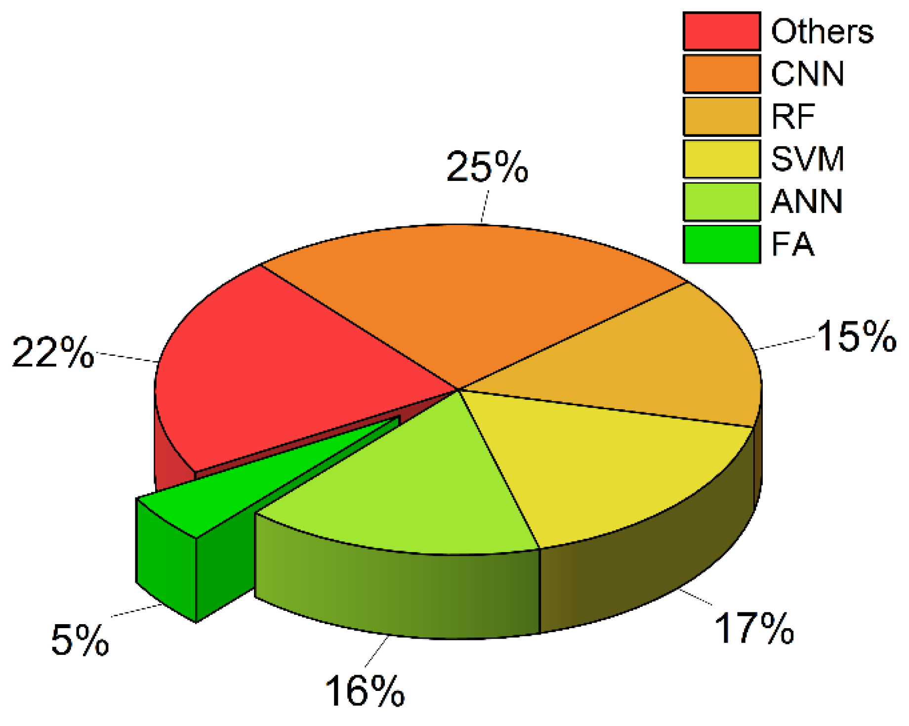
4.4. The Application of Machine Learning on Rock Mass Classification

Currently, the use of computer technology to devise predictive models has emerged as an important area of research. ML has shown proficiency in addressing geology mapping challenges and has attracted considerable attention in the geotechnical engineering field. In contrast to conventional empirical approaches, AI methods offer a superior level of precision in performing various functions. These include calculating the bearing capacity of structures, designing architectural components, forecasting the performance of tunnel boring machines (TBMs), as well as evaluating soil and rock behaviours during the tunnelling process.
As shown in Figure 2, the predominant keywords revolve around rock classification, including rocks, rock mechanics, rock mass, rock mass classification and so on. Following this, ML emerges as a notable theme, characterized by terms such as artificial intelligence, artificial neural network, algorithms, learning systems, deep learning, etc. Another recurrent keyword theme pertains to ground properties represented by lithology, geology, compressive strength, texture and rock types. In actual engineering projects, such as coal and tunnel tunnelling and mining, rock mass classification is frequently required. Moreover, in the aspects of predicting rockburst and mapping geological distribution, rock mass classification is necessary.
According to the Web of Science, there are 377 articles on rock mass identification using ML from 2002 to 2022. As can be seen in Figure 3, the adoption of ML techniques for rock mass classification has been on an upward trajectory over the past decade, with a notable increase in recent years. Predominantly utilized methods include fuzzy algorithm (FA), artificial neural networks (ANN), support vector machines (SVM), random forest (RF) and convolutional neural networks (CNN). CNN and RF have only gained popularity in recent years, whereas ANN and SVM were introduced earlier in the timeline. Each of the mentioned methods offers unique advantages. For instance, while ANN excels in capturing non-linear relationships, SVM is known for its robustness in high-dimensional spaces. At the same time, RF provides an ensemble-based approach, enhancing the accuracy of the model and preventing overfitting. CNN is adept at processing spatial hierarchies in data, making it beneficial for image-based rock texture analyses.
Figure 4 depicts the percentage of different ML methods employed in ground material identification. FA occupies the smallest portion, accounting for 5%. ANN, RF and SVM share a similar percentage, which is approximately 16%. CNN takes the largest percentage (25%), owing to its effectiveness in handling image-based material differentiation. Other methods, including clustering, transfer learning, k-nearest neighbours (KNN) and so on, collectively make up the remaining 22%.
In the realm of civil engineering, the emphasis is on analysing the mechanical properties of rock, such as the elastic modulus, uniaxial compressive strength (UCS), shear strength and rock brittleness. At the same time, the geological field primarily concentrates on lithology recognition, including igneous rocks (granite, basalt, rhyolite, andesite, etc.), sedimentary rocks (sandstone, shale, limestone, etc.) and metamorphic rocks (gneiss, marble, slate, schist, etc.). This paper focuses on the classification of rocks based on their mechanical characteristics, approached from an engineering perspective. A summarization of relevant studies from 2021 to 2022 is presented in Table 4. As can be seen, while some researchers utilize certain rock features to deduce other parameters, there are also other researchers who exploit these attributes for rock rating classifications. In addition, the application of ML in rock mechanics showcases a diverse range of input and output parameters (see Table 4). The input parameters involve a broad spectrum of rock features and testing techniques, from porosity and ultrasonic P-wave velocity (PV) to TBM operation parameters. Correspondingly, the outputs target pivotal rock properties and categorizations, with an emphasis on elements such as uniaxial compressive strength (UCS), permeability and elastic modulus. This variation underscores the multifaceted nature of research in this domain.

5. Discussion

5.1. Discussion on Empirical Approaches

Rock classification systems improve the quality of site investigations by offering a checklist of key parameters for each rock mass type. Quantified evaluation is more valuable than personal assessment as it forms a unified standard. It also facilitates effective communication of engineering judgement [79]. The main purpose of the rock classification index is predicting rock behaviours and required support systems, evaluating the stability period of unsupported spans and estimating the stand-up time of underground excavation.
In this paper, various empirical rock classification methods are reviewed and discussed. These traditional methods have served as the backbone of rock mass classification for decades, relying heavily on human experience, observational data and direct measurements. Such methods typically categorize rock masses based on their inherent characteristics, such as texture, mineral content, discontinuities and other geotechnical features. Common rock classification methods in tunnel engineering include RSR, RMR, RMI, GSI and the Q system. Among them, RMR and the Q system are regarded as versatile methods and have been applied widely for several decades in tunnel construction. Together with RSR, GSI and RMI, these empirical rock classification methods provide geotechnical engineers with preliminary information about the quality of a rock mass, which helps the initial design of a support system for geotechnical projects, such as tunnels, mines and foundations.
However, a detailed support design cannot be replaced by these empirical methods, as rock mass quality may be dominated by geological features and excavation geometry during geotechnical construction [4]. The identical methods are mainly based on visual observation; as a result, misclassification may occur in engineering applications. Additionally, in the type of rock that contains clay or other soft earth material, such as tuff, mudstone and shale, inflow of water can decrease the strength of rock mass significantly. This is not sufficiently considered in traditional rock classification systems. In fact, it is difficult to reflect the actual behaviour of a complicated rock mass by grouping it with a table. Rehman et al. [4] pointed out that there are three main challenges in applying empirical rock classification methods, including the inappropriateness of summarizing a rock mass by a single digit, the scale effect of the UCS test and rock mass identification, as well as the anisotropy and heterogeneity of underground conditions. Different rock types may correspond to a similar rating value, even if their properties are dissimilar. This leads to an increase in uncertainties and risks associated with geotechnical hazards. Empirical rock classification methods lack further approaches to deal with underground hazards, and it is difficult to evaluate the safety margin of support systems in different tunnel projects. An additional empirical classification system should be developed to predict and handle the most common hazardous failure types [80]. Meanwhile, for rock properties also relevant to other external influences, such as excavation methods, a single adjustment parameter cannot reflect its large variation scale sufficiently. Some complex rock behaviours, such as swelling and squeezing, are not covered by these empirical systems effectively [4].

5.2. Discussion on Artificial Intelligence Methods

The development of AI provides a new perspective for the evaluation of rock mass types. In tunnel engineering, using TBM operation parameters for rock mass classification is a research focus. Key parameters, such as thrust, torque and rotation speed, are used to describe correlations of geological features. The integration of ML with TBM operation parameters focuses on predicting the mechanical characteristics of rock, such as stability, drillability and hardness. The real-time identification of rock types provides guidance for TBM operation and construction strategies.
For example, Qiu et al. [77] employed specific energy, penetration rate, utilization rate, advance rate, thrust, torque and rotation speed for rock mass classification. Some optimization techniques are used, such as mean influence value (MIV) and cross validation (CV). MIV is used to select and simplify input variables, which enables a quantifiable analysis of the influence of each input variable on the outcome in ANNs. The incorporation of MIV-ANN with a CV-SVM framework shows an effective identification of rock masses. Yang et al. [81] implemented CNN and RF to differentiate competent rock and incompetent rock. Traditional methods have categorized rock masses into five grades, but Yang et al. [81] merge Grade four and five to represent incompetent rock masses and grouped the remaining grades to indicate competent rocks. Utilizing torque and the field penetration index as key input variables, this method enabled the prediction of incompetent rock mass with a high degree of accuracy. In addition, RF was developed to estimate surrounding rock properties by Liu et al. [63]. They applied statistical indicators of TBM operational parameters, including torque penetration index, field penetration index, penetration rate, rolling force, etc. For more applications employing TBM operation parameters for rock mass classification, refer to Yin et al. [82], Xue et al. [83] and so on.
An AI-driven rock mass classification system can overcome several of the challenges posed by empirical methods. Firstly, AI can process and analyse a wide range of data sources beyond visual observation. This includes geological data, seismic readings, geophysical surveys and real-time monitoring from sensors deployed in excavation sites. By incorporating such diverse data, AI models can gain a deeper understanding of the complex interplay of factors that influence rock mass behaviour, going beyond the constraints of visual inspection. Secondly, AI models can address the issue of misclassification by learning from a large dataset and continuously refining their classification criteria. This adaptability ensures that misclassifications are minimized over time, enhancing the accuracy of rock mass predictions. In addition, AI can consider external influences, such as excavation methods and their impacts on rock properties. This holistic approach enables AI to provide a more comprehensive assessment of rock mass behaviour and its response to various construction processes. For example, AI can account for the swelling and squeezing of rock mass, which are often inadequately addressed by traditional empirical systems. AI is not limited to the simplification of rock mass quality into a single rating digit. Instead, it can handle multidimensional data and recognize the nuanced variations in rock properties and behaviours. This ability to capture the intricacies of rock mass behaviour is essential for mitigating uncertainties and risks associated with geotechnical hazards. Furthermore, AI also allows for the recommendation of support methods tailored to individual tunnel projects.
Despite the considerable potential of ML in rock mass classification, it also presents several challenges that need to be addressed for its effective and reliable implementation. For example, ML requires large datasets for training and validation. Obtaining extensive, high-quality data that accurately represent various geological conditions can be challenging. In addition, geological features are inherently complex and highly variable. AI models may fail to capture this complexity fully due to inadequate or biased data. The issue of overfitting in ML models presents another risk in accurately classifying rock masses, potentially leading to poor performance and reliability in assessments. Therefore, it remains crucial to validate the obtained outcomes, ensuring that the predictions made by the ML models align with real-world observations.

5.3. Suggestions and Future Work

ML approaches should be used in conjunction with empirical methods during the whole life of geotechnical engineering construction. The results obtained from ML should be compared with manual identification for validation. While employing empirical methods, it is recommended that the characteristics of rock mass should be initially distinguished, then a rating for each parameter should be attributed and translated into different rock classification systems. At least two rock classification methods should be employed and compared. In this case, the actual behaviour of rock mass can be clearly described and accurately verified. Furthermore, it is suggested that each parameter should be evaluated with a range of values instead of a fixed number during the rock classification process. The final score of rock mass can be assessed by its significance. For instance, with an approximate score range of ‘a’ and ‘b’, where ‘a’ and ‘b’ represent the lower and upper value for the estimation of rock mass quality, the average value can be used for basic support system selection while the scope gives an indication of possible judgement.
For future work in utilizing ML for rock mass classification, the following points are proposed:
(1)
Expanding datasets: Collecting more comprehensive and diverse datasets is one of the primary areas. The accuracy of ML models depends significantly on the quality and breadth of data they are trained on. Future work could involve collaborations with geotechnical projects worldwide to create a global dataset, reflecting a broad range of geological conditions;
(2)
Integration of real-time data: As sensor technologies evolve, integrating real-time monitoring data from excavation sites into ML models could provide dynamic updates, refining rock classifications as conditions change;
(3)
Hybrid models: Combining traditional empirical evaluation methods with ML algorithms to create hybrid models can produce more accurate and reliable predictions. These models can leverage the strengths of both empirical methods and data-driven approaches;
(4)
Interdisciplinary collaborations: Collaborating with other fields, such as materials science, seismology or mineralogy, can bring fresh perspectives and techniques into the development of ML models for rock classification;
(5)
Addressing anomalies and rare events: Rare geological events or anomalies often pose significant challenges. Future ML applications should focus on techniques that detect and adapt to such rare events, ensuring reliability and robustness.
In conclusion, the introduction of AI and ML offers a new shift, promising more accurate, nuanced and comprehensive assessments of rock types. However, the integration of these technologies does not mean the abandonment of time-tested empirical methods. Instead, they should complement each other. Combining the strengths of both methodologies can ensure a more robust and reliable rock mass classification system, critical for the safety and efficiency of geotechnical projects. Additionally, establishing a large dataset that involves various rock types facilitates the training of ML, which can enhance its generalization capacity.

Author Contributions

Conceptualization, G.N. and X.H.; methodology, G.N. and H.X.; software, S.D.; validation, S.D.; investigation, G.N. and S.D.; resources, H.X.; data curation, G.N. and S.D.; writing—original draft preparation, G.N.; writing—review and editing, X.H. and H.X.; visualization, S.D.; supervision, X.H. All authors have read and agreed to the published version of the manuscript.

Funding

This paper received no external funding.

Conflicts of Interest

The authors declare no conflicts of interest.

Appendix A. Rock Structure Rating (RSR)

Table A1. Parameter A. General area geology.
Basic Rock TypeGeological Structure
HardMediumSoftDecomposed
igneous1234MassiveSlightly faulted or foldedModerately faulted or foldedIntensely faulted or folded
metamorphic1234
sedimentary2344
Type 1 3022159
Type 22720138
Type 32418127
Type 41915106
Table A2. Parameter B. Joint pattern, direction of drive.
Strike Perpendicular to AxisStrike Parallel to Axis
Drive DirectionDrive Direction
BothWith DipAgainst DipEither Direction
Dip of Prominent JointsDip of Prominent Joints
Average Joint SpacingFlatDippingVerticalDippingVerticalFlatDippingVertical
Very closely jointed, <2 ft911131012997
Closely jointed, 2–6 ft1316191517141411
Moderately jointed, 6–12 ft2324281922232319
Moderate to blocky, 1–2 ft3032362528302824
Blocky to massive, 2–4 ft3638403335362428
Massive, >4 ft4043453740403834
Note: flat: 0 20 ° ; dipping: 20 ° 50 ° ; vertical: 50 ° 90 ° .
Table A3. Parameter C. Groundwater, joint condition.
Sum of Parameter A + B
13–4445–75
Anticipated Water InflowJoint Condition
(gpm/1000 ft)GoodFairPoorGoodFairPoor
None221812252218
Slight, <200 gpm19159231914
Moderate, 200–1000 gpm15117211612
Heavy, >1000 gpm1086181410
Joint condition: good = tight or cemented; fair = slightly weathered or altered; poor = severely weathered, altered or open.

Appendix B. Rock Mass Rating (RMR)

Table A4. 1975 version of rock mass rating (RMR) system.
A. Classification parameters and their rating
1Strength of
intact rock material
Point-load strength index>8 MPa4–8 MPa2–4 MPa1–2 MPaUse of uniaxial compressive test preferred
Uniaxial compressive strength>200 MPa100–200 MPa50–100 MPa25–50 MPa10–25 MPa3–10 MPa1–3 MPa
Rating151274210
2Drill core quality RQD90–100%75–90%50–75%25–50%<25%
Rating20171383
3Spacing of joints>3 m1–3 m0.3–1 m50–300 mm<50 mm
Rating302520105
4Condition of jointsVery rough surface
Not continuous
No Separation
Hard joint wall rock
Slightly rough surfaces
Separation < 1 mm
Hard joint wall rock
Slightly rough surfaces
Separation < 1 mm
Soft joint wall rock
Slickensided surfaces
OR
Gouge < 5 mm thickness
OR
Joints open 1–5 mm Continuous joints
Soft gouge > 5 mm thick
OR
Joints open > 5 mm
Continuous joints
Rating25201260
5GroundwaterInflow per 10 m tunnel lengthNone<25 L/min25–125 L/min>125 L/min
Ratio
j o i n t w a t e r p r e s s u r e m a j o r p r i n c i p a l s t r e s s
00.0–0.20.2–0.5>0.5
General conditionsCompletely dryMoist onlyWater under moderate pressureSevere water problems
Rating10740
B. Adjustment for joint orientations
Strike and dip orientations of jointsVery favourableFavourableFairUnfavourableVery unfavourable
Ratingstunnels0−2−5−10−12
foundations0−2−7−15−25
slopes0−5−25−50−60
C. Rock mass classes and their rating
Class No.12345
DescriptionVery good rockGood rockFair rockPoor rockVery poor rock
Rating90–10070–9050–7025–50<25
Table A5. 1989 version of rock mass rating (RMR) system.
A. Classification parameters and their rating
1Strength of
intact rock material
Point-load strength index>10 MPa4–10 MPa2–4 MPa1–2 MPaUse of uniaxial compressive test preferred
Uniaxial compressive strength>200 MPa100–200 MPa50–100 MPa25–50 MPa10–25 MPa1–5 MPa<1 MPa
Rating151274210
2Drill core quality RQD90–100%75–90%50–75%25–50%<25%
Rating20171383
3Spacing of joints>2 m0.6–2 m0.2–0.6 m60–200 mm<60 mm
Rating20151085
4Condition of jointsVery rough surface
Not continuous
No Separation
Hard joint wall rock
Slightly rough surfaces
Separation < 1 mm
Hard joint wall rock
Slightly rough surfaces
Separation < 1 mm
Highly weathered wall
Slickensided surfaces
OR
Gouge < 5 mm thickness
OR
Joints open 1–5 mm Continuous joints
Soft gouge > 5 mm thick
OR
Joints open > 5 mm
Continuous joints
Rating302520100
5Ground waterInflow per 10 m tunnel lengthNone<10 L/min10–25 L/min25–125 L/min>125 L/min
Ratio
j o i n t w a t e r p r e s s u r e m a j o r p r i n c i p a l s t r e s s
0<0.10.0–0.20.2–0.5>0.5
General conditionsCompletely dryDamp Wet Dripping Flowing
Rating1510740
B. Adjustment for joint orientations
Strike and dip orientations of jointsVery favourableFavourableFairUnfavourableVery unfavourable
Ratingstunnels0−2−5−10−12
foundations0−2−7−15−25
slopes0−5−25−50−60
C. Rock mass classes and their rating
Class No.12345
DescriptionVery good rockGood rockFair rockPoor rockVery poor rock
Rating81–10061–8041–6021–40 < 20

Appendix C. Mining Rock Mass Rating (MRMR)

Figure A1. Relationship between rating adjustment and spacing in mining rock mass rating (MRMR). I means one joint set; II and III represent minimum and maximum spacing in two joint sets case; IV and V are the minimum and maximum spacing in the condition of three joint sets.
Eng 05 00012 g0a1
Table A6. Information of mining rock mass rating (MRMR) system.
UCS (MPa)RatingRQD (%)RatingJoint SpacingFracture Frequency
Average per MeterRating
1 Set2 Sets3 Sets
>1852097–100150–250.10404040
165–1851884–9614 0.15404040
145–1641671–8312 0.20404038
125–1441456–7010Details 0.25403836
105–1241244–558shown0.30383634
85–1041031–436in0.50363431
65–84817–304Figure A10.80343128
45–6464–162 1.00312826
35–4450–30 1.50282624
25–344 2.00262421
12–243 3.00242118
5–112 5.00211815
1–41 7.00181512
10.0151210
15.012107
20.01075
30.0752
40.0520
Table A7. Rock mass evaluation in mining rock mass rating (MRMR) system.
Class No.12345
DescriptionVery good rockGood rockFair rockPoor rockVery poor rock
Rating81–10061–8041–6021–40 < 20

Appendix D. Tunnelling Quality Index (Q System)

Table A8. Description of considerations and their ratings in tunnelling quality index (Q system).
DescriptionValueNote
Rock Quality Designation (RQD)
A. very poor0–25(1) where RQD is reported or measured as 10 (including 0), a nominal value of 10 is used to evaluate Q.
(2) RQD intervals of 5 is accurate.
B. poor25–50
C. fair50–75
D. good75–90
E. excellent90–100
Joint set number J n
A. massive, no or few joints0.5–1
B. one joint set2
C. one joint set plus random3
D. two joint sets4(1) for intersections use 3 × J n .
E. two joint sets plus random6
F. three joint sets9(2) for portals, use 2 × J n .
G. three joint sets plus random12
H. four or more joint sets, random,15
  heavily jointed.
J. Crushed rock, earthlike20
Joint roughness number J r
a. rock wall contact
b. rock wall contact before 10 cm shear
A. discontinuous joints4
B. rough and irregular, undulating3(1) add 1.0 if the mean spacing of the relevant
C. smooth undulating2Joint is greater than 3 m.
D. slickensided undulating1.5
E. rough or irregular, planar1.5(2) J r = 0.5 can be used for planar,
F. smooth, planar1.0slickensided joints having lineations, provided
G. slickensided, planar0.5that the lineations are oriented for minimum
c. no rock wall contact when sheared strength.
H. zones containing clay minerals thick1.0
 enough to prevent rock wall contact(nominal)
J. sandy, gravely or crushed zone thick1.0
 enough to prevent rock wall contact(nominal)
Joint alteration number J a
a. rock wall contact φ (degrees)
A. tightly healed, hard, non-softening,0.75
 impermeable filling
B. unaltered joint walls, surface 1.025–35
 staining only
C. slightly altered joint walls, non-2.025–30
 softening mineral coating, sandy
 particles, clay-free disintegrated
 rock, etc.
D. silty or sandy clay coatings, small3.020–25
 clay fraction (non-softening)
E. softening or low-fraction clay 4.08–16
 mineral coatings, i.e., kaolinite, mica, (1) values of φ , the residual
 chlorite, talc, gypsum, graphite, friction angle, are intended as
 etc. and small quantities of swelling approximate guide to the
 clays (discontinuous coatings, 1–2 mineralogical properties of
 mm or less in thickness) the alteration products, if
b. rock wall contact before 10 cm shear present.
F. sandy particles, clay-free, 4.025–30
 disintegrating rock, etc.
G. strongly overconsolidated, non-6.016–24
 softening clay mineral fillings
H. medium or low overconsolidation,8.012–16
 softening clay mineral fillings
I. swelling clay fillings, i.e., 8.0–12.06–12
 montmorillonite. Values of J a
 depend on percent of swelling
 clay-size particles and access to
 water
c. no rock wall contact when sheared
J. zones or bands of disintegrated6.0 or 8.0–12.06–24
 or crushed rock and clay
K. zones or bands of silty or sandy clay5.0
 small clay fraction (non-softening)
L. Thick, continuous zones or bands10.0 or 13.0–20.06–24
 of clay
Joint water reduction number J w
water pressure ( k g / m 2 )
A. dry excavations or minor inflow,1.0<1
 i.e., <5 L/min locally
B. medium inflow or pressure, 0.661.0–2.5(1) factors C to F are crude
 occasional outwash of joint fillings estimates; increase J w if
C. large inflow or high pressure in0.5 drainage installed.
 competent rock with unfilled joints
D. large inflow or high pressure, 0.332.5–10.0
 considerable outwash of joint filling
E. exceptionally high inflow or water0.2–0.1>10.0(2) special problems caused
 pressure at blasting, decaying by ice formation are not
 with time considered.
F. exceptionally high inflow or water0.1–0.05>10.0
 pressure continuing without
 noticeable decay
Stress reduction factor (SRF)
a. weakness zones intersecting excavation, which may cause loosening of rock mass when tunnel is excavated
A. multiple occurrences of weakness 10.0
 zones containing clay or chemically
 disintegrated rock, very loose
 surrounding rock (any depth)
B. single weakness zone containing 5.0
 clay or chemically disintegrated
 rock (excavation depth < 50 m)
C. single weakness zone containing 2.5(1) reduce these values of SRF by 25–50%
 clay or chemically disintegrated but only if the relevant shear zone’s influence
 rock (excavation depth > 50 m) does not intersect the excavation.
D. multiple shear zones in competent 7.5
 rock (clay free), loose surrounding
 rock (any depth)
E. single shear zone in competent rock5.0
 (clay-free) (excavation depth < 50 m)
F. single shear zone in competent rock2.5
 (clay-free) (excavation depth > 50 m)
G. loose open joints, heavily jointed or5.0
 ‘sugar cube’, etc. (any depth)
b. competent rock, rock stress problem σ c / σ 1 σ t / σ 1
H. low stress, near surface>200>132.5(2) for strongly anisotropic
J. medium stress200–1013–0.661.0virgin stress field: when
K. high stress, very tight structure10–50.66–0.330.5–2 5 σ c / σ 1 10 , reduce σ c
 (usually favourable to stability, may to 0.8 σ c and σ t to 0.8 σ t .
 be unfavourable to wall stability) When σ c / σ 1 > 10 , reduce σ c
L. mild rockburst (massive rock)5–2.50.33–0.165–10to 0.6 σ c and σ t to 0.6 σ t .
M. heavy rockburst (massive rock)<2.5<0.1610–20
c. squeezing rock, plastic flow of incompetent rock under the influence of high rock pressure
N. mild squeezing rock pressure 5–10(3) few case records available
O. heavy squeezing rock pressure 10–20where depth of crown below
d. swelling rock, chemical swelling activity depending on presence of watersurface is less than span
P. mild squeezing rock pressure 5–10width. Suggest increase SRF
R. heavy squeezing rock pressure 10–15from 2.5 to 5 in such a case.
σ c is unconfined compressive strength; σ t is tensile strength (point load); σ 1 and σ 3 are the major and minor principal stresses separately.

Appendix E. Rock Mass Index (RMI)

Table A9. Considerations and ratings of rock mass index (RMI) system.
Uniaxial compressive strength ( U C S ) (MPa)Obtained from experimental tests or assumed from handbook
Block volume ( V b ) ( m 3 )Obtained from observation at site or drill cores
Joint condition factor ( J C )   = J R × J A × J L J R ,   J A   a n d   J L are determined from tables below
Joint roughness factor ( J R ) Large-scale waviness of joint plane
PlanarSlightly undulatingUndulating Strongly undulatingStepped or interlocking
Small scale smoothness of joint surfaceVery rough2.03.04.06.06.0
Rough1.52.03.04.56.0
Smooth1.01.52.03.04.0
Polished0.51.01.52.03.0
Slickenside0.51.01.52.03.0
for filled joints J R = 1 , for irregular joints J R = 6
Joint alteration factor ( J A )
Contact between joint wallsClean jointsHealed or welded jointsFilling of quartz, epidote, etc.0.75
Fresh joint wallsNo coating or filling1.0
Altered joint wallsOne grade higher alteration2.0
Two grades higher alteration4.0
Coating or thin filling Frictional materialsSand, silt calcite, etc.3.0
Cohesive materialsClay, chlorite, talc, etc.4.0
Partly or no wall contactThick filling Thin ( < 5 m m ) Thick
Frictional materialsSand, silt chlorite, etc.48
Hard, cohesive materialsClay, chlorite, talc, etc.65–10
Soft, cohesive materialsClay, chlorite, talc, etc.812
Swelling clay materialsSwelling behaviour material8–1213–20
Joint size factor ( J L )
continuousdiscontinuous
Bedding or foliation partingsLength < 5 m 3.06.0
Joints Length 0.1–1 m2.04.0
Length 1–10 m1.02.0
Length 10–30 m0.751.5
Filled joint, seam or shear (special cases)Length > 30 m 0.51.0

References

  1. Spross, J.; Stille, H.; Johansson, F.; Palmstrøm, A. Principles of Risk-Based Rock Engineering Design. Rock Mech. Rock Eng. 2019, 53, 1129–1143. [Google Scholar] [CrossRef]
  2. Bieniawski, Z.T. Engineering Rock Mass Classification: A Complete Manual for Engineers and Geologists in Mining, Civil and Petroleum Engineering; John Wiley & Sons: Hoboken, NJ, USA, 1989. [Google Scholar]
  3. Aksoy, C.O. Review of rock mass rating classification: Historical developments, applications, and restrictions. J. Min. Sci. 2008, 44, 51–63. [Google Scholar] [CrossRef]
  4. Rehman, H.; Ali, W.; Naji, A.M.; Kim, J.-J.; Abdullah, R.A.; Yoo, H.-K. Review of rock-mass rating and tunneling quality index systems for tunnel design: Development, refinement, application and limitation. Appl. Sci. 2018, 8, 1250. [Google Scholar] [CrossRef]
  5. Harrison, J.P.; Hudson, J.A. Engineering Rock Mechanics Part II; Elsevier: Amsterdam, The Netherlands, 2000. [Google Scholar]
  6. Li, M.; Li, K.; Qin, Q. A rockburst prediction model based on extreme learning machine with improved Harris Hawks optimization and its application. Tunn. Undergr. Space Technol. 2023, 134, 104978. [Google Scholar] [CrossRef]
  7. Jin, A.; Basnet, P.M.S.; Mahtab, S. Microseismicity-based short-term rockburst prediction using non-linear support vector machine. Acta Geophys. 2022, 70, 1717–1736. [Google Scholar] [CrossRef]
  8. Pu, Y.; Apel, D.B.; Liu, V.; Mitri, H. Machine learning methods for rockburst prediction-state-of-the-art review. Int. J. Min. Sci. Technol. 2019, 29, 565–570. [Google Scholar] [CrossRef]
  9. Xue, Y.; Bai, C.; Qiu, D.; Kong, F.; Li, Z. Predicting rockburst with database using particle swarm optimization and extreme learning machine. Tunn. Undergr. Space Technol. 2020, 98, 103287. [Google Scholar] [CrossRef]
  10. Azarafza, M.; Bonab, M.H.; Derakhshani, R. A Deep Learning Method for the Prediction of the Index Mechanical Properties and Strength Parameters of Marlstone. Materials 2022, 15, 6899. [Google Scholar] [CrossRef]
  11. Deere, D.U.; Hendron, A.J.; Patton, F.D.; Cording, E.J. Design of Surface and Near Surface Construction in Rock. In Proceedings of the 8th U.S. Symposium on Rock Mechanics (USRMS), Minneapolis, MN, 15–17 September 1966; pp. 237–302. [Google Scholar]
  12. Palmstrom, A. The volumetric joint count-a useful and simple measure of the degree of rock jointing. In Proceedings of the 4th International Congress, International Association of Engineering Geology, Delhi, India, 10–15 December 1982; pp. 221–228. [Google Scholar]
  13. Priest, S.; Hudson, J. Discontinuity spacings in rock. Int. J. Rock Mech. Min. Sci. Géoméch. Abstr. 1976, 13, 135–148. [Google Scholar] [CrossRef]
  14. Van Der, S. Block punch index test: Van der Schrier, J S Int Assoc Engng Geol BullN38, Oct 1988, P121–126. Int. J. Rock Mech. Min. Sci. Geomech. Abstr. 1989, 26, A112. [Google Scholar] [CrossRef]
  15. Ulusay, R.; Gokceoglu, C. The modified block punch index test. Can. Geotech. J. 1997, 34, 991–1001. [Google Scholar] [CrossRef]
  16. Aydin, A.; Basu, A. The Schmidt hammer in rock material characterization. Eng. Geol. 2005, 81, 1–14. [Google Scholar] [CrossRef]
  17. Li, B.X.; Rupert, G.; Summers, D.A.; Santi, P.; Liu, D. Analysis of Impact Hammer Rebound to Estimate Rock Drillability. In Rock Mechanics and Rock Engineering; Springer: Berlin/Heidelberg, Germany, 2000. [Google Scholar]
  18. Sheorey, P.; Barat, D.; Das, M.; Mukherjee, K.; Singh, B. Schmidt Hammer Rebound Data for Estimation of Large Scale In Situ Coal Strength. Int. J. Rock Mech. Min. Sci. Géoméch. Abstr. 1984, 21, 39–42. [Google Scholar] [CrossRef]
  19. Saptono, S.; Kramadibrata, S.; Sulistianto, B. Using the Schmidt Hammer on Rock Mass Characteristic in Sedimentary Rock at Tutupan Coal Mine. Procedia Earth Planet. Sci. 2013, 6, 390–395. [Google Scholar] [CrossRef]
  20. Fattahi, H. Applying soft computing methods to predict the uniaxial compressive strength of rocks from schmidt hammer rebound values. Comput. Geosci. 2017, 21, 665–681. [Google Scholar] [CrossRef]
  21. Wickham, G.; Tiedemann, H.R.; Skinner, E.H. Support determinations based on geologic predictions: 3F, 8T, 13R. PROCEEDINGS RETC. AIMMPE, NEW YORK, USA, V1, 1972, P43–P64. Int. J. Rock Mech. Min. Sci. Geomech. Abstr. 1975, 12, 95. [Google Scholar] [CrossRef]
  22. Bieniawski, Z.T. Engineering classification of jointed rock masses. Civ. Eng. S. Afr. 1973, 15, 333–343. [Google Scholar]
  23. Kendorski, F.; Cummings, R.; Bieniawski, Z.T.; Skinner, E. Rock mass classification for block caving mine drift support. In Proceedings of the 5th International Society for Rock Mechanics, Melbourne, Australia, 10–15 April 1983; pp. B51–B63. [Google Scholar]
  24. Laubscher, D.H. Design aspects and effectiveness of support systems in different mining conditions. Trans.-Inst. Min. Metall. Sect. A 1984, 93, A70–A82. [Google Scholar]
  25. Laubscher, D.M.; Page, C.H. The design of rock support in high stress or weak rock environments. In Proceedings of the 92nd Canadian Institute of Mining and Metallurgy, Ottawa, ON, Canada, 6–10 May 1990. [Google Scholar]
  26. Barton, N.R.; Lien, R.; Lunde, J. Engineering classification of rock masses for the design of tunnel project. Rock Mech. 1974, 6, 189–238. [Google Scholar] [CrossRef]
  27. Palmstrom, A.; Broch, E. Use and misuse of rock mass classification systems with particular reference to the Q-system. Tunn. Undergr. Space Technol. 2006, 21, 575–593. [Google Scholar] [CrossRef]
  28. Palmstrom, A.; Stille, H. Ground behaviour and rock engineering tools for underground excavations. Tunn. Undergr. Space Technol. 2007, 22, 363–376. [Google Scholar] [CrossRef]
  29. Goel, R.; Jethwa, J.; Paithankar, A. Indian experiences with Q and RMR systems. Tunn. Undergr. Space Technol. 1995, 10, 97–109. [Google Scholar] [CrossRef]
  30. Schwingenschloegl, R.; Lehmann, C. Swelling rock behaviour in a tunnel: NATM-support vs. Q-support—A comparison. Tunn. Undergr. Space Technol. 2009, 24, 356–362. [Google Scholar] [CrossRef]
  31. Hussian, S.; Mohammad, N.; Ur Rehman, Z.; Khan, N.M.; Shahzada, K.; Ali, S.; Tahir, M.; Raza, S.; Sherin, S. Review of the geological strength index (GSI) as an empirical classification and rock mass property estimation tool: Origination, modifications, applications, and limitations. Adv. Civ. Eng. 2020, 2020, 6471837. [Google Scholar] [CrossRef]
  32. Palmstrom, A. A Rock Mass Characterization System for Rock Engineering Purposes. Ph.D. Thesis, University of Oslo, Oslo, Norway, 1995. [Google Scholar]
  33. Hoek, E.; Wood, D.; Shah, S. A modified Hoek–Brown failure criterion for jointed rock masses. In Proceedings of the Rock Characterization: ISRM Symposium, Eurock ‘92, Chester, UK, 14–17 September 1992; pp. 209–214. [Google Scholar]
  34. Khamehchiyan, M.; Dizadji, M.R.; Esmaeili, M. Application of rock mass index (RMi) to the rock mass excavatability assessment in open face excavations. Géoméch. Geoengin. 2013, 9, 63–71. [Google Scholar] [CrossRef]
  35. Palmstrom. Characterizing rock masses by the RMi for Use in Practical Rock Engineering. Tunn. Undergr. Space Technol. 1996, 11, 175–188. [Google Scholar] [CrossRef]
  36. Hoek, E.; Kaiser, P.K.; Bawden, W.F. Support of Underground Excavations in Hard Rock; CRC Press: Boca Raton, FL, USA, 1993. [Google Scholar]
  37. Marinos, V.; Marinos, P.; Hoek, E. The geological strength index: Applications and limitations. Bull. Eng. Geol. Environ. 2005, 64, 55–65. [Google Scholar] [CrossRef]
  38. Russo, A.; Hormazabal, E. Correlations Between Various Rock Mass Classification Systems, Including Laubscher (MRMR), Bieniawski (RMR), Barton (Q) and Hoek and Marinos (GSI) Systems. In Geotechnical Engineering in the XXI Century: Lessons Learned and Future Challenges; IOS Press: Amsterdam, The Netherlands, 2019. [Google Scholar]
  39. Cai, M.; Kaiser, P.K.; Tasaka, Y.; Minami, M. Peak and residual strengths of jointed rock masses and their determination for engineering design. In Proceedings of the 1st Canada-US Rock Mechanics Symposium-Rock Mechanics Meeting Society’s Challenges and Demands, Vancouver, BC, Canada, 27–31 May 2007; Volume 1, pp. 259–267. [Google Scholar] [CrossRef]
  40. Cai, M.; Kaiser, P.; Uno, H.; Tasaka, Y.; Minami, M. Estimation of rock mass deformation modulus and strength of jointed hard rock masses using the GSI system. Int. J. Rock Mech. Min. Sci. 2003, 41, 3–19. [Google Scholar] [CrossRef]
  41. Hoek, E.; Carter, T.G.; Diederichs, M.S. Quantification of the Geological Strength Index Chart. In Proceedings of the 47th U.S. Rock Mechanics/Geomechanics Symposium, San Francisco, CA, USA, 23–26 June 2013. [Google Scholar]
  42. Brown, E. Estimating the Mechanical Properties of Rock Masses. In Proceedings of the First Southern Hemisphere International Rock Mechanics Symposium, Australian Centre for Geomechanics, Perth, Australia, 16–19 September 2008; pp. 3–22. [Google Scholar] [CrossRef]
  43. Bieniawski, Z.T. Rock mass classification in rock engineering. In Engineering Rock Mass Classifications: A Complete Manual for Engineers and Geologists in Mining, Civil, and Petroleum Engineering; Wiley-Interscience: Hoboken, NJ, USA, 1976; pp. 97–106. [Google Scholar]
  44. Rutledge, J.C.; Preston, R.L. Experience with engineering classifications of rock. In Proceedings of the International Tunnel Symposium, Tokyo, Japan, 29 May–2 June 1978; pp. A3.1–A3.7. [Google Scholar]
  45. Cameron Clarke, L.S.; Budavari, S. Correction of Rock Mass Classification Parameters Obtained from Borecore and In Situ Observations; Engineering Geology; Elsevier: Amsterdam, The Netherlands, 1981; Volume 17. [Google Scholar]
  46. Moreno Tallon, E. Comparison and application of geomechanics classification schemes in tunnel construction. In Proceedings of the 3rd International Symposium, Brighton, UK, 7–11 June 1982; pp. 241–246. [Google Scholar]
  47. Abad, J.; Celad, B.; Chacon, E.; Gutierrez, V.; Hidalgo, E. Application of geomechanical classification to predict the convergence of coal mine galleries and to design their supports. In Proceedings of the 5th International Society for Rock Mechanics, Melbourne, Australia, 10–15 April 1983; pp. E15–E19. [Google Scholar]
  48. Baczynski, N.R.P. Application of various rock mass classification to unsupported openings at Mount Isa Queensland: A case study. In Proceedings of the Third Australia-New Zealand conference on Geomechanics, Wellington, New Zealand, 12–16 May 1980; pp. 137–143. [Google Scholar]
  49. Celada Thamames, B. Fourteen years of experience on rock bolting in Spain. In Proceedings of the International Symposium on Rock Bolting, Abisko, Sweden, 28 August–2 September 1983. [Google Scholar]
  50. Udd, J.E.; Wang, H.A. A comparison of some approaches to the classification of rock maaes for geotechnical purposes. In Proceedings of the 26th U.S. Symposium on Rock Mechanics (USRMS), Rapid City, South Dakota, 26–28 June 1985. [Google Scholar]
  51. Kaiser, P.K.; Mackay, C.; Gale, A.D. Evaluation of rock classification at B. C. Rail Tumbler Ridge Tunnels. In Rock Mechanics and Rock Engineering; Springer: Berlin/Heidelberg, Germany, 1986; Volume 19, pp. 205–234. [Google Scholar]
  52. Choquet, P.; Charette, F. Applicability of rock mass classification in the design of rock support in mines. In Proceedings of the 15th Canadian Rock Mechanics Symposium, Toronto, ON, Canada, 3–4 October 1988. [Google Scholar]
  53. Sheorey, P.R. Experience with the application of modern rock classifications in coal mine roadways. In Comprehensive Rock Engineering, Principles, Practice and Projects; Elsevier: Amsterdam, The Netherlands, 1993. [Google Scholar]
  54. Rawlings, C.G.; Barton, N.; Smallwood, A.; Davies, N. Rock mass characterisation using the Q and RMR systems. In Proceedings of the 8th International Society for Rock Mechanics, Tokyo, Japan, 25–29 September 1995. [Google Scholar]
  55. Tuǧrul, A.T. The application of rock mass classification systems to underground excavation in weak limestone, Atatü rk dam, Turkey. Eng. Geol. 1998, 50, 337–345. [Google Scholar] [CrossRef]
  56. Asgari, A.R. New correction between “Q & RMR” and “N & RCR”. In Proceedings of the 5th Iranian Tunnelling Conference, Tehran, Iran; 2001. [Google Scholar]
  57. Sunwoo, C.; Hwang, S. Correction of rock mass classification methods in Korean rock mass. In Proceedings of the ISRM International Symposium—2nd Asian Rock Mechanics Symposium, Beijing, China, 11–14 September 2001. [Google Scholar]
  58. Kumar, N.; Samadhiya, N.K.; Anbalagan, R. Application of rock mass classification systems for tunneling in Himalaya, India. Int. J. Rock Mech. Min. Sci. 2004, 41 (Suppl. 1), 852–857. [Google Scholar] [CrossRef]
  59. Sari, D.; Pasamehmetoglu, A. Proposed support design, Kaletepe tunnel, Turkey. Eng. Geol. 2003, 72, 201–216. [Google Scholar] [CrossRef]
  60. Laderian, A.; Abaspoor, M.A. The correlation between RMR and Q systems in parts of Iran. Tunn. Undergr. Space Technol. 2012, 27, 149–158. [Google Scholar] [CrossRef]
  61. Sayeed, I.; Khanna, R. Empirical Correlation between RMR and Q Systems of Rock Mass Classification Derived from Lesser Himalayan and Central Crystalline Rocks. 2015. Available online: https://www.researchgate.net/publication/283497675 (accessed on 15 June 2023).
  62. Soufi, A.; Bahi, L.; Ouadif, L.; Kissai, J.E. Correlation between Rock mass rating, Q-system and Rock mass index based on field data. MATEC Web Conf. 2018, 149, 02030. [Google Scholar] [CrossRef]
  63. Liu, Q.; Wang, X.; Huang, X.; Yin, X. Prediction model of rock mass class using classification and regression tree integrated AdaBoost algorithm based on TBM driving data. Tunn. Undergr. Space Technol. 2020, 106, 103595. [Google Scholar] [CrossRef]
  64. Hou, S.K.; Liu, Y.R.; Li, C.Y.; Qin, P.X. Dynamic Prediction of Rock Mass Classification in the Tunnel Construction Process based on Random Forest Algorithm and TBM In Situ Operation Parameters. IOP Conf. Ser. Earth Environ. Sci. 2020, 570, 052056. [Google Scholar] [CrossRef]
  65. Sun, D.; Lonbani, M.; Askarian, B.; Armaghani, D.J.; Tarinejad, R.; Pham, B.T.; Van Huynh, V. Investigating the Applications of Machine Learning Techniques to Predict the Rock Brittleness Index. Appl. Sci. 2020, 10, 1691. [Google Scholar] [CrossRef]
  66. Barzegar, R.; Sattarpour, M.; Deo, R.; Fijani, E.; Adamowski, J. An ensemble tree-based machine learning model for predicting the uniaxial compressive strength of travertine rocks. Neural Comput. Appl. 2019, 32, 9065–9080. [Google Scholar] [CrossRef]
  67. Gül, E.; Ozdemir, E.; Sarıcı, D.E. Modeling uniaxial compressive strength of some rocks from turkey using soft computing techniques. Meas. J. Int. Meas. Confed. 2020, 171, 108781. [Google Scholar] [CrossRef]
  68. Sun, Y.; Li, G.; Zhang, J.; Huang, J. Rockburst intensity evaluation by a novel systematic and evolved approach: Machine learning booster and application. Bull. Eng. Geol. Environ. 2021, 80, 8385–8395. [Google Scholar] [CrossRef]
  69. Santos, A.E.M.; Lana, M.S.; Pereira, T.M. Rock Mass Classification by Multivariate Statistical Techniques and Artificial Intelligence. Geotech. Geol. Eng. 2020, 39, 2409–2430. [Google Scholar] [CrossRef]
  70. Köken, E.; Koca, T.K. Evaluation of Soft Computing Methods for Estimating Tangential Young Modulus of Intact Rock Based on Statistical Performance Indices. Geotech. Geol. Eng. 2022, 40, 3619–3631. [Google Scholar] [CrossRef]
  71. Alizadeh, S.M.; Iraji, A. Application of soft computing and statistical methods to predict rock mass permeability. Soft Comput. 2022, 27, 5831–5853. [Google Scholar] [CrossRef]
  72. Koca, T.K.; Köken, E. A combined application of two soft computing algorithms for weathering degree quantification of andesitic rocks. Appl. Comput. Geosci. 2022, 16, 100101. [Google Scholar] [CrossRef]
  73. Rahman, T.; Sarkar, K. Estimating strength parameters of Lower Gondwana coal measure rocks under dry and saturated conditions. J. Earth Syst. Sci. 2022, 131, 175. [Google Scholar] [CrossRef]
  74. Fathipour-Azar, H. Stacking Ensemble Machine Learning-Based Shear Strength Model for Rock Discontinuity. Geotech. Geol. Eng. 2022, 40, 3091–3106. [Google Scholar] [CrossRef]
  75. Santos, A.E.M.; Lana, M.S.; Pereira, T.M. Evaluation of machine learning methods for rock mass classification. Neural Comput. Appl. 2021, 34, 4633–4642. [Google Scholar] [CrossRef]
  76. Tsang, L.; He, B.; A Rashid, A.S.; Jalil, A.T.; Sabri, M.M.S. Predicting the Young’s Modulus of Rock Material Based on Petrographic and Rock Index Tests Using Boosting and Bagging Intelligence Techniques. Appl. Sci. 2022, 12, 10258. [Google Scholar] [CrossRef]
  77. Qiu, D.; Fu, K.; Xue, Y.; Tao, Y.; Kong, F.; Bai, C. TBM Tunnel Surrounding Rock Classification Method and Real-Time Identification Model Based on Tunneling Performance. Int. J. Géoméch. 2022, 22, 04022070. [Google Scholar] [CrossRef]
  78. Hou, S.; Liu, Y.; Yang, Q. Real-time prediction of rock mass classification based on TBM operation big data and stacking technique of ensemble learning. J. Rock Mech. Geotech. Eng. 2022, 14, 123–143. [Google Scholar] [CrossRef]
  79. Hoek, E.; Diederichs, M.S. Empirical estimation of rock mass modulus. Int. J. Rock Mech. Min. Sci. 2006, 43, 203–215. [Google Scholar] [CrossRef]
  80. Pantelidis, L. Rock slope stability assessment through rock mass classification systems. Int. J. Rock Mech. Min. Sci. 2009, 46, 315–325. [Google Scholar] [CrossRef]
  81. Yang, W.; Zhao, J.; Li, J.; Chen, Z. Probabilistic machine learning approach to predict incompetent rock masses in TBM construction. Acta Geotech. 2023, 18, 4973–4991. [Google Scholar] [CrossRef]
  82. Yin, X.; Liu, Q.; Huang, X.; Pan, Y. Perception model of surrounding rock geological conditions based on TBM operational big data and combined unsupervised-supervised learning. Tunn. Undergr. Space Technol. 2022, 120, 104285. [Google Scholar] [CrossRef]
  83. Xue, Y.-D.; Luo, W.; Chen, L.; Dong, H.-X.; Shu, L.-S.; Zhao, L. An intelligent method for TBM surrounding rock classification based on time series segmentation of rock-machine interaction data. Tunn. Undergr. Space Technol. 2023, 140, 105317. [Google Scholar] [CrossRef]
Figure 1. Description and calculation process of rock quality designation (RQD).
Eng 05 00012 g001
Figure 2. Keywords when employing ML for rock mass classification.
Eng 05 00012 g002
Figure 3. The tendency of rock mass classification through ML method.
Eng 05 00012 g003
Figure 4. Application of different ML methods in geotechnical identification.
Eng 05 00012 g004
Table 1. Advantages and disadvantages of different RQD techniques.
MethodsAdvantagesLimitations
Core logging1. Widely accepted and standardized, making it a common approach;1. Lacks sensitivity in highly fractured and weathered rock;
2. Easy to calculate;2. Fails to consider the orientation of joints;
3. Useful for quick assessment of rock quality and correlating with other rock mass classification systems.3. Can be influenced by dilling operations and equipment quality.
J v method from Palmstrom [12]1. Provides a more comprehensive understanding of rock mass, including fracture properties;1. Requires detailed field data, which means it is complex and time costing.
2. More accurate in heterogeneous or highly jointed rock masses.
λ method from Priest and Hudson [13]1. Offers simple measurement of joint frequency, providing clear data on one aspect of rock mass behaviour;1. Does not consider the joint orientation or other aspects of rock mass, such as infill materials;
2. Useful in preliminary design stages.2. It is not sufficient for detailed design work.
Table 2. Considered factors and their ratings in different versions of the RMR system.
ParameterYear
197319741975197619791989201120132014
UCS0–100–100–150–150–150–150–150–150–15
RQD3–163–203–203–203–203–200–20----
JS5–305–305–305–305–205–200–20----
DD--------------0–400–40
S1–5----------------
CJ0–5----------------
W1–9----------------
JC--0–150–250–250–300–300–300–300–20
GW2–102–100–100–100–150–150–150–150–15
A----------------0–10
F o 3–153–150–(−12)0–(−12)0–(−12)0–(−12)0–(−12)0–(−12)0–(−12)
F e ----------------1–1.32
F s ----------------1–1.3
UCS means uniaxial compressive strength of intact rock (MPa); RQD is rock quality designation (%), JS means joint spacing (mm); DD means discontinuity density (joints per meter); S means separation of joints (mm); CJ means continuity of joints (m), W means weathering level; JC is condition of joints; GW is groundwater situation; A is alterability (%), F o ,   F e ,   F s are adjustment parameters.
Table 3. Review of the relationship between RMR and Q value.
FormulaDescriptionReference
R M R = 9 l n Q + 44 --[43]
R M R = 5.9 l n Q + 43 R M R = 13.3 l o g Q + 43 [44]
R M R = 5 l n Q + 60.8 From in situ data[45]
R M R = 4.6 l n Q + 55.5 From bore core data[45]
R M R = 5.4 l n Q + 55.2 R M R = 12.5 l o g Q + 55.2 [46]
R M R = 10.5 l n Q + 41.8 --[47]
R M R = 7.5 l n Q + 42 --[48]
R M R = 9.19 l n Q + 43.89 --[49]
R M R = 5.3 l n Q + 50.81 R M R = 12.11 l o g Q + 50.81 [50]
R M R = 6.3 l n Q + 41.6 --[51]
R M R = 8.7 l n Q + 38 ± 18 Probability theory[51]
R M R = 10 l n Q + 39 --[52]
R M R = 6.8 l n Q + 42 --[53]
R M R = 10.3 l n Q + 49.3 Q 1 ,   S R F = 1 [54]
R M R = 6.2 l n Q + 49.2 Q > 1 ,   S R F = 1 [54]
R M R = 6.6 l n Q + 53 Q 0.65 [54]
R M R = 5.7 l n Q + 54.1 Q > 0.65 [54]
R M R = 7 l n Q + 36 --[55]
R M R = 4.2 l n Q + 50.6 --[56]
R M R = 5.97 l n Q + 49.5 --[57]
R M R = 4.7 l n Q + 56.8 --[58]
R M R = 8.3 l n Q + 42.5 S R F = 1 [58]
R M R = 6.4 l n Q + 49.6 Revised S R F values[58]
R M R = 3.7 l n Q + 53.1 --[59]
R M R = 8.15 l n Q + 44.88 --[60]
R M R = 42.87 Q 0.162 --[60]
R M R = 4.52 l n Q + 43.6 --[61]
R M R = 5.614 l n Q + 49.39 --[62]
Table 4. Publications of ML-based rock mass classification and property prediction within past three years.
ML MethodDatasetInputOutputReference
UCSBTSPVnρOthers
RF3166 TBM parameters (penetration rate, rotation speed, etc.)rock mass class[63]
RF7538 TBM parameters (penetration rate, rotation speed, etc.)rock mass class[64]
RF110 Schmidt hammer rebound number, point load indexrock brittleness index[65]
ANN93 Schmidt hammer rebound number, point load indexUCS[66]
ANN30 shore hardnessUCS[67]
RF279 depth, tangential stress, elastic strain energy indexrockburst intensity[68]
ANN3210 weathering condition, fracture degree, water conditionRMR rating[69]
ANFIS147 --E[70]
SVM175 depth, Q-system rating, joint spacing, Lugeon numberpermeability[71]
ANN182 --weathering degree[72]
ANN81rock typesUCS, BTS, PV[73]
RF168 normal stress, joint roughness coefficientG[74]
ANN120 c, E, G, φUCS, c, E, G, φ[10]
RF3216 weathering condition, discontinuities condition, water conditionRMR rating[75]
RF45 interlocking coarse-grained crystals of quartz, mica contentE[76]
SVM441 TBM parameters (advance rate, specific energy)Q-system rating[77]
RF7538 TBM parameters (penetration rate, rotation speed, etc.) rock mass class[78]
BTS means Brazilian tensile strength, UCS means uniaxial compression strength; PV means ultrasonic P wave velocity; ρ means density; n means porosity; E means elastic modulus; G means shear modulus; c means cohesion; φ means friction angle.
Disclaimer/Publisher’s Note: The statements, opinions and data contained in all publications are solely those of the individual author(s) and contributor(s) and not of MDPI and/or the editor(s). MDPI and/or the editor(s) disclaim responsibility for any injury to people or property resulting from any ideas, methods, instructions or products referred to in the content.

