
Far-Field Radiation Characteristics of Folded Monopole Antennas over a Conducting Ground Plane


Department of Engineering, University of Southern Maine, Gorham, ME 04038, USA
Eng 2022, 3(1), 142-160; https://doi.org/10.3390/eng3010012
Submission received: 30 November 2021
/
Revised: 24 February 2022
/
Accepted: 1 March 2022
/
Published: 9 March 2022
(This article belongs to the Section Electrical and Electronic Engineering)
Abstract
:Folded monopole structures have been used for many applications, including low-frequency electromagnetic wave transmission and reception. However, the literature on these antenna types is quite limited. Folded monopole antennas are mathematically complex compared to conventional monopole or dipole antennas since every fold introduces a new set of design parameters. This work studied the far-field radiation characteristics of multi-folded monopole antennas operating at 75 MHz in terms of their radiated power concerning the frequency, the far-field directivity of the electric field, and the effect of each design parameter on the far-field radiation power. According to the results, folding a monopole antenna multiple times increases its effective length, making this antenna a suitable candidate for applications where the antenna height is restricted. Additionally, the ground-to-wire separation has the biggest effect on radiated power. In both single-fold and two-fold cases, doubling the ground-to-wire separation increased the radiated power by 0.2 W compared to the other models with the same number of folds. As for the challenges, the impedance mismatch between the source and antenna causes a significant amount of power reflection; hence, suitable impedance matching is required to reduce reflected power.
1. Introduction
It is well known in electrical engineering that the dimensions of an antenna should be comparable to the wavelength of the resonance signal. Based on this principle, there is a wide range of antennas designed starting from single monopoles, dipoles, loop antennas, and microstrip antennas [1,2,3], to name a few, and the dimensions of these are factors of the signal wavelengths of interest (quarter-wave, half-wave, etc.). With improvements in technology, people have accessed higher and higher frequencies, making the wavelengths they are dealing with smaller. As a result, within the last few decades, all electromagnetic applications became miniaturized. With this size reduction, all electromagnetic instruments—most importantly, cell phones—became very compact devices. The dimensionality challenge comes when it comes to dealing with low frequencies. For example, very low-frequency (VLF: 3–30 kHz) signals have wavelengths in the order of hundreds of kilometers [4,5,6,7,8,9]. Additionally, in the field of biomedical applications, it is a frequent challenge to build an antenna that matches the required wavelength while maintaining sufficient directivity.
In the area of low-frequency communications, there is a type of antenna known as the folded monopole or the folded unipole. This was introduced to increase the effective length of the antenna by folding it. In the basic folded monopole configuration, the portion of the wire connected to the source of the feed is known as the fold and the conductor that carries the return current is known as a tower [10,11,12]. The ratio of the fold and tower radii is a major determinant of the characteristic impedances and the bandwidth of the antenna. Folded antennas introduce additional design variables, such as fold and tower radii, fold and tower lengths, and external loads for different modes of operation, which will be discussed in the Discussion section of this paper. Having these additional parameters increases the degree of freedom in designing the antenna while increasing the design complexity.
Another form of folded unipole is known as the ruffled skirt antenna. This name is due to the shape of the antenna which resembles a skirt. A ruffled skirt antenna is a complicated version of a regular folded monopole that is used for AM broadcasting for a long period [11]. In a ruffled skirt antenna, there is a center mast mounted on a conductive ground plane. This center mast is surrounded by series-fed monopoles. These monopoles are connected to the midpoint of the center mast, resembling a ruffled skirt. The location where the skirt connects to the mast affects the bandwidth of the antenna. According to the existing literature, there are no significant differences between the radiation pattern and the bandwidth between the ruffled skirt antennas the conventional vertical antennas. However, more information is needed on the dimensions of the antennas to make a direct comparison.
A similar principle is used in meander antennas used in mobile transceivers. Meander antennas can be considered as the HF counterparts of the folded unipole antennas mentioned above. Meander antennas can be in the form of monopoles or dipoles based on the feeding technique. The meander dipoles use the principle of folding the dipoles (meanders) to increase the effective length of the antenna. Meander antennas are electrically small antennas with low gains. In addition to the mobile transceivers, these electrically small antennas have been used in radio frequency (RF) tags and ultra-high frequency (UHF) applications [13,14,15,16]. The meander antennas fall under the category of microstrip patch antennas. Patch antennas have low gains [10] compared to the conventional wire antennas and, in addition to this, the mismatch between the antenna’s effective length and the wavelength of the signal also contributes to the low gain.
Although folded antennas have been used for a few decades for low-frequency applications, the literature on them is quite limited. For example, although the radiation field for a folded monopole has been derived, numerical analyses for multi-fold antenna configurations are very scarce in the literature. Folded monopole structures introduce additional design parameters compared to a conventional monopole or dipole antenna [12]. The effect of some of these parameters is not studied in detail. Additionally, only a limited amount of literature is available for the case where a folded monopole is mounted on a ground plane [17,18], and there are no previous studies on multi-fold antennas on a conductive ground plane. Therefore, this work explores the far-field radiation patterns of a folded monopole antenna at 75 MHz on a conductive ground plane. The 75 MHz frequency is reserved for surface radio-controlled models. The goal of this study is to test the effect of each design parameter on the radiation power and reflection coefficient. When it comes to antenna studies, the rule of thumb is that the maximum dimension of the antenna should be related to the wavelength. In some cases, this requirement is hard to achieve, especially if there are height restrictions. One motivation behind this study is to check the applicability of folded antennas to replace linear wire antennas without sacrificing the radiated power. For this, we used the open-source student version of the Altair FEKOTM software for the simulations. The following sections present the methods and the parameters, results, a detailed discussion on numerical and simulated impedances, and conclusions.
2. Materials and Methods
In this study, we used the student edition of the Altair FekoTM [19] numerical simulation software to create far-field electric radiation fields of the folded antenna models. We also used MATLABTM for statistical plotting. Altair FEKO software is widely used in industry and academia for numerical electromagnetic simulations and the student version is open source. For the sake of comparison, we initially modeled a quarter-wavelength monopole antenna resonating at 75 MHz. The 75 MHz frequency was used for surface radio-controlled models. At 75 MHz, the height of the quarter-wavelength monopole antenna is 1 m. The wire radius of the monopole was kept at 1.5 mm. The antenna material was copper. The conductive ground plane of the antenna was also made with copper and the radius of the ground plane was 5 m. The mesh dimensions for simulations were kept at the wire radius since it is the smallest dimension.
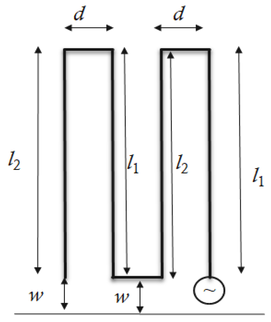
As the next step, we folded the antenna once. These models are called the single-folded (SF) antenna models. Once an antenna is folded, there are additional properties that need to be considered such as the feed wire length (), return wire length (), feed wire radius (), return wire radius (), wire separation (d), and the wire-to-ground separation (w). Figure 1 shows the parameters of the antenna model and Table 1 shows the parameters used in each model. In SF model 1, we kept the total wire length at 1 m, similar to the height of the monopole, but the antenna height was halved compared to the monopole. The other single-fold antenna models contain different parameter changes, as given in Table 1.
The goal of this study was to see whether we can achieve the same radiated power as the monopole antenna without changing the antenna height, but by changing another parameter. Having this in mind, we folded the antenna twice and created the two-fold (TF) antenna models. Folding the antennas multiple times introduces multiple parameters, but in this case, we changed only a limited number of parameters. Figure 2 shows the parameters used in the two-fold antenna and Table 2 shows the values used in each simulation.
To save simulation time, the 3D meshing was carried out in 5° increments in the and directions. We conducted a far-field radiation field analysis with a range of frequencies from 50 to 125 MHz. The frequency array was linearly spaced with 20 elements, which is the maximum number of frequency elements supported in the student’s version. The input power was set to 1 Watt, and it was fed to the antenna via a transmission line without impedance matching. The source impedance was 50 Ω.
3. Results
3.1. The Single-Fold Monopole
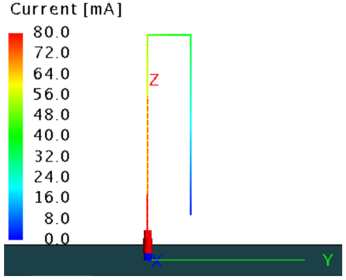
Figure 3 shows the far-field radiation pattern of single-fold antenna model 1. The radiation pattern is similar to that of a monopole, but the directive is slightly lower compared to a quarter-wave monopole. Figure 4 shows the segment currents of the single-fold monopole antenna (SF model 1). The maximum segment current close to the source is 80 mA.
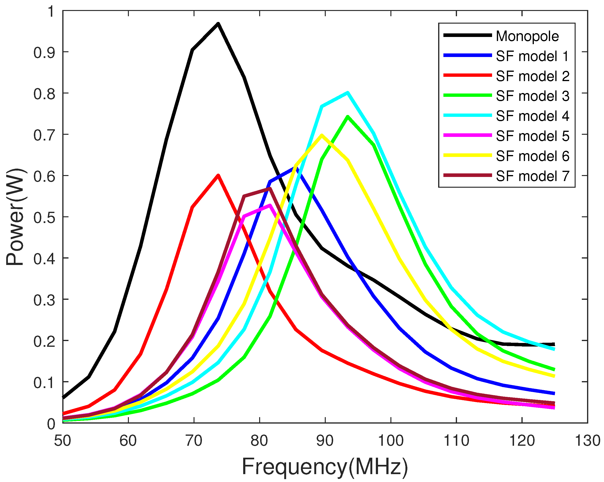
Figure 5 shows the radiated power vs. the operational frequency range of the antenna. Figure 6 shows the reflection coefficient of the monopole and each single-fold antenna model with respect to the frequency. The frequency at which the minimum reflection coefficient (maximum transmission coefficient) was observed is considered to be the resonance frequency of the antenna. Once the antenna is folded, the resonance height is not easily determined as in the case with a standard monopole or a dipole. In Figure 5, the curve in Black shows the radiated power of a standard quarter-wave monopole resonating at 75 MHz. The first single-fold monopole (SF model 1) was created by keeping the same total wire length as the monopole (1 m). The far-field radiated power for the SF model 1 is shown in Blue. With folding the antenna, the radiated power decreased to 0.6 W compared to almost 1 W of the monopole. At the same time, the resonance frequency of the antenna shifted to 85 MHz. It is worth noting here that the physical height of the antenna here is 0.5 m, which is half of the monopole. At 85 MHz, the quarter-wavelength is 88 cm. Therefore, it can be said that single-fold antenna model 1 (SF model 1) has an effective length of 88 cm instead of 50 cm ().
Single-fold antenna model 2 (SF model 2) has a separation (d) of 20 cm between the feed wire and the return wire. In this case, the resonance frequency of the antenna was at 75 MHz, similar to the resonance frequency of the monopole. The radiated power in this case, as shown in red, is similar to SF model 1. Decreasing the separation (d) between the feed wire and the return wire increases the radiated power in the far field, as shown in green for SF model 3, to 0.7 W. In this scenario, the resonance frequency of the antenna increased to 95 MHz, and the radiated power is higher than SF models 1 and 2. At 95 MHz, the quarter-wavelength is 79 cm. Therefore, in the case of SF model 3, the effective antenna length is 79 cm, which is higher than its physical height (50 cm).
Single-fold model 4 (SF model 4) shows the highest far-field radiated power of all single-fold antenna models. According to the cyan curve in Figure 5, SF model 4 radiates 0.8 W at 95 MHz. The only difference between this model and SF model 1 is that the return wire length () is shorter by 10 cm. According to the results, reducing or increasing the separation between the ground-to-wire separation (w) increases the power radiated in the far field. Here, again, the resonance length of the antenna is around 79 cm, which is higher than the physical height of the antenna. SF model 5, shown in magenta, was created by increasing the return wire length () by 5 cm or by decreasing the ground-to-wire separation (w) by 5 cm. According to the simulation results, this model shows the lowest far-field radiated power compared to all models. In conclusion, increasing w or decreasing increases the far-field radiated power. The last two models, SF models 6 and 7, show the far-field radiated power obtained by changing the feed wire radius () while keeping the return wire radius () fixed at 1.5 mm. In SF model 6, is twice the value and, in model 7, it is halved compared to the other. From the obtained results, increasing the feed wire radius compared to the return wire radius increases the far-field radiated power (in yellow) compared to the case where the two radii are the same, and decreasing it shows the opposite results (in brown). It is worth noting the shift in resonance frequency in the two cases, although there is no change to the total wire length.
Figure 7 shows the directivity of each model in 2D spherical coordinates. The coarseness of the plots is due to the high increments in and directions to save computational time. All plots were created at the resonance frequency (frequency with the highest radiated power) of each model and at = 0. All models have the same beam width. Single-fold model 4 (shown in cyan) and model 6 (in yellow) have zenith angles of 60°, whereas the other models and the monopole have zenith angles around 50°. SF models 2 and 4 show the highest directivities at the respective resonance frequencies. The gain of SF model 1 is significantly lower than the gains of other models and the standard quarter-wave monopole.
3.2. The Two-Fold Monopole
After observing the above results, we folded the monopole once again such that the height of the antenna became 25 cm. With multiple folds, we can vary multiple parameters. However, here, we kept the number of variables limited, as shown in Table 2. The variables are marked in Figure 2.
Figure 8 shows the radiation pattern of the two-fold model 1. This radiation pattern is similar to the radiation pattern observed for SF model 1 and for a quarter-wave monopole. Figure 9 shows the segment current along the antenna. The maximum current close to the source is 54 mA, which is lower than the maximum current observed for SF model 1 in Figure 4. This difference is due to impedance mismatch between the source and the antenna. It can also be said that the multi-fold antenna increases the impedance mismatch between the source and itself.
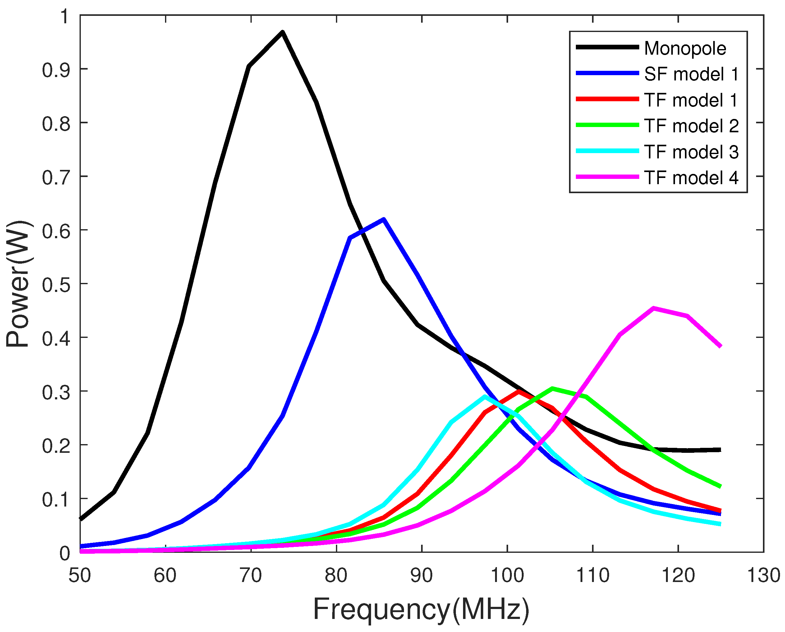
Figure 10 shows the far-field radiated power vs. the frequency of the monopole, single-fold (SF) model 1 and four two-fold (TF) models and Figure 11 shows the reflection coefficient corresponding to each model in Figure 10. The properties of the two-fold models are given in Table 2. All the TF models show a shift in resonance frequency. The monopoles were folded twice such that the physical height of the antenna is 25 cm (one-quarter of the quarter-wavelength monopole). The TF model 1 (in Red) shows resonates at 100 MHz. For the resonance frequency of 100 MHz, the quarter-wave monopole height should be 75 cm. Hence, the folded antenna shows the effective length of 75 cm. The antenna model TF model 2 (shown in green) was created by doubling the radius of the feed wire () and TF model 3 (shown in cyan) was created by halving it compared to the return wire radius . Changing the feed wire radius to the return wire radius does change the far-field radiation power. Between the three models, the resonance frequency changes, such that doubling the feed-wire radius increases the resonance frequency and halving it reduces the resonance frequency by about 5 MHz from TF model 1. Folding the antennas multiple times increases the resonance height of the antenna. In this case, the physical height of the antenna is 25 cm but the effective length of the antenna is around 75 cm. One disadvantage of folding the antenna is that the far-field radiation power reduces. From the results shown in Figure 10, the two-fold antenna models radiate half of the power as a single-fold monopole and one-quarter of the power is radiated by a monopole made with a similar wire length. However, this can be due to the impedance mismatch between the transmission line input and the antenna (load) and can be eliminated by having good impedance matching. It was shown from the results of the single-fold antennas that reducing the return-wire length () or increasing the wire-ground separation (w) increases the radiated power in the far field. In two-fold (TF) antenna model 4, shown in magenta in Figure 10, increasing w increases the far-field radiated power by about 0.2 W compared to the other two-fold models. It also increases the resonance frequency of the antenna.
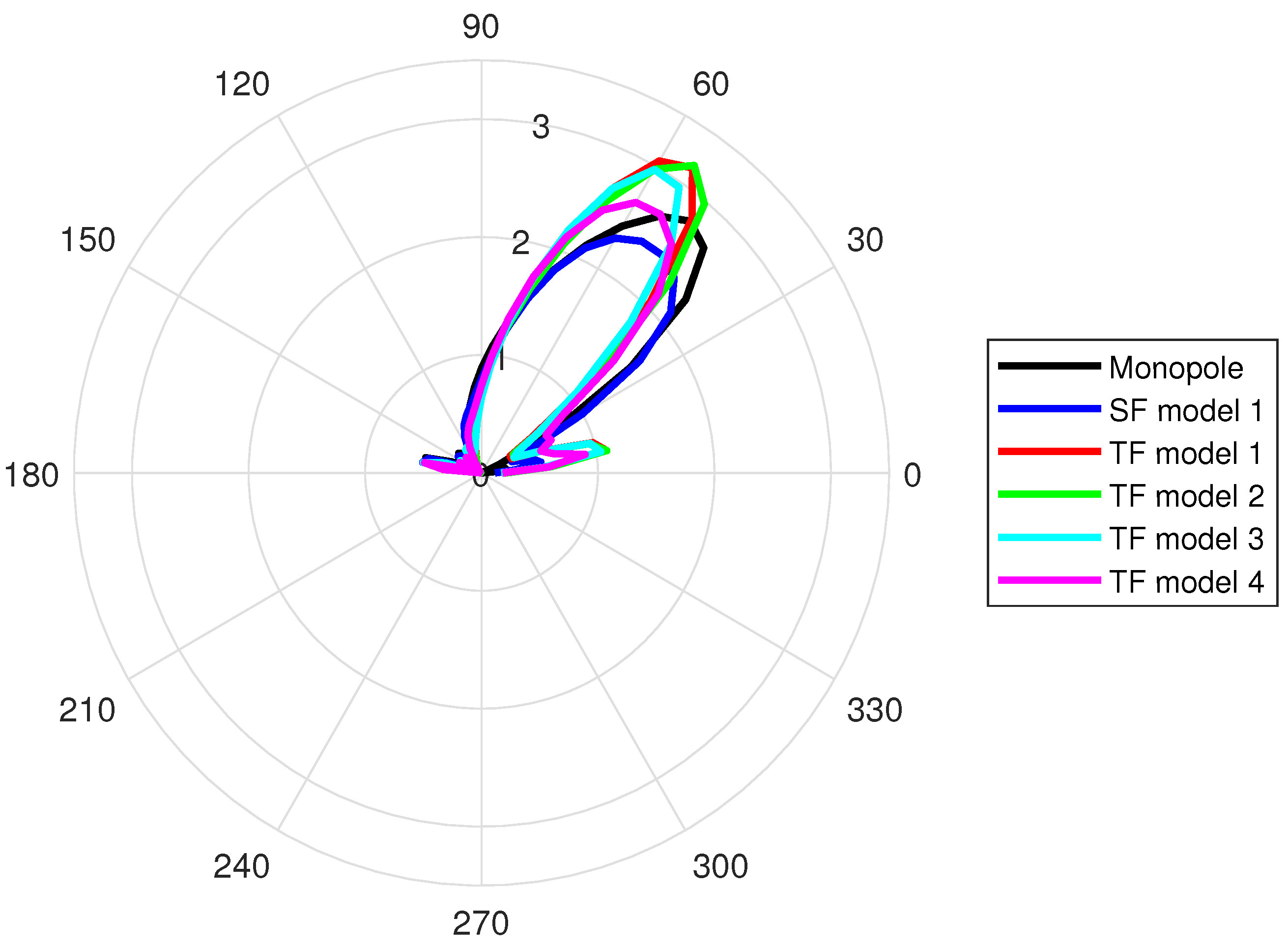
Figure 12 shows the directivity of the two-fold antenna models in comparison to the monopole and single-fold antenna model 1. From the results, it can be seen that all models have similar beam widths. However, except for TF model 4, the two-fold antenna models show more directivity compared to the monopole and SF model 1. For the two-fold antenna models, the feed-wire radius to return-wire radius does not show much of an impact as in the case for the single-fold antenna models. At the same time, similar to the single-fold antenna models, increasing the wire-to-ground separation (w) increases the far-field radiated power while showing a reasonable directivity.
4. Discussion
Based on our simulation results, the highest effect on the far-field radiated power is from the ground-to-wire separation. However, future work is need to quantitatively identify this value. In addition, with the change in every parameter, the frequency where the highest power is observed also changes. Therefore, it is important to derive mathematical expressions to quantify these design parameters concerning the radiated power. It is also important to quantify the effective length of the antenna at each resonance frequency. In this section, we expand our study using the existing formulas and propose modifications to fit the multiple fold scenarios.
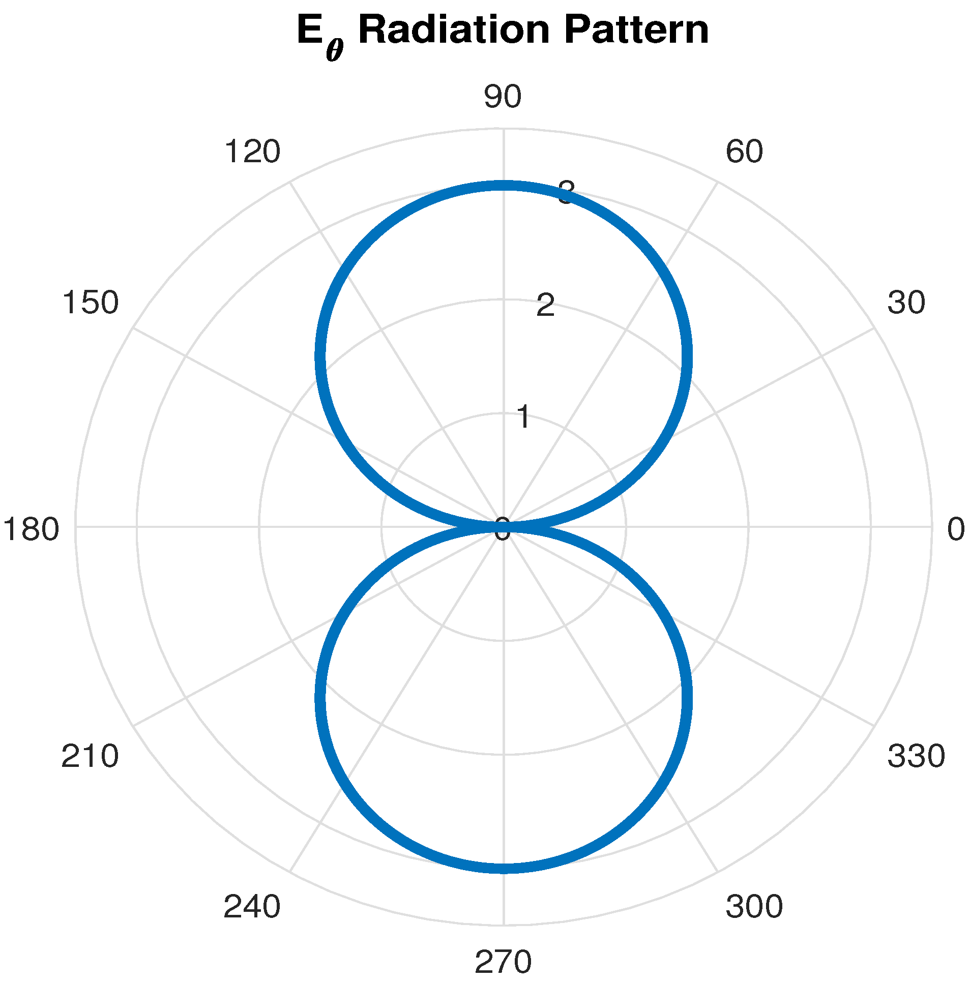
According to the previous literature, these folded monopole structures can operate in the common (or unbalanced or dipole) or the differential (balanced or transmission line) mode [12]. In a typical scenario it is a superposition of these two modes. The characteristic impedance is a term related to the transmission lines. Since the folded monopole antenas acts as a transmission line configuration the characteristic impedance is discussed here. In the common mode, both the feed wire and the return wire currents are in phase, but with different amplitudes. Figure 13 shows the radiation pattern of a folded monopole antenna generated by implementing the radiation pattern equations [12] on MATLABTM [20]. In this case, the goal was to identify the operational mode of the structures implemented in this article. The radiation pattern of a folded monopole without the ground plane was similar to the radiation pattern of a conventional dipole. Hence, the structures implemented in this work were operating in the common mode. In the differential mode, the feed wire current and the return wire current are 180° out of phase similar to a transmission line.
4.1. Characteristic and Input Impedance
From the results, it is clear that folding the antenna reduces the radiated power without impedance matching. Therefore, it is essential to identify the formulas for the input impedance of the folded antenna structures. The equations related to the impedance are listed below for common and differential modes are listed here [12].
The Equation (1), is indicates the common-mode characteristic impedance. The variables have the same meanings as used above, and where k is the wave number and is the quasi-static wave number. As seen from the Equation (1), the common mode characteristic impedance is independent from the ground-to- wire separation w, and dependent only on the wire separation d and the radii of the two conductors.
The Figure 14 shows the common mode characteristic impedance of single fold antenna models with respect to frequency. Given that the Equation (1) is independent of w, the SF models 4 and 5 will show similar characteristic impedance as SF model 1. According to the previous literature the common mode characteristic impedance can vary between 200–1200 Ω. Hence the values obtained here are well within that range.
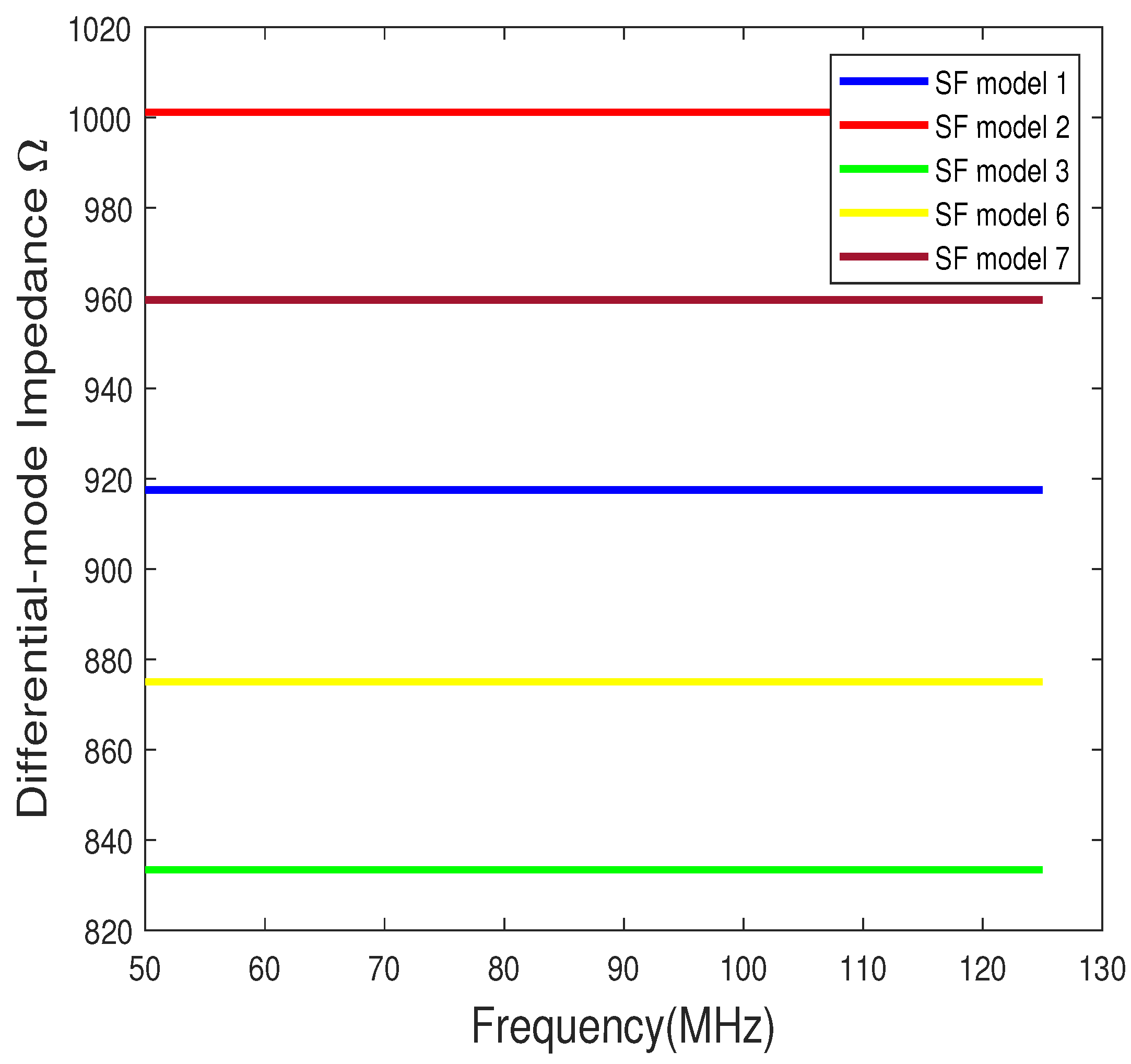
The Equation (2) indicates the differential mode characteristic impedance and Figure 15 shows the values with respect to the frequency. Since this calculation is independent of the wave number, there is no variation in impedance with respect to the frequency. Here again, the SF models 4 and 5 will have similar differential mode characteristic impedance to SF model 1. According to the previous literature the differential mode characteristic impedance is in the range of 20–200 Ω. But the values we have observed here are much higher than that. It might be due to the chosen design parameters given in Table 1.
Figure 16 and Figure 17 shows the common and differential mode characteristic impedance for the two-fold antenna models. In deriving the characteristic impedance for two fold antennas, in the common mode it is considered as two, single-fold antennas in series. In the differential mode, no series combination is considered, since in the differential mode the sources are balanced, hence each fold is treated as one transmission line. The design parameters for the two fold models are given in Table 2. But, the validity of these assumptions needs to be tested by lumped element circuit modeling and hardware testing.
4.2. Numerical and Simulated Input Impedance
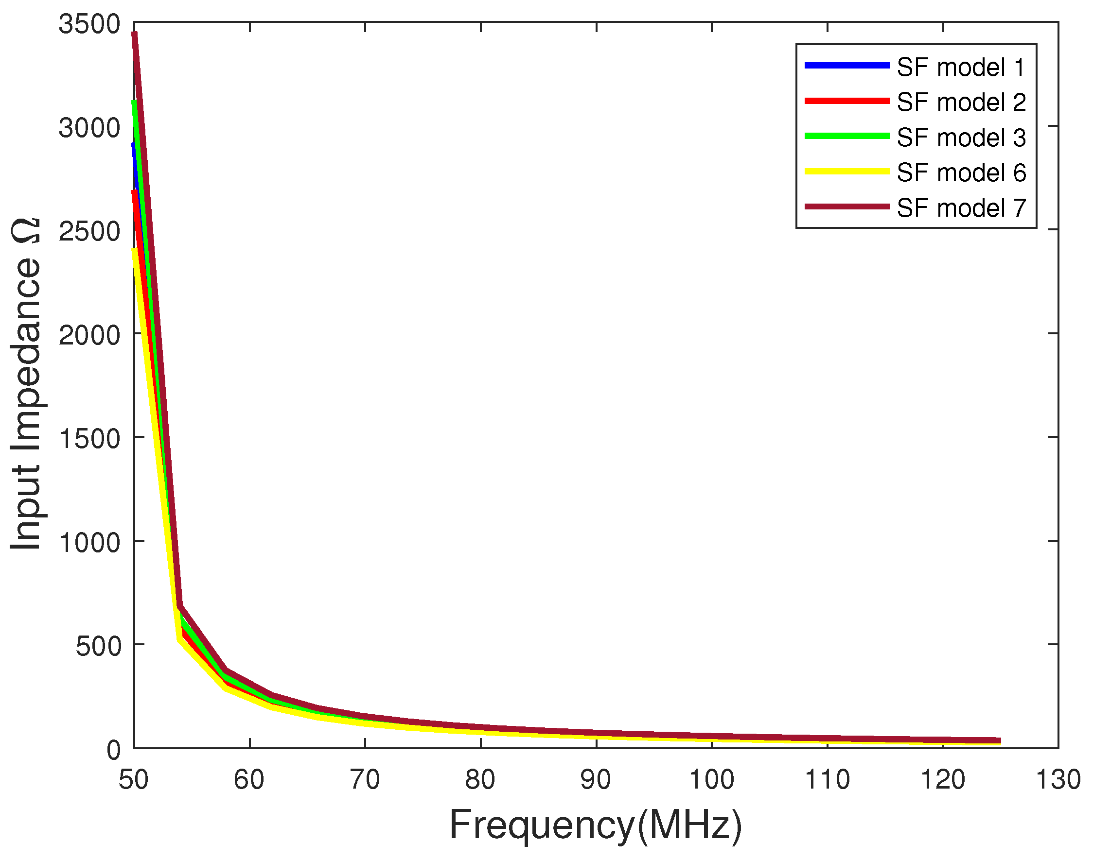
The Equation (3) shows the current transformation ratio between the feed wire and the return wire. The Equation (4) indicates the input impedance of the antenna. There and indicate the forward and reverse currents in the differential mode. Also, Γ is the reflection coefficient. The real part of Equation (4) is the input resistance and the imaginary part will be the input reactance. Figure 18 and Figure 19 show the input impedance for the single-fold and two-fold antennas calculated numerically. These impedance are calculated assuming that the forward and reverse currents and are zeros. In that case, since the input impedance depends only on the common mode characteristic impedance, the two-fold antenna input impedance is calculated assuming two single-fold antenna connected in series. The d, and radii parameters for SF and TF models are given in Table 1 and Table 2 respectively.
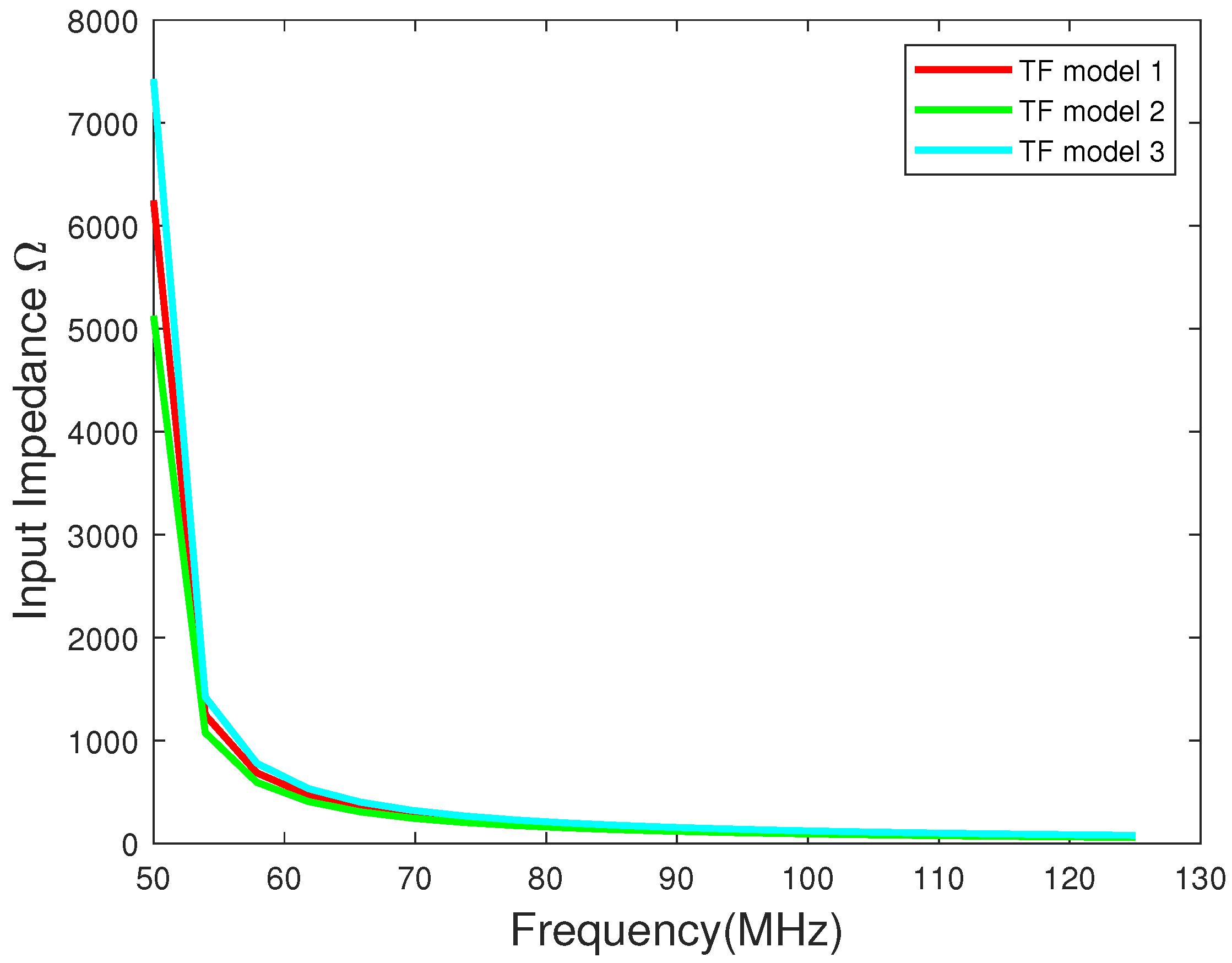
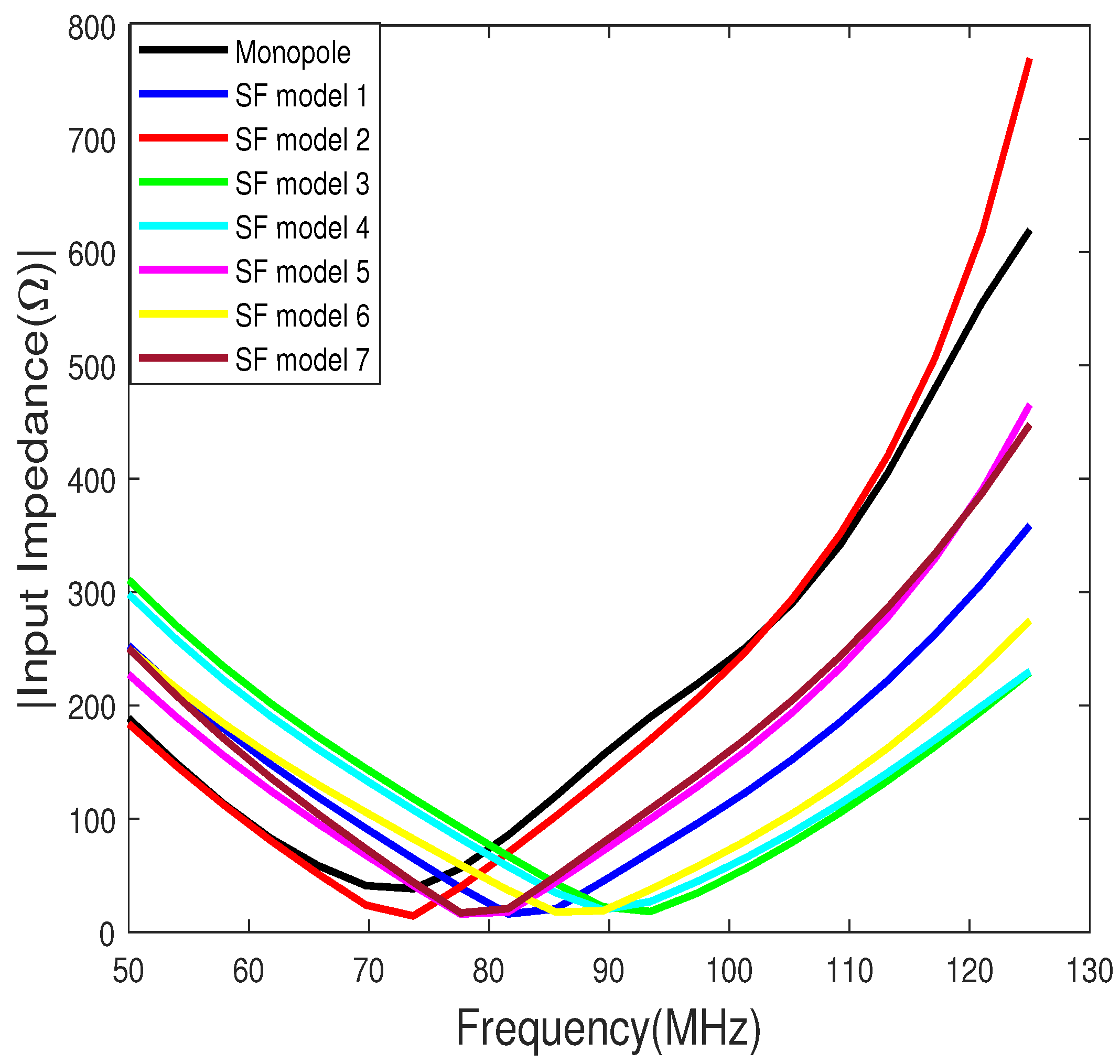
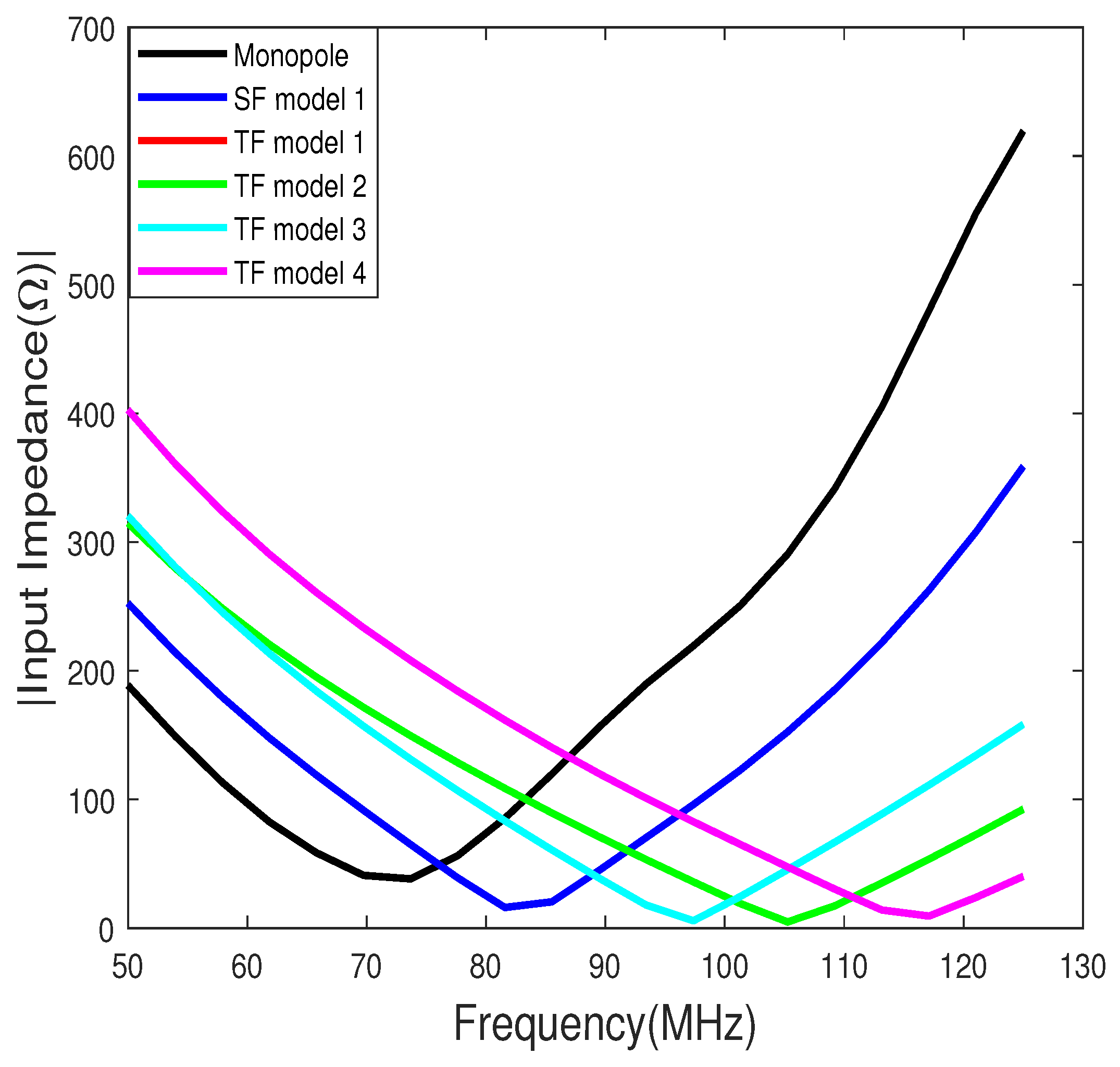
Figure 20, Figure 21, Figure 22, Figure 23, Figure 24 and Figure 25 show the input resistance, reactance, and the magnitude of the impedance for the single-fold and two-fold antenna models from the FEKO simulation software. It is important to note the difference between the numerical input impedance shown in Figure 18 and Figure 19, and the impedance received from FEKO shown in Figure 22 and Figure 25. The values from FEKO are much smaller compared to the values simulated numerically. Also, the shape of input impedance curves is different. Therefore, it is important to further study these discrepancies and incorporate those into the numerical equations. As mentioned above, impedance matching is essential when using folded antennas to reduce the reflected power. Therefore, it is important to perform future hardware testing to test the validity of the assumptions made in this work in deriving the two-fold antenna impedance.
5. Conclusions
Based on the above results we arrived at the following conclusions:
- Folded antennas are good candidates when antenna height is restricted, since folding the antenna increases the resonance length of the antenna without increasing the physical height of the antenna.
- Folding the antennas changes the resonance frequency of the antennas compared to a monopole. At the same time, folding the antennas introduces additional parameters and all those parameters affect the resonance frequency of the antenna differently. By adjusting these parameters, a folded antenna model can be designed to have the same resonance frequency as a monopole.
- With every fold, the far-field radiation power decreases. With every halving of the antenna height, and the radiation power also halves.
- For single-fold antenna models, the biggest effect on the far-field radiation power is attained by reducing the wire-to-wire separation (d) and by increasing the ground-to-wire separation (w). The highest far-field radiated power is obtained by increasing the ground-to-wire separation.
- The beam widths achieved from the single-fold monopoles and the traditional monopole are the same and there were no significant differences between the gains either.
- For the two-fold monopoles, the far-field radiation power can be increased by increasing the ground-to-wire separation similar to the single-fold monopoles.
- In both single-fold and two-fold cases, doubling the ground-to-wire separation increased the radiated power by 0.2 W compared to other single- and two-fold models.
- The two-fold antenna models show more directivity compared to the other models.
- There are significant differences between the calculated and simulated input impedance. Hence, appropriate measurements are needed to validate the models and equations.
From the results, it is clear that the folded monopole reduces the transmitted power unless there is impedance matching. Previous studies have shown numerical derivations for the input impedance and the radiation impedance. As for future work, we will be extending this study to derive the input impedance and the radiation impedance formulas for the multi-fold monopole antenna and deriving a lumped-element circuit model to represent these antenna structures. In addition to the simulations and mathematical expressions, it is necessary to perform a hardware analysis for the complete testing of the folded antennas.
Funding
This research received no external funding.
Institutional Review Board Statement
Not applicable.
Informed Consent Statement
Not applicable.
Data Availability Statement
Not applicable.
Conflicts of Interest
The author declare no conflict of interest.
References
- Balanis, C.A. Antenna Theory: Analysis and Design; Harper and Row: New York, NY, USA, 1982. [Google Scholar]
- Kraus, J.D.; Marhefka, R.J. Antennas for All Applications; McGraw-Hill: New York, NY, USA, 2002. [Google Scholar]
- Stutzman, W.L.; Thiele, G.A. Antenna Theory and Design, 3rd ed.; John Wiley and Sons: Hoboken, NJ, USA, 2012. [Google Scholar]
- Bell, T.F.; Inan, U.S.; Kimura, I.; Matsumoto, H.; Hashimoto, K. EXOS-B/Siple VLF wave-particle interaction experiments: 2. Transmitter signals and associated emission. J. Geophys. Res. 1983, 88, 295–309. [Google Scholar] [CrossRef]
- Helliwell, R.A. Siple station experiments on wave-particle interactions in the magnetosphere. In Wave Instabilities in Space Plasmas; Palmadesso, P.J., Papadopoulos, K., Eds.; Springer: Berlin, Germany, 1979; pp. 191–203. [Google Scholar]
- Helliwell, R.A. Controlled stimulation of VLF emissions from Siple Station, Antarctica. Radio Sci. 1983, 6, 801–814. [Google Scholar] [CrossRef]
- Helliwell, R.A. VLF wave-injection experiments from Siple Station, Antarctica. Adv. Space Res. 1988, 8, 279–289. [Google Scholar] [CrossRef] [Green Version]
- Maxworth, A.S. Multistation observations of the azimuth, polarization, and frequency dependence of ELF/VLF waves generated by electrojet modulation. Radio Sci. 2015, 50, 1008–1026. [Google Scholar] [CrossRef]
- Mielke, T.A.; Elkins, C.J.; Helliwell, R.A.; Inan, U.S. Excitation of whistler mode signals via injection of polarized VLF waves with the Siple transmitter. Radio Sci. 1992, 27, 31–46. [Google Scholar] [CrossRef]
- Barros, P.A. Design and Analysis of a Folded Meander Dipole Antenna Using the MININEC Program. Available online: https://digitalcommons.fiu.edu/cgi/viewcontent.cgi?article=2630context=etd (accessed on 29 November 2021).
- Raines, J.K. Folded Unipole Antennas Theory and Applications; McGraw-Hill: New York, NY, USA, 2007. [Google Scholar]
- Raines Engineering. Available online: https://www.rainesengineering.com/articles/SimpleFormulasFoldedAntennas.pdf (accessed on 29 November 2021).
- Esnagari, A.K.; Anantha, B. A Compact Microstrip-Line Fed Meandered Inverted-F MIMO Antenna. In Proceedings of the 2018 IEEE Indian Conference on Antennas and Propogation (InCAP), Hyderabad, India, 16–19 December 2018; pp. 1–4. [Google Scholar] [CrossRef]
- Hashmi, M.S.; Sharma, D. A meandered rectangular monopole antenna for quad-band applications. In Proceedings of the 2015 IEEE MTT-S International Microwave and RF Conference (IMaRC), Hyderabad, India, 10–12 December 2015; pp. 61–63. [Google Scholar] [CrossRef]
- Misman, D.; Aziz, M.Z.A.A.; Husain, M.N.; Soh, P.J. Design of planar meander line antenna. In Proceedings of the 2009 3rd European Conference on Antennas and Propagation, Berlin, Germany, 23–27 March 2009; pp. 2420–2424. [Google Scholar]
- Noordin, N.H.; Wong, Y.C.; Erdogan, A.T.; Flynn, B.; Arslan, T. Meandered inverted-F antenna for MIMO mobile devices. In Proceedings of the 2012 Loughborough Antennas and Propagation Conference (LAPC), Loughborough, UK, 12–13 November 2012; pp. 1–4. [Google Scholar] [CrossRef] [Green Version]
- Best, S.R. Improving the Performance Properties of a Dipole Element Closely Spaced to a PEC Ground Plane. IEEE Antennas Wirel. Propag. Lett. 2004, 3, 359–363. [Google Scholar] [CrossRef]
- Hung, T.; Hirayama, M.; Nagatoshi, M.; Morishita, H. Characteristics of U-shaped folded dipole antenna on a small ground plane. In Proceedings of the 2010 IEEE Antennas and Propagation Society International Symposium, Toronto, ON, Canada, 11–17 July 2010; pp. 1–4. [Google Scholar] [CrossRef]
- FEKO Software. Available online: https://www.altair.com/feko/ (accessed on 23 February 2022).
- MATLAB Software. Available online: https://www.mathworks.com/products/matlab.html (accessed on 3 March 2022).
Figure 1.
The parameters of the single-fold (SF) monopole.

Figure 2.
The parameters of the two-fold (TF) monopole.

Figure 3.
Far-field radiation pattern of SF model 1.

Figure 4.
Segment currents of SF model 1.

Figure 5.
Far-field radiated power vs. the frequency of operation.

Figure 6.
Reflection coefficient vs. the frequency of operation.

Figure 7.
Directivity of the antennas at the resonance frequency in spherical coordinates at .

Figure 8.
Far-field radiation pattern of TF model 1.

Figure 9.
Segment currents of TF model 1.

Figure 10.
Far-field radiated power vs. the frequency of operation.

Figure 11.
Reflection coefficient vs. the frequency of operation.

Figure 12.
Directivity of the antennas at the resonance frequency in spherical coordinates at .

Figure 13.
Far-field electric field pattern.

Figure 14.
Common mode characteristic impedance of single-fold (SF) antenna models with respect to frequency. SF models 4 and 5 will show similar characteristic impedance as SF model 1.
Figure 14.
Common mode characteristic impedance of single-fold (SF) antenna models with respect to frequency. SF models 4 and 5 will show similar characteristic impedance as SF model 1.

Figure 15.
Differential mode characteristic impedance of single-fold (SF) antenna models with respect to frequency. SF models 4 and 5 will show similar characteristic impedance as SF model 1.
Figure 15.
Differential mode characteristic impedance of single-fold (SF) antenna models with respect to frequency. SF models 4 and 5 will show similar characteristic impedance as SF model 1.

Figure 16.
Common mode characteristic impedance of two-fold (TF) antenna models with respect to frequency. TF models 4 will show similar characteristic impedance as TF model 1. Here we have modeled the two fold antenna as two single-fold antennas in series.
Figure 16.
Common mode characteristic impedance of two-fold (TF) antenna models with respect to frequency. TF models 4 will show similar characteristic impedance as TF model 1. Here we have modeled the two fold antenna as two single-fold antennas in series.

Figure 17.
Differential mode characteristic impedance of two-fold (TF) antenna models with respect to frequency. TF models 4 will show similar characteristic impedance as TF model 1.
Figure 17.
Differential mode characteristic impedance of two-fold (TF) antenna models with respect to frequency. TF models 4 will show similar characteristic impedance as TF model 1.

Figure 18.
Input impedance of single-fold (SF) antenna models with respect to frequency calculated from Equation (4). Numerically SF models 4 and 5 will show similar characteristic impedance as SF model 1.
Figure 18.
Input impedance of single-fold (SF) antenna models with respect to frequency calculated from Equation (4). Numerically SF models 4 and 5 will show similar characteristic impedance as SF model 1.

Figure 19.
Input impedance of two-fold (TF) antenna models with respect to frequency calculated numerically. TF models 4 will show similar characteristic impedance as TF model 1. Here we have modeled the two fold antenna as two single-fold antennas in series.
Figure 19.
Input impedance of two-fold (TF) antenna models with respect to frequency calculated numerically. TF models 4 will show similar characteristic impedance as TF model 1. Here we have modeled the two fold antenna as two single-fold antennas in series.

Figure 20.
Input resistance of the monopole and the single-fold antenna models from FEKO.

Figure 21.
Input reactance of the monopole and the single-fold antenna models from FEKO.

Figure 22.
The magnitude of the input impedance of the monopole and the single-fold antenna modals from FEKO.
Figure 22.
The magnitude of the input impedance of the monopole and the single-fold antenna modals from FEKO.

Figure 23.
Input resistance of the two-fold antenna models from FEKO.

Figure 24.
Input reactance of the two-fold antenna models from FEKO.

Figure 25.
The magnitude of the input impedance of the two-fold antenna models from FEKO.


Table 1.
Dimensions of the monopole and single-fold (SF) antennas.
| Model | (cm) | (cm) | d (cm) | w (cm) | (mm) | (mm) |
|---|---|---|---|---|---|---|
| Monopole | 100 | - | - | - | 1.5 | - |
| SF model 1 | 50 | 40 | 10 | 10 | 1.5 | 1.5 |
| SF model 2 | 50 | 40 | 20 | 10 | 1.5 | 1.5 |
| SF model 3 | 50 | 40 | 5 | 10 | 1.5 | 1.5 |
| SF model 4 | 50 | 30 | 10 | 20 | 1.5 | 1.5 |
| SF model 5 | 50 | 45 | 10 | 5 | 1.5 | 1.5 |
| SF model 6 | 50 | 40 | 10 | 10 | 3.0 | 1.5 |
| SF model 7 | 50 | 40 | 10 | 10 | 0.75 | 1.5 |
Table 2.
Dimensions of the two-fold (TF) antennas.
| Model | (cm) | (cm) | d (cm) | w (cm) | (mm) | (mm) |
|---|---|---|---|---|---|---|
| TF model 1 | 25 | 20 | 5 | 5 | 1.5 | 1.5 |
| TF model 2 | 25 | 20 | 5 | 5 | 3.0 | 1.5 |
| TF model 3 | 25 | 20 | 5 | 5 | 0.75 | 1.5 |
| TF model 4 | 25 | 15 | 5 | 10 | 1.5 | 1.5 |
Publisher’s Note: MDPI stays neutral with regard to jurisdictional claims in published maps and institutional affiliations. |
© 2022 by the author. Licensee MDPI, Basel, Switzerland. This article is an open access article distributed under the terms and conditions of the Creative Commons Attribution (CC BY) license (https://creativecommons.org/licenses/by/4.0/).
Share and Cite
MDPI and ACS Style
Maxworth, A. Far-Field Radiation Characteristics of Folded Monopole Antennas over a Conducting Ground Plane. Eng 2022, 3, 142-160. https://doi.org/10.3390/eng3010012
AMA Style
Maxworth A. Far-Field Radiation Characteristics of Folded Monopole Antennas over a Conducting Ground Plane. Eng. 2022; 3(1):142-160. https://doi.org/10.3390/eng3010012
Chicago/Turabian StyleMaxworth, Ashanthi. 2022. "Far-Field Radiation Characteristics of Folded Monopole Antennas over a Conducting Ground Plane" Eng 3, no. 1: 142-160. https://doi.org/10.3390/eng3010012