Article

Simplified Method for Calculating the Bearing Capacity of Slender Concrete-Filled Steel Tubular Columns

by
Anton Chepurnenko
1,*,
Vasilina Turina
1 and
Vladimir Akopyan
2
1
Structural Mechanics and Theory of Structures Department, Don State Technical University, 344003 Rostov-on-Don, Russia
2
Engineering Geology, Bases and Foundations Department, Don State Technical University, 344003 Rostov-on-Don, Russia
*
Author to whom correspondence should be addressed.
CivilEng 2023, 4(3), 1000-1015; https://doi.org/10.3390/civileng4030054
Submission received: 14 July 2023 / Revised: 15 August 2023 / Accepted: 22 August 2023 / Published: 7 September 2023
(This article belongs to the Section Construction and Material Engineering)

Abstract

:
Concrete-filled steel tubular (CFST) columns are one of the most effective reinforced concrete structures, and improving their calculation is a critical task. The purpose of this study was to develop a simplified method for calculating slender CFST columns, taking into account the effect of lateral compression. The idea of the method is to use the equation of a reinforced concrete column’s longitudinal bending, without taking into account the effect of lateral compression. To take into account the lateral effects, the cross-sectional stiffnesses are corrected based on the analysis of the stress–strain state in the cross-sectional plane using the finite element method. The developed method was implemented by the authors in the MATLAB environment. The approbation of the proposed method was carried out on experimental data for centrally compressed columns of a circular cross-section, as well as eccentrically compressed columns of a circular and square cross-section, presented in two papers. For the centrally compressed columns, we conducted a study on the influence of initial imperfections in the form of eccentricities and initial curvatures on the value of the ultimate load. For the eccentrically compressed columns of the circular and square cross-section, the area of their effective operation was determined.

1. Introduction

Currently, concrete-filled steel tubular columns are widely used in the construction of bridges, transport structures, and high-rise buildings [1,2,3,4]. An important feature of such structures, in comparison with traditional reinforced concrete elements, is their increase in bearing capacity due to the action of concrete in triaxial compression [5]. In addition, due to the clip effect, CFST columns are characterized by a plastic fracture pattern, even when high-strength concretes are used [6]. In addition to these factors, concrete-filled steel tubular columns have a number of significant advantages, including savings on formwork, the possibility of mounting the frame in the winter period, etc. [7].
Expanding the scope of CFST columns requires the development of methods for calculating their bearing capacity. Currently, a large amount of experimental research is being carried out on new types of pipe-concrete structures, including columns made of high-strength [8] and lightweight concrete [9]. Various types of cross-sections have been explored, including square and rectangular [10,11,12,13], hexagonal [14,15,16], octagonal [17], annular [18,19], elliptical, and oval [20,21] columns. In addition to the material of the core, the material of the shell also varies. For example, concrete-filled tubular columns with plastic [22] and fiberglass [23] shells are used.
Most of the existing methods for determining the bearing capacity of concrete-filled tubular columns are based on an empirical approach [10,11,12,16,17,20,21,24], which limits the applicability of these methods to a specific material of the concrete core and shell, as well as a certain cross-sectional shape, etc.
The most universal method for determining the bearing capacity of pipe-concrete columns is finite element modeling in a three-dimensional setting, taking into account the physical nonlinearity of the materials and the contact interaction between the concrete and shell [25]. In the case of slender columns, the stress–strain state of the elements will be affected by their deflections, increasing the bending moment. Therefore, when calculating such structures, it is also necessary to take into account geometric nonlinearity. However, this approach requires significant computing time for the calculation of a single element. It is not applicable in the calculation of buildings and structures, including a large number of pipe-concrete elements.
The authors of [26] present a technique for reducing the three-dimensional problem of calculating an eccentrically compressed short CFST column to a two-dimensional one based on the hypothesis of plane sections. A further development of this article [26] for the case of slender CFST columns is presented in [27], in which a combined finite element (FE) was proposed, connecting a classic bar FE with a transverse cut in the cross-section to take into account the effect of lateral compression. Compared to 3D modeling, this approach made it possible to reduce the number of unknowns by approximately four times without a significant loss in the accuracy of the results. However, this approach still cannot be considered sufficiently economical, since the system of FEM equations includes the displacements of all the calculated sections along the length of the element. The purpose of this study was to develop a more economical method in which the stress state in the plane of each section will be determined independent of the other sections.

2. Materials and Methods

Let us first obtain an equation for determining the deflections of a CFST element without taking into account the lateral compression stresses. When obtaining this equation, it is assumed that the eccentricity of the axial force exists only in the zOy plane (z is the longitudinal axis of the bar; the x and y axes are located in the cross-sectional plane). The elastic moduli of the concrete Eb and steel Es are taken as functions of the x, y, and z coordinates.
The increment in the total deformation of the concrete along the z axis is represented as the following sum:
Δ ε b z = Δ σ b z E b ( x , y , z ) + Δ ε b z * ,
where σ b z is the stress in the concrete according to z .
Here, Δ ε b z * is an additional term that allows one to take into account dilational deformations, temperature effects, the shrinkage and creep of concrete, etc.
On the other hand, the increment in the total deformation of concrete based on the hypothesis of plane sections can be written as the sum of the increment in axial deformation Δ ε z 0 and the increment in deformation caused by a change in curvature:
Δ ε b z = Δ ε z 0 + y Δ χ ,
where Δ χ = d 2 Δ v d z 2 is the element curvature increment, and v is the element deflection.
Based on (1) and (2), the increment in stress in the concrete along the z axis can be written in the form:
Δ σ b z = E b x , y , z Δ ε z 0 + y Δ χ Δ ε b z * .
Stress increments in a steel shell are determined based on the condition of compatibility of deformations along the z axis, as:
Δ σ s z = E s x , y , z Δ ε z 0 + y Δ χ .
The force increments in the column are the sum of the force increments undergone by the concrete and steel:
Δ N = Δ N s + Δ N b = A s Δ σ s z d A + A b Δ σ b z d A ,
Δ M = Δ M s + Δ M b = A s Δ σ s z y d A + A b Δ σ b z y d A ,
where A b and A s are the cross-sectional area of the concrete and steel parts, respectively.
Substituting (3) and (4) into (5) and (6), the following relationships between the increments in internal forces, Δ M and Δ N , and increments in generalized deformations, Δ ε z 0 and Δ χ , can be obtained:
Δ N Δ M = E A E S E S E I Δ ε z 0 Δ χ Δ N * Δ M * ,
where
E A ( z ) = A s E s x , y , z d A + A b E b x , y , z d A , E S ( z ) = A s E s x , y , z y d A + A b E b x , y , z y d A , E I ( z ) = A s E s x , y , z y 2 d A + A b E b x , y , z y 2 d A , Δ N * ( z ) = A b E b x , y , z Δ ε b z * d A ,   Δ M * = A b E b x , y , z y Δ ε b z * d A .  
According to (7), the increments in generalized deformations ε z 0 and χ are expressed in terms of internal forces increments, as follows:
Δ ε z 0 = E I E A · E I E S 2 Δ N + Δ N * E S E A · E I E S 2 Δ M + Δ M * ; Δ χ = E S E A · E I E S 2 Δ N + Δ N * + E A E A · E I E S 2 Δ M + Δ M * .
For the case of a column hinged at the ends (Figure 1), the increment in the bending moment will be written as [28]:
Δ M = F Δ v Δ F v + Δ F e 0 .
The term Δ F v in (10) represents the additional bending moment caused by the element deflection and takes into account the effect of column slenderness.
Substituting (10) into the second equation in (9) and taking into account that Δ χ = d 2 Δ v d z 2 and Δ N = Δ F , the following equation can be obtained:
E I E S 2 E A d 2 Δ v d z 2 + F Δ v = Δ F + Δ N * E S E A Δ F v + Δ F e 0 Δ M * .
For a column hinged at the ends, the boundary conditions have the following form:
Δ v 0 = Δ v L = 0 .
To obtain a resolving equation that is valid for other options for fixing, it is sufficient to differentiate Equation (11) twice with respect to z.
Let us further consider the effects of the lateral compression of concrete by a steel shell in Equation (11).
Equation (11) is solved using the finite difference method (FDM). To take into account the effects of lateral compression, the cross-sections are calculated using the finite element method for each node of the FDM mesh. The concrete part of the cross-section is meshed with triangular finite elements, and the steel shell is meshed with one-dimensional finite elements (Figure 2).
The load is increased stepwise in small portions. At the first load step, the modulus of elasticity of the concrete and steel are assumed to be constant, and the increment in the column deflection Δ v is determined in each section using Equation (11). Then, the element curvature increment Δ χ = d 2 Δ v d z 2 is calculated based on the value of Δ v , as well as the value Δ ε z 0 from the first equation in (9).
Based on the values of Δ χ and Δ ε z 0 , it is possible to determine the stress state change in the each cross-section plane from the solution of the FEM equations obtained in [26]:
K Δ U + Δ F b + Δ F s Δ F * = 0 ,
where Δ U is the vector of the displacement increments in the plane of the cross-section.
The stiffness matrix [K] is the sum of the stiffness matrices of the concrete part of the section K b and the steel part K s . For a single finite element, the matrices [ K b ] and [ K s ] appear as follows:
K b = B T D B A ; K s = E s h l ( 1 ν s 2 ) 1 1 1 1 ,
where B = 1 2 A b 1 0 b 2 0 b 3 0 0 c 1 0 c 2 0 c 3 c 1 b 1 c 2 b 2 c 3 b 3 is the matrix containing the gradients of triangular FE shape functions ( a 1 = x 2 y 3 x 3 y 2 , b 1 = y 2 y 3 , c 1 = x 3 x 2 , while the other coefficients a i , b i , c i are obtained using the cyclic substitution of indices), A is the cross-sectional area of the triangular FE, D = E 1 1 ν 1 2 1 ν 1 0 ν 1 1 0 0 0 1 ν 1 2 is the matrix of concrete elastic constants ( E 1 = E b 1 ν b 2 , ν 1 = ν b 1 ν b , ν b is the Poisson’s ratio of concrete), h is thickness of the steel shell, l is the length of a steel shell a one-dimensional FE, and ν s is the Poisson’s ratio of steel.
Vectors Δ F b ,   Δ F s ,   Δ F * , for a separate FE, are written as:
Δ F b = B T A E 1 ν 1 1 ν 1 2 Δ ε z 0 + y c Δ χ Δ ε b z * 1 1 0 ; Δ F s = B s T E s h ν s l 1 ν s 2 Δ ε z 0 + y s Δ χ ; Δ F * = B T D Δ ε * A ,
where y c = ( y 1 + y 2 + y 3 ) / 3 is the center of gravity coordinate for the triangular FE, y s is the center of gravity coordinate for the one-dimensional FE of the steel, and Δ ε * = Δ ε b x * Δ ε b y * Δ γ x y * is the vector of forced deformation increments, representing the sum of thermal deformations, creep deformations, shrinkage, and dilatational deformations in the cross-sectional plane.
The vector { F s } in (15), as well as the matrix [ K s ] in (14), are presented in the local coordinate system of the element (s axis in Figure 2). The transition from the local coordinate system to the global x O y system is performed using the following formulas:
U ¯ = L U ; K = L T K ¯ L ; F = L T F ¯ ; L = cos α sin α 0 0 0 0 cos α sin α .
where U ¯ ,   F ¯ ,   [ K ¯ ] are the nodal displacement vector, the nodal load vector, and the stiffness matrix in the local coordinate system; U ,   F ,   [ K ] are the same for the global coordinate system.
After determining the increments in displacements { Δ U } , the increments in stresses in the concrete are determined using the following formulas:
Δ σ b x Δ σ b y Δ τ b x y = D B Δ U b Δ ε * + Δ σ 1 , Δ σ b z = E b + 2 E 1 ν 1 1 ν 1 2 Δ ε z 0 + y c Δ χ Δ ε b z * + ν 1 1 0 D B Δ U b Δ ε * .
where Δ σ 1 = E 1 ν 1 1 ν 1 2 Δ ε z 0 + y Δ χ Δ ε b z * 1 1 0 , Δ U b = Δ u 1 Δ v 1 Δ u 2 Δ v 2 Δ u 3 Δ v 3 T is the displacement increment vector of the triangular concrete FE.
The increments in hoop stresses σ s θ and stresses along the z axis in the steel shell are calculated using the following formulas:
Δ σ s θ = E s 1 ν s 2 [ B s ] L { Δ U s } + ν s Δ ε z 0 + y s Δ χ ; Δ σ s z = E s 1 ν s 2 Δ ε z 0 + y s Δ χ + ν s B s L { Δ U s } ,
where B s = 1 l 1 l ;   Δ U s = Δ u 1 Δ v 1 Δ u 2 Δ v 2 T is the vector of displacement increments of a one-dimensional steel shell FE.
Based on the calculated stresses and strains, the tangential moduli of elasticity of the concrete and steel are corrected at each load step. The concrete tangential modulus of elasticity is determined in accordance with the concrete deformation theory of plasticity developed by G.A. Geniev [26] as a function of shear strain intensity Γ :
E b , t a n Г = E 0 1 Г Г s ,
where E 0 is the initial modulus of elasticity of the concrete; Γ = 2 3 ε 1 ε 2 2 + ε 2 ε 3 2 + ε 1 ε 3 2 ;   ε 1 , ε 2 , and ε 3 are the principal strains; and Г s is the ultimate intensity of shear deformations, which is determined using the following formula:
Γ s = Г c k λ , δ , k λ , δ = λ 1 + δ 2 + λ 2 1 + δ 2 4 + 1 + δ .
In Formula (20), Г c is the ultimate intensity of shear deformations in pure shear, and the parameters λ and δ are determined using the following formulas:
δ = e S T 3 ; λ = f σ T ,
where T = 1 6 σ 1 σ 2 2 + σ 2 σ 3 2 + σ 1 σ 3 2 is the shear stress intensity ( σ 1 , σ 2 , σ 3 are the principal stresses); e = R b R b t 3 T c 2 1 ; R b and R b t are, respectively, the strength of the concrete in compression and tension; T c is the ultimate intensity of shear stresses in pure shear; S = 3 1 2 σ 1 σ σ 2 σ σ 3 σ 1 3 ; and σ = ( σ 1 + σ 2 + σ 3 ) / 3 , f = 3 T c ( R b R b t ) R b R b t .
The value of T c was determined based on the strength criterion of P.P. Balandin [29], according to the following formula:
T c = R b R b t 3 .
The dilatation effect of concrete in the theory of G.A. Geniev is taken into account using an additional term called dilatational deformations ε d . The relationship between stresses and strains is represented in the following form:
ε b x = 1 E b Г σ b x ν b σ b y + σ b z + ε d ; ε b y = 1 E b Г σ b y ν b σ b x + σ b z + ε d ; ε b z = 1 E b Г σ b z ν b σ b x + σ b y + ε d .
When dilatation deformations occur in concrete, the steel shell tends to hold the concrete core, and concrete lateral compression occurs.
Dilatational deformations are determined using the following formula:
ε d = g 0 Г 2 / 3 ,
where g 0 = θ c / Г c 2 is the dilatation module, θ c = 1 · 10 4 is the ultimate volumetric deformation of concrete under pure shear, Г c = 2 T c / G 0 is the ultimate intensity of shear strains in pure shear, and G 0 = E 0 / ( 2 1 + ν b ) is the initial shear modulus of concrete.
When using Formulas (1), (3), (8), (15), and (17) in combination with the theory of G.A. Geniev, ε b x * = ε b y * = ε b z * = ε d , γ b x y * = 0 .
The steel of the shell is assumed as an ideal elastic-plastic material. The Huber–Mises–Genka plasticity criterion is used:
1 2 σ s z 2 σ s z σ s θ + σ s θ 2 = R y ,
where R y is the yield strength of steel.
When the steel shell reaches the plastic state at any point, the tangential modulus of elasticity of the steel at this point is reset to zero.
After adjusting the steel and concrete tangential moduli of elasticity, the stiffnesses of each section are recalculated according to the following formulas:
E A = h E s , i   l i + E b , i   A i , E S = h E s , i   l i y s , i   + E b , i   A i y c , i   , E I = h E s , i   l i y s , i   2 + E b , i   A i y c , i   2 .
Next, Equation (11) is solved at the next load step with corrected stiffnesses.
For the calculation, the authors developed a program in the MATLAB environment. The finite element mesh in the cross-section was generated using the PDE Toolbox package.

3. Results and Discussion

The approbation of the developed calculation method was carried out on experimental data for centrally compressed slender CFST columns presented in [30], as well as experimental data for eccentrically compressed slender CFST columns presented in [31].
The authors of [30] presented the results of short-term tests for the central compression of eight series of prototypes with different geometric and design parameters, having a slenderness λ ranging from 20 to 80. The cross-section of all the samples is a circle with a diameter of 108 mm. The steel shell was taken in the form of longitudinally electric-welded pipes with a wall thickness of 5 mm and a yield strength of 345 MPa. The compressive strength of the concrete used in the core of the CFST structures varied from 30.4 to 55 MPa.
Since only the prismatic compressive strength Rb was provided for concrete in [30], the rest of the model parameters (Rbt, E0) were calculated using the empirical formulas given in [32]:
E 0 = 1000 ·   0.04 R + 57 1 + 29 3.8 + 0.8 R ; R b t = 0.29 · R 0.6 ,
where R = R b / 0.788 is the cubic compressive strength of concrete.
The values in Formula (27) should be substituted in MPa.
Poisson’s ratio of concrete was taken equal to 0.2 in the calculations.
To calculate the centrally compressed columns, our technique requires one to specify the initial imperfections. Here, they were specified as a small random eccentricity e 0 or initial deflection v 0 x = f 0 sin π x L . The values of e 0 and f 0 were taken in the range from 1 to 5 mm. To take into account the initial curvature of the column in Equation (11), it suffices to replace e 0 with v 0 ( x ) .
Due to symmetry, half of the section was considered, and the finite element mesh generated in the MATLAB environment using the initmesh() function is shown in Figure 3. The average mesh size of the finite element mesh in this figure is 0.01 m.
The number of load steps was assumed to be 200. When solving Equation (11) using the finite difference method, the column was divided along its length into 20 segments. Neither refining the mesh in x , y , z nor increasing the number of steps in the load led to a significant change in the results. Figure 4 shows a graph of the ultimate load’s dependence on the size of the finite element mesh in the cross-section for the sample C.80.55 in Table 1, with an axial force eccentricity of 3 mm.
The characteristics of the experimental samples, the experimental values of the ultimate load N u ,   e x p , as well as its theoretical values N u , a n a l y s i s at various values of e 0 and f 0 are summarized in Table 1 and Table 2.
Table 1 and Table 2 show that initial imperfections in the form of random eccentricities and initial deflections significantly affect the ultimate load, especially for more slender columns, so that their maximum value must be controlled. The values of the ultimate loads, which differ from the experimental ones by no more than 5%, are presented in Table 1 and Table 2. Note that similar results regarding the effect of the initial imperfections on buckling beyond the elastic limit were obtained for wooden bars in [33].
It is also interesting to compare the calculation results with and without taking into account the lateral compression of concrete. Figure 5 shows deflection versus load plots for sample C80.35 with an axial force eccentricity of 5 mm. The dashed line corresponds to the solution without taking into account the lateral compression of concrete, and the solid line takes into account stresses in the cross-sectional plane. The ultimate load for the first and second cases were found to be 608 and 640 kN, respectively. Due to the effect of lateral compression, the increase in the bearing capacity was 5.3%.
With a decrease in the slenderness and the eccentricity of the axial force, the effect of lateral compression of concrete increases. For sample C20.55, with an eccentricity of axial force of 1 mm, the ultimate load without taking into account the lateral compression is 979 kN, and taking lateral compression into account, the ultimate load is 1127 kN, which is 13% higher. The corresponding deflection versus load plots are shown in Figure 6.
Let us proceed to a comparison with the results of the experiments on eccentric compression for slender CFST columns. In [31], circular and square cross-sectional columns with lengths of 3.3 and 6.6 m were tested at different axial force eccentricities. The concrete class was B60, according to the Russian standards ( R b = 43   MPa ,   R b t = 2.75   MPa ,   E 0 = 3.95 10 4   MPa), and the steel had the yield strength R y = 345 MPa. The wall thickness for all samples was taken as equal to 6 mm. For columns with a circular cross-section, the diameter d was 530 mm, and for the columns with a square cross-section, the side size a was 450 mm. With such cross-sectional dimensions, round and square columns are approximately the same in terms of material consumption. The authors of [31] also present results for centrally compressed columns. To calculate these, we set a random eccentricity equal to 1 mm.
For columns with both round and square sections, when calculating the stress state in the plane of the cross-section, we considered half of the cross-section (Figure 7).
Table 3 shows the characteristics of the specimens with a circular cross-section, the experimental and theoretical values of the ultimate loads, and the percentage deviation of the theory from the experiment Δ , calculated using the following formula:
Δ = | N u , e x p N u , a n a l y s i s | N u , e x p 100 % .
Table 4 shows the same for columns with a square cross-section.
The results given in Table 3 and Table 4 are graphically represented in Figure 8 and Figure 9 in the form of dependences of the ultimate load based on the ratio e 0 / d ( e 0 / a ).
Table 3 and Table 4 and Figure 8 and Figure 9 show good agreement between the experimental data and the calculated values. A deviation of more than 10% is observed only for two of the considered samples. The resulting deviation can be explained by the variety of material characteristics, as well as the presence of random eccentricities.
From Figure 8 and Figure 9, it can also be seen that for the CFST columns of a circular cross-section, the area of effective work is small eccentricities of the axial force, and with an increase in the eccentricity, it is more expedient to use columns of a square cross-section.
Note that the proposed approach makes it possible to calculate not only the columns but also any bar systems containing CFST elements. To do this, the bar finite elements with reduced stiffnesses EI, EA and ES should be used in combination with triangular and one-dimensional finite elements for the stress–strain state simulation in the plane of the cross-section. The stiffness matrix of the required bar finite element is given, for example, in [34].
It should also be noted that the proposed method is far more economical compared to the use of the combined finite elements proposed in [27], including a bar FE and a cross-sectional cut. In our method, the calculation of each cross-section is performed independent of the others, and the calculation process can be parallelized.

4. Conclusions

A simplified method for calculating slender CFST columns is proposed, which makes it possible to reduce the three-dimensional problem to a parallel calculation of the stress–strain state of individual cross-sections, in combination with the one-dimensional analysis of a bar. The proposed method was tested on experimental data for centrally compressed columns with a circular cross-section, as well as eccentrically compressed columns with circular and square cross-sections.
It was shown that initial imperfections in the form of random eccentricities of the axial force, as well as initial curvatures, can significantly affect the magnitude of the ultimate load.
For eccentrically compressed columns, good agreement between the experimental data and the calculation results was established. We theoretically confirmed that the area of effective operation of circular cross-section columns equates to small eccentricities of the axial force, and with an increase in eccentricity, columns with square cross-sections are more efficient with the same level of material consumption.
In the examples considered in our calculations, the nodes of the concrete and steel shell were taken to be identical, and the separation of the steel shell from the concrete was not taken into account. Our approach also allows one to take into account the separation of the steel shell from the concrete core. To do this, it is necessary to set one-sided connections between the nodes of the concrete and steel, which are absolutely rigid in the state of contact and have zero rigidity in its absence. Our further studies will be devoted to the analysis of the stress–strain state in this formulation.

Author Contributions

Conceptualization, A.C. and V.A.; methodology, A.C.; software, V.T.; validation, A.C. and V.A.; formal analysis, A.C.; investigation, A.C.; resources, V.A.; data curation, V.T.; writing—original draft preparation, A.C.; writing—review and editing, V.T.; visualization, A.C.; supervision, A.C.; project administration, A.C.; funding acquisition, A.C. All authors have read and agreed to the published version of the manuscript.

Funding

The APC was funded by Don State Technical University.

Data Availability Statement

This study does not report any data.

Acknowledgments

The authors would like to acknowledge the administration team of Don State Technical University for their resources and financial support.

Conflicts of Interest

The authors declare no conflict of interest. The funders had no role in the design of the study; in the collection, analyses, or interpretation of data; in the writing of the manuscript; or in the decision to publish the results.

Abbreviations

The following notations are used in this manuscript:
ε b x , ε b y , ε b z total deformations of concrete along the x, y, and z axes, respectively.
σ b x , σ b y , σ b z stresses in concrete according to x, y, z.
σ s z stress in steel according to z.
E b elastic modulus of concrete.
E s elastic modulus of steel.
ν b Poisson’s ratio of concrete.
ν s Poisson’s ratio of steel.
ε b x * , ε b y * , ε b z * components of the total deformation of concrete along the x, y and z axes, including the dilatational deformations, temperature effects, shrinkage and creep of concrete.
ε z 0 axial deformation.
χ curvature of the element.
F load.
N axial force.
M bending moment.
A b cross-sectional area of the concrete.
A s cross-sectional area of the steel.
E A cross-sectional stiffness in central tension (compression).
E I cross-sectional bending stiffness.
E S the product of the reduced modulus of elasticity and the static moment of the reduced section with respect to the geometric center of gravity.
e 0 
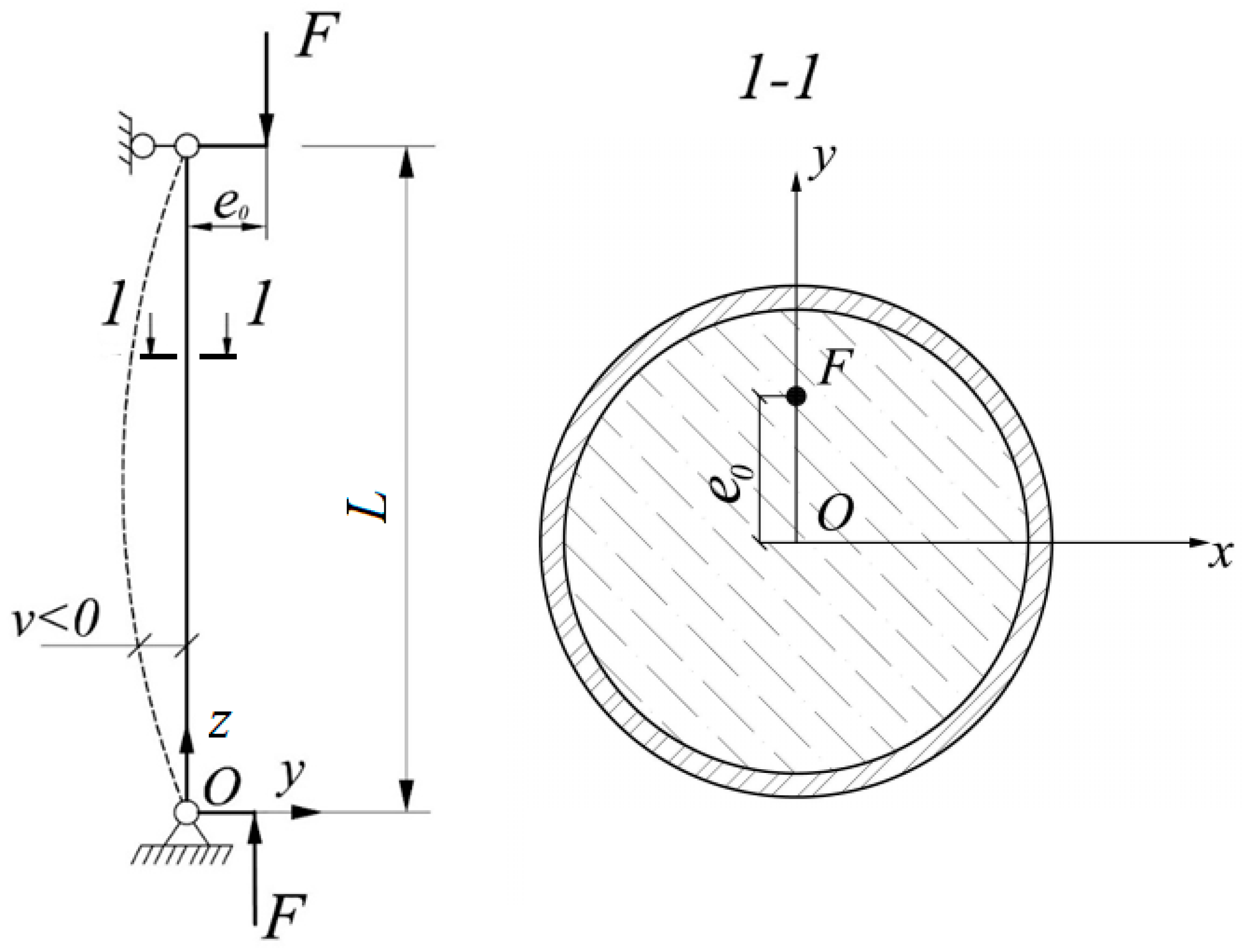
axial force eccentricity.
u displacement in the x direction.
v displacement in the y direction (deflection of the element).
L length of the column.
[ K ] stiffness matrix.
{ Δ U } vector of the displacement increments in the plane of the cross-section.
Fb}the vector of load increments in the plane of the cross-section on the concrete part.
Fs}the vector of load increments in the plane of the cross-section on the steel part.
{ Δ F * } vector of load increments due to creep, shrinkage, dilatation and temperature effects.
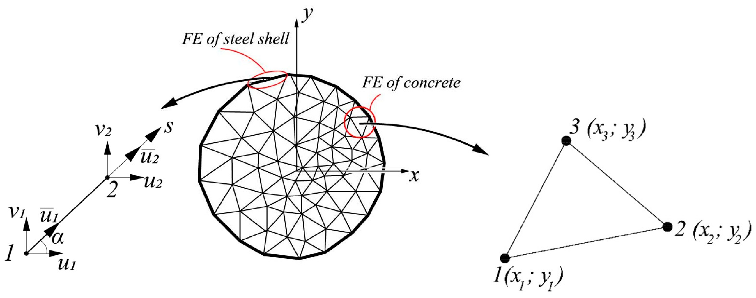
llength of the one-dimensional finite element of the steel shell.
[ B ] the matrix containing the gradients of triangular FE shape functions.
A cross-sectional area of the triangular FE.
[ D ] matrix of concrete elastic constants.
yccenter of gravity coordinate for the triangular FE.
yscenter of gravity coordinate for the one-dimensional FE of the steel.
[L]coordinate transformation matrix.
σsθhoop stresses in steel.
Гshear strain intensity.
E0initial modulus of elasticity of concrete.
ε1, ε2, ε3principal strains.
Гsultimate intensity of shear deformations.
k, λ, δ, e, f, Sparameters in the G.A. Geniev theory.
Tshear stress intensity.
σ1, σ2, σ3principal stresses.
Tcultimate intensity of shear stresses in pure shear.
σmean stress.
Rbcompressive strength of concrete.
Rbttensile strength of concrete.
εddilatational deformations.
g0dilatation module.
G0initial shear modulus of concrete.
Ryyield strength of steel.
Rcubic compressive strength of concrete.
ν0initial deflection.
f 0 maximum initial deflection.
Nu,expexperimental values of the ultimate load.
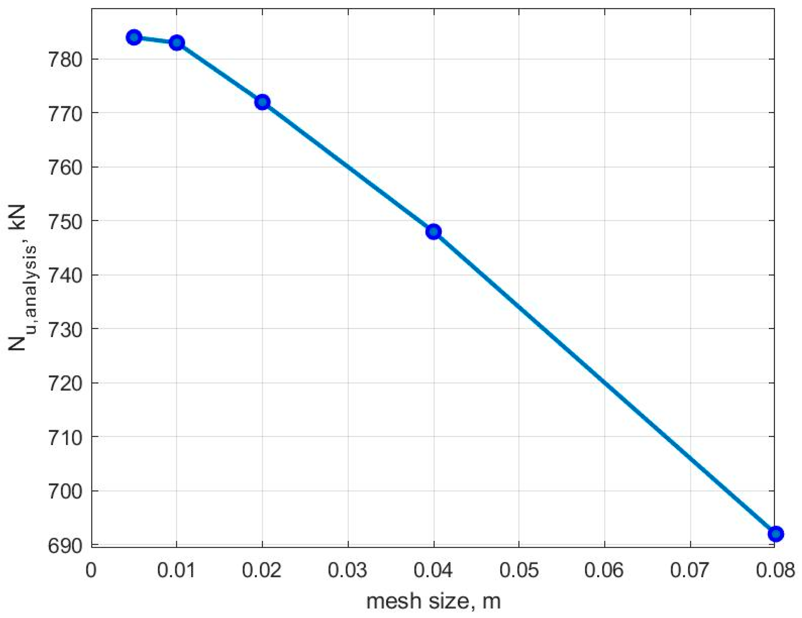
Nu, analysiscalculated values of the ultimate load.
Δ percentage deviation of the theory from the experiment.
ddiameter of circular cross-section.
hthickness of the steel shell.
adimension of square cross-section.

References

  1. Bai, Y.; Wang, J.; Liu, Y.; Lin, X. Thin-Walled CFST Columns for Enhancing Seismic Collapse Performance of High-Rise Steel Frames. Appl. Sci. 2017, 7, 53. [Google Scholar] [CrossRef]
  2. Zhou, X.; Liu, J. Application of Steel-tubed Concrete Structures in High-rise Buildings. Int. J. High-Rise Build. 2019, 8, 161–167. [Google Scholar] [CrossRef]
  3. Krishan, A.L.; Chernyshova, E.P.; Sabirov, R.R. Calculating the Strength of Concrete Filled Steel Tube Columns of Solid and Ring Cross-Section. Procedia Eng. 2016, 150, 1878–1884. [Google Scholar] [CrossRef]
  4. Krishan, A.L.; Astafeva, M.A.; Chernyshova, E.P. Strength Calculation of Short Concrete-filled Steel Tube Columns. Int. J. Concr. Struct. Mater. 2018, 12, 84. [Google Scholar] [CrossRef]
  5. Dong, H.; Li, Y.; Cao, W.; Qiao, Q.; Li, R. Uniaxial compression performance of rectangular CFST columns with different internal construction characteristics. Eng. Struct. 2018, 176, 763–775. [Google Scholar] [CrossRef]
  6. Narkevich, M.Y.; Sagadatov, A.I. Strength and deformation property enhancement of compressed steel tube-concrete elements using super concrete and thin-shell structure. IOP Conf. Ser. Mater. Sci. Eng. 2019, 687, 33031. [Google Scholar] [CrossRef]
  7. Romero, M.L.; Espinós, A.; Lapuebla-Ferri, A.; Albero, V.; Hospitaler, A. Recent developments and fire design provisions for CFST columns and slim-floor beams. J. Constr. Steel Res. 2020, 172, 106159. [Google Scholar] [CrossRef]
  8. Gao, H.; Zhang, L.; Xu, S.; Wang, Q.; Wen, S.; Wang, Y. Study on the mechanical property of low magnesia ore high strength concrete-filled steel tubular columns. J. Phys. Conf. Ser. 2021, 1904, 12021. [Google Scholar] [CrossRef]
  9. Natalli, J.F.; Andrade, H.D.; Carvalho, J.M.F.; Defáveri, K.; Castro Mendes, J.; Sarmanho, A.M.C.; Peixoto, R.A.F. Performance of lightweight concrete with expansive and air-entraining admixtures in CFST columns. J. Mater. Civ. Eng. 2020, 32, 4020121. [Google Scholar] [CrossRef]
  10. Chen, J.; Chan, T.-M.; Chung, K.-F. Design of square and rectangular CFST cross-sectional capacities in compression. J. Constr. Steel Res. 2021, 176, 106419. [Google Scholar] [CrossRef]
  11. Qu, X.; Chen, Z.; Sun, G. Axial behaviour of rectangular concrete-filled cold-formed steel tubular columns with different loading methods. Steel Compos. Struct. 2015, 18, 71–90. [Google Scholar] [CrossRef]
  12. Qu, X.; Chen, Z.; Sun, G. Experimental study of rectangular CFST columns subjected to eccentric loading. Thin-Walled Struct. 2013, 64, 83–93. [Google Scholar] [CrossRef]
  13. Hassanein, M.F.; Patel, V.I. Round-ended rectangular concrete-filled steel tubular short columns: FE investigation under axial compression. J. Constr. Steel Res. 2018, 140, 222–236. [Google Scholar] [CrossRef]
  14. Ma, D.Y.; Han, L.H.; Ji, X.; Yang, W.B. Behaviour of hexagonal concrete-encased CFST columns subjected to cyclic bending. J. Constr. Steel Res. 2018, 144, 283–294. [Google Scholar] [CrossRef]
  15. Xu, W.; Han, L.H.; Li, W. Performance of hexagonal CFST members under axial compression and bending. J. Constr. Steel Res. 2016, 123, 162–175. [Google Scholar] [CrossRef]
  16. Hassanein, M.F.; Patel, V.I.; Bock, M. Behaviour and design of hexagonal concrete-filled steel tubular short columns under axial compression. Eng. Struct. 2017, 153, 732–748. [Google Scholar] [CrossRef]
  17. Fang, H.; Chan, T.M.; Young, B. Structural performance of concrete-filled cold-formed high-strength steel octagonal tubular stub columns. Eng. Struct. 2021, 239, 112360. [Google Scholar] [CrossRef]
  18. Krishan, A.L.; Rimshin, V.I.; Troshkina, E.A. Strength of Short Concrete Filled Steel Tube columns of Annular Cross Section. IOP Conf. Ser. Mater. Sci. Eng. 2018, 463, 22062. [Google Scholar] [CrossRef]
  19. Krishan, A.; Astafeva, M. Strength and Deformability of the Concrete Core of Precompressed Concrete Filled Steel Tube Columns of Annular Cross-Section. MATEC Web Conf. 2019, 278, 3002. [Google Scholar] [CrossRef]
  20. Jamaluddin, N.; Lam, D.; Dai, X.H.; Ye, J. An experimental study on elliptical concrete filled columns under axial compression. J. Constr. Steel Res. 2013, 87, 6–16. [Google Scholar] [CrossRef]
  21. Uenaka, K. Experimental study on concrete filled elliptical/oval steel tubular stub columns under compression. Thin-Walled Struct. 2014, 78, 131–137. [Google Scholar] [CrossRef]
  22. Dolzhenko, A.V.; Naumov, A.E.; Klyuev, A.V.; Stoykovich, N. Experimental studies of the parameters of the contact problem in the design of plastic tube concrete structures. Mater. Sci. Forum 2020, 974, 542–550. [Google Scholar] [CrossRef]
  23. Krishan, A.L.; Narkevich, M.Y.; Sagadatov, A.I.; Rimshin, V.I. The strength of short compressed concrete elements in a fiberglass shell. Mag. Civ. Eng. 2020, 94, 3–10. [Google Scholar] [CrossRef]
  24. Mirza, S.A.; Lacroix, E.A. Comparative strength analyses of concrete-encased steel composite columns. J. Struct. Eng. ASCE 2004, 13012, 1941–1953. [Google Scholar] [CrossRef]
  25. Ouyang, Y.; Kwan, A.K.H. Finite element analysis of square concrete-filled steel tube (CFST) columns under axial compressive load. Eng. Struct. 2018, 156, 443–459. [Google Scholar] [CrossRef]
  26. Chepurnenko, A.; Yazyev, B.; Meskhi, B.; Beskopylny, A.; Khashkhozhev, K.; Chepurnenko, V. Simplified 2D Finite Element Model for Calculation of the Bearing Capacity of Eccentrically Compressed Concrete-Filled Steel Tubular Columns. Appl. Sci. 2021, 11, 11645. [Google Scholar] [CrossRef]
  27. Chepurnenko, V.S.; Khashkhozhev, K.N.; Yazyev, S.B.; Avakov, A.A. Improving the calculation of flexible CFST-columns taking into account stresses in the section planes. Constr. Mater. Prod. 2021, 4, 41–53. [Google Scholar] [CrossRef]
  28. Chepurnenko, A.; Lipovich, A.; Beskopylny, A.N.; Meskhi, B. Reinforced Concrete Columns with Local Prestressing Rebars: A Calculation Theory and an Experimental Study. Buildings 2022, 12, 1152. [Google Scholar] [CrossRef]
  29. Andreev, V.; Potekhin, I. Calculation of Equal Strength Thick-Walled Concrete Cylinder with Free Ends. IOP Conf. Ser. Mater. Sci. Eng. 2019, 661, 12023. [Google Scholar] [CrossRef]
  30. Krishan, A.L.; Surovtsov, M.M. Experimental Researches of Strength of Flexible Concrete-Filled Tube (CFT) Columns. Vestn. MGTU Named G.I. Nosov. 2013, 1, 90–92. Available online: https://cyberleninka.ru/article/n/eksperimentalnye-issledovaniya-prochnosti-gibkih-trubobetonnyh-kolonn (accessed on 14 July 2023).
  31. Krishan, A.L.; Troshkina, E.A.; Astafyeva, M.A. Strength of compressed concrete filled steel tube elements of circular and square cross-section. IOP Conf. Ser. Mater. Sci. Eng. 2018, 451, 12053. [Google Scholar] [CrossRef]
  32. Chepurnenko, A.; Nesvetaev, G.; Koryanova, Y.; Yazyev, B. Simplified model for determining the stress-strain state in massive monolithic foundation slabs during construction. Int. J. Comput. Civ. Struct. Eng. 2022, 18, 126–136. [Google Scholar] [CrossRef]
  33. Yazyev, S.B.; Chepurnenko, V.S.; Chepurnenko, A.S.; Sabitov, L.S. Calculation of the stability of compressed wooden rods under nonlinear creep. Struct. Mech. Calc. Struct. 2020, 4, 67–71. Available online: https://elibrary.ru/item.asp?id=43977092 (accessed on 14 July 2023).
  34. Yazyev, S.B.; Andreev, V.I.; Chepurnenko, A.S. Stability analysis of wooden arches with account for nonlinear creep. Adv. Eng. Res. 2021, 21, 114–122. [Google Scholar] [CrossRef]
Figure 1. Calculation scheme of a column with hinged supports at the ends.
Civileng 04 00054 g001
Figure 2. Representation of the CFST column cross-section in the form of a set of two-dimensional finite elements of concrete and one-dimensional finite elements of a steel shell.
Civileng 04 00054 g002
Figure 3. Finite element mesh in a cross-section for columns with a diameter of 108 mm.
Civileng 04 00054 g003
Figure 4. Dependence of the calculated ultimate load on the size of the finite element mesh in the cross-section for the sample C.80.55 ( e 0 = 3   mm).
Civileng 04 00054 g004
Figure 5. Deflection versus load graph for specimen C80.35.
Civileng 04 00054 g005
Figure 6. Deflection versus load graph for specimen C20.55.
Civileng 04 00054 g006
Figure 7. Finite element mesh for round and square cross-sections.
Civileng 04 00054 g007
Figure 8. Dependence of the ultimate load based on the ratio e 0 / d   ( e 0 / a ) for round (o) and square (□) columns at L = 3.3 m.
Civileng 04 00054 g008
Figure 9. Dependence of the ultimate load based on the ratio e 0 / d   ( e 0 / a ) for round (o) and square (□) columns at L = 6.6 m.
Civileng 04 00054 g009
Table 1. Comparison of experimental data for centrally compressed columns with the results of the calculation, specifying initial imperfections in the form of the eccentricity of the axial force.
SampleL, mmRb, MPa N u , e x p ,   k N N u , a n a l y s i s ,   k N at Various Eccentricities of the Axial Force
1 mm2 mm3 mm4 mm5 mm
C.20.3556033.61100920910880860840
C.20.5556055.011271116109210441032990
C.40.35112030.4760842815795769744
C.40.55112053.49071008966935910890
C.60.35164030.4735828783752720693
C.60.55164053.4797960910870840805
C.80.35220033.6714792736696664640
C.80.55220055.0762890828783743711
Table 2. Comparison of experimental data for centrally compressed columns with the results of the calculation, specifying initial imperfections in the form of initial deflection.
SampleL, mmRb, MPa N u , e x p ,   k N N u , a n a l y s i s ,   k N   at   Different   Values   of   Initial   Deflection   f 0
1 mm2 mm3 mm4 mm5 mm
C.20.3556033.61100935924902891880
C.20.5556055.011271116110410681014990
C.40.35112030.4760855828801779761
C.40.55112053.49071007979957940908
C.60.35164030.4735833792761734707
C.60.55164053.4797965925890855830
C.80.35220033.6714806761716684657
C.80.55220055.0762912851806770743
Table 3. Comparison of experimental data for eccentrically compressed columns of a circular cross-section with the calculation results.
e 0 / d N u , e x p , kN N u , a n a l y s i s , kN Δ , %
L = 3.3 m
015,21213,04014.2
0.12510,18292958.7
0.15939586458
0.2801576954
0.25708568603.2
0.375508651300.9
0.5379038702.1
L = 6.6 m
013,13312,9501.4
0.125844081004
0.15774275202.9
0.2671166151.4
0.25582258500.5
0.375418643654.3
0.5341133840.8
Table 4. Comparison of experimental data for eccentrically compressed columns of a square cross-section with the calculation results.
e 0 / a N u , e x p , kN N u , a n a l y s i s , kN Δ , %
L = 3.3 m
013,37612,3207.9
0.125941495501.4
0.15889491002.3
0.2782881604.2
0.25704873504.3
0.375535758208.6
0.54186475213.5
L = 6.6 m
011,96012,2852.7
0.125826184602.4
0.15768980004
0.2669372007
0.25593864358.4
0.3754504499811
0.5395240081.4
Disclaimer/Publisher’s Note: The statements, opinions and data contained in all publications are solely those of the individual author(s) and contributor(s) and not of MDPI and/or the editor(s). MDPI and/or the editor(s) disclaim responsibility for any injury to people or property resulting from any ideas, methods, instructions or products referred to in the content.

