Article

Failure Behavior of Composite Bolted Joints: Review

1
Civil Engineering, Southern Illinois University Edwardsville, Edwardsville, IL 62026, USA
2
Engineering Construction Department, Faculty of Engineering, Egyptian Russian University, Cairo 11829, Egypt
3
Civil Engineering Department, Jouf University, Sakaka, Jouf 72388, Saudi Arabia
4
Civil and Environmental Engineering Department, University of Missouri-Columbia, Columbia, MO 65211, USA
*
Author to whom correspondence should be addressed.
CivilEng 2022, 3(4), 1061-1076; https://doi.org/10.3390/civileng3040060
Submission received: 16 October 2022 / Revised: 27 November 2022 / Accepted: 28 November 2022 / Published: 5 December 2022
(This article belongs to the Special Issue Advances in Civil Engineering)

Abstract

:
The fiber-reinforced polymeric (FRP) composite can be joined by adhesive bonding or mechanically fastening the composite element. Carbon fiber-reinforced polymers (CFRP) and glass fiber-reinforced polymers (GFRP) are the most common types of polymers. Mechanically fastened or bolted joints do not need treatments, and the surface temperature and other environmental effects such as humidity do not affect its strength. In this research, the previous research that describes the behavior of the composite bolted joint (CBJ) is presented and summarized including the modes of failure of the CBJ, and the experimental works that explain the bearing failure (BF) of the CBJ. In addition, the effects of bolt clamping force (BCF) and techniques that are used to simulate the progressive failure and damage in composite materials and finite element simulation works are surveyed.

1. Introduction

Bolted joints (BJs) have several favorable benefits such as the easy mantling and dismantling processes. However, BJs can be addressed as the most critical location in the structural element design. High values of stress concentration are produced due to the existence of bolt holes [1,2]. In addition, much computational effort is needed for the fiber-reinforced polymeric material (FRP) BJs analysis and design owing to the orthotropic, inhomogeneous, and visco-elastic properties. Composite lay-up, joint geometry, the orientation of fiber, and bolt clamping force (BCF) are important factors that have to be considered for the design accuracy of the composite bolted joint (CBJ) [3,4]. The bolted composite plate geometric parameters are represented in Figure 1.
Predicting the strength and the modes of failure in a composite fastened joint is a challenge. Several earlier investigations identified the modes of failure and the parameters associated with them that are used for the characterization of composite bolted plate failure [5]. Figure 2 shows the most important modes of failure of the CBJ. Reduced connection width leads to a tensile failure mode, which concentrates stress in the layers of the composite plate. The reduction in the edge distance might lead to the shear-out failure mode. It can result mainly from the effect of compression or shear failure of the bolted composite plate. In most cases, increasing the edge distance and determining the suitable lay-up could help avoid this type of failure. Cleavage failure occurs when insufficient joint width is combined with insufficient edge distance [4].
A small ratio of thickness-to-bolt shank diameter could cause fasteners to fail [4]. Moreover, small bolt diameters can lead to fastener failure, though this is not a common mode of failure in composite joints. The combination of a large compressive force applied by the bolt shank on the internal boundary of the bolt-hole and a small diameter-to-width ratio can result in bearing failure (BF).
Net-tension and shear-out failure modes are the most catastrophic, while BF is the most progressive failure mode. Additionally, the loss of the composite connection’s capacity to carry loads may not be significant [6]. It is favorable for the design of bolted composite structures to be designed for the BF [4,7]; thus, demonstrating the effects of joint parameters on the joint BF is vital.
FRP composites are utilized as a part of a pinned/bolted joint setup and display a complex behavior under the effect of in-plane stresses, Figure 3. The bolt shank produces compression on the hole surface under the effect of in-plane loading which distorts the composite material and may prompt BF. ASTM D5961/D 5961M has details about the standard bearing test methodology [8]. Load vs. displacement data are monitored during the joint bearing test to find the bearing failure load, the ultimate strength, and the bearing strength of the bolts. Mechanical fasteners such as rivets and bolts need to make holes through the thickness of the composite plates, which breaks the reinforcement fibers. This makes stress concentration and might make local damage such as micro-scale cracks around the bolt hole inciting instability of structural elements [9]. Indeed, mechanical bolting of composites is a demonstrated practical technology, even with some of these downsides. The design variables and the factors influencing the behavior of CBJs were addressed [10]. The BF of FRP composites depends on the composite material properties such as matrix, fiber, and laminate properties. More experimental and numerical work is needed for a dependable joint design, as it is challenging to develop generalized design procedures and equations.
There is a significant need to study the bearing failure behavior of the CBJ as bolted joints represent the most critical location in the structural element. Bearing failure of CBJs, the stiffness, and the strength of the joint depends on the joint parameters. Joint geometry, clearance, fastener type, BCF laminate characteristics, and loading conditions are considered critical parameters. In this paper, the previous works that explain the bearing behavior of CBJs are summarized.

2. Effect of Joint Geometry and Laminate Properties

Different experimental and numerical works studied the influence of joint/connection properties, such as the joint geometry, the laminate material, and the laminate lay-up on the failure mechanisms, especially the bearing mechanism [11,12,13,14,15,16,17,18,19,20,21,22]. In this section, these papers are discussed in detail.

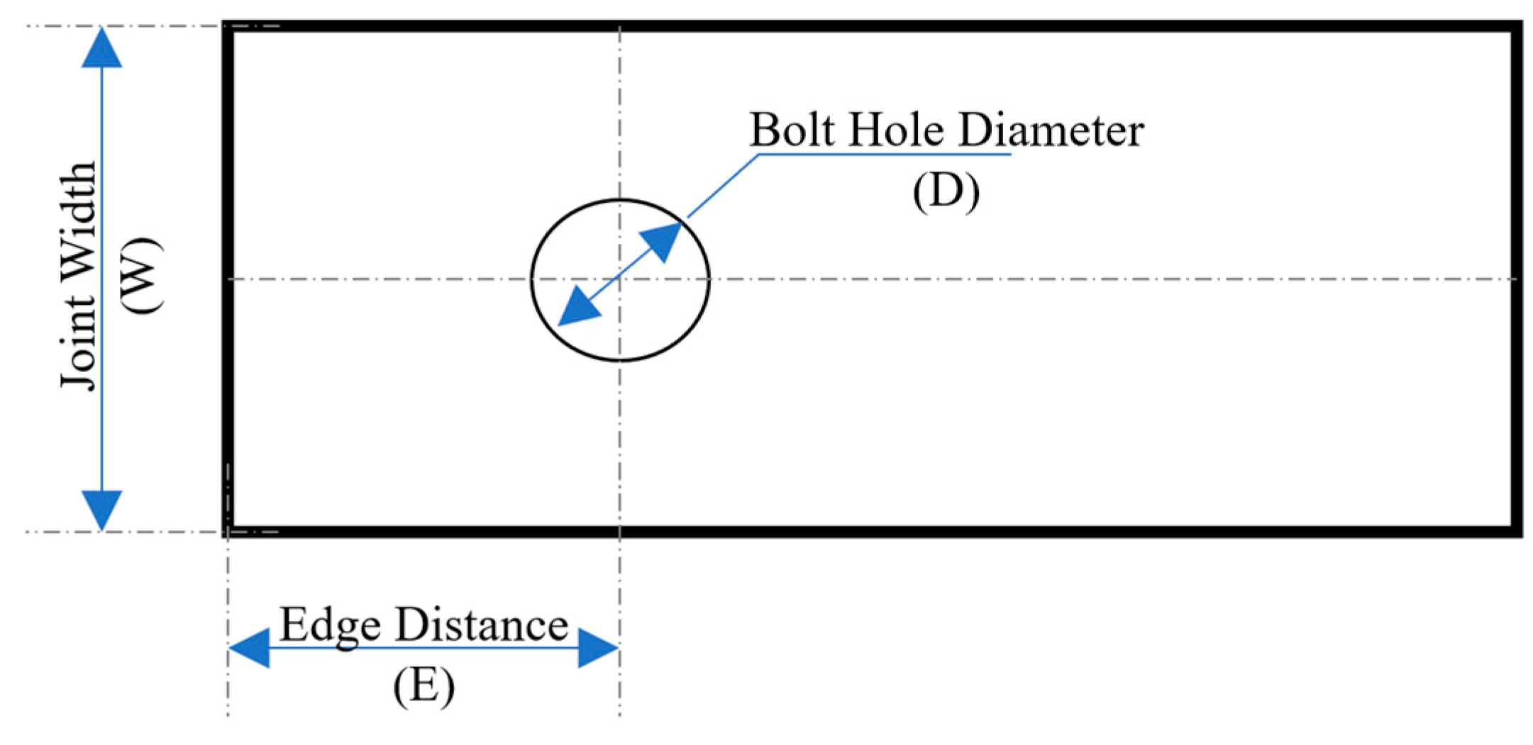
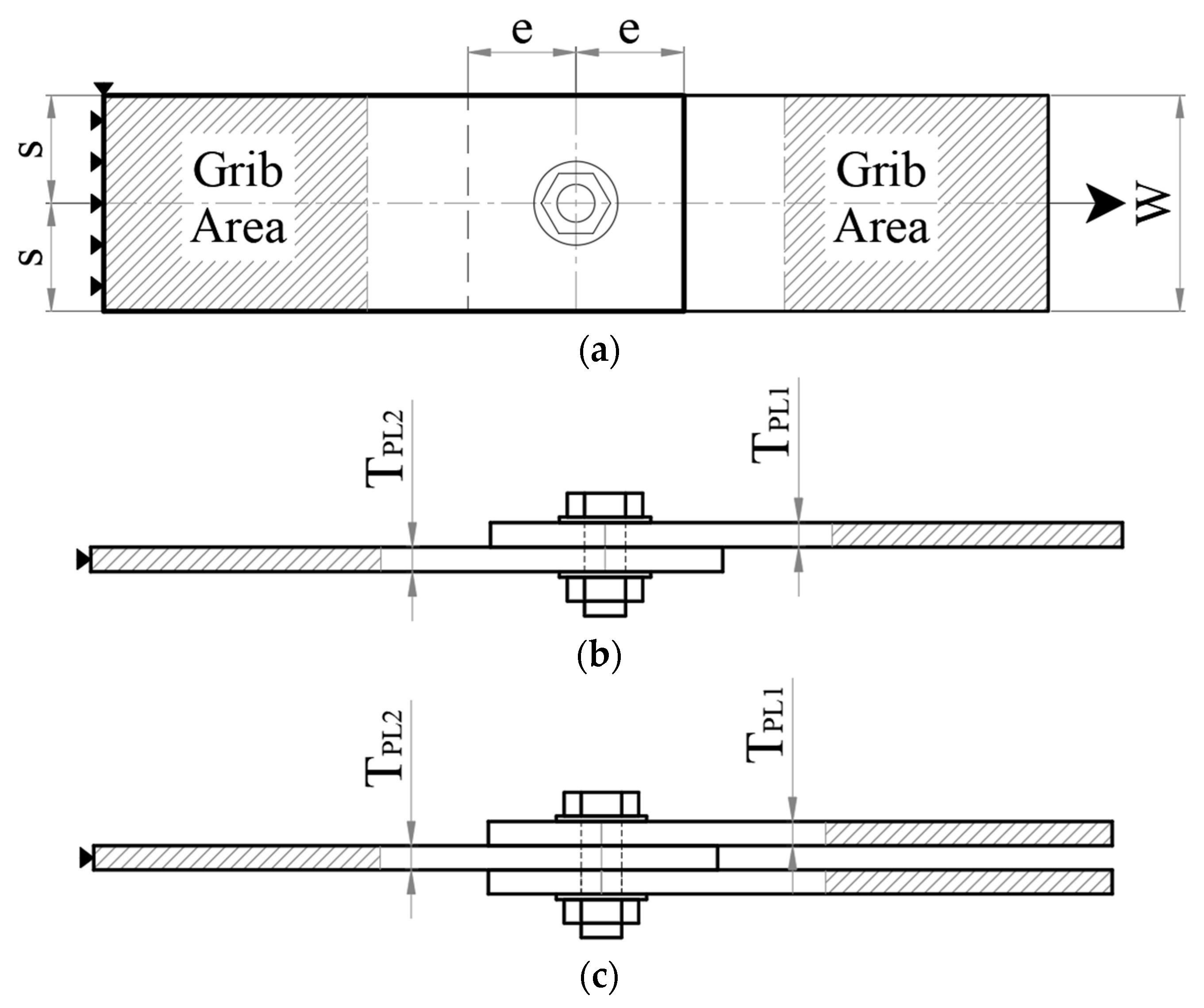
2.1. Effect of Side, Edge Distance, and Lateral Constrain

Figure 4 shows the basic geometric characteristics of single and double-lapped joints as seen in Figure 4b. Generally, the single-lapped joint consists of two plates and the double-lapped joint consists of three plates as seen in Figure 4b,c. Parameters such as the edge distance (e), width (W), side distance (S), and plate thicknesses (TPL1 and TPL2) control the behavior and failure mode of the joints.
Vangrimde and Boukhili [11] experimentally investigated the effect of joint geometry and composite material properties on the stiffness of joints made from glass fiber reinforced polymer (GFRP) plates. The load-displacement behavior was focused on the GFRP laminate. Both single and double-lapped joints were studied using laminated plates with different lay-ups. Different joint geometries were studied containing standard, long, and small coupons with different width-to-diameter ratios (WDR) ranging from 2 to 5. It was found that these stress–strain curves could mainly be divided into three different zones: the initial sliding zone, the linear bearing zone before the damage initiation, and a nonlinear zone after damage. The bolt-bearing stiffness was identified as the initial slope of the load-displacement relation. Small-width joints showed more yield behavior than the joints with standard dimensions with an insignificant effect of the end distance on the stiffness. The smaller coupon geometry gave higher bearing stiffness in the case of more fiber percent in the axial direction.
Belardi et al. [12] studied the multi-bolt composite joints by using the finite element (FE) modeling approach. Results showed that the distribution of bolt loads and secondary bending of the joint can be accurately determined using a simplified FE model with shell elements to represent the plates and the composite bolted joint element for the bolted region.
Li et al. [23] designed, fabricated, and conducted tensile tests on 16 sets of sandwich composite bolted joints with various end-distance-to-bolt-diameter and width distance-to-bolt-diameter ratios. To get the best load-carrying capacity, it is discovered that the design parameters must fulfill e/D of 3 and W/D of 5. This was able to prevent other types of failure modes such as net-tension, shear-out, and cleavage.
Cooper and Turvey [7] conducted experimental tests to study the effect of edge distance to hole diameter ratio e/D and width to hole diameter ratio W/D, the bolt tightening torque on the joint strength, bearing stiffness, and mode of failure of the single bolt lapped joint. The CBJ single bolt initial stiffness was impacted by the W/D ratio and the e/D ratios. The load–displacement response showed a small initial movement or displacement despite the case of tight fitting of the bolt. After this initial movement, the load-displacement graph was almost linear until the CBJ either failed (due to small edge or width ratios) or the stiffness degraded. After the joint stiffness is reduced, the bearing damage becomes irreversible; the damage load can be considered the onset of this zone.
Hou and Liu [24] studied the three-dimensional thickness and size constraints’ influences on the double and single-lapped pin joints. The thickness direction constraints, the thickness of the plate, the interlaminate bond strength, and the BCF have a remarkable influence on the strength and stiffness of the CBJ. The experimental results showed that by increasing the CBJ size, the strength decreases. The initial failure mode was bearing damage, which was ended by net section failure. For the cases with large joint sizes, direct catastrophic net-section failure was observed. For joints without thickness constraints, delamination and fiber buckling failure modes were evaluated, this makes the BF always happen before the net-tension failure. In these joints, the displacement at the final failure was very large, and the energy consumed by the joint was large compared with the samples that failed due to direct net-section sudden failure.
Based on the previous references it can be concluded that increasing the joint width, and edge distance and selecting the suitable lay-up could help to avoid several catastrophic failure modes such as net tension, cleavage, and shear-out failure modes. The smaller coupon geometry gave higher bearing stiffness in the case of more fiber percent axial reinforcement. In addition, when the edge and the width ratios are less than 4, the BF was the primary failure mode. When these ratios were less than 4, a mixture of net tension and shear-out failures was found.

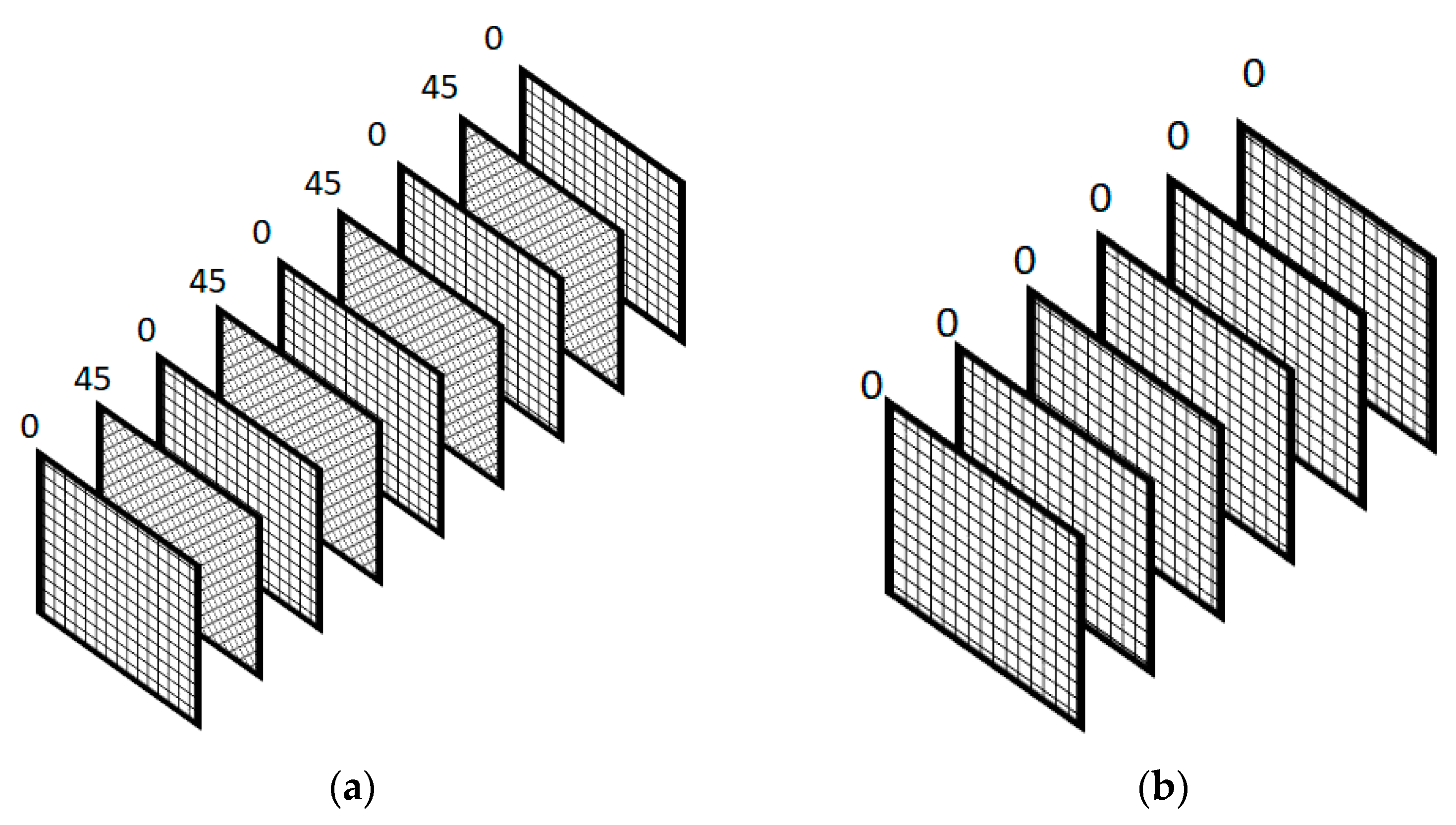
2.2. Effect of Lay-Up and Laminate Type

Commonly, FRP elements consist of two materials i.e., the matrix and the fiber. Matrix materials can be metals, ceramics, or polymers. The most common is the polymer matrices such as epoxy, due to their ease of fabrication of very complex parts with low manufacturing costs [25]. Several fibrous material types are found in the market. The most common nonmetallic fiber materials are carbon and glass fibers. The fibers can come if one-, two-, or three-dimensional textiles. In one dimension textile, the fabric has only fibers in one direction, and it is called a uni-fabric. The two- and three-dimension textiles are called woven fabric in which the fiber is in distributed plane and out-of-plane directions. The fabrics are laminated with different layers numbers, thicknesses, and orientations by using the liquid matrix to form the final laminated composite product which could be a unidirectional, bidirectional, or quasi-isotropic plate. Figure 5a,b shows the layup of a bidirectional or angle-ply plate made from woven fabric [26]. The angle-ply lay-up is called quasi-isotropic if the fibers are distributed in all directions by equal angle step.
The effects of the laminate lay-up, the ply orientation, the ratio of glass to carbon, the washer size, and the tightening pressure on the joint behavior were investigated in [27]. It was found that the load-displacement response reaches the peak load then the load decreases before the final failure. This behavior occurs due to the progressive delamination of the composite in between the washers. The mode of failure transformed from bearing to tension failure mode when the used washer diameter was 20 mm.
Aktas and Dirikolu [28] experimentally and numerically investigated the pinned-joint strength made of CFRP laminate. The edge and width ratios were investigated to analyze the failure modes and the strength of the composite lapped joints. When the edge and width ratios were less than 4, the BF was the primary failure mode. When these ratios were less than 4, a mixture of net tension and shear-out failures was found. The joints with [90/45/−45/0]s lay-up had bearing strength higher than the joints with [0/45/−45/90]s lay-up by about 20%.
Aktaş performed experimental work to study both fatigue and static bearing loads of a pinned-joint CFRP composite laminate with [0/45/−45/90]s and [90/45/−45/0]s lay-ups [29]. To find the optimum geometric configuration for CBJs, the edge and the width ratios were changed incrementally to evaluate the bearing load and the fatigue S-N curves. It was found that the bearing strength of [90/45/−45/0]s laminate is stronger than the bearing strength of [0/45/−45/90]s laminate by about 12%. In addition, the optimum geometry was evaluated if the edge and the width ratios were equal to or more than four.
A comprehensive empirical evaluation of three-dimensional woven carbon arranged in different configurations of bolted bearings was carried out by Warren et al. [30]. A total of 12 K and 24 K tow sizes of IM7 carbon were used to weave all fiber structures. Single-shear bolted joints were loaded in seven different directions between orthogonal warp and weft directions to better understand these fastened connections. Despite the lack of off-axis reinforcement, experimental results demonstrate that composites with three-dimensional woven fiber reinforcement have exceptional strength under off-axis bearing loads.
To investigate the strength and failure of mechanically fastened composite joints, Xia and Takashi [31] performed experimental studies. To evaluate the effect of resin properties on the stress response, two different types of CFRP polymer matrix-based laminates were selected. According to the findings, the BF may be described as a process of compressive damage accumulation that occurs through the four stages of damage: damage onset, damage growth, local fracture, and structural fracture. Fiber micro-buckling, matrix cracking, delamination, and out-of-plane shear cracking are some of the main features of BF.
Ascione, Feo, and MacEri [32] investigated three distinct laminate types: two bi-directional laminates with various stacking sequences, and one mono-directional laminate. It was discovered that the reductions in the pin-bearing ultimate load were linearly related to bolt diameter. Based on the findings of the experiments, a design formula for pin bearings is also proposed.
Egan et al. carried out an experimental study on the single-lapped joint shear behavior of CFRP composite bolted airplane fuselage joints [33]. They tested countersunk fastener single- and multiple-bolt joints. While bearing was the initial joint failure mode, the final failure was either caused by a fastener pull-through or a fastener fracture at a thread. A thin fuselage panel lay-up was tapered to a thicker lay-up at the countersunk hole, which proved to be highly efficient in achieving the necessary joint strength and energy absorption.
The capacity of woven GFRP epoxy composites to sustain pin loads was investigated. To determine the impact of manufacturing methods on the bearing strength of pin-loaded composites, specimens manufactured using vacuum-assisted resin transfer molding (VARTM) and hand lay-up procedures were tested under tensile loading. Sevkat, Brahimi, and Berri [34] studied composite samples manufactured using the VARTM method. In the study, it was observed that these samples were able to sustain more load than the specimens made using the hand lay-up method. Geometrical parameters were found to be very effective on failure modes, bearing strength, and magnitude of the sustained load.
A study of the quasi-static behavior of composite joints with countersunk metal and composite fasteners was carried out experimentally by Starikov and Schön [35]. To determine the tensile and compressive strength of the bolt joint, specimens underwent a quasi-static test. Analyzing the local behavior of the bolt and the surrounding composite during loading included the use of an experimental method of measuring bolt movement. The quasi-static strength of composite joints with titanium fasteners was higher than that of composite junctions with composite fasteners.
To determine the maximum bearing strengths, Aktas and Dirikolu [36] experimentally investigated the pinned-joint carbon epoxy composite CFRP laminate with various stacking sequences. The relationship between laminate architecture, macroscopic damage, and important bearing response characteristics in GFRP BJs was studied by Vangrimde and Vangrimde, and Boukhili [37]. Creep bearing tests were performed by Ahmad et al. [38] to determine the long-term combined effects of mechanical and thermal loads on highly loaded BJs and to derive design stress levels for bolted joint durability.
Sajid et al. [13] studied the bearing performance and damage mechanism concerning localized thickening and hybridization. By locally laminating a few layers of the same material (basalt fiber), improvements in the joints’ load-bearing and energy-absorption capacities could be made. These improvements led to an increase in load-bearing capacity and energy absorption of 56.6% and 104.6%, respectively.
Claire et al. [39] investigated the effect of lay-up on the CFRP CBJs. Three different symmetric laminates with different lay-ups were used in the experimental study. The same bolt-hole extension was evaluated from both the quasi-isotropic and angle ply lay-ups which was greater than the extension of the bolt-hole of cross-ply samples.
The angle ply stacking sequence had the lowest initial stiffness and the cross-ply stacking sequence had the maximum initial stiffness, according to the bearing stress vs. hole extension curves. Layering at a 45° angle increased the bearing strength. The angle-ply laminate showed a linear behavior in the shear strain readings, but the cross-ply and quasi-isotropic laminates showed a nonlinear behavior. The nonlinear behavior was mainly produced due to the local delamination damage that was initiated around the hole.
Park [40] studied the impact of the stacking sequence on the bearing delamination strength and the ultimate bearing strength of bolted CFRP joints. Orthotropic and quasi-isotropic laminate stacking sequences were considered. The stacking sequence had a significant effect on the ultimate bearing and the delamination load of the bolted composite joint. Two bidirectional lay-ups were used to make the CBJ; [906/06]s and [06/906]s. No significant difference was found between the two orthotropic lay-ups in terms of similar ultimate bearing strengths while the laminate [906/06]s produced almost double the delamination bearing strength of the other lay-up.
The behavior of ultimate bearing strengths and the delamination curves of CBJs were very similar to that of the case of different lay-ups for pinned joints. The stacking sequence [903/+453/−453/03]s produced the maximum ultimate bearing strength, while, the maximum delamination strength was produced from the stacking sequence [903/03/+453/−453]s.

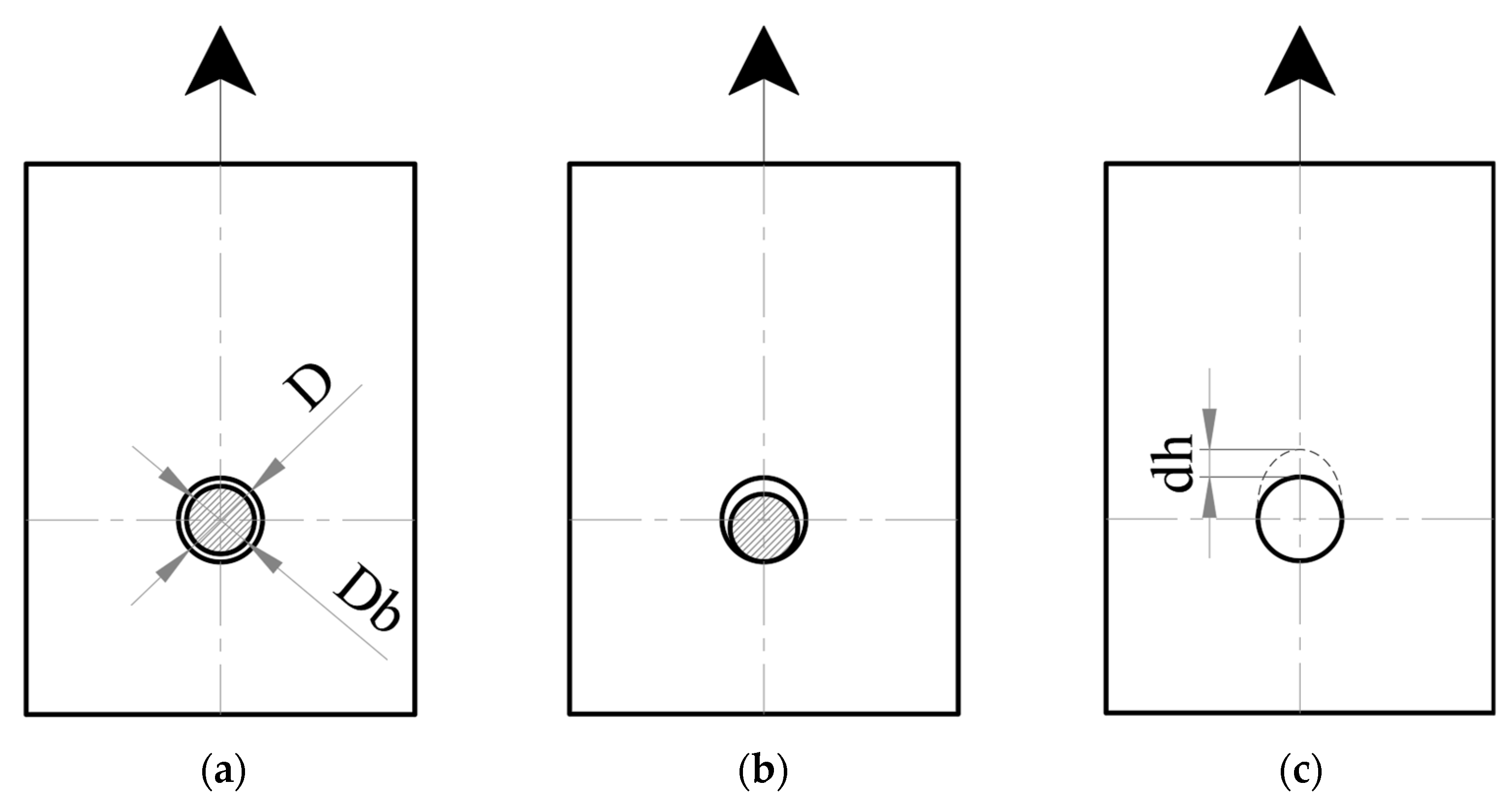
2.3. Effect of Bolt Clearance and Interface Condition

As seen in Figure 6a, the holes are milled with a diameter slightly greater than the bolt diameter (Db) for ease of installation. Bolt clearance is the difference between the hole diameter and the bolt diameter. At the early loading stages, the bolt assembly parts slide until the bolt shank touches the hole surface, Figure 6a. After that, the hole starts to be loaded and bolt extension (dh) takes place, Figure 6c. Cooper and Turvey [7] found that the load–displacement response of a single lapped joint has a small initial movement or displacement despite the case of tight fitting of the bolt.
McCarthy et al. [41] studied the clearance effect of the bolt-hole on the stiffness and strength of single-lapped joints. CFRP plates with different stacking sequences were considered in this study. Samples with different bolt-hole clearance values and bolt types were tested. The values of bolt-hole clearance ranged between 0 μm and 240 μm. It was found that increasing the clearance causes a reduction in the stiffness of the joint and increases the maximum strain of all joint cases. The bolts with finger tightening, which had a very low BCF, revealed a relationship between the strength and the clearance. This behavior did not appear in the case of countersunk bolts and the case of tightened bolts.
Lawlor, McCarthy, and Stanley [42] studied the load-displacement relation of the bolted joints. Results showed that there are linear and nearly linear regions. The clearance showed a trivial effect on the failure strength in the case of the CBJ. All joints failed initially due to the same load when the clearance increased, and the maximum displacement decreased while the stiffness decreased. The relations between the bearing strain and bearing stress were presented. It was found that the clearance has a negligible effect on the ultimate strength of the protruding bolt head joints while the influence was significant on the maximum strain due to the massive damage caused by the bolt bearing stress. The bolt-hole clearance significantly affects the joint stiffness and ultimate strain, while its effect on the joint strength is insignificant. The clearance caused a lag in the appearance of the load, which can be considered an important factor in the joints with multiple bolts.
Zhai et al. [43] studied the interface condition of the CBJ including shimming and interface gap on the bearing response of single-lap, countersunk composite-aluminum bolted joints. The specimens were made from T700/3068 CFRP laminate joined to an aluminum alloy plate. Shims consisting of both solid and liquid components were taken into account and compared. Shimming’s effect on the distribution of surface strain and out-of-plane deformation of the joints was assessed using 3D digital image correlation. It is found that the shimming condition has a significant impact on the bearing response of single-lapped, countersunk, composite-aluminum bolted joints. Single-lap countersunk composite-aluminum joints’ bearing performance is significantly reduced when there is an interface gap. The countersunk hole was made to lose support from the aluminum plate at the shear plane due to the gap. Shim thickness increases result in lower bearing stiffness and bearing strength and intensify the loading eccentricity of single-lapped joints. The increased joint bending stiffness of the specimen with solid shim, which benefits from the high tensile modulus of solid peel-able fiberglass shim, results in a little improvement in bearing performance.

3. Effect of Bolt Tightening Torque

Friction-type connections have proven efficient in enhancing the behavior of metallic bolted joints [44]. Several experimental and numerical works studied the effect of bolt-tightening torque on the stiffness and strength of the CBJs [11,26,45,46,47,48,49,50,51]. Figure 7 shows the load transfer mechanism of the pure friction type connection. The value of the normal stress (σCF) and shear stress (τCF) between the washer and the bolt head control the behavior of the friction-type connection. It is very difficult in FRP composite bolted joints to achieve the amount of BCF required to behave as a pure friction joint due to the low stiffness and strength in the thickness direction. In CBJs, it was found that a hybrid bearing friction mechanism takes place [26].
Claire et al. [39] investigated the effect of lay-up and tightening torque on the CFRP CBJs. Three different symmetric laminates with different lay-ups were used in the experimental study. The initial and ultimate bearing stresses were significantly affected by the BCF according to the bearing stress vs. hole extension curves and the bearing stress–strain curves. The same bolt-hole extension was evaluated from both the quasi-isotropic and angle ply lay-ups which was greater than the extension of the bolt-hole of cross-ply samples. Both the initial and maximum bearing stresses were increased as a result of BCF. Both the initial stiffness and the bolt-hole extension significantly decreased as the tightening torque increased.
Park [40] studied the impact of BCF on the bearing delamination strength and the ultimate bearing strength of bolted CFRP joints. Orthotropic and quasi-isotropic laminate stacking sequences with four different values of bolt-tightening torques were considered. The BCF had a significant effect on the ultimate bearing and the delamination load of the CBJ. The ultimate bearing strength increases to saturation as the BCF increases, but the delamination bearing strength increases gradually. The interlinear cracks and delamination were both delayed by the BCF. As the BCF increased, a progressive failure mode was evaluated.
Sun et al. [52] experimentally studied lateral constraint’s effect on the BF of the CFRP CBJ. CFRP coupons were studied for various BCF values and washer sizes. As the tensile load was incrementally applied to the CBJ, the BCF was monitored. By increasing the tension load of the joint, the Poisson ratio effect increased the BCF and the lateral constraints. The strength of the pinned joints was lower than the strength of CBJs due to the lateral BCF.
The effects of BCF on the net tension failure of the CBJ were studied experimentally by Yan et al. [53]. The failure modes and the tensile strength of both the bolt-filled hole and the open bolt hole were studied for CFRP composite plates. The washer size effect on the net-tension failure and the net tensile strength were also explored. X-ray radiographs were used to inspect the damage progress and the modes of failure inside the composite. The composite laminate joints with bolt filled-hole were subjected to delamination and splitting of the fiber matrix because of its sensitivity to the clamping effect of the bolt. By increasing the BCF, the tensile strength decreases for the filled-hole case. The BCF reduced the tensile strength of the CBJ by about 20%. When the washer-to-bolt-hole diameter ratio was less than 2, it reduced the tensile strength of the filled-hole samples. On the other hand, the BCF was found to increase the tensile strength of the CBJs.
Khashaba et al. [54] investigated the effect of washer size and bolt tightening torque on the progressive failure of GFRP CBJ bearings. A numerical study of increasing damage was conducted to understand the failure behaviors. Under constant tightening torque, it was found that by decreasing the washer sizes, the joint stiffness increases. This occurs as a result of an increase in clamping pressure based on a smaller washer contact area. The inspection of the load-displacement curves of the joints with finger-tightened bolts showed the minimum stiffness associated with non-linear behavior due to the development of internal composite damage. The common failure mechanism was in a sequence, delamination, and net tension failure at 90° laminate, shear out failure at 0° layers, and catastrophic final failure due to the bearing of ±45° layers.
Kostreva [55], investigated the torque limit in a composite single-lapped joint, CFRP laminates were used with three different through-hole diameters. To supplement the data from the standard test, acoustic emission (AE) nondestructive testing was applied. As a result of the tests, it was determined that the composite plates under investigation did not fail before the bolt. Furthermore, it was considered that the 0.125-inch bolts would not provide a large enough tensile load to cause failure once it was shown that the 0.5-inch bolt could not fail the plates, thus these tests were not performed.
To predict the effect of BCF on the initiation and growth of delamination damage in mechanical joints of composite laminates, a 3D FE model was created by Ataş, Mohamed, and Soutis, [56]. The widely used cosine stress distribution model and the X-ray images from the literature, respectively, have been utilized to verify the stress distribution around the pin-loaded hole and delamination prediction capabilities. It was indicated that the effect of the Mode I component on the onset and growth of delamination is insignificant without the modeling of the in-plane failure modes (transverse ply cracking and axial splitting); of course, in the case of a CBJ with a certain BCF, Mode I fracture is also restrained.
Based on the review it can be concluded that BCF is one of the most effective design parameters. It can enhance the stiffness and the strength of the joint and its effectiveness can be improved by using an appropriate washer size.

4. Progressive Failure Mechanism in Cbjs

Lawlor, Stanley, and McCarthy investigated the change in the damage mechanism of CFRP CBJs due to bolt-hole clearances [57]. In the study, single bolt single lapped joints were analyzed while subjected to tensile load. The load vs. displacement curve was reported to determine the maximum bearing and failure loads of the bolted connections.
It was observed, in the case of large clearance, that there was a delay in the load vs. displacement data, a significant loss in the stiffness, a small slope in the linear part, and the joints failed due to bolt failure. However, in the case of small clearance, the bolt did not fail, but a large displacement was recorded. Furthermore, the inspection of the failed samples shows significant damage on the shear plane in both large and small clearances.
The failure mechanisms of CFRP CBJs were studied under tensile loading by Girard et al. [58]. The effects of stacking sequence and BCF on the mechanism of failure were studied. Digital photography and optical microscopy were used to evaluate the external and internal macroscopic damage. It was found that the direction of the fiber surrounding the bolt hole had affected the start of the failure. The inter-laminar shear delamination, matrix cracking, and compressive failure were the major failure modes in all designs. Shear cracks were seen on the laminate’s surface in the case of the tight CBJs i.e., finger, and torque tightened. Severe internal damage was observed in the micrographs of the same specimens over the whole bearing zone. Different damage patterns were observed between the angle ply and the quasi-isotropic laminates for the same value of BCF. Several shear cracks were observed over the bearing zone in the case of the quasi-isotropic laminate. The more severe damage was found distributed over a large area in the case of the angle-ply composite bolted plate. The prominent shear cracks were found at a distance from the bearing plane and reached the laminate surface when higher stresses are applied to the specimens.
Greenhalgh et al. studied the bearing failure processes of CFRP laminates to characterize the impact of drilling damage on the failure mechanisms [20]. The early damage processes were longitudinal splitting tangential to the lateral extents of the hole. This splitting determined the degree of subsequent bearing damage development and increased the in-plane micro-buckling in the bearing damage zone.
The double and single-lapped joint bearing strength and failure mechanism in composite joints were investigated by Xiao [59]. The bearing load at which the bolt-hole achieved a displacement of 4% of the pin diameter was used to calculate the bearing strength. The maximum load value of the load-displacement data was considered the ultimate failure load. Before the displacement reached 4% of the bolt diameter, it was observed that there were two main regions in the load-displacement curve; a linear region followed by a non-linear region.
This was due to the micro-damage activation in the tested coupon. While the samples are tested under static, the AE and the load-displacement data were monitored simultaneously to make the fracture analysis of the samples. Once the nonlinear behavior started, the AE signal sharply changed as an indication of the beginning of the damage. Furthermore, to make an investigation of the failure mechanism, pictures of the specimen surfaces and X-ray radiographs of the area bearing damage were used. By increasing the tensile load, progress was observed in the local delamination under the washer, the out-of-plane shear cracks, and the fiber matrix splitting cracks. The final failure of the CBJs is controlled by these failure modes. Further, the two-bolt joint was studied to investigate the bearing load ratio of each of the bolts. Load cells and extensometers were used at each bolt-hole to record the behavior of each bolt. It was found that the nonlinear load elongation behavior of each bolt was significantly different. The damage analysis, which was performed by using SEM and X-ray radiography, indicated that the difference in the load shares of each bolt is responsible for the variation in the compressive damage state around the holes.
The bearing response and BF mechanism of CBJs were experimentally studied by Wang, Hung, and Chang [60] under the effect of BCF. Two bearing damage behaviors were characterized according to the state of the lateral support: A pure BF, in which the joint had no lateral support, and a bolt BF, in which the joint contained lateral supports with various values of BCF. To depict the pure bearing damage, semi-circular notched specimens with a special design were used. The BCF in the bolts was monitored using a load cell. Two different laminate thicknesses and three different bolt-hole diameters were used in the study. The microscope and X-ray radiography were used to inspect the failure of the specimens. It was found that the main cause of the BF was the shear cracks resulting from the compression failure. Catastrophic BF was noticed in the joints, which do not have a lateral constraint. It was found that the critical bearing distance (δc) (the distance until the onset of the catastrophic failure) depended on the thickness of the laminate and that the lamina directions had no effect on the critical bearing distance. Bolt lateral support was found to decrease catastrophic failure and increase the bearing strength.
The effect of the loose-fit fasteners was studied by Tong [61]. Two extreme positions were used to investigate the effect of the BF in the double-lapped bolted composite joints. Placing the washers in extreme positions in the opposite loading direction prevented the existence of an unconstrained gap between the washers and the shank. Placing them in the loading direction, on the other hand, created an unconstrained gap between the bolt shank and the washers. It was found that there was no difference in the ultimate failure loads between the CBJs with an unconstrained gap and those joints having no unconstrained gap, while the CBJs with no unconstrained gap showed a higher initial failure load.
Crosky et al. [62] studied different strategies to improve the bearing strength of the bolted composite joints such as matrix stiffening by nano-reinforcement, fiber steering, and through-thickness reinforcement using z-pins. Although the stiffness of the matrix was enhanced due to the addition of clay nanoparticles to the matrix resin, the premature failure mode was different from the case of the pure matrix, and the joint bearing strength was reduced. Finite element analysis showed that using two sets of steered fibers in tensile and compressive principal stress direction improved the bearing strength by 36%. The ultimate bearing load was increased by 7%, while the same bearing strength remained the same for the case of using the through-thickness reinforcement with the Z-pins.
The effect of bolt-hole clearance on the load transfer in multi-bolt FRP joints was studied by Stanley, McCarthy, and Lawlor [63]. Three-bolt single-lapped joint was the case under investigation. The samples were fabricated from graphite/epoxy HTA/6376, with a quasi-isotropic stacking sequence. It was found in this study that substantial effects on load distribution can be found due to the relatively small amounts of clearance. For the case of three bolts, it is known that the middle bolt typically has the lower shear force so, usually, the damage is not expected to happen around it. The outer bolts carry the higher forces, and usually, the damage happens around them. However, due to the clearance, the load can be shifted to the middle bolt, which can potentially cause an unexpected failure mode.
Xiao et al. [64] developed a progressive fatigue model for bolted composite joints by integrating stress-cycle S-N-based crack initiation with Paris-type (da/dN) based damage propagation. A modified cohesive model for fatigue captures the rate of damage increase caused by fracture energy and the S-N-based strength degradation in an elementwise manner. The applicability of the proposed composite fatigue model based on the coupling of S-N and da/dN data was demonstrated.
Lua et al. [65] performed a study of the failure process of composite bolted joints combining an in situ X-ray, computed tomography (CT) approach with SSB test. Based on the conventional CDM technique and a static bearing model, a physics-informed modeling approach was developed. A study was done on how the limitation affected the kinking band angle and compressive strength. Through a comparison of the stress–strain response and accompanying failure patterns, the modeling technique was confirmed using SSB testing.
Lua et al. [66] characterized the physical mechanisms underlying bearing failure in composite joints with countersunk bolts using X-ray computed tomography (XCT) and a bearing failure model developed for the ABAQUS FE code. In comparison to light-weight CFRP composite laminates, the high-fidelity XCT was explored for the detection and characterization of bearing failure in bolted composite components without removing the fastener, which could introduce significant scatter in the XCT scan. Based on a longitudinal and transverse micromechanics assessment, a static bearing model was also developed for the damaged material response in the bearing region. The predicted load-displacement response and experimental measurements were compared, and the simulated failure patterns and XCT images were examined. Based on the current SSB test, a new design was set-up utilizing the improved analytical tool to obtain a dominating bearing failure mechanism.
Ahmet Cana and Ahmet Meram [67] studied the dynamic behavior of CFRP joints. Impact tests on bolted composite laminates with screw sizes ranging from M6 to M14 and varied pitch screws were carried out for this purpose. The bolt was threaded through the composite plate and the bolt head was subjected to impact.
The load deflection, peak force, and failure mechanism are affected by the dynamic loading of screwed joints. As the pitch increased, the damage mechanism changed from interlaminar delamination to push-out delamination. In addition, the maximum failure load increases for a metric screw thread size by increasing the pitch size.
It can be concluded that the BF of CBJ is a progressive noncatastrophic failure mode which makes it favorable for the designer. The joint width-to-bolt diameter ratio is the most effective parameter and should be kept at less than 4. Bearing failure is caused by the pressure exerted by the bolt shank on the composite plate hole which produces delamination, fiber buckling, splitting, and microcracks in the composite materials. All these behavior can be reduced by using sufficient lateral restrain and BCF.

5. Conclusions

In this research, the previous works that describe the behavior of the composite bolted joint (CBJ), were presented, and summarized including the modes of failure of the CBJ, and the experimental works that explain the bearing failure (BF) of the CBJ.
The following conclusions were driven by this survey.
-
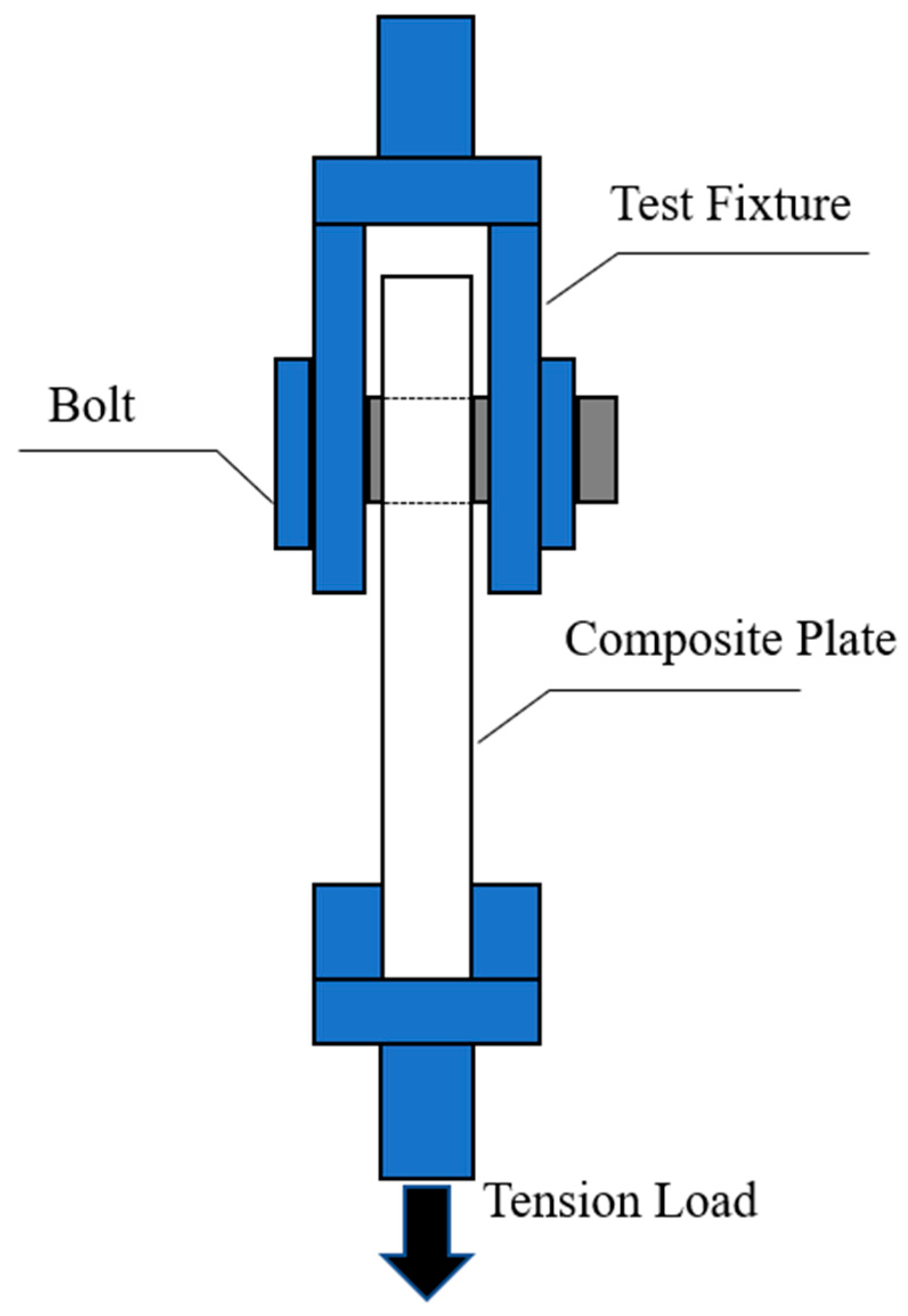
BJ has several favorable benefits such as the easy mantling and dismantling processes. However, it can be addressed as the most critical location in the structural element design. There are important factors that control the design of CBJ such as composite lay-up, joint geometry, the orientation of fiber, and clamping force.
-
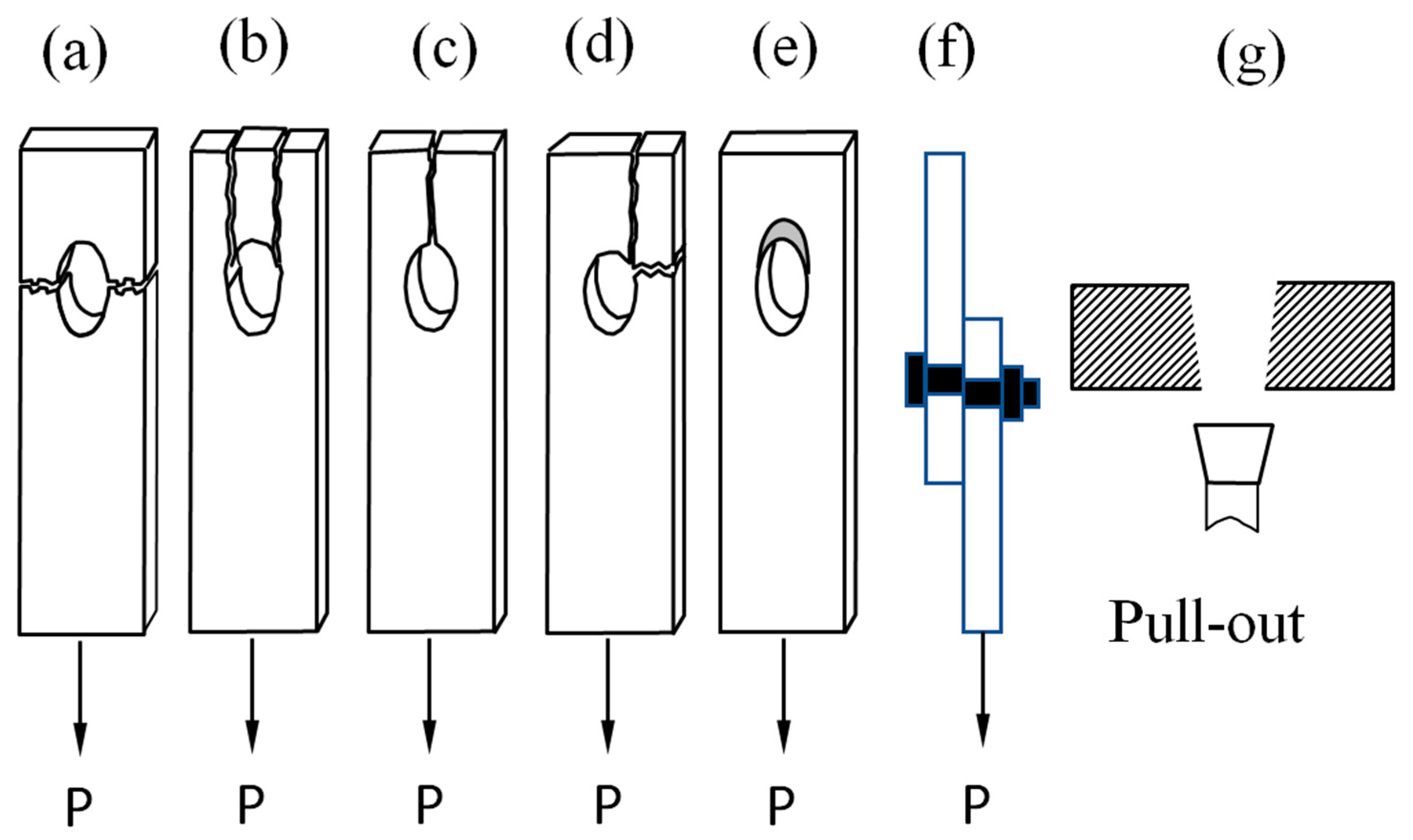
Increasing the joint width, and edge distance and selecting the suitable lay-up could help to avoid several catastrophic failure modes such as net tension, cleavage, and shear-out failure modes, and to achieve progressive bearing failure.
-
When the edge and the width ratios are less than 4, the BF was the primary failure mode. When these ratios were less than 4, a mixture of net tension and shear-out failures was found.
-
The bearing stress–strain curves could mainly be divided into three different zones: the initial sliding zone, the linear bearing zone before the damage initiation, and a nonlinear zone after damage.
-
Small-width joints showed more yield behavior than the joints with standard dimensions with an insignificant effect of the end distance on the stiffness.
-
It was found that increasing the clearance causes a reduction in the stiffness of the joint and increases the maximum strain of all joint cases. The clearance showed a trivial effect on the failure strength in the case of the CBJ.
-
The angle-ply stacking sequence had the lowest initial stiffness and the cross-ply stacking sequence had the maximum initial stiffness. Layering at a 45° angle increased the bearing strength however, the layers with a 90° direction significantly increased the delamination bearing strengths.
-
Using two sets of steered fibers in the primary stress directions of compression and tensile improved the bearing strength by 36%. When applying the through-thickness reinforcement with Z-pins, the maximum bearing load rose by 7%. In addition, composites with three-dimensional woven fiber reinforcement have exceptional strength under off-axis bearing loads.
-
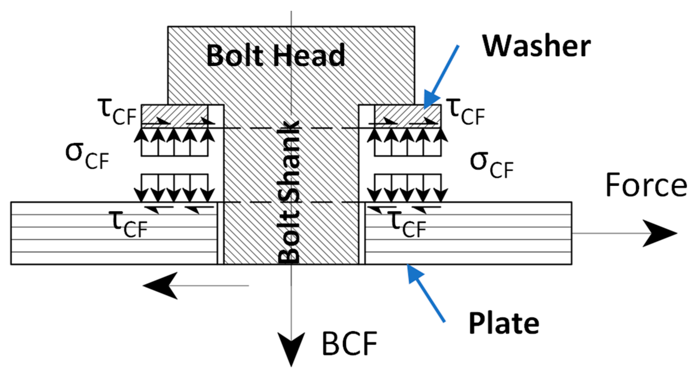
The BCF was found to increase the tensile strength of the CBJs and delay both interlinear cracks and delamination which leads to a progressive failure mode.
-
The strength of the pinned joints was lower than the strength of CBJs due to the lateral BCF. In addition, by increasing the tension load of the joint, the Poisson ratio effect increased the BCF and the lateral constraints.
-
At constant BCF, decreasing the washer-to-bolt-hole diameter ratio to less than 2 leads to a decrease in the tensile strength of the CBJs. On the other hand, the BCF was found to increase the tensile strength of the CBJs.
-
The BF is a process of compressive damage accumulation that occurs through four stages of damage: damage onset, damage growth, local fracture, and structural fracture. Fiber micro-buckling, matrix cracking, delamination, and out-of-plane shear cracking are some of the main features of BF.

Author Contributions

Conceptualization, A.E.-S. and H.S.; software, F.A., A.H., N.G. and A.E.-S.; formal analysis, A.E.-S., A.H. and F.A.; investigation, A.E.-S., A.H. and N.G.; data curation, A.E.-S., A.H. and F.A.; writing—original draft preparation, A.E.-S., A.H. and N.G.; writing—review and editing, H.S. and F.A.; visualization, A.E.-S. and A.H.; supervision, H.S. and A.E.-S.; project administration, H.S. and A.E.-S. All authors have read and agreed to the published version of the manuscript.

Funding

This research received no external funding.

Data Availability Statement

Data is contained within the article.

Conflicts of Interest

The authors declare no conflict of interest.

References

  1. Gray, P.J.; McCarthy, C.T. A Global Bolted Joint Model for Finite Element Analysis of Load Distributions in Multi-Bolt Composite Joints. Compos. Part B Eng. 2010, 41, 317–325. [Google Scholar] [CrossRef]
  2. Kradinov, V.; Madenci, E.; Ambur, D. Combined In-Plane and Through-the-Thickness Analysis for Failure Prediction of Bolted Composite Joints. In Proceedings of the 45th AIAA/ASME/ASCE/AHS/ASC Structures, Structural Dynamics & Materials Conference, Palm Springs, CA, USA, 19–22 April 2004; American Institute of Aeronautics and Astronautics: Plam Springs, CA, USA, 2004. [Google Scholar]
  3. Camanho, P.P.; Matthews, F.L.; Running, D.M.; Ligon, J.B.; Miskioglu, I.; Camanho, P.P.; Matthews, F.L. A Progressive Damage Model for Mechanically Fastened Joints in Composite Laminates. J. Compos. Mater. 1999, 33, 2248–2280. [Google Scholar] [CrossRef]
  4. Virupaksha, V.L. Behavior of Fastened and Adhesively Bonded Composites under Mechanical and Thermomechanical Loads; Oakland University: Rochester, MI, USA, 2008. [Google Scholar]
  5. Camanho, P.P.; Bowron, S.; Matthews, F.L. Failure Mechanisms in Bolted CFRP. J. Reinf. Plast. Compos. 1998, 17, 205–233. [Google Scholar] [CrossRef]
  6. Sun, H.-T.; Chang, F.-K.; Qing, X. The Response of Composite Joints with Bolt-Clamping Loads, Part I: Model Development. J. Compos. Mater. 2002, 36, 47–67. [Google Scholar] [CrossRef]
  7. Cooper, C.; Turvey, G.J. Effects of Joint Geometry and Bolt Torque on the Structural Performance of Single Bolt Tension Joints in Pultruded GRP Sheet Material. Compos. Struct. 1995, 32, 217–226. [Google Scholar] [CrossRef]
  8. ASTM International Standard Test Method for Bearing Response of Polymer Matrix Composite Laminates. Annu. B. ASTM Stand. 2013, i, 1–18. [CrossRef]
  9. Walker, S.P. Thermal Effects on the Bearing Behavior of Composite Joints; University of Virginia: Charlottesville, VA, USA, 2001. [Google Scholar]
  10. Hutchinson, A. Advanced Materials Engineering and Joining-Mechanical Connections in Polymer Composite Materials; Oxford Brookes University: Oxford, UK, 2000. [Google Scholar]
  11. Vangrimde, B.; Boukhili, R. Bearing Stiffness of Glass Fibre-Reinforced Polyester: Influence of Coupon Geometry and Laminate Properties. Compos. Struct. 2002, 58, 57–73. [Google Scholar] [CrossRef]
  12. Belardi, V.G.; Fanelli, P.; Vivio, F. Analysis of Multi-Bolt Composite Joints with a User-Defined Finite Element for the Evaluation of Load Distribution and Secondary Bending. Compos. Part B Eng. 2021, 227, 109378. [Google Scholar] [CrossRef]
  13. Sajid, Z.; Karuppanan, S.; Kee, K.E.; Sallih, N.; Shah, S.Z.H. Bearing Performance Improvement of Single-Lap, Single-Bolt Basalt Composite Joints by Locally Strengthening the Joint Location Using Carbon Fibre. Thin-Walled Struct. 2022, 180, 109873. [Google Scholar] [CrossRef]
  14. Sajid, Z.; Karuppanan, S.; Sallih, N.; Kee, K.E.; Shah, S.Z.H. Role of Washer Size in Mitigating Adverse Effects of Bolt-Hole Clearance in a Single-Lap, Single-Bolt Basalt Composite Joint. Compos. Struct. 2021, 266. [Google Scholar] [CrossRef]
  15. Delzendehrooy, F.; Akhavan-Safar, A.; Barbosa, A.Q.; Carbas, R.J.C.; Marques, E.A.S.; da Silva, L.F.M. Investigation of the Mechanical Performance of Hybrid Bolted-Bonded Joints Subjected to Different Ageing Conditions: Effect of Geometrical Parameters and Bolt Size. J. Adv. Join. Process. 2022, 5, 100098. [Google Scholar] [CrossRef]
  16. Li, X.; Cheng, X.; Guo, X.; Liu, S.; Wang, Z. Tensile Properties of a Hybrid Bonded/Bolted Joint: Parameter Study. Compos. Struct. 2020, 245, 112329. [Google Scholar] [CrossRef]
  17. Qin, X.; Cao, X.; Li, H.; Zhou, M.; Ge, E.; Li, Y. Effects of Countersunk Hole Geometry Errors on the Fatigue Performance of CFRP Bolted Joints. Proc. Inst. Mech. Eng. Part B J. Eng. Manuf. 2022, 236, 337–347. [Google Scholar] [CrossRef]
  18. Liu, L.; Wang, X.; Wu, Z.; Keller, T. Optimization of Multi-Directional Fiber Architecture for Resistance and Ductility of Bolted FRP Profile Joints. Compos. Struct. 2020, 248, 112535. [Google Scholar] [CrossRef]
  19. Li, M.; Liu, Z.; Yan, R.; Lu, J.; Guedes Soares, C. Experimental and Numerical Investigation on Composite Single-Lap Single-Bolt Sandwich Joints with Different Geometric Parameters. Mar. Struct. 2022, 85, 103259. [Google Scholar] [CrossRef]
  20. Greenhalgh, E.S.; Canturri, C.; Katafiasz, T.J. Fractographic Study into the Effect of Drilling Damage on Bearing Mechanisms and Performance in Carbon-Fibre Epoxy Composites. Eng. Fail. Anal. 2021, 129, 105638. [Google Scholar] [CrossRef]
  21. Zhang, Y.; Zhou, Z.; Pan, S.; Tan, Z. Comparison on Failure Behavior of Three-Dimensional Woven Carbon/Carbon Composites Joints Subjected to out-of-Plane Loading at Room and High Temperature. Compos. Commun. 2021, 23, 100567. [Google Scholar] [CrossRef]
  22. Cao, Y.; Zuo, D.; Zhao, Y.; Cao, Z.; Zhi, J.; Zheng, G.; Tay, T.E. Experimental Investigation on Bearing Behavior and Failure Mechanism of Double-Lap Thin-Ply Composite Bolted Joints. Compos. Struct. 2021, 261, 113565. [Google Scholar] [CrossRef]
  23. Li, W.; Guo, S.; Giannopoulos, I.K.; He, S.; Liu, Y. Strength Enhancement of Bonded Composite Laminate Joints Reinforced by Composite Pins. Compos. Struct. 2020, 236, 111916. [Google Scholar] [CrossRef]
  24. Hou, L.; Liu, D. Size Effects and Thickness Constraints in Composite Joints. J. Compos. Mater. 2003, 37, 1921–1938. [Google Scholar] [CrossRef]
  25. Barbero, E.J. Introduction to Composite Materials Design. Hum. Fertil. Camb. Engl. 2011, 73, 520. [Google Scholar] [CrossRef]
  26. El-Sisi, A.E.-D.; Sallam, H.E.-D.; Salim, H.; El-Husseiny, O. Structural Behavior of Hybrid CFRP/Steel Bolted Staggered Joints. Constr. Build. Mater. 2018, 190, 1192–1207. [Google Scholar] [CrossRef]
  27. Oh, J.H.; Kim, Y.G.; Lee, D.G. Optimum Bolted Joints for Hybrid Composite Materials. Compos. Struct. 1997, 38, 329–341. [Google Scholar] [CrossRef]
  28. Aktas, A.; Husnu Dirikolu, M. An Experimental and Numerical Investigation of Strength Characteristics of Carbon-Epoxy Pinned-Joint Plates. Compos. Sci. Technol. 2004, 64, 1605–1611. [Google Scholar] [CrossRef]
  29. Aktaş, A. Bearing Strength of Carbon Epoxy Laminates under Static and Dynamic Loading. Compos. Struct. 2005, 67, 485–489. [Google Scholar] [CrossRef]
  30. Warren, K.C.; Lopez-Anido, R.A.; Goering, J. Behavior of Three-Dimensional Woven Carbon Composites in Single-Bolt Bearing. Compos. Struct. 2015, 127, 175–184. [Google Scholar] [CrossRef]
  31. Xiao, Y.; Ishikawa, T. Bearing Strength and Failure Behavior of Bolted Composite Joints (Part I: Experimental Investigation). Compos. Sci. Technol. 2005, 65, 1022–1031. [Google Scholar] [CrossRef]
  32. Ascione, F.; Feo, L.; MacEri, F. On the Pin-Bearing Failure Load of GFRP Bolted Laminates: An Experimental Analysis on the Influence of Bolt Diameter. Compos. Part B Eng. 2010, 41, 482–490. [Google Scholar] [CrossRef]
  33. Egan, B.; McCarthy, C.T.; McCarthy, M.A.; Gray, P.J.; O’Higgins, R.M. Static and High-Rate Loading of Single and Multi-Bolt Carbon-Epoxy Aircraft Fuselage Joints. Compos. Part A Appl. Sci. Manuf. 2013, 53, 97–108. [Google Scholar] [CrossRef] [Green Version]
  34. Sevkat, E.; Brahimi, M.; Berri, S. The Bearing Strength of Pin Loaded Woven Composites Manufactured by Vacuum Assisted Resin Transfer Moulding and Hand Lay-up Techniques. Polym. Polym. Compos. 2012, 20, 321–332. [Google Scholar] [CrossRef]
  35. Starikov, R.; Schön, J. Quasi-Static Behaviour of Composite Joints with Countersunk Composite and Metal Fasteners. Compos. Part B Eng. 2001, 32, 401–411. [Google Scholar] [CrossRef]
  36. Aktas, A.; Dirikolu, M.H. The Effect of Stacking Sequence of Carbon Epoxy Composite Laminates on Pinned-Joint Strength. Compos. Struct. 2003, 62, 107–111. [Google Scholar] [CrossRef]
  37. Vangrimde, B.; Boukhili, R. Descriptive Relationships between Bearing Response and Macroscopic Damage in GRP Bolted Joints. Compos. Part B Eng. 2003, 34, 593–605. [Google Scholar] [CrossRef]
  38. Ahmad, H.; Johnson, W.S.; Counts, W.A.; Hafiz Ahmad, W.S.; Johson, W.A.C. Evaluation of Bolt Bearing Behavior of Highly Loaded Composite Joints at Elevated Temperature. J. Compos. Mater. 2003, 37, 559–571. [Google Scholar] [CrossRef]
  39. Girard, C.; Dano, M.-L.; Picard, A.; Gendron, G. Bearing Behavior of Mechanically Fastened Joints in Composite Laminates--Part I: Strength and Local Strains. Mech. Adv. Mater. Struct. 2003, 10, 1–21. [Google Scholar] [CrossRef]
  40. Park, H.-J.J. Effects of Stacking Sequence and Clamping Force on the Bearing Strengths of Mechanically Fastened Joints in Composite Laminates. Compos. Struct. 2001, 53, 213–221. [Google Scholar] [CrossRef]
  41. McCarthy, M.A.; Lawlor, V.P.; Stanley, W.F.; McCarthy, C.T. Bolt-Hole Clearance Effects and Strength Criteria in Single-Bolt, Single-Lap, Composite Bolted Joints. Compos. Sci. Technol. 2002, 62, 1415–1431. [Google Scholar] [CrossRef]
  42. Lawlor, V.P.; McCarthy, M.A.; Stanley, W.F. Experimental Study on Effects of Clearance on Single Bolt, Single Shear, Composite Bolted Joints. Plast. Rubber Compos. 2002, 31, 405–411. [Google Scholar] [CrossRef]
  43. Zhai, Y.; Li, D.; Li, X.; Wang, L. An Experimental Study on the Effect of Joining Interface Condition on Bearing Response of Single-Lap, Countersunk Composite-Aluminum Bolted Joints. Compos. Struct. 2015, 134, 190–198. [Google Scholar] [CrossRef]
  44. Sallam, E.M.; El-Sisi, E.A.; Matar, E.B.; El-Hussieny, O.M. Effect of Clamping Force and Friction Coefficient on Stress Intensity Factor of Cracked Lapped Joints. Eng. Fail. Anal. 2011, 18, 1550–1558. [Google Scholar] [CrossRef]
  45. Hu, J.; Zhang, K.; Cheng, H.; Qi, Z. Mechanism of Bolt Pretightening and Preload Relaxation in Composite Interference-Fit Joints under Thermal Effects. J. Compos. Mater. 2020, 54, 4929–4946. [Google Scholar] [CrossRef]
  46. Hu, J.; Zhang, K.; Cheng, H.; Qi, Z. An Experimental Investigation on Interfacial Behavior and Preload Response of Composite Bolted Interference-Fit Joints under Assembly and Thermal Conditions. Aerosp. Sci. Technol. 2020, 103, 105917. [Google Scholar] [CrossRef]
  47. Feyzi, M.; Hassanifard, S.; Varvani-Farahani, A. Progressive Fatigue Behavior of Single-Lap Bolted Laminates under Different Tightening Torque Magnitudes. Proc. Inst. Mech. Eng. Part L J. Mater. Des. Appl. 2020, 234, 1303–1312. [Google Scholar] [CrossRef]
  48. Sajid, Z.; Karuppanan, S.; Shah, S.Z.H. Effect of Washer Size and Tightening Torque on Bearing Performance of Basalt Fiber Composite Bolted Joints. J. Nat. Fibers 2021, 19, 5910–5927. [Google Scholar] [CrossRef]
  49. El-Din El-Sisi, A.; El-Emam, H.; Salim, H.; El-Din Sallam, H.; El-Hussieny, O.M. Behavior of Single and Double Bolted Staggered Joint in Thick Composite Plates. In Proceedings of the American Society for Composites—31st Technical Conference, ASC 2016, Williamsburg, VA, USA, 19–22 September 2016. [Google Scholar]
  50. El-Sisi, A.E.-D.A.; El-Emam, H.M.; Salim, H.A.; Sallam, H.E.-D.M. Deformation and Load Transfer Analysis of Staggered Composite-Steel Lap Joints Subjected to Progressive Damage. Eng. Struct. 2020, 215, 110690. [Google Scholar] [CrossRef]
  51. Salim, H.; El-Din El-Sisi, A.; El-Emam, H.; El-Din Sallam, H. Maximum Clamping Force in Single and Double Lapped Joints. In Proceedings of the American Society for Composites—31st Technical Conference, ASC 2016, Williamsburg, VA, USA, 19–22 September 2016. [Google Scholar]
  52. Sun, H.-T.; Chang, F.-K.; Qing, X.; Mc, A.; Sun, H.-T.; Chang, F.-K.; Qing, X. The Response of Composite Joints with Bolt-Clamping Loads, Part II: Model Verification. J. Compos. Mater. 2002, 36, 69–92. [Google Scholar] [CrossRef]
  53. Yan, Y.; Wen, W.-D.; Chang, F.-K.; Shyprykevich, P. Experimental Study on Clamping Effects on the Tensile Strength of Composite Plates with a Bolt-Filled Hole. Compos. Part A Appl. Sci. Manuf. 1999, 30, 1215–1229. [Google Scholar] [CrossRef]
  54. Khashaba, U.A.; Sallam, H.E.M.; Al-Shorbagy, A.E.; Seif, M.A. Effect of Washer Size and Tightening Torque on the Performance of Bolted Joints in Composite Structures. Compos. Struct. 2006, 73, 310–317. [Google Scholar] [CrossRef]
  55. Kostreva, K. Torque Limit for Bolted Joint for Composites, Part B Experimentation; Embry-Riddle Aeronautical University: Daytona Beach, FL, USA, 2002. [Google Scholar]
  56. Ataş, A.; Mohamed, G.F.; Soutis, C. Effect of Clamping Force on the Delamination Onset and Growth in Bolted Composite Laminates. Compos. Struct. 2012, 94, 548–552. [Google Scholar] [CrossRef]
  57. Lawlor, V.P.; Stanley, W.F.; McCarthy, M.A. Characterisation of Damage Development in Single Shear Bolted Composite Joints. Plast. Rubber Compos. 2002, 31, 126–133. [Google Scholar] [CrossRef]
  58. Girard, C.; Dano, M.-L.; Picard, A.; Gendron, G. Bearing Behavior of Mechanically Fastened Joints in Composite Laminates--Part II: Failure Mechanisms. Mech. Adv. Mater. Struct. 2003, 10, 23–42. [Google Scholar] [CrossRef]
  59. Xiao, Y. Bearing Deformation Behavior of Carbon/Bismaleimide Composites Containing One and Two Bolted Joints. J. Reinf. Plast. Compos. 2003, 22, 169–182. [Google Scholar] [CrossRef]
  60. Wang, H.-S.; Hung, C.-L.; Chang, F.-K. Bearing Failure of Bolted Composite Joints. Part I: Experimental Characterization. J. Compos. Mater. 1996, 30, 1284–1313. [Google Scholar] [CrossRef]
  61. Tong, L. Bearing Failure of Composite Bolted Joints with Non-Uniform Bolt-to-Washer Clearance. Compos. Part A Appl. Sci. Manuf. 2000, 31, 609–615. [Google Scholar] [CrossRef]
  62. Crosky, A.; Kelly, D.; Li, R.; Legrand, X.; Huong, N.; Ujjin, R. Improvement of Bearing Strength of Laminated Composites. Compos. Struct. 2006, 76, 260–271. [Google Scholar] [CrossRef]
  63. Stanley, W.F.; McCarthy, M.A.; Lawlor, V.P. Measurement of Load Distribution in Multibolt Composite Joints, in Presence of Varying Clearance. Plast. Rubber Compos. 2002, 31, 412–418. [Google Scholar] [CrossRef] [Green Version]
  64. Xiao, J.; Cui, X.; Lua, J. A Progressive Fatigue Model for Bolted Composite Components. In Proceedings of the AIAA Scitech 2019 Forum, San Diego, CA, USA, 7–11 January 2019. [Google Scholar]
  65. Cui, X.; Xiao, J.; Lua, J.; Kariyawasam, S.; Smith, K.; Saathoff, C. A Micro-Macro Coupling and Physics Informed Modeling Approach for Bearing Failure with X-ray CT Characterization. In Proceedings of the AIAA Science and Technology Forum and Exposition, AIAA SciTech Forum 2022, San Diego, CA, USA, 3–7 January 2022. [Google Scholar]
  66. Cui, X.; Xiao, J.; Lua, J.; Kariyawasam, S.; Fulghum, E.; Saathoff, C. A Combined X-ray CT and Mechanistic Characterization of Bearing Failure Mechanisms in Bolted Composite Components. In Proceedings of the 77th Annual Vertical Flight Society Forum and Technology Display, FORUM 2021: The Future of Vertical Flight, Online, 10–14 May 2021. [Google Scholar]
  67. Can, A.; Meram, A. Dynamic Behavior of Screwed Joints for CFRP Composite Laminate Structures under Impact Loading. J. Manuf. Process. 2022, 75, 232–242. [Google Scholar] [CrossRef]
Figure 1. The bolted composite plate geometric parameters.
Civileng 03 00060 g001
Figure 2. Failure modes of CBJs: (a) net-tension, (b) shear-out, (c) transverse splitting, (d) cleavage, (e) bearing, (f) bolt, and (g) pull-out.
Civileng 03 00060 g002
Figure 3. Pin joint components.
Civileng 03 00060 g003
Figure 4. Geometric characteristics of composite-lapped joints: (a) Top view of a lapped joint, (b) side view of a single lapped joint, and (c) side view of a double lapped joint.
Civileng 03 00060 g004
Figure 5. Laminated plate lay-ups: (a) bi-directional lay-up, (b) angle-ply lay-up.
Civileng 03 00060 g005
Figure 6. Bolt hole locking; (a) bolt hole before locking, (b) bolt hole after locking, and (c) bolt hole deformation.
Civileng 03 00060 g006
Figure 7. Friction type connection load transfer.
Civileng 03 00060 g007
Publisher’s Note: MDPI stays neutral with regard to jurisdictional claims in published maps and institutional affiliations.

