Review

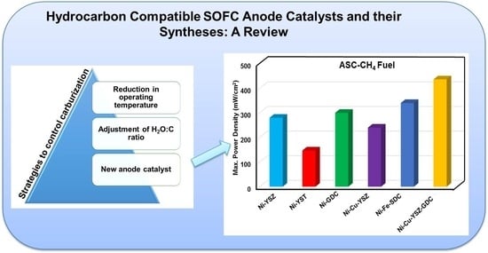
Hydrocarbon Compatible SOFC Anode Catalysts and Their Syntheses: A Review

by
Selvaraj Senthil Kumar
and
Singanahally ThippaReddy Aruna
*
Surface Engineering Division, Council of Scientific and Industrial Research-National Aerospace Laboratories, Bangalore 560017, India
*
Author to whom correspondence should be addressed.
Sustain. Chem. 2021, 2(4), 707-763; https://doi.org/10.3390/suschem2040039
Submission received: 31 October 2021 / Revised: 29 November 2021 / Accepted: 3 December 2021 / Published: 10 December 2021

Abstract

:
With the fast depleting rate of fossil fuels, the whole world is looking for promising energy sources for the future, and fuel cells are perceived as futuristic energy sources. Out of the different varieties of fuel cells, solid oxide fuel cells (SOFCs) are promising due to their unique multi-fuel operating capability without the need for an external reformer. Nonetheless, the state-of-the-art anode material Ni–YSZ undergoes carburization in presence of hydrocarbons (HCs), resulting in performance degradation. Several strategies have been explored by researchers to overcome the issue of carburization of the anode. The important strategies include reducing SOFC operating temperature, adjustment of steam: carbon ratio, and use of alternate anode catalysts. Among these, the use of alternate anodes is a promising strategy. Apart from the carburization issue, the anode can also undergo sulfur poisoning. The present review discusses carburization and sulfur poisoning issues and the different strategies that can be adopted for tackling them. The quintessence of this review is to provide greater insight into the various developments in hydrocarbon compatible anode catalysts and into the synthesis routes employed for the synthesis of hydrocarbon compatible anodes.

Graphical Abstract

1. Introduction

Fossil fuels such as gasoline, coal, and jet fuels are not renewable. Burning these limited fuel resources not only increases air pollution but also leads to a severe economic crisis. However, producing power from renewable sources still remains a challenge. Several eco-friendly power sources such as solar, wind, hydroelectric, and geothermal power sources can be used only in particular environments [1]. In the present scenario, batteries play a prominent role in portable devices. They are energy storage devices that have limited lifetimes and need to be disposed of in hazardous-waste landfills. In contrast, fuel cells are energy conversion devices that can exhibit near-zero emissions, are silent and effectual, and can operate in any environment [2,3].
Fuel cells are electrochemical devices that directly convert chemical energy into electrical energy, and fuel utilization efficiency of up to 85% can be achieved. Hence, it is possible to double the efficiency of power systems. Further, fuel cells can run in regenerative mode, i.e., they can also convert the excess electrical energy back to chemical energy. This feature enables fuel cells to couple with modern renewable technologies such as solar, wind, etc., to produce uninterrupted power. Thus, various types of fuel cell technologies are being pursued across the world. Among them, proton exchange membrane fuel cells (PEMFCs) and solid oxide fuel cells (SOFCs) are considered propitious technologies owing to their relatively higher efficiency. Further, the relatively striking level of development and potential for commercialization make these technologies the best alternatives to solve the future energy crisis. Thus, it is of paramount importance to adopt these fuel cells on a large scale for civil and military purposes [4,5].
PEMFC are low-temperature fuel cells that function in the temperature range of 70–90 °C, whereas SOFC operates at 800–1000 °C. The intermediate temperature (550–750 °C) SOFC (IT-SOFC) is still at the nascent stages of development. However, high-temperature SOFCs have several fundamental advantages over low-temperature fuel cells. These advantages include high power density and fuel tolerance. Further, it is worth mentioning that other fuel cells such as PEMFCs require controlled hydration of electrolyte membrane, and there is an obvious difficulty in maintaining the hydration in colder environments. This problem does not persist in SOFCs as they operate at relatively higher temperatures. Moreover, the heat from spent steam during SOFC operation can be utilized in other process requirements. As the name indicates, SOFC is made of all solids construction, and it operates at high temperatures and generates clean, efficient power from easy-to-transport fuels in lieu of pure hydrogen. Due to their low sensitivity to fossil fuels and their tolerance of impurities, SOFCs are extremely suitable for the use of HCs for auxiliary power units (APU) for vehicles as well as for stationary applications. Thus, SOFCs can find application in all types of environments including harsh environments encountered by aircraft, submarines, etc. [6,7,8,9]. Thus, the high efficiency and its ability to handle hydrocarbon (HC) fuels (including biofuels) have made the HC fuel-based SOFC one of the possible solutions to future energy needs.
There are seminal reviews on SOFCs, and readers can discern more information on SOFCs from them [10,11]. The contemporary SOFC single cells are fabricated in a planar design, and each cell consists of (a) dense 8 mol% yttria stabilized cubic zirconia (YSZ) as the electrolyte, (b) porous strontium doped lanthanum manganite (LSM) as the cathode, and (c) porous Ni–YSZ as the anode. Single cells are stacked using stainless-steel interconnections with channels for gas flow. The SOFCs are mostly designed either in anode- or electrolyte-supported configurations, and they are referred to as anode-supported cells (ASC) and electrolyte-supported cells (ESC) (Figure 1). The steps involved in the fabrication of ASC and ESC are shown in the flowchart (Figure 2). The tapecasting and screen printing are the most commercially viable techniques universally used for the fabrication of SOFC single cells. For ASC, the anode tapes containing NiO-YSZ and pore formers are stacked; over that, a thin YSZ tape is co-cast or a separate tape is placed over the NiO-YSZ, pressed, sintered, and followed by screen printing of cathode paste on the electrolyte and sintered again at a lower temperature than the anode sintering temperature. In the case of ESC, electrolyte YSZ or scandia-stabilized zirconia (ScSZ) tapes are stacked and sintered, followed by the screen printing of the anode and its sintering, followed by screen-printing of the cathode and, finally, sintering it again.
Though SOFC is capable of producing electricity using HCs as fuel, in the long run, the conventional anode of SOFC (Ni–YSZ) undergoes carburization in presence of HC fuels, which is catastrophic for the performance of SOFC. Very recently, a large number of reviews have been published on hydrocarbon-based SOFCs [11,12,13,14,15,16,17]. Dewa et al. [12] have reviewed the reforming catalysts for metal-supported SOFC. Wei et al. [13] have provided an account of perovskite materials for reforming CH4 in SOFCs. In a very recent review, Liu et al. [14] have summarized the fundamentals and challenges in using hydrocarbons directly in the upcoming proton-conducting SOFCs. Shabri et al. [15] have presented the strategies such as alloying and combining the ceramic component with mixing oxygen carrier that contains perovskite for using a cermet material as an anode to overcome the carbon deposition. Zhang et al. [16] have presented the progress of the catalyst layer materials for hydrocarbon-fueled SOFC and issues related to the use of those layers. Su et al. [17] have focused on the challenges and strategies associated with electrolytes, anodes, and cathodes for low-temperature SOFC. Shi et al. [18] have provided an account of anodic reactions in HC-based fuels and also discussed the properties and models of novel oxide anodes such as in situ exsolved metal catalysts.
The current review focuses on the issue of carburization and strategies adopted to control carburization. The underlining goal of this review is to discuss various alternate HC-compatible SOFC anode catalysts and their synthesis techniques. The issue of sulfur poisoning and strategies to control it are also presented.

2. Utilization of Hydrocarbon Fuels in SOFC

In the past two decades, direct internal reforming (DIR) in SOFC has been a topic of acute research. To circumvent the use of external reformers, efforts have been made to employ HCs directly in SOFCs. Since they are operated at high temperatures, the DIR of HC fuels can happen in the anode itself. While employing HCs as the fuel, it is generally assumed that SOFCs are operating on syngas (CO + H2) formed during reforming. Because of the high operating temperatures of SOFCs, HCs can be supplied to the anode right away without reforming externally. Therefore, the direct use of HCs could tremendously enhance fuel cell efficiency by evading the losses involved with external reformers. Higher molecular weight HCs undergo various elementary reactions at SOFC operating conditions. The elementary reactions are generally classified as (i) steam reforming, (ii) auto thermal reforming, (iii) partial oxidation (POX), and (iv) direct methane oxidation [19,20]. The reactions involved, along with their advantages and limitations, are summarized in Table 1.
Among the above reactions, DM-SOFCs possess maximum catalytic activity for the complete oxidation of methane. Further, complete electricity generation is possible without syngas cogeneration by using an anode catalyst that fosters CO2 and H2O production. It is mostly agreed that the carbonaceous adsorbates are easily oxidized by the chemisorbed oxygen species present on the metal surface. The surface oxygen for oxidation is made available from oxidants (H2O, CO2, and O2) or the lattice oxygen provided by oxide supports. Therefore, it is possible to control the carburization by controlling the reaction by feed composition. However, the present review is dedicated to understanding the basic ability of anode catalysts in controlling carburization

2.1. Carburization

HCs cannot be utilized directly in the state-of-the-art SOFCs as Ni-based anodes are not stable when HCs are employed as fuel due to the formation of carbon fibers, and details are presented in the next section.

2.1.1. Carburization Mechanism

The mechanism of carbon fiber formation involves the following steps: (i) carbon from the HC is deposited on the Ni surface, (ii) it undergoes dissolution into the bulk of the Ni, and (iii) it is precipitated as a fiber. The carbon fiber formation leads to Ni loss due to a process called ‘‘metal dusting’’, wherein Ni atoms are physically picked from the surface due to their entanglement with the growing carbon fibers. The metal dusting starts with the transfer of carbon from the carbon supersaturated environment (Carbon activity (Ac) > 1) to the metal surface. Subsequently, graphitic carbon deposits on the metal surface and forms graphitic planes (often perpendicular to the metal surface), resulting in the formation of a kind of channel between planes for transferring metal ions. Finally, the detached metal particles catalyze the filamentous carbon [21]. Due to the growth of carbon fibers, mechanical stresses are generated in the SOFC, resulting in its fracture [22,23,24].

2.1.2. Carburization Kinetics

Basically, three types of reactions are considered as the source of carbon deposition in the operating condition of SOFC while using methane and CO as fuels. They are
(i)
Methane cracking
CH 4   C + 2 H 2   Δ H 298 K = + 19   kJ mol 1
(ii)
Reduction of carbon monoxide
CO +   H 2 C +   H 2 O   Δ H 298 K = 131 kJ mol 1
(iii)
Boudouard reaction
2 CO C +   CO 2   Δ H 298 K = 172   kJ mol 1
Figure 3a shows that the Boudouard reaction is highly active below 800 °C and fades away above 800 °C, whereas, from Figure 3b, it is evident that the methane cracking reaction is favored above 800 °C [25]. Further, the equilibrium concentration of typical feed gas of SOFC over the temperature range of 0–1000 °C indicates minimal carbon deposits at 800 °C (Figure 4) [26]. However, it is difficult to decide upon the vulnerable conditions based on just the temperature and gas composition.
The carbon activity decreases with increasing temperature while the diffusivity of carbon in metal and carbon saturation concentration increases with temperature. Thus, in addition to temperature and gas composition, material property plays a key role in deciding the vulnerable condition. Dean et al. [27] have derived the following parameter to quantify the vulnerability based on material property and carbon activity:
N c = D c X c 1 A c
where
  • Nc—parameter to quantify carburization vulnerability
  • Dc—diffusivity of carbon in metal at a given temperature
  • Xc—maximum solubility of carbon in the metal
  • Ac—carbon activity.
The diffusion constant is directly proportional to the temperature. As the diffusion constant decreases to a greater extent than the increasing carbon activity with decreasing temperature, there is no impact of higher carbon activity felt at low temperatures. Diffusion is driven by the concentration gradient of carbon at the surface to the bulk of the metal. In order to convert carbon activity to a concentration of carbon, it is necessary to multiply it by the saturation concentration of carbon in metal. Thus, the diffusion coefficient, the carbon concentration and the activity coefficient are good indicators of the driving force to cause carbon to diffuse into the alloy.

2.1.3. Strategies to Control Carburization

So far, numerous approaches have been attempted to control or curtail the carburization issue. Most of those approaches can be classified as shown in Figure 5.
The first strategy to control carburization is reducing the operating temperature of SOFC. It is evident from Equation 4 that the diffusivity and carbon saturation concentration would be lower at the lower operating temperature of the SOFC (below 700 °C). However, the oxygen ion conduction also reduces with temperature. Further, the carbon activity increases with decreasing temperature. Hence, the SOFC has to be operated at a relatively higher current density to check the carbon deposition, which in turn would lead to high concentration polarization loss. Hence, this strategy may not be effective.
Secondly, the problem of carbon fiber formation on Ni can be circumvented by enriching the fuel with adequate amounts of steam to enable the removal of carbon at a faster rate compared to its deposition rate. The presence of steam would enable the methane steam reforming reaction in the anode and reduce the carburization. Usually, thermodynamic analysis is employed to anticipate the H2O:C ratios essential to circumvent carbon fiber formation. However, fibers are formed at much higher H2O:C ratios than the predicted values. This clearly shows that the stability of Ni anodes is dependent on the comparative rates of carbon deposition and its diminution.
The rate of carbon deposition with CH4 is comparatively low and, hence, CH4 can be internally reformed in SOFC by maintaining the H2O:C ratio as unity. Since carbon deposits faster on Ni in presence of higher HCs, higher H2O:C ratios have to be maintained to prevent carbon fibers formation. In this scenario, a higher amount of steam will result in fuel dilution and thereby reduce the SOFC efficiency. Further, steam enhances the formation of Ni(OH)2, which in turn destabilizes the anode. Above all, the thermal stress induced by the endothermic steam reforming reaction can damage the cell. This approach has not been widely used due to the destructive aftermath of fiber formation such as cell fracture and removal of Ni [28,29].
Another approach for direct utilization of HCs as fuel in SOFCs is to choose alternate anode materials that do not activate the formation of carbon fibers similar to Ni. The solubility of carbon in Cu, Ag, and Au is lower than Ni, Fe, Co, and Ru and does not result in fiber formation [30,31]. However, in general, polyaromatic species generated by gas-phase pyrolysis can deposit on the surface of any material; fortuitously, these deposits are not as damaging as that of fiber formation. Since the condensed carbon is confined at the electrode surface, it may not disintegrate the anode as the fiber does. These deposits can be avoided easily by providing a catalytic coating such as ceria on the surface. The ceria coating in the presence of an adequate quantity of steam catalyzes the oxidation of the deposits [32]. Furthermore, the disadvantage with most of the prospective anode materials is that their effectiveness has not equipoised the best Ni anodes. The main issue with metal-based Cu anodes is that they are sintered, resulting in relatively poor thermal stability [33,34]. The important disadvantages of ceramic anodes are their low conductivity and poor catalytic activity [35]. Thus, it becomes essential to develop suitable anode composition to control the carburization without compromising the performance of SOFC. The alternate anode has to ensure better catalytic activity towards various anode reactions such as hydrogen oxidation, steam reformation, and POX and ATR reactions. However, as a basic criterion, the anodes are being evaluated for the catalytic activity of hydrogen oxidation reaction by most researchers [36,37]. In the subsequent section, the kinetics of the electrochemical oxidation of fuel at the anode is discussed.

3. Kinetics of Electrochemical Oxidation of Fuel at Anode

The overall reaction occurring at the anode for a simple hydrogen oxidation reaction is as follows:
O o electrolyte + H 2   fuel   gas H 2 O   g + 2 e + V o
Though the hydrogen oxidation reaction appears to be simple, various intricate elementary reaction pathways were proposed by different researchers, and it is needless to mention the complexity involved in the reactions associated with the utilization of HCs. The heterogeneous catalytic reaction that occurs at the SOFC anode is a Langmuir–Hinshelwood type reaction in which the adsorbed reactants undergo surface reaction; subsequently, the product is desorbed from the surface. Ihara et al. [38] experimentally verified the Langmuir reaction model and linked the dependence of electrical properties of the anode with the chemical reactions.
High catalytic activity for these surface reactions is achieved by having optimum strength of chemisorption between reactants and metal surfaces. Higher adsorption strength would poison the surface, whereas the lower strength would result in starvation for reactants. Therefore, the volcano type curve is the best descriptor for catalytic activity as a function of adsorption strength. For instance, in the case of H2 oxidation, the adsorption energy of reactants such as H2, O2, or OH would dictate the reaction rate.

3.1. Electrochemical Oxidation of H2

Based on the kinetics involved, the elementary reaction mechanisms are categorized into six different types such as (i) oxygen spillover, (ii) hydroxyl spillover, (iii) hydrogen spillover, (iv) interstitial hydrogen transfer, (v) reactive electrolyte, and (vi) reverse cathode [39,40]. All these electrochemical reaction mechanisms mainly concur with the adsorption and desorption behavior of H2 and O2 and the formation of OH. The major dissimilarity is the site where the chemical and the electrochemical reactions take place, as well as the charge transfer step.

3.1.1. Electrocatalytic Activity of Metals

One of the main criteria that play a critical role in deciding the type of elementary kinetics is the material property, such as adsorption energy and diffusivity of metallic anode for a given reactant. Rossmeisl et al. [36] have correlated the density function theory (DFT)-derived adsorption energy of chemisorbed species on various metal surfaces to the experimentally observed conductivity. The results suggested that the O2 spillover mechanism played a dominant role in anode catalysis. The elementary reaction steps are as follows [36]:
O 2   O   + 2 e   Δ G 1 =   G O = Δ E O + 0.02 eV
O +   H 2     OH + 1 / 2   H 2   Δ G 2 =   G OH G O =   Δ E OH + 0.85 eV   Δ E O 0.02 eV
OH + 1 / 2   H 2     H 2 O Δ G 3 = G OH = Δ E OH 0.85 eV
It was reported that metals such as Ni, Co, Rh, Ru, and Ir can exhibit superior catalytic activity for H2 oxidation reaction (Figure 6).
Literature also entails other types of spillover mechanisms such as H2 and hydroxyl. DFT analysis on the hydrogen spillover mechanism was reported by Ingram et al. [37]. The trend was very similar to the O2 spillover mechanism [37]. Lykhnytskyi et al. [41] also discussed the interrelation within the exchange current of hydrogen ion reduction and bond energy [41]. In either case (oxygen or hydrogen spillover mechanism) metals such as Ni, Co, Rh, Ru, and Ir showed higher catalytic activity. Additionally, they are proven to be active catalysts for CO oxidation and methane steam reforming reactions. It is evident from the literature [36,41,42,43,44,45] that it is difficult for any metal to match the properties of Ni in the stringent SOFC operating conditions. Cu is considered a potential candidate to alloy with Ni due to its inability to catalyze C–C bond formation. Similarly, Co is considered due to its lower carbon diffusivity (1/4th of Ni). It is evident from Equation (4) that the carbon diffusivity plays a critical role in carburization. Further, rare earth oxides are also incorporated into the system to catalyze the reforming reaction. Another important factor that influences kinetics is the ionic conductivity of anode cermet [42]. More details on this are presented in the next section.

3.1.2. Oxygen Ionic Conductivity of Anode Composite

The intrinsic charge transfer resistance for a given electrocatalyst/electrolyte pair is given by Equation (9). In presence of ionic conductivity, the reaction zone spreads out from the electrode/electrolyte interface to the inner part of the electrode. Therefore, it is essential to have a good ionic conducting phase to reduce the charge transfer resistance. The effective charge transfer resistance for a reasonably good ionic conductor such as YSZ can be given by the simplified Tanner equation (Equation (9)) [42].
R ct eff BR ct σ i 1 V v
where B—grain size of electrolyte (µm), Vv—fractional porosity, σi—ionic conductivity, R ct eff —effective charge transfer resistance, and Rct—charge transfer resistance.
R ct = RT nFi o  
where R—gas constant; n—number of electrons, F—Faraday constant, and io—exchange current density.
Figure 7 shows that, in the case of the anode with higher ionic conductivity, charge transfer resistance decreases with anode thickness, whereas, at a lower ionic conductivity, charge transfer resistance increases with anode thickness. This is due to the fact that reaction kinetics is restricted to the electrolyte anode interface in the latter case. Therefore, the ionic conducting phase in the anode cermet enhances the reaction kinetics.
There were also attempts to enhance the performance of anode reaction kinetics by employing a mixed ionic electronic conductor (MIEC). However, the thermal, chemical, and mechanical stability of Ni–YSZ made it more appealing for high-temperature SOFC. In fact, the carburization-related issues are critical for Ni–YSZ in the HC fuel environment, which still needs to be addressed.

3.2. Electrochemical Oxidation of Carbon Monoxide

Carbon monoxide (CO) is not considered a favorable fuel for SOFC because of its considerably higher anodic overvoltage [46,47,48,49] and more sluggish oxidation kinetics than H2 [50]. Three different charge transfer mechanisms based on the oxygen spillover mechanism were predicted for the CO oxidation process and compared with experimental results by Yurkiv et al. [51]. The results obtained by numerical simulations of the above reaction mechanism were compared with experimental data obtained by Lauvstad et al. [52,53].
Amidst concerns of carbon deposition, Jiang and Virkar [46] demonstrated cells with an output of 0.7 Wcm−2 at 800 °C when operated with CO as a fuel. The calculated standard Gibbs energy for CO and H2 oxidation at 850 °C operating temperature was −185 kJ mol−1 of CO2 vs. −186 kJ mol−1 of H2O, respectively. Additionally, the enthalpy change for the CO oxidation reaction was lightly more exothermic (−282 kJ mol−1 for CO2) than for the oxidation of H2 (−249 kJ mol−1 for H2O). The reaction contributing to carbon deposition in CO fuel is the Boudouard reaction [25]. Nevertheless, it is suppressed above 700 °C. Hence, carburization is expected to be low even for an Ni–YSZ anode at a high operating temperature. Homel et al. [54] operated a 50-cell stack for about 375 h without any signs of degradation at 850 °C with CO.

3.3. Electrochemical Oxidation of Hydrocarbon

In a typical SOFC anode, HC fuels can take part in a wide range of reactions such as direct electrochemical oxidation, various reforming processes, and surface-catalyzed carbon deposition. In the literature, the reforming kinetics have been well-established for industrial-scale packed/fluidized bed reactors. Varying reaction mechanisms and related kinetic models have been proposed based on steam reforming, dry reforming with CO2, total, and POX [55,56,57,58]. In addition, mechanistic models based on principles of the elementary steps and their energetics were proposed [58,59,60]. In the case of SOFC, the microstructure of the anode is instrumental in reforming kinetics. Further, the catalyst-support chemistry may vary with YSZ or ceria-based cermets. Evidence shows that the YSZ possesses catalytic activity for POX [61], and ceria is good at electrochemically oxidizing carbon deposits [62].
The reaction mechanism describing the heterogeneous kinetics comprising of 42 irreversible reactions involving six gas-phase and 12 surface-adsorbed species within a Ni–YSZ anode is well-documented in the literature [63]. The reaction rates of these elementary steps are portrayed in the Arrhenius form or as a sticking coefficient. Since the reaction mechanism is centered on elementary molecular processes, it illustrates all the ubiquitous processes in a SOFC anode such as (i) steam reforming of CH4 to CO and H2; (ii) water–gas shift processes; and (iii) surface carbon coverage.
Laosiripojana et al. [64] investigated the effect of SOFC operating temperature and the inlet steam content on the quantity of carbon formation due to the steam reforming of HCs at 900–1000 °C for varying inlet fuel/steam molar ratios. The influence of the inlet steam content and temperature on all product distribution and quantity of carbon formation using fuels such as CH4, CH3OH, and C2H5OH is well-documented in the literature [64]. With an increase in the temperature and inlet steam concentration during steam reforming of CH4 and CH3OH, the amount of carbon formation decreased drastically. This may be attributed to their higher reforming reactivity at high temperatures and inlet steam concentrations. Further, the H2 and CO2 fraction raised with increasing inlet steam concentration, while the CO fraction decreased. However, high steam concentrations are known to increase the sintering of the nickel in addition to reducing the open circuit voltage (OCV) and thermodynamic efficiency of the cell [65]. The DIR of HC in SOFC anode offers several advantages compared with external reforming [65]: (i) no separate steam reforming unit is required, and, as a result, the system cost is reduced; (ii) DIR reduces the steam requirement; (iii) evenly distributed load of H2 in a DIR SOFC leads to a more homogeneous temperature distribution; and (iv) higher methane conversion.
A large number of HCs such as LPG, propane, naphtha, etc., and methanol can be used as fuels. However, methane (CH4), also termed natural gas, is the preferred fuel. It has been shown that the HCs’ steam reformation over nickel occurs through surface carbon species [66]. Chemisorption of HCs on metals includes the direct scission of a C–-H bond. Excluding methane, almost all HCs assume a two-site mechanism wherein the adsorbed molecule is not required as the precursor. For methane conversion over nickel, an adsorbed CH species is changed to an adsorbed carbon atom via sequential dehydrogenation:
CH4 = CH3* → CH2* → CH*= C
In methane steam reforming, it has been suggested that methane adsorption is the rate-determining step that is in accordance with the mainly assumed first-order dependency of the rate in CH4.
Some researchers disagreed with single-step electrochemical oxidation of HC and provided detailed insight into the electrochemical oxidation of HC in SOFC anode [62]. Even the simplest HC, methane, is expected to have the following elementary steps during direct electrochemical oxidation.
CH4 + O2− ⇌ CH3OH + 2e
CH3OH + 2O2− ⇌ HCOOH + H2O + 4e
HCOOH + O2− ⇌ CO2 + H2O + 2e
Similarly, HC cracking accompanied by electrochemical oxidation should involve following elementary steps:
CxHy ⇌ xC + y/2H2
C + 2O2− ⇌ CO2 + 4e
H2 + O2− ⇌ H2O + 2e
Mogensen and coworkers [62] stressed the need to differentiate among the reaction pathways as the requirements on the anode material vary remarkably. Therefore, the needs of the properties of the anode catalyst are basically dissimilar. In principle, both pathways are possible in the anode. The operating temperature would be the deciding factor of the dominant pathway, and it would be desirable to operate below cracking temperature. Hence, it is desirable to have a catalyst with good activity for direct electrochemical oxidation with some resistance to carburization. Accordingly, the subsequent section is devoted to the identification of carbon tolerant catalyst for electrochemical oxidation of dry CH4.
The detailed scrutiny of anode kinetics suggests that there is a dire need for improving the SOFC anode design, and, to achieve the high catalytic activity, research has to be focused on maximizing the reactive area and elementary reaction kinetics at the anode/electrolyte interface. Several researchers have focused their research on fabricating HC-compatible anodes, and details are presented below.

4. Hydrocarbon (HC) Compatible Anodes

New anode developments are focused on carbon-tolerant ceramic oxide and bimetallic anode systems fulfilling the critical requirements of SOFC. The anode of SOFC plays various roles such as (i) hosting triple-phase boundaries (TPB) to support electrochemical reaction, (ii) providing ionic and electronic conducting paths, and (iii) providing channels for gaseous reactants. Further, anodes also provide mechanical support in the case of ASC. Figure 8 shows that there is a rising trend in R&D on HC-based SOFC in the recent decade as per the Scopus analysis carried out. More specifically, there are substantial efforts to develop new anode compositions suitable for HC fuels.
The leading authors who have contributed significantly in the area of HC-based SOFCs are Prof. R.J. Gorte, Prof. J.M. Vohs, Prof. JTS Irvine, Prof. Luo, etc. The top countries pursuing research in this area are the USA, China, Japan, South Korea, UK, Canada, etc. The leading institutes involved in HC-based SOFC research are Colorado School of Mines, University of Pennsylvania, Kyushu University, University of South Carolina, Chinese Academy of Sciences, etc.
A large variety of materials are studied as anodes for HC-based SOFCs. These anode materials are discussed under the headings shown in the flowchart (Figure 9).

4.1. Ceramic Anodes

Ceramic oxide anodes such as lanthanum strontium chromium manganates, titanates, and vanadates are known for their carbon-retarding ability, high temperature, and redox stability. Unlike metals, these are not the aggressive catalysts for C–H scission instead assist in the direct electrochemical oxidation of HC fuels [66,67,68]. Accordingly, it limits the temperature gradient across the electrode. The main disadvantage of the oxide anodes is their low catalytic activity. Often, they are doped or used in cermet composite to achieve the required performance. The different types of ceramic anodes reported in the literature are discussed in more detail below.

4.1.1. Perovskite Structure

Among the ceramic oxide anodes, perovskites have found a prominent place. Because of their capability to accommodate a wide range of A site and B site cations, properties can be tailored to match the anode requirements. The recent developments on perovskite oxide-based electrocatalysts and their applications in electrochemical devices and oxygen-related electrocatalysts have been well-documented [69,70]. Perovskite oxides such as lanthanum strontium chromites (LSC), lanthanum strontium titanates (LST), lanthanum strontium vanadates (LSV), and their doped derivatives are well-studied in the literature, and more details are presented below.

Chromites

Lanthanum chromite (LaCrO3 and LC) is inert towards methane oxidation reaction. However, the addition of Ca and Sr to the A site improves the catalytic activity. Similarly, the addition of Mn and Ni to the B site drastically enhances the catalytic activity [71].Barison et al. [72] explored the catalytic property of Au/La1−xSrxMnO3 (x≈0.4) and Au/La0.85Sr0.15CrO3. The catalytic ability for propane reforming through different modes of reaction such as steam reforming, POX, and ATR were studied, and the propane conversion was up to 100% in the POX condition, despite weak phase stability. On the contrary, the LSC had displayed weak hydrogen selectivity. Additionally, it was established that the reaction was not influenced due to the presence of gold [72]. The electrical conductivity of (La0.75Sr0.25)(Cr0.5Mn0.5−xNix)O3−δ and (La0.75Sr0.25)(Cr0.5−xNixMn0.5)O3−δ anodes slightly increased with the Ni addition up to x = 0.06. However, further addition of Ni content reduced the conductivity [73]. Though these compositions are found to be good for electrolyte-supported cells, the electrical conductivity was low for anode-supported cells. La0.75Sr0.25Cr0.5Co0.5O3−δ exhibited an electrical conductivity of 133.8 Scm−1 but the high TEC of 19.5 × 10⁻⁶ °C−1 ruled out its usage in SOFC [74]. By doping LSC with Ni, the power density of SOFC was increased up to 180 mWcm−2 [75]. However, the power density reduced after 190 h. On the other hand, Ru-doped LSC exhibited a power density of 300 mWcm−2. Even though Ru-doped LSC exhibited better performance, it would be expensive to induct Ru in anodes [75]. The performance of La0.8Sr0.2Cr1−xRuxO3−δ (LSCrRu) anode increased with time for smaller x. Nevertheless, the performance dropped with time for higher × values [76]. Ru-doped LSC was not promising as it exhibited lower electrical conductivity and Sr segregation [77,78,79]. The A-site-deficient LSCNi improved the exsolution of Ni nanoparticles on the surface of the anode catalyst and resulted in the enhancement of anodic performance and catalytic activity. Sun et al. [80] reported favorable electrochemical performance (460 mWcm−2 at 800 °C) and redox stability for A-site-deficient La0.6Sr0.3Cr0.85Ni0.15O3−δ in 5000 ppm H2S-H2.

Titanates

Even though titanates are known to possess good electronic conductivity and lower ionic conductivity, they are sluggish in anode catalysis. Sinha et al. [81] explored the use of reaction-sintered titanium oxycarbide (TiOxC1−x with x = 0.2–0.8) under vacuum at 1500 °C for 5 h as a viable rare-earth free anode material for IT SOFCs. The TiO0.2C0.8 anode was stable, and reaction with GDC was observed at 900 °C in Ar + 5%H2 atmosphere. The GDC electrolyte-supported SOFC consisting of a TiO0.2C0.8 anode exhibited a maximum power density of 130 mWcm−2 at 700 °C. The lower ionic conductivity was addressed to some extent by doping. Miller et al. [82] studied B-site doped lanthanum strontium titanate (LST). Some dopants such as Fe and Mg reduced the valency of Ti and resulted in poor performance [82]. Rare earth doping increased the ionic conductivity of titanates. Scandium doping also improved the ionic conductivity of LST. However, La0.3Sr0.7ScxTi1−xO3−δ is found to have ionic conductivity at the cost of total electrical conductivity with the addition of Sc. Despite all these, the ionic conductivity was four times lower than that of YSZ [83]. In Co-doped LST, as the Co content increased, the electrical conductivity reduced. Further, the electrical conductivity also drops with the temperature. However, the ionic conductivity was 0.006 Scm−1 at 700 °C and increased with temperature [84]. Therefore, it was proposed in the context of intermediate temperature SOFC (IT-SOFC). Similarly, cobalt-doped Y0.08Sr0.92TiO3−δ exhibited improved ionic conductivity but the electronic conductivity was reduced. The addition of cobalt increased the operating temperature due to the improved structural stability [85].
Périllat-Merceroz et al. [86] reported layered LaxSr1−xTiO3+δ (LST) (LST2D), which performed better than the classical 3D LST perovskite (LST3D). LST2D showed 10 times more H2 generation compared to that of LST3D. However, the electrical conductivity was about two orders of magnitude lower than LST3D [86]. LST was doped with ceria and noble metals to enhance the anode catalysis. Lanthanum strontium titanium manganite (La0.4Sr0.6Ti0.8Mn0.2O3−δ, LSTM), showed relatively lower area-specific resistance and stable performance in hydrogen and methane at high temperatures [87,88]. The power density of LSTM increased by seven-fold with the addition of 10% CeO2 and 1% Pd, 10% CeO2 increased the power density by five-fold, and 1% Pd enhanced the power density by two-fold [89]. Nonstoichiometric strontium yttrium titanates (SYT, 2–6% A site defective) exhibited better conductivity (100 Scm−1), whereas B-site-defective SYT exhibited poor conductivity in the range of 0.01 Scm−1 [90]. Though SYT displayed good performance, its conductivity is sensitive to the oxygen partial pressure and decreases with an increase in PH2O. The increasing ohmic resistance in the presence of steam restricts SYT performance in internal reforming conditions [91,92]. The addition of metals such as Ni, Cu, Ru, etc., has improved the anode catalysis [93,94,95]. Miao et al. [96] reported an increase in ionic conductivity of Sr0.88Y0.08TiO3 due to doping of Yb in the A-site and B-site. Among them, Sr0.88Y0.06Yb0.02TiO3 displayed the highest ionic conductivity and power density (87 mWcm−2) under CH4 at 800 °C. Cao et al. [97] explored La0.7Sr0.3Fe0.7Ti0.3O3 (LSFT) as an SOFC anode material with an ESC configuration of LSFT|SDC|YSZ|LSM/YSZ using CH4 and H2/H2S as fuels. The SOFC displayed a consistent maximum power density of 121 mWcm−2 at 850 °C for 24 h with humidified methane fuel and was free from carburization problems. Błaszczak et al. [98] synthesized La-, Ce-, and Ni-doped LST (La0.27Sr0.54Ce0.09Ni0.1Ti0.9O3−s (LSCNT)) using the Pechini method followed by reduction at 900 °C, resulting in exsolved Ni ions at the surface of the LSCNT in the form of spherical nanoparticles. LSCNT was applied on the anodic side of the SOFC NiO-YSZ/YSZ/LSM-YSZ cell, which resulted in increased stability and catalytic activity in the presence of the synthetic biogas stream. Another anode with the composition La0.875Sr0.125Ti0.5Ni0.5O3 (25LSTN50) was used for the development of symmetrical cells [99]. Though it exhibited a similar electrochemical performance to that of materials reported in the literature used in symmetrical cells, the polarization resistance was one order of magnitude greater than the reported values [99]. Arrivé et al. [100] studied the stability of La2xSr1−2xTi1−xNixO3−δ (LSTN) and La7x/4Sr1−7x/4Ti1−xNixO3−δ (25LSTN) materials in SOFC conditions with greater emphasis on the Ni exsolution process for anode application. A molecular dynamics (MD) model was developed and applied for optimizing the sintering of La-doped SrTiO3 (LST) and gadolinium-doped ceria (GDC) and surface diffusion was found to be the main sintering mechanism [101].
Another promising titanate-based electrode material is yttria-doped strontium titanium oxide with trace amounts of Ru (Sr0.92Y0.08Ti0.98Ru0.02O3+/−δ; SYTRu), which, unlike Ru-loaded SYT (Ru/SYT), displayed higher activity and stability for dry reforming over a wider temperature range [102]. This was attributed to the enhanced oxygen mobility due to the structural transformation in the presence of Ru [102].

Vanadates

Vanadates are less explored anode materials for SOFC. Out of the 29 articles related to vanadates as anode materials for SOFC, four articles are devoted to testing with hydrocarbons [103,104,105,106]. Lanthanum strontium chromium vanadates (LSCV) displayed high anode polarization loss [107], which indicates poor catalytic activity. The addition of Pd and GDC to LSCV enhanced the performance by two-fold [108]. In the 450–550 °C range, the TEC showed a sharp bend, suggesting a phase transition in this temperature range. The TECs were 9.6 × 10⁻⁶ and 11.5 × 10⁻⁶ °C−1 in the temperature ranges of 200–450 and 550–950 °C, sequentially, that are near to that of YSZ [108,109]. As noticed in LSCV, this transformation always had an unfavorable effect on the performance of the anode. A solid oxide fuel cell with a La0.7Sr0.3VO3 anode tested on 5%H2S/95%CH4 fuel mixture exhibited acceptable cell performance (280 mWcm−2) and generated high-value chemicals such as elemental sulfur and CS2 [106]. Thus, La0.7Sr0.3VO3 anode-based SOFC could be a propitious solution for the processing of sour natural gas.

Molybdates

Smith et al. [110] reported good electrical conductivity for strontium molybdates (SMO)-YSZ. However, it exhibited poor catalytic activity for H2 and CH4 oxidation reactions [110]. Polarization loss was higher than other established perovskite anodes. Sr2FeMoO6−δ exhibited significant methane oxidation catalytic activity. In contrast, Ca and Ba doped ferrous molybdates were found to display much poorer characteristics [111]. The improved characteristics of Sr2FeMoO6−δ are assumed to be due to the oxygen vacancies in the crystal structure [111]. Li et al. [112] fabricated a single-cell SOFC containing a Sr2Fe1.5Mo0.5O6−δ anode that displayed a power output of 391 mWcm−2 at 800 °C utilizing methanol. Further, Yang et al. [113] developed an anode exhibiting many active oxygen species and enhanced oxygen loss by doping Sr2FeMoO6−δ with lanthanum (Sr2−xLaxFeMoO6−δ, with x = 0.2). The electrolyte-supported SOFC fabricated with a Sr1.8La0.2FeMoO6−δ anode exhibited improved electrochemical performance (885 mWcm−2) compared to SOFCs fabricated with Sr2FeMoO6−δ (740 mWcm−2) and Ni–YSZ anodes tested with wet H2 at 800 °C [93]. Additionally, Wang et al. [114] demonstrated enhanced electrical conductivity (16.8 to 26.6 Scm−1 at 850 °C in H2) by doping Sm in Sr2Fe1.5Mo0.5O6−δ. Because of the increased conductivity of the anode, the peak power density of the single cell enhanced from 617 (Sr2Fe1.5Mo0.5O6−δ anode) to 742 mWcm−2 (Sr1.8Sm0.2Fe1.5Mo0.5O6−δ anode) at 850 °C.
Sr2MgMoO6−δ (SMMO) has gained considerable attention due to its MIEC, high power density in H2/CH4 fuels, and prolonged stability in H2S (50 ppm)/H2 fuel [115,116]. Additionally, Sr2Mg1xMnxMoO6δ is reported to be a propitious catalyst for CH4 oxidation [117]. Huang and coworkers [115] reported a maximum output of 838 and 440 mWcm−2, respectively, in H2 and for CH4 at 800 °C for LSGM-based ESC fabricated from SMMO anode.
The SMMO oxides sintered under reducing atmosphere (5% H2-Ar) exhibit higher conductivity (0.8 Scm−1) than those obtained under air (3 × 10⁻³ Scm−1) at 800 °C, which is attributed to the electron hopping mechanism due to the reduction of Mo [118]. However, secondary phase formation was observed in the typical operating condition of SOFC [119], which is not good for SOFC.
The most favorable composite catalytic material for the partial oxidation of natural gas was found to be Sr2Ni0.75Mg0.25MoO6−δ double perovskite + 50 wt% NiO or 20 wt% SrMoO4 composition because of its ~100% conversion of natural gas compared to other compounds [120]. A large number of double-perovskites-based molybdates have been explored as the anode for SOFC [121,122,123,124]. Osinkin et al. [125] explored combustion synthesized Ca-doped double perovskite Sr2−xCaxMgMoO6–δ with x = 0, 0.25, and 0.5 as a prospective anode for SOFC. The review by Skutina et al. [126] provides an overview of the natural properties of Sr2MMoO6−δ that facilitate the designing of new generation double perovskite molybdate derivatives for energy conversion and electrochemical purposes.
NiO was easily doped into the B-site of SrV0.5Mo0.5O4−δ oxide during the citrate nitrate sol−gel process to synthesize a B-site abundant material SrV0.5 Mo0.5Ni0.1O4−δ [127]. The exsolved nickel nanoparticles (40−140 nm) significantly improved the catalytic activity for the electrochemical oxidation reaction [127]. The Ni–SVM anode displayed outstanding catalytic activity towards H2S-containing fuels and hydrocarbon fuels. The outstanding electrocatalytic activity and stability suggest that Ni–SVM is an important SOFC anode material for various fuels. Another promising molybdate-based anode material studied is Sr2−xCaxFe1.5Mo0.5O6−δ, [128]. The study by Istomin et al. [129] showed that Pr5Mo3O16+δ is of great interest for use as a medium-temperature SOFCs anode material due to its thermomechanical and electrical properties and along with its chemical stability with GDC and YSZ electrolytes. A symmetrical cell was fabricated with combustion synthesized 60 wt% Sr2Fe1.5Mo0.5O6−δ (SFM) powder and 40 wt% commercial Ce0.9Gd0.1O1.95 on commercial LSGM electrolyte. and detailed electrochemical impedance spectroscopy studies were carried out, and the study revealed higher polarization resistance on the anode side compared to the cathode side [130]. Yang et al. [131] employed solid-state synthesized co-substituted Sr2Fe1.5Mo0.5O6−δ (Sr2Fe1.3Co0.2Mo0.5O6−δ) double perovskite as the anode, and a cell was made with LSGM and LSCF as the electrolyte and the cathode, respectively. The developed anode is promising, as there was no carbon deposition, and the cell exhibited insignificant degradation for 190 h in syngas and 300 h in CH4 fuels (Figure 10).
The use of porous Y0.16Zr0.84O2−δ (yttria-stabilized zirconia) backbone infiltrated with Sr2Fe1.5Mo0.5 O6−δ (SFM) was also demonstrated as a promising cathode and anode material for reversible SOFCs [132].

Manganites

Lanthanum strontium chromium manganite (LSCM) is the most popular oxide anode used for HC fuel [133]. Since most of the fuel-cracking reactions take place at above 850 °C, LSCM is found to perform better at higher temperatures [134,135]. The conductivity of LSCM is found to be as low as 0.095 Scm−1 [136], which is a major constraint for its usage. A conductivity of 35 Scm−1 at 900 °C in air atmosphere and 1 Scm−1 in H2 atm was observed for CexLa0.75−xSr0.25Cr0.5Mn0.5O3. The TEC was in the range of 11.5 × 10⁻⁶ °C−1. However, it reacts with the YSZ electrolyte [137]. The thermal expansion coefficient (TEC) of (La0.8Sr0.2)1−yAl1−xMnxO3−δ (LSAM) matches very well with YSZ, and it does not chemically react with YSZ up to 1400 °C. Additionally, the LSAM–YSZ composite anode exhibited good electrochemical performance. However, when the atmosphere was changed from air to wet Ar/4% H2, a reasonably large chemical expansion (0.3–0.5%) was noticed, which resulted in unendurable stress on the thin-film electrolyte layer of a large-area ASC [138]. On the other hand, the poor catalytic activity of La0.8Sr0.2ScxMn1xO3–δ (LSSM) for methane oxidation brought down the OCV of an LSSM anode-based single cell to 0.55 V [139].

Manganates

Manganates in the form of A-site-ordered double perovskite, AA’B2O5+δ, have been contemplated as a prospective SOFC anode material [140,141]. AA’B2O5+δ is termed as layered perovskite structure. as it follows the stacking sequence [AO]-[BO2]-[A’Oδ]-[BO2]-[AO] along the c axis and possesses a large number of vacant O3 sites in the [AOx] crystal planes. PrBaMn2O5+δ (PBMO) is an important electrode material explored for symmetrical SOFC [142]. Felli et al. [142] studied the phase transition between the Pr0.5Ba0.5MnO3−δ (m-PBM) and the double layered perovskite PrBaMn2O5+δ (l-PBM) and deliberated in the perspective to fabricate versatile electrodes for solid oxide electrolysis cell (SOEC) and SOFC applications. Chen et al. [143] developed epitaxially grown single-crystalline PBMO films on LaAlO3 and studied the nature of surface exchange kinetics and the oxygen vacancy evolution process. Based on the symmetrical cell study, PBMO was recommended as a good candidate material for SOFCs and chemical sensors due to its highly efficient processes of surface oxygen exchange and excellent stability. Since PBMO suffers from limited electrocatalytic activity, Gu et al. [144] have applied a layer of nano Pr6O11, which decreased the polarization resistance of the cathode and anode and thereby improved its performance. The SOFC cell with PrBaMn2O5+δ (PBCMO) anode exhibited higher power densities of 1.77, 1.32, and 0.57 Wcm−2 in humidified H2, C3H8, and CH4, respectively, at 850 °C [144]. The oxygen vacancy concentration of Pr0.5Ba0.5MnO3−δ further increased with the addition of Mo dopant [145]. This improved the catalytic activity for fuel oxidation [145]. It had helped in bringing down the ASR by 23% (0.13–0.1 Ω cm2) in H2 and 27% (0.14–0.11 Ω cm2) in CH4 at 850 °C, and, in turn, the power density raised from 500–600 mWcm−2 in CH4 fuel, respectively.
Similarly, Choi et al. [146] improved the electrical conductivity of the PBCMO anode through Ca doping. The oxide displayed electrical conductivity of 48 and 13.4 Scm−1 in H2 and air, respectively, at 800 °C. The SOFC cell with symmetrical PBCMO electrodes showed outstanding power density of 1.101, 0.74, and 0.47 Wcm−2 at 800 °C in humidified H2, C3H8, and C8H18 fuel, respectively.
In recent years, there has been a lot of interest in using PBM-based electrodes for reversible SOFC. Kwon et al. [147] found improved electrochemical performance in LSGM composite electrode scaffold infiltrated with PBMO. Tungsten-doped double perovskite, (PrBa)0.95(Fe0.95W0.05)2O5+δ, when used in a symmetrical cell exhibited maximum power densities of 0.610, 0.624, and 0.448 W cm−2 at 800 °C for syngas, ethane, and propane, respectively [148].
Ni-doped perovskites, (Pr0.5Ba0.5)1−x/2Mn1−x/2Nix/2O3−δ with x = 0, 0.05, 0.1, and 0.2 (S-PBMNx)), were prepared to design exsolution systems as solid oxide fuel cell anodes and for catalysis applications. The anode with the highest density of exsolved particles showed the best electrochemical performance [149]. Exsolved Ni/LaSrMnO4±δ was highly resistant to carbon formation on the Ni surface [150]. However, it is irreversibly poisoned with 50 ppm of H2S at 850 °C.

4.1.2. Fluorite Structure

Fluorites are known to possess lattice symmetry, which benefits ionic conduction. The DMO at IT was influenced by concentration polarization at low potentials, ensuing from a higher oxidation rate at the catalyst surface compared to the rate of O2− feed at the TPB. Hence, it is essential to have anodes with high ionic conductivity. Some of the promising catalysts possessing fluorite structure are discussed below.

Ceria-Based Oxides

Ceria is a propitious catalyst for anode catalysis as it is not as active as Ni and displays higher resistance to carburization. Doped ceria displays higher ionic conductivity [151,152]. Since ceria electrochemically oxidizes the deposited carbon, the performance of the anode is not affected due to HC cracking reactions [151]. In fact, traces of carbon deposition facilitated electronic conduction to some extent [153]. Ramirez et al. [154] suggested that gadolinia-doped ceria (GDC) tended to possess a reaction mechanism in which the rate is checked by the slow reaction between the adsorbed methane/surface HC species and O2 in GDC. Subsequently, an easy reaction between steam and GDC replenished O2 in the reaction site. GDC is highly resistant to carburization in steam reforming conditions even for a low steam/methane ratio of 0.6. Additionally, it is worth noting that H2 played a prominent inhibitory effect on the rate of reforming. Niobium-doped CeO2 had a higher catalytic activity than CeO2 due to the controlled grain growth [155]. SOFC with Mn-doped ceria–ScSZ as anode exhibited a reasonable performance of about 262 mWcm−2 in the CH4 fuel at 900 °C [156]. Since the anode possesses poor catalytic activity for C–H scission, the cell has to be operated at high temperatures. Hence ceria is mostly preferred in cermets rather than as a ceramic oxide anode.
Apart from these, ceria–zirconia solid solutions such as Ce0.1Zr0.9O2 (CZO) have been used as an SOFC anode material. The CZO was found to show lower area-specific resistance (ASR). Additionally, it displayed reasonable methane conversion for combustion reaction [157,158]. However, the electronic conductivity remained substantially lower than cermet anodes.

4.1.3. Other Oxides

Other oxides with pyrochlore [159], spinel [160], rutile [161], and tungsten bronze [162] structures have also been evaluated as SOFC anodes. However, most of these oxides suffer from low ionic conductivity, low CTE, poor thermal stability, and poor catalytic activity. Overall, the above ceramic oxides have displayed low to moderate performance except in a few exceptional cases such as Ce(Mn,Fe)O2, etc. [163]. Often, these oxides were developed for an ESC configuration and tested in a similar configuration. Even the test procedure can play a role in the performance of the electrode. Since oxides can overcome some of the limitations of Ni–YSZ cermet anodes such as metal coarsening, carburization, etc., they are being used in combination with Ni–YSZ cermet anodes. Runge et al. [164] have studied U1−xMxO2−δ (M = Mg, Ca, Sr) and found higher electrical conductivity in an anode working environment. The Ca-doped UO2 (U0.823Ca0.177O2−δ) exhibited a high conductivity of about 3 Scm−1 at PO2 < 10−4 atm at 600 °C [164]. However, U1−xMxO2−d materials are not suitable as anodes for SOFC due to the lower ionic transference number (ti = 0.01).
Oxide anodes are mostly used in electrolyte-supported SOFC. These anodes were mostly of the perovskites and fluorite structures. In order to understand the relative performances of these anodes, the peak power density of different oxide anodes reported at 800 °C is compared. From Figure 11a,b, it is evident that perovskites exhibited the best performance among the oxide anodes in both H2 and methane fuel. However, the performance of anodes was reduced to half in methane fuel.
Among perovskites, manganates and molybdates showed better performance (Figure 11c,d). LSCM is the most successful composition to date. Ceramic oxides have low electronic conductivity and are hence preferably used in ESC as there is a possibility for the interference of current collection Pt paste, which leads to an overestimation of anode performance. Kim et al. [165] emphasized the function of the Pt contact layer in enhancing the performance of the oxide anodes. Particularly, in the case of LSCM, there was about a five-fold improvement in performance while using Pt paste as the current collector (Figure 11e). Therefore, higher performance was reported for oxide anodes-based ESC over ASC (Figure 11f). To improve the catalytic activity, noble metals and rare-earth-doped ceria were infiltrated into the oxide anodes.

4.2. Cermets

Cermets are porous composite structures of metal and ceramics. Among metals, Ni, Co, Pd, Rh, and Ru, show excellent catalytic oxidation activity [36,41]. Accordingly, inexpensive Ni and Co are mostly preferred for the cermet. However, SOFC electrodes should possess mixed ionic electronic conductivity (MIEC) to catalyze the electrochemical reaction. Therefore, O2 ion-conducting ceramic materials such as YSZ and ceria are added to the cermet. Additionally, this will be helpful in matching the TEC to the electrolyte and controlling the metal sintering.

4.2.1. Ni-Based Cermet

Currently, Ni–YSZ is the popular anode system that exhibits all required properties for SOFC such as electronic/ionic conductivity, catalytic activity, thermal stability, chemical compatibility, TEC, etc. Several investigations have been carried out to optimize Ni–YSZ to accomplish high electrical conductivity, to tailor both TECs, and to evade the seclusion of Ni-particles [166,167,168,169]. The best electrochemical performances are obtained with 20–40% porous Ni–YSZ with 40 vol% of nickel. Additionally, Ni is an illustrious steam reforming catalyst. Nonetheless, to obviate CH4 cracking, a high steam/methane ratio of 2 should be kept up to circumvent coking. Because of the endothermic nature of the reaction, the dominant catalytic activity of Ni introduces a large temperature gradient in the anode [170]. Moreover, Ni is more prone to carburization. It is evident that Ni promotes the first step in the oxidation process, i.e., C–H bond cleavage; additionally, it substantially enhances the plausibility of irreversible deposition of carbon species at the surface, the issue faced by Ni–YSZ in the HC fuel environment [171].
Koh et al. [172] demonstrated the working of Ni–YSZ-based ASC in CH4. By maintaining the carbon activity below one, i.e., a thermodynamically carbon-free condition, the functioning of SOFC was demonstrated up to 2000 h, and no major performance degradation was observed. Further, they reported the reversible nature of carbon deposits for the cell operated in presence of steam. However, dry CH4 fuel created irreversible damage to the performance. Eguchi et al. [173] demonstrated internal reforming of CH4 over Ni–YSZ electrode layers but, to achieve complete conversion, an adequate amount of anode catalyst was required. The reactivity of the catalyst for internal reforming or fuel conversion should be considered along with the electrochemical oxidation while operating with multi-component carbon-based fuels. Further, the I–V characteristics realized for the CO–CO2 fuel systems were invariably inferior to those obtained for the H2–H2O fuel system.
Thus, it is evident that Ni–YSZ cermet has to be modified to accommodate the HC fuel. Though the thermodynamically carbon-free condition alleviates the carburization, it cannot completely control the carbon deposition. The modification of Ni–YSZ should improve the catalysis of reforming reaction and ensure the complete utilization of HC fuel. Accordingly, there were efforts to modify the Ni–YSZ cermet. Wang et al. [174] synthesized Ni and Ru bimetal-doped perovskite catalyst, Ba(Zr0.1Ce0.7Y0.1Yb0.1)0.9Ni0.05Ru0.05 O3−δ (BZCYYbNRu), and, when applied as a steam reforming catalyst layer on a Ni–YSZ-supported anode, the single fuel cell, apart from displaying a higher power density of 1113 mW cm−2 at 700 °C with a continuous feed stream of 10 mL min−1 C4H10 at an H2O/C = 0.5, exhibited a much better operational stability for 100 h at 600 °C. These results are better than those reported in the literature.
The addition of a functional layer can facilitate active sites for internal or external steam reforming for the fuels before passing to the anode. Nevertheless, by the introduction of a reforming layer, delamination happens during thermal cycling due to the incompatibility between the catalyst and anode layers. Additionally, current collecting is difficult due to the poor electrical conductivity of the catalyst layer.
Sumi et al. [175] observed dependence of durability under HC fuel on the O2− ion conductors in the Ni-based anodes. The Ni–ScSZ displayed better endurance than Ni–YSZ at 1000 °C in CH4 fuel. Additionally, the electrolyte-supported SOFC with Ni–SSZ showed performance in direct biogas fuel at the operating temperature of 1000 °C without carbon deposition. Ni–GDC showed still better durability because GDC exhibits higher catalytic activity for carbon species oxidation [175,176]. Muccillo et al. [177] studied the Ni–GDC electrode in ethanol fuel and found that doped ceria could not resist carbon formation due to its poor catalytic activity for ethanol conversion. The Ni–GDC anode exhibited high polarization resistance compared to Ni–YSZ in ethanol fuel at 900 °C. The transformation of fluorite-type CeO2 to Ce3O5 rare-earth C-type structure in the presence of ethanol at a high temperature was reported [177]. The ordering of oxygen vacancies in the C-type structure can reduce the ionic conductivity [178]. This was considered the possible reason for increased polarization. Accordingly, ceria is regarded as a low-temperature (<800 °C) anode catalyst. Qiu et al. [179] modified Ni–GDC anode-supported cells with a Sr2Co0.4Fe1.2Mo0.4O6−δ (SCFM) layer outside the anode support. It was observed that the SCFM layer facilitated the enhancement in the electrochemical furnace and durability and efficiently performed dry reforming when CH4–CO2 was used as fuel. Yano et al. [180] operated a single-chamber SOFC with Ni–SDC at temperatures as low as 300 °C in ethanol, and the SOFC exhibited an output of 44 mWcm−2. Though the lower operating temperature is appealing, it will lead to other issues such as partial oxidation behavior in the case of HC fuel [181]. Additionally, there were attempts to use Ni-Y0.25Zr0.60Ti0.15O2−x (YZT). However, the lower ionic conductivity of YZT reduced the electrochemical performance of the anode [182].
The maximum performances of SOFCs with Ni-based cermet anodes in both ASC and ESC configuration claimed in the literature are displayed in Figure 12. In general, the cermet anodes with zirconia operated at relatively high temperatures (100–150 °C higher) than anodes with ceria. To understand the relative performance, the best performance of different Ni–cermet anodes is compared. The Ni-rich anodes showed better thermal stability and are widely used in ASC. However, Ni–YSZ anodes fail within a few hours of operation in dry CH4 fuel if proper precautions are not taken. Therefore, Ni is used in combination with metals such as Cu, Co, or Fe. Due to the adjustment of atomic orbital and electron cloud effectively, the coking resistance increases. Bi-metallic Ni-based cermets are discussed in later sections. Additionally, the ionic conductivity of cermets plays a vital role in controlling carburization. Oxygen ion conductivity of cermet should be high to improve the durability under HC fuel. Accordingly, ceramic oxides such as GDC and SDC have been used to electrochemically oxidize the deposited carbon. The best performances are obtained with a porosity of 20–40% and with 40 vol% of metal.

4.2.2. Cu-Based Cermets

Though Cu is recognized for curtailing carbon deposition, its catalytic activity is poor for electrochemical oxidation of HC fuels. Hence, Cu requires a supportive catalyst in the anode. Often Cu has been used in combination with good oxidation catalysts such as ceria. The Cu–CeO2–YSZ system offered an opportunity to study the merits of oxygen ionic conductivity and catalytic oxidation activity of CeO2. The improved performance of Cu–CeO2–YSZ over Cu–YSZ highlights the catalytic activity in addition to charge transfer functionality in the anode. Although the stability of Cu–YSZ in 5000 ppm sulfur was impressive, the low catalytic activity of Cu–YSZ reduced the OCV at 700 °C [183]. Cu–CeO2 displayed excellent catalytic activity for the electro-oxidation of combustible species prevailing in the anodic active electrochemical zone and carburization reduced when oxide ions were provided electrochemically to the catalyst [184]. The 21.5%Cu–8.5%CeO2–SSZ cells prepared by infiltration showed power density up to 438 mWcm−2 in ethanol [185]. However, 40%Cu–20%CeO2–YSZ displayed partial oxidation behavior in n–butane fuel [181]. Additionally, Ramirez-Cabrera et al. [186] showed that in GDC the reaction rate was controlled by a slow methane adsorption process. All these results emphasize the requirement of additional support for electrochemical oxidation of HC even in the Cu–ceria system. Lu et al. [187] obtained enhanced performance by doping 1.5%Pd in the Cu–LSCM anode. Akdeniz et al. [188] studied Cu and CeO2 infiltrated Ni-based SOFC anodes in dry methane fuel, and the cell exhibited a maximum power density of 250 mWcm−2 at 700 °C, which degraded after 6 h.
The performances of SOFCs with Ni-related cermet anodes in both ASC and ESC configurations claimed in the literature are shown in Figure 13. In general, the cermet anodes with zirconia operated at relatively higher temperatures (100–150 °C higher) than anodes with ceria. To understand the relative performance, the best performance of different Ni–cermet anodes is compared. The Ni-rich anodes showed better thermal stability and are widely used in ASC. Without suitable measures, Ni–YSZ anodes fail within 25 h of operation in dry CH4 fuel. Therefore, Ni is used in combination with other metals as discussed in Section 4.2.1. Bi-metallic Ni-based cermets are discussed in later sections. Additionally, the ionic conductivity of cermets plays a vital role in controlling carburization. Oxygen ion conductivity of cermet should be high to improve the durability under HC fuel. Accordingly, ceramic oxides such as GDC and SDC have been used to electrochemically oxidize the deposited carbon. Best performances are obtained with a porosity of 20–40% and with 40 vol% of metal. Figure 13 shows the output of SOFCs fabricated from Cu–cermet anodes. Cu-rich composition is widely used in low-temperature fabrication processes such as trilayer-infiltration and ESC so as to avoid thermal stability issues. Most of these compositions were prepared at temperatures as low as 750 °C. Because of the poor catalytic activity of Cu for HC oxidation reaction, it is used in combination with metals such as Ni, Co, or Fe and oxides of doped ceria to compensate for the loss of activity. The cermet doped with noble metals such as Pd exhibited better performance.

4.2.3. Other Metal-Based Cermets

Polarization losses in Co–YSZ are higher when compared to Ni–YSZ [189]. Additionally, Co is susceptible to carburization, and Ru and Ir are low in TEC and expensive, whereas Ru is extremely costly [190]. Hence, a simple composite, i.e., a single metal in combination with YSZ, is difficult to realize and, hence, an alternative way is to use bimetallic cermet. Iron addition decreases the nickel catalytic activity for C–H scission and adjusts the TEC. In the same way, copper addition controls carbon deposition [191,192]. Therefore, bimetallic anodes were preferred to negate the issues associated with HC fuel.

4.2.4. Ni-Cerate/Zirconate-Based Cermets

The development of electrodes based on barium cerate or barium zirconate may provide solutions to many SOFC problems. Doped barium cerate and barium zirconate are known for their high ionic conductivity in the IT range, and they possess the capability to carry both proton and oxygen ion vacancies. The review article by Kasyanova et al. [193] presents an overview on the proton-conducting electrolytes of BaCeO3, BaZrO3, or BaCeO3-BaZrO3 families (designated as Ba(Ce,Zr)O3) and on the design of electrodes with the same cations at A- and B-positions of the ABO3 perovskite structure for proton-conducting fuel cells (PCFCs).
A large number of groups have explored the application of Ba(Ce,Zr)O3-based electrodes for protonic ceramic electrochemical cells [194,195,196,197,198]. The Ni–BaZr0.1Ce0.7Y0.1Yb0.1O3−δ (BZCYYb) anode is proven for its coking tolerance [199]. A single cell with Ni–BZCYYb, SDC, and LSCF, respectively, as the anode, the electrolyte, and the cathode displayed a stable output of 600 mWcm−2 in dry propane for 24 h, and the performance durability of cells with Ni-GDC, Ni-GDC+BCY, and Ni-GDC+BCYb measured at 200 mAcm−2 and 750 °C in wet CH4 as fuel and air as the oxidant showed the best performance for Ni–GDC+BCYb. Ni-based bimetallic alloy catalysts attached to BaZr0.4Ce0.4Y0.1Yb0.1O3−δ (BZCYYb) can be directly applied to the PCFC anode for internal steam reforming of methane at a low temperature [200]. The composition of 6Ni2Rh showed the highest catalytic activity, as evident from the temperature-programmed reduction studies, at all temperatures and, hence, it can be a propitious reforming catalyst in PCFC anodes [200]. Nishikawa et al. [201] have explored double-layer hydrogen electrodes with catalyst layers of BaCe0.50Zr0.27 Y0.20-Ni0.03O3−δ (BCZYN) and Ni on a BaCe0.10 Zr0.70Y0.20O3 electrolyte and current-collecting layers (CCLs) for using them in PCFCs. The BaZr0.85Y0.15O3−δ–NiO (BZY15-NiO) cathode and the BaZr0.85Y0.15O3−δ (BZY15) electrolyte were applied by pulsed laser deposition (PLD) on metal supports for PCFCs at 700 and 600 °C, respectively [202]. However, cell performance in a hydrocarbon environment is not studied. The catalytic activity of Ni–Ba(Zr,Y)O3−δ (BZY) cermets for ammonia decomposition has been explored and Ni–BZY showed higher activity than Ni–YSZ due to the high basicity of BZY and the high resistance to the hydrogen poisoning effect. The electrochemical performance studies were also carried out for the ASC of Ni–BZY/BZY/Pt with separate NH3 and H2 as fuels [203].

4.3. Bimetallic Cermets

4.3.1. Ni–Cu Systems

Many researchers validated the suppression of carburization when Cu was added to the anode [204,205]. Copper is a perfect element for alloying Ni to circumvent carburization due to its inferior catalytic activity towards C–C bond formation and cleavage of C–H and C–C bonds. Additionally, Cu melts at 1083 °C and Ni melts at 1453 °C. Therefore, it is essential to reduce the Cu quantity in the alloying composition. The melting point of Ni–Cu alloy increases linearly with Ni content because of the formation of isomorphous substitutional solid solution. Due to the alloy formation, the catalytic activity of Ni for alkane hydrogenolysis and dehydrogenation reactions of anode is altered [206,207,208].
Lu and co-workers [209] studied Ni0.7Cu0.3–YSZ/Ni0.3Cu0.7–YSZ systems and reported an open circuit voltage of SOFC near to the theoretical value, but there was a very little drop in the output current and power density while altering the fuel from H2 to coal gas. The anode responded rapidly to the change-over of fuels without obvious delay. Further, the anode displayed self-cleaning of coke deposition [209]. Notable enhancement in power density after 500 h operation in dry methane for SOFC fabricated from the Cu80%–Ni20%–YSZ anode has been reported [210]. The impedance spectra with similar fuel cells showed the formation of few carbon deposits with time, and the output increased with enhanced electronic conductivity of the anode.
Woo and coworkers [211] electroplated Cu on Ni–YSZ using an aqueous copper sulfate bath to fabricate Cu–Ni–YSZ. The Cu–Ni–YSZ ASC displayed stable performance up to 200 h. On the contrary, Ni–YSZ ASC degraded steeply within 21 h due to carbon deposition [211]. The CuO addition enhanced the sinteractivity of the NiO–SSZ anode [212]. The ohmic resistance of the anode was reduced with CuO addition due to enhanced electronic conductivity. Similarly, 6 wt% Cu-doped Ni–YSZ showed improved carbon resistance [213]. Kumar et al. [214] reported a high-performance (436 mWcm−2 at 850 °C in CH4) ASC fabricated from Ni0.9–Cu0.1–YSZ0.95–GDC0.05 anode whose performance was attributed to the intact anode–electrolyte interface resulting due to co-tapecasting followed by co-firing. This study demonstrated the prospects of utilizing Cu in a high-temperature fabrication process to develop a HC-compatible SOFC with improved performance [214]. A 2 mm thick electrolyte-supported single cell (ESC) with a Ni0.9Cu0.1YSZ0.95GDC0.05 anode was also fabricated. From Figure 14, it is evident that the performance of the cell in H2 and CH4 were almost similar above 800 °C. However, the performance difference was magnified with reducing temperature. For instance, at 767 °C, the performance of the cell in H2 fuel was about 40 mWcm−2, whereas in CH4 fuel, it was around 33 mWcm−2 [96].
To identify the factors responsible for the deteriorating performance at lower temperatures, impedance analysis was carried out at 0.7 V in the temperature range of 801–767 °C. Impedance spectra revealed that the magnitude of polarization resistance of the electrode remains almost the same with decreasing temperature. As expected, the electrolyte ohmic resistance increased drastically at lower temperatures. Based on these facts, the difference in performance has been attributed to the poor oxidation of methane at lower temperatures owing to the reduction in oxygen ionic conductivity across the electrolyte. The slope of I–V for methane fuel was steeper than H2. Further, the OCV for H2 fuel remained almost constant in the investigated temperature range, whereas, for methane, OCV gradually decreased with decreasing temperature. These results suggested different Faradic oxidation for methane and H2. This validates the indirect oxidation reaction pathway discussed by Mogensen et al. [62].

4.3.2. Ni–Fe System

Ni–Fe alloy is an excellent system for IT SOFC with H2 fuel. It displayed a peak power density of 1333 mWcm−2 in H2 fuel at 650 °C [215]. Kan et al. [216] studied this system in dry methane fuel and observed a good reduction in carbon deposition. However, the maximum power density was 340 mWcm−2 at 650 °C, which was four-fold lower than in H2 [216]. Additionally, the temperature-programmed reduction studies indicated higher reduction temperatures for Fe and Fe–Ni alloy. The poor reduction efficiency can eventually lead to poor anode catalysis [217]. Eventually, these results would lead to the question of whether IT-SOFC is advantageous for HC fuel. The fact is that the partial oxidation behavior of HC and the eventual choking of the fuel channel are serious issues that outweigh the benefits of IT-SOFC.
Though the Ni–Fe system in H2 displayed a very high performance at 650 °C, this does not guarantee better performance at high temperatures. For instance, Ni–Fe–YSZ displayed marginal performance at 800 °C [218] because the reaction environment at low temperature is completely different from the high temperature. At low temperatures, carbon activity plays a more major role than carbon diffusivity in metal. Therefore, just the suppression of the Boudouard reaction can reduce the carbon activity an,d in turn, the carburization can come down. As the Fe does not catalyze this reaction, the carburization is reduced at 650 °C, whereas, in the case of high temperature, the Boudouard reaction is curbed, and the carbon diffusion in the metal increases the severity of carburization. Hence, Ni has the advantage over Ni–Fe in the perspective of carbon diffusivity.

4.3.3. Co–Cu System

The Co–Cu system is one of the potential bimetallic anode cermets for HC fuel. Co has many properties similar to Ni. Among the metals known to possess good electrocatalytic activity, only Ni and Co are relatively inexpensive [219,220]. Though cobalt melts at moderately higher temperatures compared to nickel, it can be reduced under identical conditions as that of nickel. Unfortunately, Co is also prone to carburization, and carbon fibers are formed in dry methane. In contrast to Ni, Co has insubstantial solubility with the Cu at SOFC operating temperatures. Furthermore, Cu tends to seclude on the surface in the process of minimizing surface energy. Lee et al. [221] co-impregnated copper and cobalt salts in porous YSZ and subsequently reduced it to develop a Cu–Co-based anode. The 50:50 Co–Cu cermet with 15 wt% CeO2, 30 wt% metal, and rest YSZ showed stable performance in n–butane up to 500 h and displayed a power density of 250 mWcm−2 in CH4 fuel at 800 °C. Due to the sintering of the Cu phase, there will be a discontinuity in the Co conductive network of the electrode, which will lead to loss of conductivity of the entire anode composite. Accordingly, to ensure the continuity of the conductive Co phase network, Gross et al. [220] electrodeposited Co onto a reduced Cu to fabricate Cu–Co electrodes. The electrodes exhibited improved thermal stability compared to Co–CeO2–YSZ electrodes fabricated by the impregnation of higher loading of cobalt due to the formation of interconnected structures. Since Cu easily diffuses through the Co film and forms a monolayer of Cu on the electrodeposited Co, the Co–Cu–CeO2–YSZ electrodes displayed superior resistance to carbon formation in HC fuels, as evident in Figure 15. Thus, it was opined that Cu migration onto the surface of Co was responsible for the stability of Cu–Co anodes against carburization. It was also believed that the catalytic activity originated from isolated Co atoms is present within the Cu-rich phase [220].
Sarruf et al. [222] disclosed the use of the ceria–cobalt–copper anode. The reduction of ceria to CeO2−x was hypothesized, which accounts for oxygen deficiency that, in turn, polarizes the structure and enhances the conductivity. The oxygen storage capacity (OSC) of ceria will be enhanced depending on the ceria’s particle size and the oxygen under-stoichiometry over the surface of the ceria [222]. The developed cell was stable in HC fuel. The SOFC single cell showed a power density of 411 and 95 mWcm−2, respectively, in H2 and CH4 fuel at 0.7 V and 850 °C.

4.3.4. Ni–Co System

Since Co2+ has a higher solubility than Cu2+ in NiO lattice, Ni–Co alloys are anticipated to exhibit improved electrochemical activities and thermal stabilities, without the aid of any unconventional processing techniques such as infiltration. Further, the oxidation resistance of Co is better than Ni and is not anticipated to display corrosive properties at high overpotentials or high pO2 [189]. It was well-established that, by adding small amounts of cobalt to nickel cermets, electrochemical activation energy and pre-exponential factor can be increased, indicating better dispersion of larger metals [223].
Grgicak et al. [224] obtained an exchange current density (io) of 51 and 44 mAcm−2 in dry H2 and CH4/H2S, respectively, at 850 °C for the Ni0.92Co0.08–YSZ system. Impressively, Ni0.69Co0.31–YSZ had io of 94 mAcm−2, which was higher than H2, which indicated its ability to catalyze the CO oxidation reaction [224]. Brien et al. [225] investigated the influence of CO:H2 fuel ratio on the performance of SOFC. A drastic decrease in exchange current density for 7 days was observed, which was assigned to a change in the microstructure of the anode cermet [225].

4.3.5. Fe–Cu System

Kaur et al. [226] explored the usage of Fe as second metal to Cu. The anode composite with a 1 M Cu:1 M Fe ratio had better interconnectivity of the metallic phase. It resulted in improved SOFC power density (240 mWcm−2) in methane fuel at 800 °C. As discussed earlier, Fe does not catalyze the Boudouard reaction and, hence, it is advantageous at lower temperatures (<700 °C). Due to relatively higher carbon diffusivity in Fe than Ni at higher temperatures, the tendency of carburization increases.

4.3.6. Ni–Mo System

A maximum SOFC performance of 594 mWcm−2 in methane fuel using a 3:1 Ni–Mo alloy anode composite has been claimed [227]. The anode-supported cell prepared by the tape casting–infiltration process exhibited stable performance for 120 h due to the presence of Ni-rich intermetallic phases and Ni–lean phases that are anticipated to display coking and sulfur tolerance. The carbon deposition is known to begin with the C−C bond creation on the catalyst surface that requires a minimum of two carbon-activation sites. Hence, it was hypothesized that the Mo atoms possessing lower activity than Ni towards methane activation can predominantly dilute the active sites of Ni, thereby successively concealing C−C bond formation. However, the low TEC of Mo is a major obstacle for the preparation of ASC by the conventional tape co-firing technique. Further, there were reports on the formation of molybdenum carbide from molybdenum oxide using 20% CH4–H2 reducing gas mixture at 700 °C [228]. This may alter the microstructure and eventually the mechanical integrity of the cell.

5. Long Term Stability of Hydrocarbon Compatible SOFC Anodes

Though there are a large number of reports on the synthesis of hydrocarbon compatible novel anode compositions, only a few researchers have studied the long-term stability of the anodes in the presence of hydrocarbons, and the data are represented in Table 2 [140,229,230,231,232,233,234,235,236,237]. Sengodan et al. [140] have carried out stability studies of layered PBMO with Co–Fe catalyst under a constant current load of 0.2 A cm−2 at 700 °C in C3H8 for 500 h. A single-cell SOFC containing 2.5 wt% MgO in-filtrated in Ni–SDC cermet anode showed long-term stability for 330 h operated at 0.8 V at 800 °C with 3% water humidified methane as fuel [230]. The excellent coking tolerance performance of the MgO-modified Ni cermet anode has been associated with the enhanced adsorption property of H2O and CO2 on MgO.

6. H2S Poisoning Issue

Though the main problem associated with HC fuel is the carburization of the anode, all the currently existing HC fuels contain traces of sulfur. In general, SOFCs are proposed to generate power from carbon- and sulfur-containing fuels such as syngas obtained from coal or biomass, natural gas, etc. In any case, the sulfur is present in biogas, diesel, and LPG up to 700, 10, and 50 ppm, respectively. Kishimoto et al. [238] have constructed Ellingham diagrams (oxygen potential vs. temperature) plots to study the possible effects of sulfur on SOFC Ni anodes and analyzed from the thermodynamic considerations of Ni–S–C–O–H systems. Nickel sulfides existing in numerous defined compounds such as NiS, NiS2, Ni3S2, Ni3S4, Ni9S8, Millerite (NiS), heazlewoodite (Ni3S2), polydymite (Ni3S4), and vaesite (NiS2) are the most standard minerals [239]. Ishikura et al. [240] have studied the influence of H2S poisoning on the anode layer of SOFC. The study revealed the formation of nickel sulfides when H2S containing fuel is fed to the Ni–YSZ anode. The melting of nickel sulfides leads to the change in the morphology of the anode structure, resulting in a reduced area of triple phase boundary, plugging of the anode pores, and breaking of the nickel network. In the case of YSZ, the poisoning will happen due to the reaction between yttrium and sulfur. As a result of this reaction, Y2O3 segregation occurs in YSZ, and the conductivity of YSZ decreases.
The adsorption of sulfur on Ni is reversible at lower amounts of sulfur. Nevertheless, at higher amounts of sulfur, bulk sulfidation happens that permanently damages the catalyst. Since the sensitivity of nickel to S poisoning lowers with increasing temperature, SOFCs can endure higher concentrations of S in the fuel feed compared to low-temperature fuel cells. Generally, the S amount in the fuel has to be brought down to ≤0.2 ppm or lower. There was an onset in performance degradation of Ni–YSZ when it was operated at 750, 900, and 1000 °C with fuel containing 0.05, 0.5, and 2 ppm of H2S, respectively [241]. However, at a high concentration of H2S (>100 ppm), most of the SOFC anodes including Ni-doped ceria and sulfides were prone to poisoning in long run due to the formation of bulk Ni–S species [241,242,243,244,245].
Degradation was supposed to be generated by Ni surface reconstruction or S–electrolyte interactions. It is accepted that, due to higher sulfur surface coverage at higher temperatures, the density of Ni increased on the surface [246]. This will degrade the activity as steps are more active than terraces for CH4 activation [244,245]. Additionally, YSZ promoted deactivation as it is more vulnerable to H2S compared to scandia-stabilized zirconia [247]. The ionic conductivity of the oxide phase plays a critical role in controlling sulfidation. As most of the anode materials including Pt are susceptible to sulfidation, developing S- and C-tolerant anode materials remains a challenge. To address this issue, researchers have explored several anode materials, and the details are presented below.

6.1. Oxide Anodes

In general, vanadates showed better sulfur tolerance among oxide anodes. Aguilar et al. [248,249,250] developed LaxSr1−xVO3−δ (LSV) for H2S fuel; it exhibited higher selectivity for H2S oxidation than H2, and a maximum of 136 mWcm−2 was achieved at 1000 °C with SOFC fabricated from LSV anode. This may be attributed to the improved adsorption process at the anode surface due to the fast response time with the introduction of H2S in the fuel stream. Further, a SOFC fabricated from La0.7Sr0.3VO3 anode has shown better power density at the 10% H2S level. This is a H2S tolerance level 5000 times greater than the state-of-the-art Ni–based systems [249]. Similarly, a Ce0.9Sr0.1Cr0.5V0.5O3 anode catalyst was used in H2S–CH4 and H2S–N2 fuel conditions. It was found that performance was about 85 mWcm−2 for H2S–N2 fuel and was slightly lower for H2S–CH4 fuel [251]. To use CH4 directly as fuel, Cu and Cu–Pd impregnated La0.75Sr0.25Cr0.5Mn0.5O3−δ (LSCM) was used as SOFC anode [187]. Though the cell performed impressively in dry methane, the LSCM anode was not stable when exposed to H2 with 50 ppm H2S, and power density declined abruptly within 2 h. On the other hand, La0.75Sr0.25Cr0.5Fe0.5O3−δ had good selectivity for H2S. There was about three-fold increase in performance with H2S fuel [79]. Additionally, Ru-doped Sr0.88Y0.8TiO3 showed good tolerance for sulfidation in 10–40 ppm H2S [190]. Mukundan et al. [252] explored a large number of perovskites and, among them, 50 wt% Sr0.6La0.4TiO3–50 wt% YSZ anode was stable even when the hydrogen fuel contained 5000 ppm of H2S. A similar anode was prepared by Cheng [253] using the solid-state method, and the cell in YSZ–LST/YSZ/Pt configuration was tested in 10,000 ppm H2S-H2 at 850 °C for >10 h, and it exhibited a power density of 132 mW cm−2.

6.2. Cermet Anodes

Ni-based cermets are prone to sulfidation at high sulfur concentrations. Shatynski [254] studied transition metal sulfides such as Ni3S2 and NiS2 possessing melting points of 1336 and 1554 °C, respectively, while Ni3S4 decomposed at 902 °C. The performance of conventional anode reduces rapidly in the presence of liquid Ni3S2. In 10 ppm H2S at 1346 °C, Ni reacts with sulfur, and liquid sulfide formation will decline. A Ni–GDC anode containing SOFC exhibited 10–12.5% degradation in H2 fuel/200–240 ppm H2S over 500 h at 850 °C [243], and the degradation was ~20.6% for the conventional anode in H2 fuel containing 50 ppm H2S in 120 h at 800 °C [255]. Lussier et al. [256] reported complete performance recovery for Ni–YSZ with shorter exposure times of H2S, whereas it led to permanent degradation after ten hours of exposure. Zhang et al. [257] observed a decrease in the anode potential of the conventional anode electrodes from 0.61 to 0.34 V in presence of H2 fuel consisting of 5 to 700 ppm H2S. Nevertheless, the anode potential of Ni–GDC anode measured in pure H2 decreased from 0.78 to 0.72 V under similar test conditions. The performance degradation was significantly lower in N–GDC anodes compared to the conventional anode in H2S-containing fuels.
Brightman et al. [258] reported Ni–GDC degradation in the presence of 0.5 ppm H2S, which was fully recovered upon the removal of H2S. It was suggested that this initial poisoning behavior was due to adsorbed sulfur that inhibited the surface diffusion of H atoms to active sites. When Ni–GDC was exposed to 1–3 ppm of H2S, secondary degradation was noticed due to increased ohmic resistance and was more acute at higher temperatures. The degradation could be reverted upon removal of sulfur. It was opined that the ohmic resistance increases as a result of surface microstructural changes in the Ni and/or CGO component of the cermet due to the dissolution of S at the surface.
Li et al. [259] evaluated the electrochemical performance of BaCe0.9Yb0.1O3−δ (BCYb) nanoparticles infiltrated Ni–GDC anode. The maximum performances of the BCYb–Ni–GDC cell were 1.75 and 1.66 Wcm−2 in pure H2 and 500 ppm H2S/H2, respectively, at 650 °C. They also studied the effect of impregnation of BaCe0.9Yb0.1O3−δ (BCYb) into the Ni–GDC cermet anode on sulfur poisoning resistance of Ni–GDC (NG) and Ni–GDC(NG) + BCYb anode-supported SOFCs. The NG and B + NG cells suffered a 51% and 5% decrease in power output after exposure to 500 ppm H2S/H2, respectively. This was attributed to the presence of BCYb nanoparticles and the high Fermi basicity and low electronic work function of proton-conducting doped barium cerate perovskites, which resulted in a strong tendency to adsorb and split water.
Lohsoontorn et al. [260] reported identical electrochemical behavior in Ni–CGO cermet anodes. Xu et al. [261] proposed the addition of the Ni–CeO2 layer over the conventional anode, and the cells exhibited a modest increase of H2S tolerance but not as anticipated. The cell performance remained stable in the presence of H2S for about 2 h, and thereafter, it fell to 0 V in the subsequent 2 h. Additionally, the ScSZ electrolyte showed improved tolerance to H2S and the cell with Ni–ScSZ could tolerate up to 1 ppm H2S [262].
Grgicak et al. [263] analogized the performances of Ni–YSZ and Co–YSZ anodes in sulfur-containing fuel for a longer duration. Studies revealed stable performances of anodes over long periods in presence of CH4 and H2 fuels consisting of H2S due to the formation of NiS–YSZ and CoS–YSZ. Despite the early fall in SOFC performance when H2S was added to the fuel stream, the performance regained and surpassed the initial values after 3 h. The excellent performance of metal–sulfides proves beyond doubt that they are propitious anode materials for C- and S-tolerant SOFC systems. CoS–YSZ/YSZ/LSM operated with CH4/H2S and air displayed notably larger exchange current densities when compared to the same system operated with hydrogen. Co-based anodes did not degrade when operated in H2S/CH4 for up to 6 days (Figure 16).
The Cu-based anodes are more tolerant to sulfur compared to Ni–YSZ cermet [264]. Generally, NiS is more stable than copper sulfides [265]. The surface sulfides are not likely to influence the performance of SOFC as Cu does not act as a catalyst in the anode. Similarly, Gorte et al. [183] operated a cell fabricated with a Cu–YSZ anode in a mixture of n–decane and 5000 ppm of sulfur mixed in the form of thiophene for 24 h without deactivation.

6.3. Bimetallic Cermets

Anode catalysts consisting of composite metal sulfides of Mo and other transition metals such as Fe, Co, and Ni were stable and promising for conversion of H2S in SOFCs [266]. Among them, Co–Mo–S along with 10% Ag showed improved activity and endurance [266]. Hua et al. [227] reported highly active Ni−Mo bimetallic alloys possessing thermal stability and sulfur/coke resistance for HC oxidation, and the SOFC exhibited a maximum power density of 594 mWcm−2 at 800 °C in the presence of CH4 fuel containing 50 ppm of H2S. Furthermore, the Ni–Mo catalyst was stable, and the cell exhibited sustained and steady power output for longer durations.
Mukherjee et al. [267] observed efficient oxidation of H2 at SOFC operating conditions Co-Ni anodes when compared to Cu anodes. The investigation of electrochemical oxidation of hydrogen with multifarious metal catalysts exhibited a volcano-type plot with Co and Ni occupying the place on either side of the maximum activity, indicating a probable symbiotic effect among them. Impressively, Ni1−xCox–YSZ cermet SOFC anodes showed synergistic behavior for electrochemical oxidation of fuels containing H2S; the performance exceeded those of individual sulfided Ni and Co anodes, thereby indicating a synergistic behavior in the Ni–Co–S anode [224]. The effect of adding Cu or Co to Ni–YSZ anodes on the SOFC performance depends on the catalytic activity of each metal. The sulfided Ni0.69Co0.31–YSZ exhibited improved activity in 10 vol% H2S/CH4. When a SOFC containing Ni(1−x)Cux–YSZ anode was operated in H2S/CH4 atmosphere, the electrolyte cracked immediately due to mechanical stresses [224]. It was suggested that the anode and electrolyte TEC mismatch was more during the sulfidation of Ni(1−x)Cux. However, it can be effectively addressed by introducing a graded functional layer.
Density functional theory calculations showed hollow sites of Ni(111) and Cu(111) surfaces were energetically favored by C and S. By adding Cu into Ni, a Ni–Cu alloy was formed, which reduced the adsorption of C and S possessing low adsorption energies because of reduced overlapping between the C 2p or S 3p and the metallic 3d orbitals [268]. Cu alloying with Ni reduces the adsorption energy and consequently the propensity of C or S adsorption on the Ni–Cu alloy surface. This clearly shows that Ni–Cu is a superior anode catalyst compared to the Ni anode with respect to carburization resistance and sulfur compliance.
Thus, anode cermets are found to be more promising for HC fuel. The use of a multi-component anode system becomes inevitable to meet all the required properties of HC-compatible SOFC. Moreover, anode cermet consists of metallic and ceramic phases, which need to perform synergistically. The homogeneity of anode composition is extremely important to meet such criteria. Further, anode microstructural properties such as surface area, particle size, and distribution need to be controlled to maximize the active TPB. Considering these facts, it is essential to adopt suitable synthesis techniques to produce anode cermet with improved properties.

7. Area Specific Resistance (ASR) of SOFCs Based on Hydrocarbon Compatible Anodes

The ASR is an important performance parameter besides the power density, especially in SOFCs, where the ohmic losses often dominate the overall polarization of the cell. The ASR in most cases is not very sensitive to small variations in cell voltage and fuel utilization and is less dependent on test schedules. By determining the ASR at a few different temperatures, apparent activation energy, Ea, may be derived. The area specific resistance (ASR), which is dependent on the current or the current density, can be determined from the difference in voltage V(j) divided by the corresponding difference in current density [269]. Overall, the ASR can be divided into Rs (ohmic resistance) and Rp (electrode polarization resistance). For a SOFC stack, ASR is defined as:
ASR =   EMF U i
where EMF is the electromotive force with the inlet fuel and air, and U is the cell voltage at the current density, i, at the design point [270].
The ASR and power densities of some of the SOFCs fabricated from hydrocarbon compatible anodes along with the cell configuration, operating temperature, and fuels are summarized in Table 3.
It is worth noting that the ASR of ASC is lesser than ESC in the intermediate temperature regime. The anodes with Nobel metals such as Pt, Pd, etc., yielded lower ASR. As such, it is difficult to draw a direct comparison based on ASR reports, as different researchers have reported different forms of ASR such as ASR cell (includes electrolyte ohmic + cathode ASR + anode ASR) [279], polarization ASR (non-ohmic anode + non-ohmic cathode) [278], anode ASR (includes ohmic anode + non-ohmic anode), etc. One possible way to study anode ASR is by performing symmetric cell analysis. However, such studies report extraordinarily high anode ASR [273] as kinetics in symmetric cells may not depict the actual cell conditions (non-ohmic anode ASR).

8. Synthesis of Anode Composites

Several methods have been adopted for the synthesis of SOFC anodes as shown in the flowchart (Figure 17) and Figure 18 shows the schematic of the most widely used methods for the fabrication of the anodes [281]. The methods may be classified as (i) powder route-based, (ii) coating-based, (iii) infiltration–based, and (iv) mechano-fusion-based. Studies have shown that, by controlling the particle size and particle size distribution, optimum properties for the SOFC electrode application can be achieved. More details have been discussed based on the above classification.

8.1. Powder Route

8.1.1. Solid-State Method

The most commonly used conventional method for the synthesis of the anode is the solid-state reaction route [225]. It involves the physical mixing of a mixture containing oxide powder in a desirable stoichiometric ratio. Mixing is carried out in a ball milling machine with a suitable solvent. Even in the case of cermet, only metal oxides are used in combination with ionic conducting oxide phase during the synthesis which is reduced in H2 atmosphere to form the cermet at a later stage. Thus, prepared oxide compositions are calcined and then utilized in the single-cell SOFC fabrication process. However, the major disadvantage of this process is the difficulty in controlling the particle size and its distribution. Always, a smaller particle size is advantageous as it can extend the TPB length, which, in turn, increases the electrochemical active zone [226]. Similarly, good distribution improves the homogenization and, hence, the efficiency of the catalyst can be improved. Particularly for the multi-component anode system, homogeneity is considered the most important criterion.

8.1.2. Wet Chemical Routes

The wet chemical routes are promising as they involve atomic-level mixing and yield more homogeneous powders compared to those prepared by the solid-state method. The most commonly used wet chemical techniques for the synthesis of nanocomposites are
  • Solution combustion synthesis
  • Sol–gel synthesis and
  • Co-precipitation synthesis
  • Hydrothermal method.
Each method has its advantages and limitations. Figure 19 shows the advantages and disadvantages of the prominent wet-chemical routes.
Prasad et al. [282] reported a single-step glycine nitrate-based solution combustion method for the synthesis of NiO–CGO composite powder. TEM analysis of the powder revealed the growth of nickel nanoparticles from 5–10 to 20–40 nm under steam-rich conditions because of the sintering of nickel nanoparticles that was responsible for decreased reforming activity. However, under steam lean conditions, nickel nanoparticles size was confined to <10 nm and thus exhibited a steady and medium reforming activity. This clearly indicates steam as the main reason for the sintering of nickel nanoparticles. Additionally, TEM/EDS analysis on the spent catalysts demonstrated the location of nickel nanoparticles on the CGO support surface revealing close contact with the support. However, the surface morphology of the Ni-CGO cermet was not modified drastically after reduction as well as after the catalytic tests (Figure 20). This can subdue carburization by sustaining good metal (Ni)–support (CGO) interaction even under steam lean conditions. Similarly, Osinkin et al. [283] prepared high-performance anode-supported SOFC with Ni–YSZ–Zr0.83Sc0.16Ce0.01O1.92 anode synthesized by glycine nitrate process. Further, these anodes were impregnated with cerium and praseodymium oxides to improve electrode catalysis. Thus, the fabricated cell yielded 1.25 Wcm−2 at 700 °C and 2.5 Wcm−2 at 900 °C in H2.
Razpotnik et al. [284] synthesized NiO–YSZ using a modified Pechini gel route by using ascorbic acid as the complexation agent. Modifying the Pechini-type sol–gel method has been employed for synthesizing NiO–YSZ powders with varying particle sizes (nm to μm). The fuels used in the reaction influenced the surface area of the synthesized anode. Ascorbic acid was advantageous in synthesizing a higher surface area anode powder compared to the powder synthesized using citric acid. The metal ion concentration influenced the crystallite size of the products, and there was a reduction in the grain size when the metal concentration was lower. Lower metal concentration yielded anode powders possessing 200 to 470 nm crystallite size and 20 m2g−1 surface area, which, upon pelletization, could be sintered at a low temperature (1300 °C).
Cela et al. [285] synthesized the NiO–CGO (Ce0.9Gd0.1O1.95) composite by single and double steps modified sol–gel route. In the first step, precursor resins of CGO and NiO phases were synthesized separately by the polymeric precursor method and were mixed to obtain a single homogeneous resin. In contrast, the composite obtained by the two-step synthesis procedure involved the synthesis of two separate polymeric precursor syntheses of NiO and CGO. In the next step, CGO and NiO powders were mixed in a 1:1 weight ratio followed by ball milling. The cell voltages and power densities of the single cells prepared from NiO–CGO using the single-step method exhibited maximum power densities compared to the cells synthesized from the two-step synthesized anode and conventional anode. This is attributed to the homogeneous dispersion of the nickel phase and homogeneous porous microstructure that improved the performance in the SOFC fabricated from one-step synthesized anode.
Suciu et al. [286] discussed the single-step sol–gel method for the synthesis of SOFC anodes. Two different compositions of binary mixtures of NiO and YSZ particles were prepared by the sol–gel method using sucrose and pectin as organic precursors. It facilitated the synthesis of the composite of NiO and YSZ with a uniform particle size of 30 nm at a lower calcination temperature of 800 °C and in an economical way. Additionally, the particles had quite uniform particle sizes within each type.
The easily scalable co-precipitation method is being employed for the synthesis of ultrafine powders with uniform composition. Studies have shown that the composition and microstructure of the powders are influenced mainly by the precipitating agent [287,288,289]. Studies have shown that precipitation agents greatly influence the composition and microstructure of NiO–YSZ powders synthesized by co-precipitation method [287,288,289]. The urea hydrolysis method also yields precipitates that can be easily controlled by the concentration of urea and time of hydrolysis. Lin et al. [290] utilized the urea hydrolysis technique to synthesize the NiO–YSZ nanocomposite. The results showed rather a uniform microstructure of Ni/YSZ cermets containing uniformly dispersed submicron-sized Ni particles surrounded by fine pores within the YSZ matrix.
Lee et al. [291] hypothesized that the high activity for CO oxidation of gadolinia-doped ceria (GDC)-coated Ni catalysts can obstruct carbon formations due to CO disproportionation at lower temperatures. GDC-coated Ni catalyst prepared using the hydrothermal route was used as a catalyst layer in GDC-based SOFCs. The SOFC displayed a power density of 1.42 Wcm−2 at 610 °C in CH4 devoid of carbon development. In particular, the GDC-based low-temperature SOFCs showed durability for 1000 h at a high current density of 1.2A/cm2. Further by utilizing catalytic partial oxidation of fuel, carbon coking was eliminated on Ni and facilitated the oxidation of methane [292]. Ni–GDC anode-based SOFCs showed excellent power densities of 1.35 and 0.74 Wcm−2, respectively, at 650 and 550 °C for over 500 h.
Kumar et al. [293] have synthesized Cu-doped Ni–YSZ–GDC multicomponent cermet powder with the composition Ni0.9–Cu0.1–YSZ0.95–GDC0.05 in a single pot using the versatile solution combustion method employing citric acid and hexamine as fuels. The study revealed that citric acid was a better fuel for obtaining agglomerate-free anode powder, and carbon deposition was reduced by 62% with this anode. The synthesized powder was tapecast, and ESC and ASC were fabricated using the fabricated anode tape. By using the SCS anode as a functional layer in ASC, a maximum power density of 884 mWcm−2 was reported at 800 °C using CH4 as the fuel. Interestingly, the SCS anode displayed similar exchange current density and anode impedance along with excellent electrocatalytic activity to CH4 and hence can be employed as a propitious anode functional layer.

8.2. In Situ Exsolution Route

Surfaces embellished with homogeneously dispersed catalytically active nanoparticles are instrumental in areas such as catalysis and renewable energy, and in situ exsolution is deliberated as an efficient synthesis route for nanostructured composite electrode materials for the development of next-generation electrochemical devices for energy conversion [294]. In this method, (electro)catalytic elements are formed in the crystal lattice during the synthesis step under oxidizing conditions that forms a solid solution and precipitate (exsolve) on the surface of the oxide phase on heating the sample in a reducing atmosphere at T ≥ 800 °C [295]. The formed nanoparticles are more uniformly dispersed and possess better thermal stability than those formed by the conventional impregnation method. This technique has gained attention in recent years due to its ability for in situ generation and regeneration of nanoparticles to improve anode catalysis. More particularly, this technique is useful in controlling the metal agglomeration of the nano-anode composite. In this regard, perovskites containing easily reducible cations were used in the anode composite, which, in turn, reduced in the high temperature reducing environment, as shown in Equation (18) [295].
Reduction :   M x O y + y 2 H 2 xM o + yH 2 O
SOFCs fabricated with the stoichiometric (La0.7Sr0.3)CrO3 (LSC)-Ni anode and the A-site-deficient LSCNi anode subjected to in situ exsolution of nano-Ni, respectively, displayed maximum power density of 135 and 460 mWcm−2 in 5000 ppm H2S–H2 [295]. Additionally, the SOFC also demonstrated favorable redox stability in fuel with a significant amount of H2S. The introduction of A-site deficiency can help in the formation of high mobility oxygen vacancies and prevents Ni nanoparticles from oxidizing, thus considerably increasing the electronic conductivity and catalytic activity simultaneously.
Madsen et al. [296] prepared lanthanum chromite (La0.8Sr0.2Cr1−yXyO3−δ, X = Ni, Ru) and the transmission electron microscopy and X-ray photoelectron spectroscopy studies showed the formation of Ni or Ru metal nano-clusters on oxide surfaces during the initial stages of SOFC after exposure to hydrogen at 800 °C. The precipitated Ru and Ni nano-clusters enhanced the cell performance and decreased anode polarization resistance during the first 50–100 h of SOFC operation. The possibility of regeneration of the catalyst by oxidizing the reduced material, causing the catalyst metal to re-dissolve into the oxide and then reducing again and causing precipitation of fresh metal nano-clusters, was suggested. Equivalent regeneration may be possible in SOFC anodes.
By doping Ni using an incipient wetness method in lanthanum ferrites such as La0.6Sr0.4Fe0.8Co0.2O3, followed by heat treatment, exsolved perovskites can be synthesized [297]. The heat treatments that assist the exsolution process involve calcination at 500 °C in the air followed by a reduction in diluted H2 at 800 °C. These processes permit the formation of a dual-phase material consisting of a Ruddlesden–Popper-type structure and a solid oxide solution such as α-Fe100-y-zCoyNizOx oxide.
The electrochemical performance of SOFC and catalytic activity under CH4 operation was enhanced by doping Ce in nickel-doped La0.7Sr0.3FeO3−δ (LSFNi) to obtain La0.6Ce0.1Sr0.3Fe0.9Ni0.1O3−δ, (CLSFNi) [298]. Under reducing conditions, the electrode material was converted into a LaFeO3 perovskite main phase with a minor amount of SrLaFeO4 phase along with a Ni–Fe alloy secondary phase. During this process, many nanoparticles are exsolved from the electrode surface, and they can significantly lower the polarization resistance of the anode and increase the cell performance. Symmetric cells fabricated from LSFNi and CLSFNi exhibited very high-power density (900 mWcm−2 at 850 °C). By doping Ce in CLSFNi, the methane reforming activity improved and greatly improved the performance of the CLSFNi electrode (522 mWcm−2) over the LSFNi electrode (221 mWcm−2) in wet CH4/air (3% H2O) at 850 °C. However, the cell with in situ exsolved Ni−Ba-(Ce0.9Y0.1)0.8Ni0.2O3−δ + Gd0.1Ce0.9O1.9 (Ni−BCYN+GDC) perovskite anode yielded a moderate power output of 80 mWcm−2 at 750 °C in wet CH4 (with 3% H2O) [299].
Wan et al. [127] utilized a 10% surplus Ni-doped SrV0.5Mo0.5O4−δ scheelite structure oxide as the anode. During reduction, SrV0.5Mo0.5O4−δ transformed into a cubic perovskite structure (SrV0.5Mo0.5O3−δ) with a space group of Pm 3 ¯ m and a minor Ni, with Ni exsolution from the oxide lattice. The exsolved nickel nanoparticles enhanced the catalytic activity for electrochemical oxidation reaction to a greater extent and produced 0.56 Wcm−2 at 800 °C. Similarly, FeRu alloy (FRA) nanoparticles’ surface with Ruddlesden–Popper (RP) type layer perovskite PrSrFe1−xRuxO4+δ (RP–PSFeRu) was synthesized by an in situ reduction of the cubic (Pr0.5Sr0.5)0.9-Fe0.9Ru0.1O3−δ (PePSFeRu) in H2 at 800 °C (Figure 21) [300]. The La0.8Sr0.2Ga0.83Mg0.17O3−δ (LSGM) ESC with RP–PSFeRu–FRA–GDC composite anode delivered maximum power densities of 0.75 and 0.50 Wcm−2 in wet H2 and C3H8 at 800 °C, respectively, and it exhibited exemplary stability in a wet C3H8 atmosphere. Additionally, CoFe nanoalloy catalysts embedded Sr3FeMoO7 oxide was explored as the SOFC anode [301]. The composite anode consisting of 50 wt% CoFe-Sr3FeMoO7-50 wt% Sm0.2Ce0.8O1.9. showed excellent performance (1Wcm−2 at 850 °C) and carbon resistance in 40% C3H8 fuel [301].
Liu et al. [302] attempted a Ba(Ce0.9Y0.1)0.8Ni0.2O3−δ (BCYN) decorated Gd0.1Ce0.9O1.95 (GDC) composite anode by solution impregnation. The metal Ni nanoparticles are in situ exsolved from BCYN catalyst during reduction. The ESC with Ni–BCYN/GDC composite anode yielded peak power density up to 211 mWcm−2 in CH4 at 750 °C. Thus, in situ exsolution is being recognized as a more efficient approach to preparing nanoparticle-decorated ceramic SOFC anodes.
Qin et al. [303] developed Ru/Nb co-doped (Pr0.5Sr0.5)0.9Fe0.8Ru0.1Nb0.1O3−δ (PSFRN) cubic perovskite oxide, which, after treating in wet H2 at 900 °C for 2 h, changed into RP layered perovskite PrSrFe0.8Ru0.1Nb0.1O4+δ (RP-PSFRN). Fe0.7Ru0.3 alloy–FeOx oxide core-shell nanoparticles were in situ exsolved on the reduced-PSFRN (R-PSFRN) (Figure 22). The SOFC exhibited a peak power density of 0.683 and 0.537 W cm−2 in wet H2 and C3H8 as fuels at 800 °C, respectively. It also exhibited a stable output under a constant current load of 0.15 A cm−2 in C3H8, illustrating a high resistance to carbon deposition and coking.

8.3. Infiltration

The infiltration technique is one of the extensively prescribed methods for the fabrication of nanostructured anode composite. Infiltration of metal salt solution in the later stage of the fabrication process can eliminate the risk of metal sintering and circumvent solid-state reaction among the electrolyte and electrode materials that might otherwise happen at higher processing temperatures (1100–1300 °C). The infiltration method is further classified into three types based on backbone structure.

8.3.1. Infiltrated Porous Electrolyte Backbone Electrodes

This type of backbone for electrodes is constituted by the backbone grains consisting of a similar electrolyte material. Nevertheless, since the electrolyte is not involved in electron conduction and is mainly creating ion-conducting pathways, it is a requisite to infiltrate a material that can create electron pathways along with the electrocatalytic sites within the electrode. The important edge is the capability to infiltrate better electrocatalysts and to avoid conventional high-temperature sintering. Further, the ceramic phase in composite anodes preferably provides a sturdy network that partially slows down the Ni agglomeration compared to the sintering of pure Ni particles. Therefore, in metal cermets, metal agglomeration relies on the continuous particle size distribution of the ceramic phase and the volume ratio between metal and ceramic [304,305,306]. Qiao et al. [307] impregnated Ni/Ni–CeO2 into the porous YSZ matrix. The process has reduced the Ni content in the anode to 25 wt% with improved cell performance. Li et al. [308] have investigated the effect of the addition of fuel such as urea to the impregnated solution and found a 36% increase in the performance of SOFC with the addition of urea. In this case, urea was added with the impregnating precursor to tailor the distribution and morphology of Cu in the cermet anode. The precursor was infiltrated, and CuO was formed inside the porous YSZ matrix by in situ combustion synthesis. It resulted in the formation of a well-connected conducting network of Cu. This, in turn, improved the performance of the cell.

8.3.2. Infiltrated Mixed Ionic and Electronic Conductors (MIEC) Backbone Electrodes

The capability of MIECs to facilitate both electron and oxygen ion conduction channels via an electrode permits them to be used as single-component electrodes. Even these electrodes can be improved by infiltrating a secondary electrocatalyst into the MIEC backbone. These types of electrode architectures are much common in the cathode than in the anode.

8.3.3. Composite Backbone Electrodes

The embodiment of nanoparticulate networks into working composite electrodes will increase the electrocatalysis and can broaden the strict TPB reaction area. The infiltrated nanoparticulate network layer does not need to be continuous throughout the electrodes as they already have integrated electronic and ionic percolation networks throughout the electrodes, which reduces the reliance of the SOFC to a greater extent on the stability of the morphology of the nanoparticulate networks due to the existence of a structurally stable backbone. It would be the preferred architecture for an anode composite, as it can take care of metal agglomeration in the typical SOFC operating condition.
Sadykov et al. [309] developed nanocomposite catalysts comprising Ni particles incorporated into the complex oxide matrix of YSZ or ScSZ integrated with doped ceria–zirconia oxides or La–Pr–Mn–Cr–O perovskite and promoted by Pt, Pd, or Ru. Structured nanocomposite anodes prepared using the infiltration route showed high efficiency and stability in the reactions of steam reforming of methane as well as oxygenates (ethanol, acetone).
Zhan et al. [310] explored a new approach to produce thin lanthanum strontium gallium manganite (LSGM) electrolyte-based SOFC without a lanthanum-doped ceria (LDC) barrier, by employing economical high-temperature firing. The electrolyte was assisted by a porous Ni-impregnated LSGM substrate that curtailed unfavorable Ni–LSGM interaction. Another important attribute of impregnation is the formation of a nanoporous metal layer on the porous LSGM substrate surfaces. The metallic nanoparticles (<100 nm) yielded a TPB density of 37.15/µm2 and resulted in a low anode polarization of 0.026 Ωcm2 at 650 °C. The total resistance of this cell configuration was much less, creating this as a stimulating new route for ascertaining reduced temperature SOFCs.
Jiang [311] has highlighted the issues associated with wet impregnation. Although the wet impregnation method can be adopted into currently used SOFC fabrication steps, it adds extra processing and sintering steps. This will become a hurdle if higher oxide loading is required as evident from the following example: the wet impregnation process was performed six times to achieve a GDC vol% of 37 in LSM [312]. This will definitely increase the fabrication time and cost of the cell. The additional cost may be reduced by optimizing and incorporating automation in the fabrication. Further, whenever thick porous structures have to be impregnated, the capillary forces will not be sufficient for the impregnation. Park et al. [313] observed a drastic fall in the impregnated CeO2 and Cu content in the anode support in areas near the electrode/electrolyte interface. However, during prolonged operation, there was a decline in their microstructure stability and performance. As the impregnated phase is very fine (particle size: 100–300 nm), it tends to sinter, resulting in higher grain growth due to the larger surface energy of the nanosized oxide or metallic phase. The anode composite containing nanosized Ni, Pt, and Pd showed poor thermal stability and underwent higher sintering and grain growth even at temperatures as low as 700–800 °C [314,315,316]. The pure Cu/ceria-based composite anode will be unstable in SOFC operation conditions as the structure depends on HC deposits to provide electronic connectivity. The cell performance of precious metal-impregnated ceria-based composite anodes operated for 100 h with dry CH4 decreased by 15%, and impedance results showed enhancement in the cell ohmic resistance, suggesting loss of carbon [317]. To date, all the studies reported so far are based on button cell testing, and it has to be noted that the efficiency of the small cells will not scale up proportionately when the cell area is increased [318]. Therefore, to justify the wet impregnation technique as a relevant and compatible method for the development of SOFCs, the performance and stability of large cells and stack level testing have to be validated. Venâncio et al. [319] prepared the single cell using the wet impregnation method in a YSZ electrolyte-based scaffold. An aqueous metal nitrate solution corresponding to the composition of La1.5Al0.33Mn0.17O3−δ (LAMO) was infiltrated in 8YSZ. The cells containing infiltrated 50 wt% LAMO/YSZ anode delivered an output of 150 mWcm−2 using methane as fuel.

8.4. Mechanofusion

Mechanofusion is a dry process performed in a rotating reactor (>1000 rpm) consisting of a cylindrical chamber equipped inside with compression tools and blades [320,321] (Figure 23). The optimized anode compositions are introduced into the chamber, and the chamber is rotated; during this process, the particles are pressed together and to the chamber walls. Adhesion between the constituents of anode composite is achieved with the compression tools and the centrifugal force created by the high rotation speeds.
Fukui et al. [320] proposed the mechanofusion technique to control the morphology of Ni–YSZ anode composite. NiO and YSZ powder were mechanically processed by using high shear and compression force. It led to the formation of microporous Ni–YSZ cermet anode containing well-dispersed fine YSZ and Ni grains, which increased the TPB length and, in turn, led to the exemplary performance of the anode. Similarly, Misono et al. [322] developed Ni–GDC by the mechano-chemical route, and the electrode polarization was brought down to almost half to that of the composite synthesized by the normal solid-state route.

8.5. Coating Routes

8.5.1. Electroless Coating

Electroless deposition is more versatile since all metals of anode composite can be deposited. Any anode composition can be prepared as long as the overall redox reaction of the reducible metal salt by the reducing agent is thermodynamically favorable [323]. Additionally, electroless deposition yields metal nanoparticles and does not require further processing steps.
Rahman et al. [324] utilized the electroless coating technique to coat nanosized 8YSZ powders (<70 nm) with metallic Ni for the SOFC anode using sodium phosphinate monohydrate as the reducing agent without the aid of any sensitizing agent. The obtained powder contained a homogeneous mixture of nanosized Ni and YSZ particles. Thus, developed cermets showed conductivity percolation at room temperature as well as at elevated temperatures. However, this technique has not been employed for the synthesis of other metal cermet anodes.

8.5.2. RF-Sputtering

Sputtering is a type of physical vapor deposition process and is capable of producing dense and porous thin films depending upon the process parameters [325]. In the sputtering process, the material is dislodged by bombarding a solid cathode target with positively charged ions from a noble gas discharge source. The generated ions move with high kinetic energy and collide with the surface break free, or sputter, atoms of the cathode during the momentum transfer process. In DC sputtering, a high negative voltage (3–5 kV) is applied to the target placed in the vacuum chamber from an external source; while the chamber and the substrate are ground. Argon is passed between the target and substrate that is subjected to an electric field capable of inducing ionization and generating plasma. The sputtering process happens when the positive ions are accelerated towards the negatively charged target. In the case of metallic targets, a DC source is used for providing the potential at the cathode. For sputtering dielectric materials, a radio frequency (RF) source is used. To achieve higher sputtering efficiency, a magnetron source is employed [325].
Lao et al. [326] have developed a porous Ni–YSZ electrode along with dense YSZ electrolyte by RF sputtering. It is believed that these bilayered structures are endowed with the desired nano-sized grains in the anode that leads to increased TPBs, in turn, reducing the anodic overpotential. Additionally, these layers did not exhibit any delamination or cracking along the bilayer interface, which are required for decreased contact resistance in the SOFC.
Jou et al. [327] employed reactive magnetron co-sputtering of Ni and Zr–Y targets to produce thin, stable, and nano-porous Ni–YSZ films that displayed poor performance compared to screen-printed thick anode film probably due to the lower thickness. A single-cell SOFC containing a 0.7 µm thin anode and 31% porosity showed a power density of 0.38 mWcm−2 vis-à-vis 0.76 Wcm−2 power density of a cell containing a thick screen-printed anode (20 µm) with 36% porosity. A single-cell SOFC containing three anode layers with 3.1 µm thickness and 35% porosity displayed a power density in the range of 0.6 to 1.4 mWcm−2 [315]. Thus, it is evident that such an anode may be applicable as an intermediate anode layer to enhance the performance of SOFCs. Similarly, Rezugina et al. [328] demonstrated that pulsed DC magnetron reactive sputtering to be an efficient technique for developing thin conductive films of Ni–YSZ with a deposition rate of 4 μmh−1.

8.5.3. Reverse Current Treatment

Klotz et al. [329] proposed the reverse current treatment (RCT) technique, which resulted in the in situ formation of nanostructures at the interface of electrolyte/anode, of an ASC. A nano-structured interlayer of ~200 nm thickness was formed after multiple short-time reverse current treatment. In this regard, reverse current with a magnitude of 2 Acm−2 was applied for 10 s at 700 °C. A detailed parameter variation revealed the following effects occurring during reverse current induced reduction and subsequent reoxidation of the electrolyte material YSZ.
  • Identical RCT leads to the same performance improvement of ASC cells (Total ASR was reduced by ~10%) between 675 and 725 °C.
  • Below 0.005 atm pH2O, the reoxidation process takes place much slower than at 0.05 atm pH2O and does not build up a high-performing nano-structured interlayer.
  • Above 0.05 atm pH2O, humidity prevents the ASC cell to reach the required decomposition voltage of the electrolyte material YSZ, and no change in anode performance is detectable.
  • Single RCT with a duration of 40 s for the applied reverse current induces thickest and best-performing nano-structured interlayers.
The duration of the reverse current applied is identified as a crucial parameter, leading to the highest performance enhancement by RCT. A duration of 40 s resulted in the highest performance enhancement ever achieved through this method.

8.5.4. Electrophoretic Deposition

Electrophoretic deposition (EPD) is a common, simple, and economical colloidal processing technique that employs electrophoresis for the movement of suspended charged particles in an electric field. There are a large number of review articles related to electrophoretic deposition for SOFC [330,331,332,333]. About 250 papers have been published on electrophoretic deposition in SOFC, and most papers are devoted to the fabrication of the electrolyte. An all-porous SOFC with a configuration of Ni–YSZ/Ni–YSZ(AFL)/YSZ/LSM–YSZ/LSM was successfully fabricated, where, ingeniously, all the layers were deposited by the electrophoretic method [334]. This yielded a power density of 0.477 W cm−2 and OCV of 0.89 V with H2 that reduced to 0.420 W cm−2 and 0.8 V in the presence of CH4 as the fuel, the power density, and also the OCV of the cell reduced to, respectively (Figure 24).
For the development of Cu/GDC coating, GDC coating with 20 vol%vol% porosity was obtained by EPD followed by electrodeposition of Cu [335]. The composite coatings were dense and did not require additional heat treatment and possessed high electrical conductivity equivalent to that of Cu metal. Therefore, these materials are promising for use as protective functional coatings for current collectors of SOFC. However, more efforts have to be focused on the scaling-up of this process for industrial-scale applications.

8.5.5. Spray Pyrolysis

Spray pyrolysis (SP) deposition is a multi-faceted, cost-effective and industrially scalable method for the synthesis of various compositions of nanoparticles and fabrication of thin films of metals, oxides, etc. [336]. The main advantages of this process over other methods are a smaller number of steps and formation of phase pure coatings. For the SOFC application, the various forms of SP such as conventional spray-pyrolysis deposition, ultrasonic-spray-pyrolysis deposition, electrostatic-spray deposition, and flame-spray deposition (FSD) have been used [337,338,339,340,341]. Composite anode materials with the composition La0.2Sr0.8TiO3–Ce0.8Sm0.2O1.9 (LST–CSO) powders prepared from ultrasonic spray pyrolysis were screen-printed on LSGM electrolyte [341]. The cells exhibited a maximum power density of 137.8 mWcm−2 at 880 °C, confirming that LST–CSO could be a promising anode for LSGM-based SOFCs [341]. Single perovskites based on Ti-doped SrFeO3−δ were investigated simultaneously as both anode and cathode for symmetrical SOFCs. Layers with composition Sr0.98Fe1−xTixO3−δ (x = 0, 0.2, 0.4, and 0.8) were deposited by CSD on YSZ [342]. The electrodes were stable under reducing and oxidizing atmospheres. Sr0.98Fe0.8Ti0.2O3−δ exhibited Rp values of 0.1 and 0.07 Ω cm2 in air and H2, respectively, at 700 °C. A 300 μm thick LSGM electrolyte-supported cell generated a power density of 0.7 W cm−2 at 800 °C. Though there are many publications on the synthesis of conventional anode materials using the SP method and the fabrication of cells and testing with H2, there are no reports on testing them in the presence of hydrocarbon fuels.

9. Nano Anode Composite

It is well documented in the literature that there are beneficial effects of using nanosized cathode electrodes. Similarly, the benefits of nanocomposite are obvious in anodes, and details are presented below [310].

9.1. Synthesis

A representative co-fired Ni–YSZ cermet anode possessing an average nickel particle size of 0.5–1 µm yields TPB densities of 4/µm2, thus offering low anode polarization resistance RP,A < 0.1 ohms cm2 at T > 750 °C [310]. The decrease in particle diameter further increases the TPB length due to the fact that TPB is inversely proportional to the particle diameter. It is understandable from Rp,A value that the benefit of reduced particle size of anode composite is marginal compared to the cathode at high temperatures. Nevertheless, the anode resistance increases to extremely larger values for T = 600 °C. Therefore, the benefits of the anode nanocomposite are mostly realized for low-temperature SOFCs. One of the major reasons is believed to be the improved anode kinetics. Nanosize nickel-samaria doped ceria cermet thin films (500 nm) prepared on ScSZ electrolyte supports using reactive radio frequency (RF) sputtering and tested under H2 and a product fuel of CO2 electro-reduced via industrial waste carbon exhibited promising performance [343].

9.2. Bottlenecks

Usually, anodes are fabricated by co-firing them at high temperature along with the electrolyte. Generally, electrolytes are sintered at very high temperatures (as high as 1450 °C), which poses unique issues for preventing extensive coarsening/sintering and anode/electrolyte reactions. Hence, the nanocomposite anode creates more intricate issues during fabrication. Another unique problem of the anode is that it contains a metal phase that causes accelerated agglomeration during the typical SOFC operation conditions. The agglomeration of the metallic phase can result in the loss in TPB length [341,342,343,344], a loss in percolation [345,346], or mechanical integrity problems whenever the anode is exposed to redox and/or thermal cycles [347,348]. As a consequence of metal phase agglomeration, there will be a drastic increase in the anode’s ohmic and/or polarization resistances [340,345].
For instance, several studies were focused on Ni agglomeration [349,350,351,352,353,354]. The operating temperature and the water vapor content are considered to be the important operating parameters in the steady-state operating conditions of SOFC [349]. The formation of volatile Ni(OH)2 species is deemed to be the primary cause of agglomeration during operation. Additionally, redox-cycling was proved to enhance the Ni agglomeration in Ni-containing anodes [355]. Hence, retention of the anode composite microstructure is more intricate than the fabrication itself.

10. Conclusions and Future Perspectives

There are a large number of reports on the use of oxide anodes for testing SOFCs in HC fuel. Among oxide anodes, perovskite manganates and molybdates displayed better performance. Though the oxide anodes do not face any carburization, their catalytic activity failed to match the cermet anode. In fact, the performance of these oxide anodes in HC fuel was half that of H2 fuel. Cu–based cermet systems were targeted due to the carbon retarding ability of Cu atoms. Due to the thermal sensitivity issues, Cu-rich compositions were used only in low-temperature fabrication techniques. Most of these compositions were found to be only suitable for ESC and electrode infiltration techniques. Bimetallic Ni-based compositions showed better thermal stability and are widely used in ASC. Particularly, Ni–Cu compositions exhibit thermal stability as well as resistance to carburization. The commercially available hydrocarbon fuel also contains some H2S which poisons the catalyst. Ni cermets are prone to sulfidation at high sulfur concentrations. The formation of liquid Ni3S2 at the operating condition of SOFC would deteriorate the conventional Ni–YSZ anode performance rapidly. However, the Cu or Mo-based cermets are significantly more tolerant to sulfur than the conventional, Ni–based cermets. There were attempts to improve the electrocatalytic activity by different synthesis techniques. Among them, the wet chemical route such as combustion synthesis is found to be impressive. Though nanostructured anode improves the catalytic activity, a practical difficulty is to retain such microstructure over the typical life span (~40,000 h) of SOFC. Still, solution combustion synthesis (SCS) offers an advantage of synthesizing multi-component anode composite with better homogeneity which in turn improves the catalytic activity while using it as an anode functional layer. The present review was devoted to identifying carbon tolerant anode catalyst and its synthesis. Recently, researchers have demonstrated catalytic partial oxidation as a promising way to control carburization in the anode. Further studies are needed to understand the performance of Ni-alloy catalysts in catalytic partial oxidation conditions.

Author Contributions

Writing—original draft, data analysis, and editing; S.S.K., conceptualization and supervision—S.T.A. All authors have read and agreed to the published version of the manuscript.

Funding

This research received no external funding.

Data Availability Statement

Not applicable.

Acknowledgments

The authors thank the Director, CISR-NAL and Head, SED for their encouragement.

Conflicts of Interest

The authors declare no conflict of interest.

Abbreviations

SOFCs—solid oxide fuel cells; HCs—hydrocarbons; HC—hydrocarbon; PEMFCs—proton exchange membrane fuel cells; APU—auxiliary power units; IT-intermediate temperature;YSZ—yttria stabilized cubic zirconia; LSM—strontium doped lanthanum manganite; ASC—anode-supported cells; ESC—electrolyte-supported cells; ScSZ—Scandia stabilized zirconia; DIR—direct internal reforming; ATR—autothermal reforming; POX—partial oxidation; CPOX—Catalytic partial oxidation; TPOX—Thermal partial oxidation; DMO—Direct methane oxidation; OCV—open circuit voltage; TPB—triple-phase boundaries; LSC-lanthanum strontium chromites, LST-lanthanum strontium titanates, LSV—lanthanum strontium vanadates; LC—lanthanum chromite; TEC—thermal expansion coefficient; GDC—gadolinia doped ceria; ASR—area specific resistance; MIEC—mixed ionic electronic conductivity; EPD—electrophoretic deposition; SP—spray pyrolysis.

References

  1. Fuel Cells: A Better Energy Source for Earth and Space. Available online: https://www.nasa.gov/centers/glenn/technology/fuel_cells.html (accessed on 15 October 2021).
  2. Dicks, A.L.; Rand, D.A.J. Fuel Cell Systems Explained, 3rd ed.; John Wiley & Sons Ltd.: Hoboken, NJ, USA, 2015. [Google Scholar]
  3. Yu, H.; Hebling, C. Fuel Cells: Microsystems. In Encyclopedia of Materials: Science and Technology, 2nd ed.; Pergamon: Oxford, UK, 2005; pp. 1–13. [Google Scholar]
  4. Mendonça, C.; Ferreira, A.; Santos, D.M.F. Towards the Commercialization of Solid Oxide Fuel Cells: Recent Advances in Materials and Integration Strategies. Fuels 2021, 2, 393–419. [Google Scholar] [CrossRef]
  5. Sammes, N.M.; Bove, R.; Pusz, J. Solid Oxide Fuel Cells. In Fuel Cell Technology: Reaching Towards Commercialization, 1st ed.; Sammes, N.M., Ed.; Springer: London, UK, 2006; pp. 1–26. [Google Scholar]
  6. Buckingham, J.; Hodge, C.; Hardy, T. Submarine power and propulsion—Application of technology to deliver customer benefit. In Proceedings of the UDT Europe, Glasgow, UK, 10–12 June 2008. [Google Scholar]
  7. Van Biert, L.; Godjevac, M.; Visser, K.; Aravind, P.V. A review of fuel cell systems for maritime applications. J. Power Sources 2016, 327, 345–364. [Google Scholar] [CrossRef] [Green Version]
  8. Winkler, W.G.; Henne, R. Fuel cells in aircrafts and synergies. In Proceedings of the International Symposium and Workshop on Fuel Cells and Hydrogen for Aerospace and Maritime Applications, Hamburg, Germany, 16–17 September 2004; pp. 19–44. [Google Scholar]
  9. Gottmann, M. Solid Oxide Regenerative Fuel Cell for Airplane Power Generation and Storage. Patent No. WO2003094320, 13 November 2003. [Google Scholar]
  10. Abdalla, A.M.; Hossain, S.; Petra, P.M.I.; Ghasemi, M.; Azad, A.K. Achievements and trends of solid oxide fuel cells in clean energy field: A perspective review. Front. Energy 2020, 14, 359–382. [Google Scholar] [CrossRef]
  11. Singh, M.; Zappa, D.; Comini, E. Solid oxide fuel cell: Decade of progress, future perspectives and challenges. Int. J. Hydrogen Energy 2021, 46, 27643–27674. [Google Scholar] [CrossRef]
  12. Dewa, M.; Yu, W.; Dale, N.; Hussain, A.M.; Norton, M.G.; Ha, S. Recent progress in integration of reforming catalyst on metal-supported SOFC for hydrocarbon and logistic fuels. Int. J. Hydrogen Energy 2021, 46, 33523–33540. [Google Scholar] [CrossRef]
  13. Wei, T.; Liu, B.; Jia, L.; Li, R. Perovskite materials for highly efficient catalytic CH4 fuel reforming in solid oxide fuel cell. Int. J. Hydrogen Energy 2021, 46, 24441–24460. [Google Scholar] [CrossRef]
  14. Liu, F.; Duan, C. Direct-Hydrocarbon Proton Conducting Solid Oxide Fuel Cells. Sustainability 2021, 13, 4736. [Google Scholar] [CrossRef]
  15. Shabri, H.A.; Othman, M.H.D.; Mohamed, M.A.; Kurniawan, T.A.; Jamil, S.M. Recent progress in metal-ceramic anode of solid oxide fuel cell for direct hydrocarbon fuel utilization: A review. Fuel Process. Technol. 2021, 212, 106626. [Google Scholar] [CrossRef]
  16. Zhang, P.; Yang, Z.; Jin, Y.; Liu, C.; Lei, Z.; Chen, F.; Peng, S. Progress report on the catalyst layers for hydrocarbon-fueled SOFCs. Int. J Hydrog. Energy 2021, 46, 39369–39386. [Google Scholar] [CrossRef]
  17. Su, H.; Hu, Y.H. Progress in low-temperature solid oxide fuel cells with hydrocarbon fuels. Chem. Eng. J. 2020, 402, 126235. [Google Scholar] [CrossRef]
  18. Shi, N.; Xie, Y.; Yang, Y.; Xue, S.; Li, X.; Zhu, K.; Huan, D.; Peng, R.; Xia, C.; Lu, Y. Review of anodic reactions in hydrocarbon fueled solid oxide fuel cells and strategies to improve anode performance and stability. Mater Renew. Sustain. Energy 2020, 9, 6. [Google Scholar] [CrossRef] [Green Version]
  19. Liu, J.A. Kinetics, Catalysis and Mechanism of Methane Steam Reforming. Master’s Thesis, Worcester Polytechnic Institute, Worcester, MA, USA, 2006. [Google Scholar]
  20. Kalamaras, C.M.; Efstathiou, A.M. Hydrogen production technologies: Current state and future developments. Conf. Pap. Energy 2013, 2013, 690627. [Google Scholar] [CrossRef] [Green Version]
  21. Chun, C.M.; Ramanarayanan, T.A. Mechanism and Control of Carbon Deposition on High Temperature Alloys. J. Electrochem. Soc. 2007, 154, C465–C471. [Google Scholar] [CrossRef] [Green Version]
  22. Gross, M.D.; Vohs, J.M.; Gorte, R.J. Recent progress in SOFC anodes for direct utilization of hydrocarbons. J. Mater. Chem. 2007, 17, 3071–3077. [Google Scholar] [CrossRef] [Green Version]
  23. An, S.; Lu, C.; Worrell, W.L.; Gorte, R.J.; Vohs, J.M. Characterization of Cu–CeO2 direct hydrocarbon anodes in a solid oxide fuel cell with lanthanum gallate electrolyte. Solid State Ion. 2004, 175, 135–138. [Google Scholar] [CrossRef]
  24. Chen, T.; Wang, W.G.; Miao, H.; Li, T.; Xu, C. Evaluation of carbon deposition behavior on the nickel/yttrium-stabilized zirconia anode-supported fuel cell fueled with simulated syngas. J. Power Sources 2011, 196, 2461–2468. [Google Scholar] [CrossRef]
  25. Sumi, H.; Lee, Y.-H.; Muroyama, H.; Matsui, T.; Kamijo, M.; Mimuro, S.; Yamanaka, M.; Nakajima, Y.; Eguchi, K. Effect of carbon deposition by carbon monoxide disproportionation on electrochemical characteristics at low temperature operation for solid oxide fuel cells. J. Power Sources 2011, 196, 4451–4457. [Google Scholar] [CrossRef]
  26. Świrk, K.; Galvez, M.; Motak, M.; Grzybek, T.; Rønning, M.; Da Costa, P. Yttrium promoted Ni-based double-layered hydroxides for dry methane reforming. J. CO2 Util. 2018, 27, 247–258. [Google Scholar] [CrossRef]
  27. Dean, S.W., Jr. Estimating Metal Dusting Attack on Stainless Steel Alloys in Syngas Environments. In Proceedings of the Corrosion 2001, Houston, TX, USA, 11–16 March 2001; p. 01384. [Google Scholar]
  28. Gunji, A.; Wen, C.; Otomo, J.; Kobayashi, T.; Ukai, K.; Mizutani, Y.; Takahashi, H. Carbon deposition behaviour on Ni–ScSZ anodes for internal reforming solid oxide fuel cells. J. Power Sources 2004, 131, 285–288. [Google Scholar] [CrossRef]
  29. Vernoux, P.; Guillodo, M.; Fouletier, J.; Hammou, A. Alternative anode material for gradual methane reforming in solid oxide fuel cells. Solid State Ion. 2000, 135, 425–431. [Google Scholar] [CrossRef]
  30. Toebes, M.L.; Bitter, J.H.; Van Dillen, A.J.; de Jong, K.P. Impact of the structure and reactivity of nickel particles on the catalytic growth of carbon nanofibers. Catal. Today. 2002, 76, 33–42. [Google Scholar] [CrossRef]
  31. Baker, R.T.K.; Chludzinski, J.J., Jr. In-situ electron microscopy studies of the behavior of supported ruthenium particles. 2. Carbon deposition from catalyzed decomposition of acetylene. J. Phys. Chem. 1986, 90, 4734–4738. [Google Scholar] [CrossRef]
  32. Kim, T.; Liu, G.; Boaro, M.; Lee, S.-I.; Vohs, J.M.; Gorte, R.J.; Al-Madhi, O.H.; Dabbousi, B.O. A study of carbon formation and prevention in hydrocarbon-fueled SOFC. J. Power Sources 2006, 155, 231–238. [Google Scholar] [CrossRef] [Green Version]
  33. Jung, S.; Lu, C.; He, H.; Ahn, K.; Gorte, R.J.; Vohs, J.M. Influence of composition and Cu impregnation method on the performance of Cu/CeO2/YSZ SOFC anodes. J. Power Sources 2006, 154, 42–50. [Google Scholar] [CrossRef] [Green Version]
  34. Peng, J.; Li, S.; Zhao, W.; Song, X.; An, S. Study on diffusion of copper of SOFC Cu-based anodes in co-sintering with electrolyte. Adv. Mater. Res. 2012, 415–417, 1647–1650. [Google Scholar] [CrossRef]
  35. Atkinson, A.; Barnett, S.; Gorte, R.J.; Irvine, J.T.S.; McEvoy, J.; Mogensen, M.; Singhal, S.C.; Vohs, J. Advanced anodes for high-temperature fuel cells. Nat. Mater. 2004, 3, 17–27. [Google Scholar] [CrossRef]
  36. Rossmeisl, J.; Bessler, W.G. Trends in catalytic activity for SOFC anode materials. Solid State Ion. 2008, 178, 1694–1700. [Google Scholar] [CrossRef]
  37. Ingram, B.; Linic, S. First-Principles Analysis of the Activity of Transition and Noble Metals in the Direct Utilization of Hydrocarbon Fuels at Solid Oxide Fuel Cell Operating Conditions. J. Electrochem. Soc. 2009, 156, B1457–B1465. [Google Scholar] [CrossRef]
  38. Ihara, M.; Kusano, T.; Yokoyama, C. Competitive adsorption reaction mechanism of Ni/yttria-stabilized zirconia cermet anodes in H2-H2O solid oxide fuel cells. J. Electrochem. Soc. 2001, 148, A209–A219. [Google Scholar] [CrossRef]
  39. Vogler, M. Elementary Kinetic Modelling Applied To Solid Oxide Fuel Cell Pattern Anode and a Direct Flame Fule Cell System. Ph.D. Thesis, Ruperto-Carola University of Heidelberg, Heidelberg, Germany, 2009. [Google Scholar]
  40. Adler, S.B.; Bessler, W.G. Elementary Kinetic Modeling of Solid Oxide Fuel Cell Electrode Reactions; John Wiley & Sons Ltd.: Hoboken, NJ, USA, 2010. [Google Scholar]
  41. Lykhnytskyi, K.V.; Barsukov, V.Z.; Jaskuła, M. Promising catalysts for H2-O2 fuel cells (review). In Hydrogen Materials Science and Chemistry of Carbon Nanomaterials; Springer: Dordrecht, The Netherlands, 2007; pp. 177–185. [Google Scholar]
  42. Virkar, A.V.; Chen, J.; Tanner, C.W.; Kim, J.-W. The role of electrode microstructure on activation and concentration polarizations in solid oxide fuel cells. Solid State Ion. 2000, 131, 189–198. [Google Scholar] [CrossRef]
  43. Weiss, S.E. Catalysts and Materials Development for Fuel Cell Power Generation. Ph.D. Thesis, Massachusetts Institute of Technology, Cambridge, MA, USA, 2005. [Google Scholar]
  44. An, W.; Gatewood, D.; Dunlap, B.; Heath Turner, C. Catalytic activity of bimetallic nickel alloys for solid-oxide fuel cell anode reactions from density-functional theory. J. Power Sources 2011, 196, 4724–4728. [Google Scholar] [CrossRef]
  45. Fei, J.; Hou, Z.; Zheng, X.; Yashima, T. Doped Ni catalysts for methane reforming with CO2. Catal. Lett. 2004, 98, 241–246. [Google Scholar] [CrossRef]
  46. Jiang, Y.; Virkar, A.V. Fuel composition and diluent effect on gas transport and performance of anode-supported SOFCs. J. Electrochem. Soc. 2003, 150, A942–A951. [Google Scholar] [CrossRef]
  47. Etsell, T.H.; Flengas, S.N. Overpotential behavior of stabilized zirconia solid electrolyte fuel cells. J. Electrochem. Soc. 1971, 118, 1890–1900. [Google Scholar] [CrossRef]
  48. Karpachov, S.V.; Filyayev, A.T.; Palguyev, S.F. Polarization of carbon monoxide electrodes on platinum in a solid zirconialime electrolyte. Electrochim. Acta 1964, 9, 1681–1685. [Google Scholar] [CrossRef]
  49. Yakabe, H.; Hishinuma, M.; Uratani, M.; Matsuzaki, Y.; Yasuda, I. Evaluation and modeling of performance of anode-supported solid oxide fuel cell. J. Power Sources 2000, 86, 423–431. [Google Scholar] [CrossRef]
  50. Holtappels, P.; De Haart, L.G.J.; Stimming, U.; Vinke, I.C.; Mogensen, M. Reaction of CO/CO2 gas mixtures on Ni–YSZ cermet electrodes. J. Appl. Electrochem. 1999, 29, 561–568. [Google Scholar] [CrossRef]
  51. Yurkiv, V.; Starukhin, D.; Volpp, H.-R.; Bessler, W.G. Elementary reaction kinetics of the CO∕ CO2∕ Ni∕ YSZ electrode. J. Electrochem. Soc. 2011, 158, B5–B10. [Google Scholar] [CrossRef]
  52. Lauvstad, G.O.; Tunold, R.; Sunde, S. Electrochemical oxidation of CO on Pt and Ni point electrodes in contact with an yttria-stabilized zirconia electrolyte I. Modeling of steady-state and impedance behavior. J. Electrochem. Soc. 2002, 149, E497–E505. [Google Scholar] [CrossRef]
  53. Lauvstad, G.O.; Tunold, R.; Sunde, S. Electrochemical oxidation of CO on Pt and Ni point electrodes in contact with an yttria-stabilized zirconia electrolyte II. Steady-State and Impedance Measurements. J. Electrochem. Soc. 2002, 149, E506–E514. [Google Scholar] [CrossRef]
  54. Homel, M.; Gür, T.M.; Koh, J.H.; Virkar, A.V. Carbon monoxide-fueled solid oxide fuel cell. J. Power Sources 2010, 195, 6367–6372. [Google Scholar] [CrossRef]
  55. Bradford Vannice, M.C.J. CO2 reforming of CH4. Catal. Rev. 1999, 41, 1–42. [Google Scholar] [CrossRef]
  56. Xu, J.; Froment, G.F. Methane steam reforming, methanation and water-gas shift: I. Intrinsic kinetics. AIChE J. 1989, 35, 88–96. [Google Scholar] [CrossRef]
  57. Rostrup-Nielsen, J.R. Catalytic Steam Reforming. In Catalysis (Science and Technology); Anderson, J.R., Boudart, M., Eds.; Springer: Berlin/Heidelberg, Germany, 1984; p. 5. [Google Scholar]
  58. Chen, D.; Lødeng, R.; Anundskås, A.; Olsvik, O.; Holmen, A. Deactivation during carbon dioxide reforming of methane over Ni catalyst: Microkinetic analysis. Chem. Eng. Sci. 2001, 56, 1371–1379. [Google Scholar] [CrossRef]
  59. Aparicio, L.M. Transient isotopic studies and microkinetic modeling of methane reforming over nickel catalysts. J. Catal. 1997, 165, 262–274. [Google Scholar] [CrossRef]
  60. Wei, J.; Iglesia, E. Isotopic and kinetic assessment of the mechanism of reactions of CH 4 with CO2 or H2O to form synthesis gas and carbon on nickel catalysts. J. Catal. 2004, 224, 370–383. [Google Scholar] [CrossRef]
  61. Zhu, J.; van Ommen, J.G.; Lefferts, L. Reaction scheme of partial oxidation of methane to synthesis gas over yttrium-stabilized zirconia. J. Catal. 2004, 225, 388–397. [Google Scholar] [CrossRef]
  62. Mogensen, M.; Kammer, K. Conversion of hydrocarbons in solid oxide fuel cells. Annu. Rev. Mater. Res. 2003, 33, 321–331. [Google Scholar] [CrossRef]
  63. Hecht, E.S.; Gupta, G.K.; Zhu, H.; Dean, A.M.; Kee, R.J.; Maier, L.; Deutschmann, O. Methane reforming kinetics within a Ni–YSZ SOFC anode support. Appl. Catal. A Gen. 2005, 295, 40–51. [Google Scholar] [CrossRef]
  64. Laosiripojana, N.; Assabumrungrat, S. Catalytic steam reforming of methane, methanol, and ethanol over Ni/YSZ: The possible use of these fuels in internal reforming SOFC. J. Power Source 2007, 163, 943–951. [Google Scholar] [CrossRef]
  65. Alstrup, I.; Tavares, M.T. The kinetics of carbon formation from CH4+ H2 on a silica-supported nickel catalysis. J. Catal. 1992, 135, 147–155. [Google Scholar] [CrossRef] [Green Version]
  66. Lin, Y.; Zhan, Z.; Liu, J.; Barnett, S.A. Direct operation of solid oxide fuel cells with methane fuel. Solid State Ion. 2005, 176, 1827–1835. [Google Scholar] [CrossRef]
  67. Steele, B.C.H.; Kelly, I.; Middleton, H.; Rudkin, R. Oxidation of methane in solid state electrochemical reactors. Solid State Ion. 1988, 28, 1547–1552. [Google Scholar] [CrossRef]
  68. Steele, B.C.H.; Middleton, P.H.; Rudkin, R.A. Material science aspects of SOFC technology with special reference to anode development. Solid State Ion. 1990, 40, 388–393. [Google Scholar] [CrossRef]
  69. Zhang, M.; Jeerh, G.; Zou, P.; Lan, R.; Wang, M.; Wang, H.; Tao, S. Recent development of perovskite oxide-based electrocatalysts and their applications in low to intermediate temperature electrochemical devices. Mater. Today 2021. [Google Scholar] [CrossRef]
  70. Wei, Y.; Weng, Z.; Guo, L.; An, L.; Yin, J.; Sun, S.; Da, P.; Wang, R.; Xi, P.; Yan, C.-H. Activation strategies of perovskite-type structure for applications in oxygen-related electrocatalysts. Small Methods 2021, 20215, 2100012. [Google Scholar] [CrossRef]
  71. Sfeir, J.; Buffat, P.A.; Pedro, M.; Xanthopoulos, N.; Vasquez, R.; Mathieu, H.J.; Van, J.; Thampi, K.R. Lanthanum chromite based catalysts for oxidation of methane directly on SOFC anodes. J. Catal. 2001, 244, 229–244. [Google Scholar] [CrossRef]
  72. Barison, S.; Battagliarin, M.; Daolio, S.; Fabrizio, M.; Miorin, E.; Antonucci, P.L. Novel Au/La1−xSrx MnO3 and Au / La1− xSrxCrO3 composites: Catalytic activity for propane partial oxidation and reforming. Solid State Ion. 2007, 177, 3473–3484. [Google Scholar] [CrossRef]
  73. Jardiel, T.; Caldes, M.T.; Moser, F.; Hamon, J.; Gauthier, G.; Joubert, O. New SOFC electrode materials: The Ni-substituted LSCM-based compounds (La0.75Sr0.25)(Cr0.5Mn0.5− xNix)O3− δ and (La0.75Sr0.25)(Cr0.5− xNixMn0.5)O3− δ. Solid State Ion. 2010, 181, 894–901. [Google Scholar] [CrossRef]
  74. Danilovic, N.; Vincent, A.; Luo, J.; Chuang, K.T.; Hui, R.; Sanger, A.R. Correlation of fuel cell anode electrocatalytic and ex situ catalytic perovskites La0.75Sr0.25Cr0.5X0.5O3−δ (X = Ti, Mn, Fe, Co). Chem. Mater. 2010, 4, 957–965. [Google Scholar] [CrossRef]
  75. Kobsiriphat, W.; Madsen, B.D.; Wang, Y.; Shah, M.; Marks, L.D.; Barnett, S.A. Nickel- and ruthenium-doped lanthanum chromite anodes: Effects of nanoscale metal precipitation on solid oxide fuel cell performance. J. Electrochem. Soc. 2010, 157, B279–B284. [Google Scholar] [CrossRef]
  76. Kobsiriphat, W.; Madsen, B.D.; Wang, Y.; Marks, L.D.; Barnett, S.A. La0.8Sr0.2Cr1−x RuxO3−δ–Gd0.1Ce0.9O1.95 solid oxide fuel cell anodes: Ru precipitation and electrochemical performance. Solid State Ion. 2009, 180, 257–264. [Google Scholar] [CrossRef]
  77. Sauvet, A.; Fouletier, J. Electrochemical properties of a new type of anode material La1−xSrxCr1−yRuyO3−δ for SOFC under hydrogen and methane at intermediate temperatures. Electrochim. Acta. 2001, 47, 987–995. [Google Scholar] [CrossRef]
  78. Sauvet, A.L.; Fouletier, J.; Gaillard, F.; Primet, M. Surface properties and physicochemical characterizations of a new type of anode material, La1−xSrxCr1−yRuyO3−δ, for a solid oxide fuel cell under methane at intermediate temperature. J. Catal. 2002, 209, 25–34. [Google Scholar] [CrossRef]
  79. Sauvet, A.L.; Irvine, J.T.S. Catalytic activity for steam methane reforming and physical characterisation of La1−xSr xCr1−yNiyO3−d. Solid State Ion. 2004, 167, 1–8. [Google Scholar] [CrossRef]
  80. Sun, Y.F.; Li, J.H.; Zeng, Y.M.; Amirkhiz, B.S.; Wang, M.N.; Behnamian, Y.; Luo, J.L. A-site deficient perovskite: The parent for in situ exsolution of highly active regenerable nanoparticles as SOFC anodes. J. Mater Chem. 2015, 3, 11048–11056. [Google Scholar] [CrossRef]
  81. Sinha, A.; Miller, D.N.; Irvine, J.T.S. Development of novel anode material for intermediate temperature SOFC (IT-SOFC). J. Mater. Chem. 2016, 4, 11117–11123. [Google Scholar] [CrossRef] [Green Version]
  82. Miller, D.N.; Irvine, J.T.S. B-site doping of lanthanum strontium titanate for solid oxide fuel cell anodes. J. Power Sources 2011, 196, 7323–7327. [Google Scholar] [CrossRef]
  83. Li, X.; Zhao, H.; Gao, F.; Chen, N.; Xu, N. La and Sc co-doped SrTiO3 as novel anode materials for solid oxide fuel cells. Electrochem. Commun. 2008, 10, 1567–1570. [Google Scholar] [CrossRef]
  84. Li, X.; Zhao, H.; Xu, N.; Zhou, X.; Zhang, C.; Chen, N. Electrical conduction behavior of La, Co co-doped SrTiO3 perovskite as anode material for solid oxide fuel cells. Int. J. Hydrog. Energ. 2009, 34, 6407–6414. [Google Scholar] [CrossRef]
  85. Li, X.; Zhao, H.; Gao, F.; Zhu, Z.; Chen, N.; Shen, W. Synthesis and electrical properties of Co-doped Y0.08Sr0.92TiO3−δ as a potential SOFC anode. Solid State Ion. 2008, 179, 1588–1592. [Google Scholar] [CrossRef]
  86. Périllat-Merceroz, C.; Roussel, P.; Vannier, R.; Gélin, P.; Rosini, S.; Gauthier, G. Lamellar titanates: A breakthrough in the search for new solid oxide fuel cell anode materials operating on methane. Adv. Energy Mater. 2011, 5, 573–576. [Google Scholar] [CrossRef]
  87. Ovalle, A.; Ruiz-Morales, J.C.; Canales-Vázquez, J.; Marrero-López, D.; Irvine, J.T.S. Mn-substituted titanates as efficient anodes for direct methane SOFCs. Solid State Ion. 2006, 177, 1997–2003. [Google Scholar] [CrossRef]
  88. Ruiz-Morales, J.C.; Canales-Vázquez, J.; Savaniu, C.; Marrero-López, D.; Núñez, P.; Zhou, W.; Irvine, J.T.S. A new anode for solid oxide fuel cells with enhanced OCV under methane operation. Phys. Chem. Chem. Phys. 2007, 9, 1821–1830. [Google Scholar] [CrossRef]
  89. Kim, J.H.; Miller, D.; Schlegl, H.; Mcgrouther, D.; Irvine, J.T.S. Investigation of microstructural and electrochemical properties of impregnated (La, Sr)(Ti, Mn)O3−δ as a potential anode material in high-temperature solid oxide fuel cells. Chem. Mater. 2011, 3, 3841–3847. [Google Scholar] [CrossRef]
  90. Ma, Q.; Tietz, F.; Stöver, D. Nonstoichiometric Y-substituted SrTiO3 materials as anodes for solid oxide fuel cells. Solid State Ion. 2011, 192, 535–539. [Google Scholar] [CrossRef]
  91. Senthil Kumar, S. Studies on Internal Reforming Solid Oxide Fuel Cell. Ph.D. Thesis, Indian Institute of Science, Bangalore, India, 2018. [Google Scholar]
  92. Ma, Q.; Tietz, F.; Leonide, A.; Ivers-Tiffée, E. Electrochemical performances of solid oxide fuel cells based on Y-substituted SrTiO3 ceramic anode materials. J. Power Sources 2011, 196, 7308–7312. [Google Scholar] [CrossRef]
  93. Fu, Q.; Tietz, F.; Sebold, D.; Tao, S.; Irvine, J.T.S. An efficient ceramic-based anode for solid oxide fuel cells. J. Power Sources 2007, 171, 663–669. [Google Scholar] [CrossRef]
  94. Savaniu, C.D.; Irvine, J.T.S. La-doped SrTiO3 as anode material for IT-SOFC. Solid State Ion. 2011, 192, 491–493. [Google Scholar] [CrossRef]
  95. Smith, B.H.; Holler, W.C.; Gross, M.D. Electrical properties and redox stability of tantalum-doped strontium titanate for SOFC anodes. Solid State Ion. 2011, 192, 383–386. [Google Scholar] [CrossRef]
  96. Miao, H.; Chen, B.; Wu, X.; Wang, Q.; Lin, P.; Wang, J.; Yang, C.; Zhang, H.; Yuan, J. Optimizing strontium titanate anode in solid oxide fuel cells by ytterbium doping. Int. J. Hydrogen Energy 2019, 44, 13728–13736. [Google Scholar] [CrossRef]
  97. Cao, Z.; Fan, L.; Zhang, G.; Shao, K.; He, C.; Zhang, Q.; Lv, Z.; Zhu, B. Titanium-substituted ferrite perovskite: An excellent sulfur and coking tolerant anode catalyst for SOFCs. Catalysts 2019, 330, 217–221. [Google Scholar] [CrossRef]
  98. Błaszczak, P.; Łapiński, M.; Wang, S.-F.; Jasiński, P.; Bochentyn, B. Exsolution of Ni nanoparticles on the surface of cerium and nickel co-doped lanthanum strontium titanate as a new anodic layer for DIR-SOFC. Anti-coking potential and H2S poisoning resistance of the prepared material. Int. J. Hydrogen Energy 2020, 45, 29186–29200. [Google Scholar] [CrossRef]
  99. Arrivé, C.; Delahaye, T.; Joubert, O.; Gauthier, G.H. Study of (La,Sr)(Ti,Ni)O3-δ materials for symmetrical solid oxide cell electrode—Part C: Electrical and electrochemical behaviour. Ceram. Int. 2020, 46, 2342–2345. [Google Scholar] [CrossRef]
  100. Arrivé, C.; Delahaye, T.; Joubert, O.; Gauthier, G.H. Study of (La,Sr)(Ti,Ni)O3-δ materials for symmetrical Solid Oxide Cell electrode—Part B: Conditions of Ni exsolution, Ceram. Int. 2020, 46, 5841–5849. [Google Scholar] [CrossRef]
  101. Liang, C.; Yang, C.; Wang, J.; Lin, P.; Li, X.; Wu, X.; Yuan, J. Sintering process and effects on LST and LST-GDC particles simulated by molecular dynamics modeling method. Energies 2020, 13, 4128. [Google Scholar] [CrossRef]
  102. Kim, H.S.; Jeon, Y.; Kim, J.H.; Jang, G.Y.; Yoon, S.P.; Yun, J.W. Characteristics of Sr1−xYxTi1−yRuyO3+/−δ and Ru-impregnated Sr1−xYxTiO3+/−δ perovskite catalysts as SOFC anode for methane dry reforming, Appl. Surf. Sci. 2020, 510, 145450. [Google Scholar] [CrossRef]
  103. Fung, K.-Z.; Tsai, S.-Y.; Liu, C.-Y. Synthesis and properties of perovskite anode for SOFC applications. ECS Trans. 2013, 57, 1423–1428. [Google Scholar] [CrossRef]
  104. Macías, J.; Yaremchenko, A.A.; Frade, J.R. Enhanced stability of perovskite-like SrVO3-based anode materials by donor-type substitutions. J. Mater. Chem. A 2016, 4, 10186–10194. [Google Scholar] [CrossRef]
  105. Adijanto, L.; Padmanabhan, V.B.; Gorte, R.J.; Vohs, J.M. Polarization-induced hysteresis in CuCo-doped rare earth vanadates SOFC anodes. J. Electrochem. Soc. 2012, 159, F751–F756. [Google Scholar] [CrossRef] [Green Version]
  106. Zhang, L.; Zhou, Q.; He, Q.; He, T. Double-perovskites A2FeMoO6-δ (A = Ca, Sr, Ba) as anodes for solid oxide fuel cells. J Power Sources 2010, 195, 6356–6366. [Google Scholar] [CrossRef]
  107. Park, J.; Hasson, I.D.; Gross, M.D.; Chen, C.; Vohs, J.M.; Gorte, R.J. A high-performance solid oxide fuel cell anode based on lanthanum strontium vanadate. J. Power Sources 2011, 196, 7488–7494. [Google Scholar] [CrossRef]
  108. Cheng, Z.; Zha, S.; Aguilar, L.; Wang, D.; Winnick, J.; Liu, M. A solid oxide fuel cell running on H2S/CH4 fuel mixtures. Electrochem. Solid-State Lett. 2006, 9, A31–A33. [Google Scholar] [CrossRef]
  109. Cheng, Z.; Zha, S.; Aguilar, L.; Liu, M. Chemical, electrical, and thermal properties of strontium doped lanthanum vanadate. Solid State Ion. 2005, 176, 1921–1928. [Google Scholar] [CrossRef]
  110. Smith, B.H.; Gross, M.D. A highly conductive oxide anode for solid oxide fuel cells. Electrochem. Solid-State Lett. 2011, 14, B1–B5. [Google Scholar] [CrossRef]
  111. Falcón, H.; Barbero, J.A.; Araujo, G.; Casais, M.T.; Mart, M.J.; Alonso, J.A.; Fierro, J.L.G. Double perovskite oxides A2FeMoO6 − δ (A = Ca, Sr and Ba) as catalysts for methane combustion. Appl. Catal. B Environ. 2004, 53, 37–45. [Google Scholar] [CrossRef]
  112. Li, H.J.; Tian, Y.; Wang, Z.M.; Qie, F.C.; Li, Y.D. An all perovskite direct methanol solid oxide fuel cell with high resistance to carbon formation at the anode. RSC Adv. 2012, 2, 3857–3863. [Google Scholar] [CrossRef]
  113. Yang, X.; Chen, J.; Panthi, D.; Niu, B.; Lei, L.; Yuan, Z.; Du, Y.; Li, Y.; Chen, F.; He, T. Electron doping of Sr2FeMoO6-δ as high performance anode materials for solid oxide fuel cells. J. Mater. Chem. A 2019, 7, 733–743. [Google Scholar] [CrossRef]
  114. Wang, Y.; Li, P.; Li, H.; Zhao, Y.; Li, Y. Synthesis and enhanced electrochemical performance of Sm-doped Sr2Fe1.5Mo0.5O6. Fuel Cells 2014, 14, 973–978. [Google Scholar] [CrossRef]
  115. Huang, Y.-H.; Dass, R.I.; Xing, Z.-L.; Goodenough, J.B. Double perovskites as anode materials for solid-oxide fuel cells. Science 2006, 312, 254–257. [Google Scholar] [CrossRef]
  116. Huang, Y.-H.; Dass, R.I.; Denyszyn, J.C.; Goodenough, J.B. Synthesis and characterization of Sr2MgMoO6-δ—An anode material for the solid oxide fuel cell. J. Electrochem. Soc. 2006, 153, A1266–A1272. [Google Scholar] [CrossRef]
  117. Li, C.; Wang, W.; Zhao, N.; Liu, Y.; He, B.; Hu, F.; Chen, C. Structure properties and catalytic performance in methane combustion of double perovskites Sr2Mg1−xMnxMoO6 −δ. Appl. Catal. B Environ. 2011, 102, 78–84. [Google Scholar] [CrossRef]
  118. Marrero-López, D.; Pena-Martinez, J.; Ruiz-Morales, J.C.; Pérez-Coll, D.; Aranda, M.A.G.; Nunez, P. Synthesis, phase stability and electrical conductivity of Sr2MgMoO6− δ anode. Mater. Res. Bull. 2008, 43, 2441–2450. [Google Scholar] [CrossRef]
  119. Marrero-López, D.; Peña-Martínez, J.; Ruiz-Morales, J.C.; Gabás, M.; Núñez, P.; Aranda, M.A.G.; Ramos-Barrado, J.R. Redox behaviour, chemical compatibility and electrochemical performance of Sr2MgMoO6− δ as SOFC anode. Solid State Ion. 2010, 180, 1672–1682. [Google Scholar] [CrossRef]
  120. Skutina, L.S.; Vylkov, A.I.; Bainov, I.N.; Chistyakov, K.A.; Kuznetsov, D.K.; Pavlenko, O.B.; Medvedev, D.A. Catalytic properties of Sr2Ni0.75Mg0.25MoO6–δ based composites for application in hydrocarbon-fuelled solid oxide fuel cells. Int. J. Hydrogen Energy 2021, 46, 16899–16906. [Google Scholar] [CrossRef]
  121. Graves, C.; Sudireddy, B.R.; Mogensen, M. Molybdate based ceramic negative-electrode materials for solid oxide cells. ECS Trans. 2010, 28, 173–192. [Google Scholar] [CrossRef] [Green Version]
  122. Yang, X.; Liu, J.; Chen, F.; Du, Y.; Deibel, A.; He, T. Molybdenum-based double perovskites A2CrMoO6−δ (A = Ca, Sr, Ba) as anode materials for solid oxide fuel cells. Electrochim. Acta 2018, 290, 440–450. [Google Scholar] [CrossRef]
  123. Filonova, E.A.; Dmitriev, A.S.; Pikalov, P.S.; Medvedev, D.A.; Pikalova, E.Y. The structural and electrical properties of Sr2Ni0.75Mg0.25MoO6 and its compatibility with solid state electrolytes. Solid State Ion. 2014, 262, 365–369. [Google Scholar] [CrossRef]
  124. Dos Santos-Gómez, L.; León-Reina, L.; Porras-Vázquez, J.M.; Losilla, E.R.; Marrero-López, D. Chemical stability and compatibility of double perovskite anode materials for SOFCs. Solid State Ion. 2013, 239, 1–7. [Google Scholar] [CrossRef]
  125. Osinkin, D.A.; Zabolotskaya, E.V.; Kellerman, D.G.; Suntsov, A.Y. The physical properties and electrochemical performance of Ca-doped Sr2MgMoO6-δ as perspective anode for solid oxide fuel cells. J. Solid State Electrochem. 2018, 22, 1209–1215. [Google Scholar] [CrossRef]
  126. Skutina, L.; Filonova, E.; Medvedev, D.; Maignan, A. Undoped Sr2MMoO6-δ, double perovskite molybdates (M = Ni, Mg, Fe) as promising anode materials for solid oxide fuel cells. Materials 2021, 14, 1715. [Google Scholar] [CrossRef] [PubMed]
  127. Wan, Y.; Xing, Y.; Xie, Y.; Shi, N.; Xu, J.; Xia, C. Vanadium-doped strontium molybdate with exsolved Ni Nanoparticles as anode material for solid oxide fuel cells, ACS Appl. Mater. Interf. 2019, 11, 42271–42279. [Google Scholar] [CrossRef] [PubMed]
  128. Osinkin, D.A.; Beresnev, S.M.; Khodimchuk, A.V.; Korzun, I.V.; Lobachevskaya, N.I.; Suntsov, A.Y. Functional properties and electrochemical performance of Ca-doped Sr2-xCaxFe1.5Mo0.5O6-δ as anode for solid oxide fuel cells. J. Solid State Electrochem. 2019, 23, 627–634. [Google Scholar] [CrossRef]
  129. Istomin, S.Y.; Kotova, A.I.; Lyskov, N.V.; Mazo, G.N.; Antipov, E.V. Pr5Mo3O16 + δ: A new anode material for solid oxide fuel cells. Russ. J. Inorg. Chem. 2018, 63, 1291–1296. [Google Scholar] [CrossRef]
  130. Zhang, J.; Lei, L.; Li, H.; Chen, F.; Han, M. A practical approach for identifying various polarization behaviors of redox-stable electrodes in symmetrical solid oxide fuel cells. Electrochim. Acta 2021, 384, 138340. [Google Scholar] [CrossRef]
  131. Yang, Y.; Wang, Y.; Yang, Z.; Lei, Z.; Jin, C.; Liu, Y.; Wang, Y.; Peng, S. Co-substituted Sr2Fe1.5Mo0.5O6-δ as anode materials for solid oxide fuel cells: Achieving high performance via nanoparticle exsolution. J. Power Sources 2019, 438, 226989. [Google Scholar] [CrossRef]
  132. Li, Y.; Zou, S.; Ju, J.; Xia, C. Characteristics of nano-structured SFM infiltrated onto YSZ backbone for symmetrical and reversible solid oxide cells. Solid State Ion. 2018, 319, 98–104. [Google Scholar] [CrossRef]
  133. Huang, B.; Wang, S.R.; Liu, R.Z.; Ye, X.F.; Nie, H.W.; Sun, X.F.; Wen, T.L. Performance of La0.75Sr0.25Cr0.5Mn0.5O3−δ perovskite-structure anode material at lanthanum gallate electrolyte for IT-SOFC running on ethanol fuel. J. Power Sources 2007, 167, 39–46. [Google Scholar] [CrossRef]
  134. Bastidas, D.M.; Tao, S.; Irvine, J.T.S. A symmetrical solid oxide fuel cell demonstrating redox stable perovskite electrodes. J. Mater. Chem. 2006, 16, 1603–1605. [Google Scholar] [CrossRef]
  135. Ruiz-Morales, J.C.; Canales-Vázquez, J.; Peña-Martínez, J.; López, D.M.; Núñez, P. On the simultaneous use of La0.75Sr0.25Cr0.5Mn0.5O3−δ as both anode and cathode material with improved microstructure in solid oxide fuel cells. Electrochim. Acta 2006, 52, 278–284. [Google Scholar] [CrossRef]
  136. Mohammadi, A.; Wu, T.; Smirnova, A.L.; Pusz, J.; Sammes, N.M. All-perovskite solid oxide fuel cells, synthesis and characterization. J. Fuel Cell Sci. Technol. 2009, 6, 21308. [Google Scholar] [CrossRef]
  137. Lay, E.; Gauthier, G.; Dessemond, L. Preliminary studies of the new Ce-doped La / Sr chromo-manganite series as potential SOFC anode or SOEC cathode materials. Solid State Ion. 2011, 189, 91–99. [Google Scholar] [CrossRef]
  138. Fu, Q.X.; Tietz, F.; Lersch, P.; Stöver, D. Evaluation of Sr- and Mn-substituted LaAlO3 as potential SOFC anode materials. Solid State Ion. 2006, 177, 1059–1069. [Google Scholar] [CrossRef]
  139. Sengodan, S.; Yeo, H.J.; Shin, J.Y.; Kim, G. Intermediate-temperature solid oxide fuel cells using hydrocarbon fuels. J. Power Sources 2011, 196, 3083–3088. [Google Scholar] [CrossRef]
  140. Sengodan, S.; Choi, S.; Jun, A.; Shin, T.H.; Ju, Y.-W.; Jeong, H.Y.; Shin, J.Y.; Irvine, J.T.S.; Kim, G. Layered oxygen-deficient double perovskite as an efficient and stable anode for direct hydrocarbon solid oxide fuel cells. Nat. Mater. 2015, 14, 205–209. [Google Scholar] [CrossRef]
  141. Tomkiewicz, A.C.; Tamimi, M.A.; Huq, A.; McIntosh, S. Structural analysis of PrBaMn2O5+δ under SOFC anode conditions by in-situ neutron powder diffraction. J. Power Sources 2016, 330, 240–245. [Google Scholar] [CrossRef] [Green Version]
  142. Felli, A.; Trovarelli, A.; Boaro, M. Investigation of the redox behavior of double perovskite PrBaMn2O5+δ. ECS Trans. 2021, 103, 1479–1489. [Google Scholar] [CrossRef]
  143. Chen, M.; Xu, X.; Bao, S.; Ren, G.-K.; Lin, Y.-H.; Jacobson, A.J.; Ma, J.; Nan, C.-W.; Chen, C. Remarkable switching of transport properties and surface exchange kinetics in epitaxial PrBaMn2O5+δ films. Acta Mater. 2020, 186, 517–522. [Google Scholar] [CrossRef]
  144. Gu, Y.; Zhang, Y.; Zheng, Y.; Chen, H.; Ge, L.; Guo, L. PrBaMn2O5+δ with praseodymium oxide nano-catalyst as electrode for symmetrical solid oxide fuel cells. Appl. Catal. B Environ. 2019, 257, 117868. [Google Scholar] [CrossRef]
  145. Sun, Y.-F.; Zhang, Y.-Q.; Hua, B.; Behnamian, Y.; Li, J.; Cui, S.-H.; Li, J.H.; Luo, J.-L. Molybdenum doped Pr0.5Ba0.5MnO3-δ (Mo-PBMO) double perovskite as a potential solid oxide fuel cell anode material. J. Power Sources 2016, 301, 237–241. [Google Scholar] [CrossRef]
  146. Choi, S.; Sengodan, S.; Park, S.; Ju, Y.-W.; Kim, J.; Hyodo, J.; Jeong, H.Y.; Ishihara, T.; Shin, J.; Kim, G. A robust symmetrical electrode with layered perovskite structure for direct hydrocarbon solid oxide fuel cells: PrBa0.8Ca0.2Mn2O5+δ. J. Mater. Chem. 2016, 4, 1747–1753. [Google Scholar] [CrossRef]
  147. Kwon, Y.; Kang, S.; Bae, J. Development of a PrBaMn2O5+δ-La0.8Sr0.2Ga0.85Mg0.15O3-δ composite electrode by scaffold infiltration for reversible solid oxide fuel cell applications. Int. J. Hydrogen Energy 2020, 45, 1748–1758. [Google Scholar] [CrossRef]
  148. Zhang, B.; Wan, Y.; Hua, Z.; Tang, K.; Xia, C. Tungsten-doped PrBaFe2O5+δ double perovskite as a high-performance electrode material for symmetrical solid oxide fuel cells. ACS Appl. Energy Mater. 2021, 4, 8401–8409. [Google Scholar] [CrossRef]
  149. Managutti, P.B.; Tymen, S.; Liu, X.; Hernandez, O.; Prestipino, C.; Le Gal La Salle, A.; Paul, S.; Jalowiecki-Duhamel, L.; Dorcet, V.; Billard, A.; et al. Exsolution of Ni nanoparticles from A-Site-deficient layered double perovskites for dry reforming of methane and as an anode material for a solid oxide fuel cell. ACS Appl. Mater. Interf. 2021, 13, 35719–35728. [Google Scholar] [CrossRef]
  150. Vecino-Mantilla, S.; Simon, P.; Huvé, M.; Gauthier, G.; Gauthier-Maradei, P. Methane steam reforming in water-deficient conditions on a new Ni-exsolved Ruddlesden-Popper manganite: Coke formation and H2S poisoning. Int. J. Hydrogen Energy 2020, 45, 27145–27159. [Google Scholar] [CrossRef]
  151. Lo Faro, M.; La Rosa, D.; Nicotera, I.; Antonucci, V.; Aricò, A.S. Electrochemical behaviour of propane-fed solid oxide fuel cells based on low Ni content anode catalysts. Electrochim. Acta 2009, 54, 5280–5285. [Google Scholar] [CrossRef]
  152. Martinez-Arias, A.; Hungría, A.B.; Fernandez-Garcia, M.; Iglesias-Juez, A.; Conesa, J.C.; Mather, G.C.; Munuera, G. Cerium–terbium mixed oxides as potential materials for anodes in solid oxide fuel cells. J. Power Sources 2005, 51, 43–51. [Google Scholar] [CrossRef] [Green Version]
  153. Marina, O.A.; Bagger, C.; Primdahl, S.; Mogensen, M.A. Solid oxide fuel cell with a gadolinia-doped ceria anode: Preparation and performance. Solid State Ion. 1999, 123, 199–208. [Google Scholar] [CrossRef]
  154. Ramirez-Cabrera, E.; Atkinson, A.; Chadwick, D. Catalytic steam reforming of methane over Ce0.9Gd0.1O2−x. Appl. Catal. B Environ. 2004, 47, 127–131. [Google Scholar] [CrossRef]
  155. Ramirez-Cabrera, E.; Laosiripojana, N.; Atkinson, A.; Chadwick, D. Methane conversion over Nb-doped ceria. Catal. Today 2003, 78, 433–438. [Google Scholar] [CrossRef]
  156. Cai, G.; Liu, R.; Zhao, C. Anode performance of Mn-doped ceria—ScSZ for solid oxide fuel cell. J. Solid State Electrochem. 2011, 15, 147–152. [Google Scholar] [CrossRef]
  157. Song, S.; Fuentes, R.O.; Baker, R.T. Nanoparticulate ceria—Zirconia anode materials for intermediate temperature solid oxide fuel cells using hydrocarbon fuels. J. Mater. Chem. 2010, 20, 9760–9769. [Google Scholar] [CrossRef]
  158. Larrondo, S.; Vidal, M.B.; Irigoyen, A.; Craievich, D.; Lamas, I.; Fábregas, G.; Lascalea, N.; Walsöe de Reca, N. Amadeo, Preparation and characterization of Ce/Zr mixed oxides and their use as catalysts for the direct oxidation of dry CH4. Catal. Today. 2005, 107, 53–59. [Google Scholar] [CrossRef]
  159. Sabolsky, E.M.; Seabaugh, M.; Sabolsky, K.; Ibanez, S.A.; Zhong, Z. SOFC cells and stacks for complex fuels. ECS Trans. 2007, 7, 503–510. [Google Scholar] [CrossRef]
  160. Jin, C.; Yang, C.; Zhao, F.; Cof, A.; Chen, F. Direct-methane solid oxide fuel cells with Cu1.3Mn1.7O4 spinel internal reforming layer. Electrochem. Commun. 2010, 12, 1450–1452. [Google Scholar] [CrossRef]
  161. Boulfrad, S.; Cassidy, M.; Irvine, J.T.S. NbTi0.5Ni0.5O4 as anode compound material for SOFCs. Solid State Ion. 2011, 197, 37–41. [Google Scholar] [CrossRef]
  162. Li, Q.; Thangadurai, V. Novel Nd2WO6 -type Sm2−xAxM1−yByO6−δ (A = Ca, Sr; M = Mo, W; B = Ce, S. Ni ) mixed conductors. J. Power Sources 2011, 196, 169–178. [Google Scholar] [CrossRef]
  163. Shin, T.H.; Ida, S.; Ishihara, T. Doped CeO2-LaFeO3 composite oxide as an active anode for direct hydrocarbon-type solid oxide fuel cells. J. Am. Chem. Soc. 2011, 3, 19399–19407. [Google Scholar] [CrossRef]
  164. Runge, H.; Greenblatt, M. Structure and conductivity investigations of alkaline earth substituted uranium oxide, U1-XMxO2±δ (M = Mg, Ca, Sr) for solid oxide fuel cell applications. Solid State Ion. 2006, 177, 269–274. [Google Scholar] [CrossRef]
  165. Kim, G.; Lee, S.; Shin, J.Y.; Corre, G.; Irvine, J.T.S.; Vohs, J.M.; Gorte, R.J. Investigation of the structural and catalytic requirements for high-performance SOFC anodes formed by infiltration of LSCM. Electrochem. Solid-State Lett. 2009, 12, 48–52. [Google Scholar] [CrossRef] [Green Version]
  166. Aruna, S.T.; Muthuraman, M.; Patil, K.C. Synthesis and properties of Ni-YSZ cermet: Anode material for solid oxide fuel cells. Solid State Ion. 1998, 111, 45–51. [Google Scholar] [CrossRef]
  167. Itoh, H.; Yamamoto, T.; Mori, M.; Abe, T. Sintering behaviour and performance of anode materials for SOFC. In Proceedings of the Fourth International Symposium on Solid Oxide Fuel Cells (SOFC’s IV), Yokohama, Japan, 18–23 June 1995; Dokiya, M., Yamamoto, O., Tagawa, H., Singhal, S.C., Eds.; Electrochemical Society: Pennington, NJ, USA, 1995; pp. 639–648. [Google Scholar]
  168. Steele, B.C.H. State-of-the-art SOFC ceramic materials. In Proceedings of the 1st European Solid Oxide Fuel Cell Forum, Lucerne, Switzerland, 3–7 October 1994; pp. 375–397. [Google Scholar]
  169. Prakash, B.S.; Kumar, S.S.; Aruna, S.T. Properties and development of Ni/YSZ as an anode material in solid oxide fuel cell: A review. Renew. Sustain. Energy Rev. 2014, 36, 149–179. [Google Scholar] [CrossRef]
  170. Isaacs, H.S.; Olmer, L.J.; Schouler, E.J.L.; Yang, C.Y. Electrode reactions at solid oxide electrolytes. Solid State Ion. 1981, 3, 503–507. [Google Scholar] [CrossRef]
  171. Burch, R.; Hayes, M.J. C-H bond activation in hydrocarbon oxidation on solid catalysts, J. Mol. Catal. A Chem. 1995, 100, 13–33. [Google Scholar] [CrossRef]
  172. Koh, J.H.; Yoo, Y.S.; Park, J.W.; Lim, H.C. Carbon deposition and cell performance of Ni-YSZ anode support SOFC with methane fuel. Solid State Ion. 2002, 149, 157–166. [Google Scholar] [CrossRef]
  173. Eguchi, K.; Kojo, H.; Takeguchi, T.; Kikuchi, R.; Sasaki, K. Fuel flexibility in power generation by solid oxide fuel cells. Solid State Ion. 2002, 152, 411–416. [Google Scholar] [CrossRef]
  174. Wang, D.; Wong, S.I.; Sunarso, J.; Xu, M.; Wang, W.; Ran, R.; Zhou, W.; Shao, Z.A. Direct n-butane solid oxide fuel cell using Ba(Zr0.1Ce0.7Y0.1Yb0.1)0.9Ni0.05Ru0.05 O3−δ perovskite as the reforming layer. ACS Appl Mater. Interf. 2021, 13, 20105–20113. [Google Scholar] [CrossRef]
  175. Sumi, H.; Shimada, H.; Yamaguchi, T.; Hamamoto, K.; Suzuki, T.; Fujishiro, Y. Development of microtubular solid oxide fuel cells using hydrocarbon fuels. In Advances in Solid Oxide Fuel Cells and Electronic Ceramics; John Wiley & Sons, Inc.: Hoboken, NJ, USA, 2015; pp. 93–104. [Google Scholar]
  176. Zha, S.; Moore, A.; Abernathy, H.; Liu, M. GDC-Based Low-Temperature SOFCs Powered by Hydrocarbon Fuels. J. Electrochem. Soc. 2004, 151, A1128–A1133. [Google Scholar] [CrossRef]
  177. Muccillo, R.; Muccillo, E.N.S.; Fonseca, F.C.; de Florio, D.Z. Characteristics and performance of electrolyte-supported solid oxide fuel cells under ethanol and hydrogen. J. Electrochem. Soc. 2008, 155, B232–B235. [Google Scholar] [CrossRef]
  178. Campbell, C.T.; Peden, C.H.F. Oxygen vacancies and catalysis on ceria surfaces. Science 2005, 309, 713–714. [Google Scholar] [CrossRef]
  179. Qiu, P.; Yang, X.; Sun, S.; Jia, L.; Li, J.; Chen, F. Enhanced electrochemical performance and durability for direct CH4–CO2 solid oxide fuel cells with an on-cell reforming layer. Int. J. Hydrogen Energy 2021, 46, 22974–22982. [Google Scholar] [CrossRef]
  180. Yano, M.; Kawai, T.; Okamoto, K.; Nagao, M.; Sano, M.; Tomita, A.; Hibino, T. Single-chamber SOFCs using dimethyl ether and ethanol. J. Electrochem. Soc. 2007, 154, B865–B870. [Google Scholar] [CrossRef]
  181. Park, S.; Vohs, J.M.; Gorte, R.J. Direct oxidation of hydrocarbons in a solid-oxide fuel cell. Nature 2000, 404, 265–267. [Google Scholar] [CrossRef] [PubMed]
  182. Skarmoutsos, D.; Nikolopoulos, P.; Tietz, F.; Vinke, I.C. Physical characterization of Y0.25Zr0.60Ti0.15O2-x and its performance as a Ni/Y0.25Zr0.60Ti0.15O2−x anode cermet in an SOFC. Solid State Ion. 2004, 170, 153–158. [Google Scholar] [CrossRef]
  183. Gorte, R.J.; Kim, H.; Vohs, J.M. Novel SOFC anodes for the direct electrochemical oxidation of hydrocarbon. J. Power Sources 2002, 106, 10–15. [Google Scholar] [CrossRef] [Green Version]
  184. Kaklidis, N.; Pekridis, G.; Besikiotis, V.; Athanasiou, C.; Marnellos, G.E. Direct electro-oxidation of acetic acid in a solid oxide fuel cell. Solid State Ion. 2012, 225, 398–407. [Google Scholar] [CrossRef]
  185. Ye, X.; Wang, S.R.; Hu, Q.; Chen, J.Y.; Wen, T.L.; Wen, Z.Y. Improvement of Cu—CeO2 anodes for SOFCs running on ethanol fuels. Solid State Ion. 2009, 180, 276–281. [Google Scholar] [CrossRef]
  186. Ramírez-Cabrera, E.; Atkinson, A.; Chadwick, D. The influence of point defects on the resistance of ceria to carbon deposition in hydrocarbon catalysis. Solid State Ion. 2000, 136, 825–831. [Google Scholar] [CrossRef]
  187. Lu, X.C.; Zhu, J.H. Cu(Pd)-impregnated La0.75Sr0.25Cr0.5Mn0.5O3 − δ anodes for direct utilization of methane in SOFC. Solid State Ion. 2007, 178, 1467–1475. [Google Scholar] [CrossRef]
  188. Akdeniz, Y.; Timurkutluk, B.; Timurkutluk, C. Development of anodes for direct oxidation of methane fuel in solid oxide fuel cells. Int. J. Hydrogen Energy 2016, 41, 10021–10029. [Google Scholar] [CrossRef]
  189. Ringuedé, A.; Bronine, D.; Frade, J.R. Ni1−xCox/YSZ cermet anodes for solid oxide fuel cells. Electrochim. Acta 2002, 48, 437–442. [Google Scholar] [CrossRef]
  190. Kurokawa, H.; Yang, L.; Jacobson, C.P.; De Jonghe, L.C.; Visco, S.J. Y-doped SrTiO3 based sulfur tolerant anode for solid oxide fuel cells. J. Power Sources 2007, 164, 510–518. [Google Scholar] [CrossRef]
  191. Morimoto, K.; Shimotsu, M. The Fuel Electrode Material Using Fe-YSZ Cermet. ECS Proc. 1995, 1, 769–780. [Google Scholar] [CrossRef]
  192. Bernardo, C.A.; Alstrup, I.; Rostrup-Nielsen, J.R. Carbon deposition and methane steam reforming on silica-supported Ni-Cu catalysts. J. Catal. 1985, 96, 517–534. [Google Scholar] [CrossRef]
  193. Kasyanova, A.V.; Tarutina, L.R.; Rudenko, A.O.; Lyagaeva, J.G.; Medvedev, D.A. Ba(Ce,Zr)O3-based electrodes for protonic ceramic electrochemical cells: Towards highly compatible functionality and triple-conducting behavior. Russ. Chem. Rev. 2020, 89, 667–692. [Google Scholar] [CrossRef]
  194. Bae, K.; Kim, D.H.; Choi, H.J.; Son, J.-W.; Shim, J.H. High-Performance Protonic Ceramic Fuel Cells with 1 µm Thick Y:Ba(Ce, Zr)O3 Electrolytes. Advan. Energy Mater. 2018, 8, 1801315. [Google Scholar] [CrossRef]
  195. Onishi, T.; Han, D.; Noda, Y.; Hatada, N.; Majima, M.; Uda, T. Evaluation of performance and durability of Ni-BZY cermet electrodes with BZY electrolyte. Solid State Ion. 2018, 317, 127–135. [Google Scholar] [CrossRef]
  196. Pers, P.; Mao, V.; Taillades, M.; Taillades, G. Electrochemical behavior and performances of Ni-BaZr0·1Ce0·7Y0.1Yb0.1O3−δ cermet anodes for protonic ceramic fuel cell. Int. J. Hydrogen Energy. 2018, 43, 2402–2409. [Google Scholar] [CrossRef]
  197. Nasani, N.; Ramasamy, D.; Antunes, I.; Perez, J.; Fagg, D.P. Electrochemical behaviour of Ni-BZO and Ni-BZY cermet anodes for Protonic Ceramic Fuel Cells (PCFCs)—A comparative study. Electrochim. Acta 2015, 154, 7–13. [Google Scholar] [CrossRef]
  198. Nasani, N.; Ramasamy, D.; Brandão, A.D.; Yaremchenko, A.A.; Fagg, D.P. The impact of porosity, pH2 and pH2O on the polarisation resistance of Ni-BaZr0.85Y0.15O3-δ cermet anodes for Protonic Ceramic Fuel Cells (PCFCs). Int. J. Hydrogen Energy 2014, 39, 21231–21241. [Google Scholar] [CrossRef]
  199. Li, M.; Hua, B.; Luo, J.-L.; Jiang, S.P.; Pu, J.; Chi, B.; Jian, L. Carbon-tolerant Ni-based cermet anodes modified by proton conducting yttrium- and ytterbium-doped barium cerates for direct methane solid oxide fuel cells. J. Mater. Chem. A 2015, 3, 21609–21617. [Google Scholar] [CrossRef]
  200. Hong, K.; Sutanto, S.N.; Lee, J.A.; Hong, J. Ni-based bimetallic nano-catalysts anchored on BaZr0.4Ce0.4Y0.1Yb0.1O3−δ for internal steam reforming of methane in a low-temperature proton-conducting ceramic fuel cell. J. Mater. Chem. A. 2021, 9, 6139–6151. [Google Scholar] [CrossRef]
  201. Nishikawa, R.; Nishino, H.; Brito, M.E.; Kakinuma, K. Synthesis and evaluation of double-layer electrodes using a Ni-BaCe0.50Zr0.27Y0.20Ni0.03O3-δ cermet with a fused-aggregate network structure as the hydrogen electrode of solid oxide cells. J. Ceram. Soc. Jpn. 2018, 126, 208–213. [Google Scholar] [CrossRef] [Green Version]
  202. Stange, M.; Stefan, E.; Denonville, C.; Larring, Y.; Rørvik, P.M.; Haugsrud, R. Development of novel metal-supported proton ceramic electrolyser cell with thin film BZY15–Ni electrode and BZY15 electrolyte. Int. J. Hydrogen Energy 2017, 42, 13454–13462. [Google Scholar] [CrossRef]
  203. Miyazaki, K.; Okanishi, T.; Muroyama, H.; Matsui, T.; Eguchi, K. Development of Ni–Ba(Zr,Y)O3 cermet anodes for direct ammonia-fueled solid oxide fuel cells. J. Power Sources 2017, 365, 148–154. [Google Scholar] [CrossRef]
  204. Gorte, R.J.; Park, S.; Vohs, J.M.; Wang, C. Anodes for direct oxidation of dry hydrocarbons in a solid oxide fuel cell. Adv. Mater. 2000, 12, 1465–1469. [Google Scholar] [CrossRef]
  205. Park, S.; Craciun, R.; Vohs, J.M.; Gorte, R.J. Direct oxidation of hydrocarbons in a solid oxide fuel cell: I. Methane oxidation. J. Electrochem. Soc. 1999, 146, 3603–3605. [Google Scholar] [CrossRef]
  206. Sinfelt, J.H.; Carter, J.L.; Yates, D.J.C. Catalytic hydrogenolysis and dehydrogenation over copper-nickel alloys. J. Catal. 1972, 24, 283–296. [Google Scholar] [CrossRef]
  207. Rodriguez, N.M.; Kim, M.S.; Baker, R.T.K. Deactivation of copper nickel-catalysts due to changes in surface composition. J. Catal. 1993, 140, 16–29. [Google Scholar] [CrossRef]
  208. Avdeeva, L.B.; Goncharova, O.V.; Kochubey, D.I.; Zaikovskii, V.I.; Plyasova, L.M.; Novgorodov, B.N.; Shaikhutdinov, S.K. Coprecipitated Ni-alumina and Ni-Cu-alumina catalysts of methane decomposition and carbon deposition. II. Evolution of the catalysts in reaction. Appl. Catal. A Gen. 1996, 141, 117–129. [Google Scholar] [CrossRef]
  209. Lu, Z. Study on new copper-containing SOFC anode materials. J. Alloys Compd. 2002, 334, 299–303. [Google Scholar] [CrossRef]
  210. Kim, H.; Lu, C.; Worrell, W.L.; Vohs, J.M.; Gorte, R.J. Cu-Ni Cermet anodes for direct oxidation of methane in solid-oxide fuel cells. J. Electrochem. Soc. 2002, 149, A247–A250. [Google Scholar] [CrossRef]
  211. Woo, E.; Moon, H.; Park, M.; Hoon, S. Fabrication and characterization of Cu—Ni—YSZ SOFC anodes for direct use of methane via Cu-electroplating. Int. J. Hydrogen Energy 2009, 34, 5537–5545. [Google Scholar]
  212. Zhao, C.H.; Liu, R.Z.; Shao, L.; Wang, S.R.; Wen, T.L. Electrochemistry communications effects of Cuo addition to anode on the electrochemical performances of cathode-supported solid oxide fuel cells. Electrochem. Commun. 2009, 11, 2300–2303. [Google Scholar] [CrossRef]
  213. Islam, S.; Hill, J.M. Preparation of Cu—Ni/YSZ solid oxide fuel cell anodes using microwave irradiation. J. Power Sources 2011, 196, 5091–5094. [Google Scholar] [CrossRef]
  214. Senthil Kumar, S.; Jayaram, V.; Aruna, S.T. Co-fired anode-supported solid oxide fuel cell for internal reforming of hydrocarbon fuel. Energy Ecol. Environ. 2021, 6, 55–68. [Google Scholar] [CrossRef]
  215. Fu, C.J.; Chan, S.H.; Ge, X.M.; Liu, Q.L.; Pasciak, G. A promising Ni-Fe bimetallic anode for intermediate-temperature SOFC based on Gd-doped ceria electrolyte. Int. J. Hydrogen Energy 2011, 6, 2–9. [Google Scholar] [CrossRef]
  216. Kan, H.; Lee, H. Enhanced stability of Ni—Fe/GDC solid oxide fuel cell anodes for dry methane fuel. Catal. Commun. 2010, 12, 36–39. [Google Scholar] [CrossRef]
  217. Da Paz Fiuza, R.; Da Silva, M.A.; Boaventura, J.S. Development of Fe-Ni/YSZ-GDC electro-catalysts for application as SOFC Anodes: XRD and TPR characterization, and evaluation in ethanol steam reforming reaction. In Proceedings of the 18th World Hydrogen Energy Conference, Essen, Germany, 16–21 May 2010; pp. 273–280. [Google Scholar]
  218. Lu, X.C.; Zhu, J.H.; Bi, Z.H. Fe alloying effect on the performance of the Ni anode in hydrogen fuel. Solid State Ion. 2009, 180, 265–270. [Google Scholar] [CrossRef]
  219. Kim, S.K.; Kim, J.S.; Han, J.; Seo, J.; Lee, C.; Hong, S. Surface alloying of a Co film on the Cu(001) surface. Surf. Sci. 2000, 453, 47–58. [Google Scholar] [CrossRef]
  220. Gross, M.D.; Vohs, J.M.; Gorte, R.J. A study of thermal stability and methane tolerance of Cu-based SOFC anodes with electrodeposited Co. Electrochim. Acta 2007, 52, 1951–1957. [Google Scholar] [CrossRef] [Green Version]
  221. Lee, S.-I.; Ahn, K.; Vohs, J.M.; Gorte, R.J. Cu-Co bimetallic anodes for direct utilization of methane in SOFCs. Electrochem. Solid-State Lett. 2005, 8, A48. [Google Scholar] [CrossRef]
  222. Sarruf, B.; Hong, J.-E.; Robert, S.-W.; Miranda, P. CeO2-Co3O4-CuO anode for direct utilisation of methane or ethanol in solid oxide fuel cells. Int. J. Hydrogen Energy 2018, 43, 6340–6351. [Google Scholar] [CrossRef]
  223. Ishihara, T.; Yan, J.; Shinagawa, M.; Matsumoto, H. Ni—Fe bimetallic anode as an active anode for intermediate temperature SOFC using LaGaO3 based electrolyte film. Electrochim. Acta 2006, 52, 1645–1650. [Google Scholar] [CrossRef]
  224. Grgicak, C.M.; Pakulska, M.M.; O’Brien, J.S.; Giorgi, J.B. Synergistic effects of Ni1-xCox-YSZ and Ni1-xCux-YSZ alloyed cermet SOFC anodes for oxidation of hydrogen and methane fuels containing H2S. J. Power Sources 2008, 183, 26–33. [Google Scholar] [CrossRef]
  225. Brien, J.S.O.; Giorgi, J.B. Solid oxide fuel cell with NiCo—YSZ cermet anode for oxidation of CO / H2 fuel mixtues. J. Power Sources 2012, 200, 14–20. [Google Scholar]
  226. Kaur, G.; Basu, S. Performance studies of copper-iron/ceria-yttria stabilized zirconia anode for electro-oxidation of butane in solid oxide fuel cells. J. Power Sources 2013, 241, 783–790. [Google Scholar] [CrossRef]
  227. Hua, B.; Li, M.; Zhang, Y.-Q.; Chen, J.; Sun, Y.-F.; Yan, N.; Li, J.; Luo, J.-L. Facile Synthesis of highly active and robust Ni–Mo bimetallic electrocatalyst for hydrocarbon oxidation in solid oxide fuel cells. ACS Energy Lett. 2016, 1, 225–230. [Google Scholar] [CrossRef]
  228. Ma, Y.; Guan, G.; Hao, X.; Zuo, Z.; Huang, W.; Phanthong, P.; Kusakabe, K.; Abudula, A. Highly-efficient steam reforming of methanol over copper modified molybdenum carbide. RSC Adv. 2014, 4, 44175–44184. [Google Scholar] [CrossRef]
  229. Hanping, D.; Desheng, Z.; Shun, L.; Wei, W.; Yating, Y.; Yingchao, Y.; Zetian, T. Electricity generation in dry methane by a durable ceramic fuel cell with high-performing and coking resistant layered perovskite anode. Appl. Energy. 2019, 233–234, 37–43. [Google Scholar]
  230. Qi, Y.; Fengtao, C.; Chao, M.; Chunwen, S.; Siqi, S.; Liquan, C. Enhanced coking tolerance of MgO-modified Ni Cermet Anode for Hydrocarbon Fueled Solid Oxide Fuel Cells. J. Mat. Chem. A 2016, 4, 18031–18036. [Google Scholar]
  231. Mingfei, L.; Ranran, P.; Dehua, D.; Jianfeng, G.; Xingqin, L.; Guangyao, M. Direct liquid methanol-fueled solid oxide fuel cell. J. Power Sources 2008, 185, 188–192. [Google Scholar]
  232. Lilu, L.; Qi, Y.; Wei, Y.; Xingguo, Q.; Chunwen, S.; Liquan, C. Li/Na Modified Ni-SDC Anode for Methane-fueled Solid Oxide Fuel Cells. ECS Trans. 2015, 68, 1403–1409. [Google Scholar]
  233. Byeong, W.K.; Caleb, E.; Joe, B.; Jinsoo, K.; Grant, M.N.; Su, H. Molybdenum dioxide-based anode for solid oxide fuel cell applications. J. Power Sources 2013, 243, 203–210. [Google Scholar]
  234. Jae-ha, M.; Sun-Dong, K.; Tae Ho, S.; Daehee, L.; John, T.S.I.; Jooho, M.; Sang-Hoon, H. Nano-composite structural Ni–Sn alloy anodes for high performance and durability of direct methane fueled SOFCs. J. Mat. Chem. A 2015, 3, 13801–13806. [Google Scholar]
  235. Byeong, W.K.; Shuozhen, H.; Qian, H.; Oscar, G.M.-F.; Chang, H.O.; Sung, P.Y.; Jinsoo, K.; Joe, B.; Louis, S.; Grant, M.N.; et al. Nickel-based anode with microstructured molybdenum dioxide internal reformer for liquid hydrocarbon-fueled solid oxide fuel cells. Appl. Cat. B Environ. 2015, 179, 439–444. [Google Scholar]
  236. Zhong, H.; Ishihara, T.; Matsumoto, H. Ni-Fe-LaGaO3 based Alloy Anode Cermet for Direct Hydrocarbon type Solid Oxide Fuel Cell using LaGaO3 Electrolyte. Mat. Sci. Forum 2010, 638–642, 1112–1117. [Google Scholar] [CrossRef]
  237. Gore, C.M.; Lee, K.T.; Yoon, H.S.; Wachsman, E.D. Porous GDC scaffold anodes for lower temperature, hydrocarbon-fueled solid oxide fuel cells. ECS Trans. 2013, 50, 53–62. [Google Scholar] [CrossRef]
  238. Kishimoto, H.; Horita, T.; Yamaji, K.; Brito, M.E.; Xiong, Y.-P.; Yokokawa, H. Sulfur poisoning on SOFC Ni anodes: Thermodynamic analyses within local equilibrium anode reaction model. J. Electrochem. Soc. 2010, 157, B802–B813. [Google Scholar] [CrossRef]
  239. Lin, R.Y.; Hu, D.C.; Chang, Y.A. Thermodynamics and phase relationships of transition metal-sulfur systems: II. The nickel-sulfur system. Metall. Mater. Trans. B 1978, 9, 531–538. [Google Scholar] [CrossRef]
  240. Ishikura, A.; Sakuno, S.; Komiyama, N.; Sasatsu, H.; Masuyama, N.; Itoh, H.; Yasumoto, K. Influence of H2S poisoning on anode layer of SOFC. ECS Trans. 2007, 7, 845–850. [Google Scholar] [CrossRef]
  241. Matsuzaki, Y.; Yasuda, I. The poisoning effect of sulfur-containing impurity gas on a SOFC anode: Part, I. Dependence on temperature, time, and impurity concentration. Solid State Ion. 2000, 132, 261–269. [Google Scholar] [CrossRef]
  242. Gong, M.; Liu, X.; Trembly, J.; Johnson, C. Sulfur-tolerant anode materials for solid oxide fuel cell application. J. Power Sources 2007, 168, 289–298. [Google Scholar] [CrossRef]
  243. Trembly, J.P.; Marquez, A.I.; Ohrn, T.R.; Bayless, D.J. Effects of coal syngas and H2S on the performance of solid oxide fuel cells: Single-cell tests. J. Power Sources 2006, 158, 263–273. [Google Scholar] [CrossRef]
  244. Marquez, A.I.; Ohrn, T.R.; Trembly, J.P.; Ingram, D.C.; Bayless, D.J. Effects of coal syngas and H2S on the performance of solid oxide fuel cells. Part 2. Stack tests. J. Power Sources 2007, 164, 659–667. [Google Scholar] [CrossRef]
  245. Dong, J.; Cheng, Z.; Zha, S.; Liu, M. Identification of nickel sulfides on Ni–YSZ cermet exposed to H2 fuel containing H2S using Raman spectroscopy. J. Power Sources 2006, 156, 461–465. [Google Scholar] [CrossRef]
  246. Bartholomew, C.H. Mechanisms of catalyst deactivation. Appl. Catal. A Gen. 2001, 212, 17–60. [Google Scholar] [CrossRef]
  247. Sasaki, K.; Susuki, K.; Iyoshi, A.; Uchimura, M.; Imamura, N.; Kusaba, H.; Teraoka, Y.; Fuchino, H. H2S poisoning of solid oxide fuel cells. J. Electrochem. Soc. 2006, 153, A2023–A2029. [Google Scholar] [CrossRef]
  248. Aguilar, L.; Zha, S.; Cheng, Z.; Winnick, J.; Liu, M. A solid oxide fuel cell operating on hydrogen sulfide (H2S) and sulfur-containing fuels. J. Power Sources 2004, 135, 17–24. [Google Scholar] [CrossRef]
  249. Aguilar, L.; Zha, S.; Li, S.; Winnick, J.; Liu, M. Sulfur-tolerant materials for the hydrogen sulfide SOFC. ECS Solid State Lett 2004, 2, 30332. [Google Scholar] [CrossRef]
  250. Aguilar, L. Sulfur Tolerant Materials for the Hydrogen Sulfide Solid Oxide Fuel Cell. Ph.D. Thesis, Georgia Institute of Technology, Atlanta, GA, USA, December 2004. [Google Scholar]
  251. Danilovic, N.; Luo, J.; Chuang, K.T.; Sanger, A.R. Effect of substitution with Cr3+ and addition of Ni on the physical and electrochemical properties of Ce0.9Sr0.1VO3 as a H2S-active anode for solid oxide fuel cells. J. Power Sources 2009, 194, 252–262. [Google Scholar] [CrossRef]
  252. Mukundan, R.; Brosha, E.L.; Garzon, F.H. Sulfur tolerant anodes for SOFCs. Electrochem. Solid-State Lett. 2004, 7, A5–A7. [Google Scholar] [CrossRef]
  253. Cheng, J.; Gong, J.; Yue, S.; Jiang, Y.; Hou, X.; Ma, J.; Yao, Y.; Jiang, C. Electrochemical investigation of La0.4Sr0.6TiO3 synthesized in air for SOFC application. J. Appl. Electrochem. 2021, 51, 1175–1188. [Google Scholar] [CrossRef]
  254. Shatynski, S.R. The thermochemistry of transition metal sulfides. Oxid. Met. 1977, 11, 307–320. [Google Scholar] [CrossRef]
  255. Zha, S.; Cheng, Z.; Liu, M. Sulfur poisoning and regeneration of Ni-based anodes in solid oxide fuel cells. J. Electrochem. Soc. 2007, 154, B201–B206. [Google Scholar] [CrossRef]
  256. Lussier, A.; Sofie, S.; Dvorak, J.; Idzerda, Y.U. Mechanism for SOFC anode degradation from hydrogen sulfide exposure. Int. J. Hydrogen Energy 2008, 33, 3945–3951. [Google Scholar] [CrossRef]
  257. Zhang, L.; Jiang, S.P.; He, H.Q.; Chen, X.; Ma, J.; Song, X.C. A comparative study of H2S poisoning on electrode behavior of Ni/YSZ and Ni/GDC anodes of solid oxide fuel cells. Int. J. Hydrogen Energy 2010, 35, 12359–12368. [Google Scholar] [CrossRef]
  258. Brightman, E.; Ivey, D.G.; Brett, D.J.L.; Brandon, N.P. The effect of current density on H2S-poisoning of nickel-based solid oxide fuel cell anodes. J. Power Sources 2011, 196, 7182–7187. [Google Scholar] [CrossRef]
  259. Li, M.; Hua, B.; Luo, J.-L.; Jiang, S.P.; Pu, J.; Chi, B.; Li, J. Enhancing sulfur tolerance of Ni-based cermet anodes of solid oxide fuel cells by ytterbium-doped barium cerate infiltration. ACS Appl. Mater. Interfaces 2016, 8, 10293–10301. [Google Scholar] [CrossRef]
  260. Lohsoontorn, P.; Brett, D.J.L.; Brandon, N.P. Thermodynamic predictions of the impact of fuel composition on the propensity of sulfur to interact with Ni and ceria-based anodes for solid oxide fuel cells. J. Power Sources 2008, 175, 60–67. [Google Scholar] [CrossRef]
  261. Xu, C.; Zondlo, J.W.; Gong, M.; Elizalde-Blancas, F.; Liu, X.; Celik, I.B. Tolerance tests of H2S-laden biogas fuel on solid oxide fuel cells. J. Power Sources 2010, 195, 4583–4592. [Google Scholar] [CrossRef]
  262. Shiratori, Y.; Oshima, T.; Sasaki, K. Feasibility of direct-biogas SOFC. Int. J. Hydrogen Energy 2008, 33, 6316–6321. [Google Scholar] [CrossRef]
  263. Grgicak, C.M.; Green, R.G.; Giorgi, J.B. SOFC anodes for direct oxidation of hydrogen and methane fuels containing H2S. J. Power Sources 2008, 179, 317–328. [Google Scholar] [CrossRef]
  264. Marianowski, L.G.; Anderson, G.L.; Camara, E.H. Use of Sulfur Containing Fuel in Molten Carbonate Fuel Cells. US Patent 5071718 10 December 1991. [Google Scholar]
  265. Bartholomew, C.H. Carbon Deposition in Steam Reforming and Methanation. Catal. Rev. 1982, 24, 67–112. [Google Scholar] [CrossRef]
  266. Liu, M.; Wei, G.; Luo, J.; Sanger, A.R.; Chuang, K.T. Use of metal sulfides as anode catalysts in H2S-Air SOFCs. J. Electrochem. Soc. 2003, 150, A1025–A1029. [Google Scholar] [CrossRef]
  267. Mukherjee, J.; Linic, S. First-Principles Investigations of Electrochemical Oxidation of Hydrogen at Solid Oxide Fuel Cell Operating Conditions. J. Electrochem. Soc. 2007, 154, B919–B924. [Google Scholar] [CrossRef]
  268. Jia, L.; Wang, X.; Hua, B.; Li, W.; Chi, B.; Pu, J.; Yuan, S. Computational analysis of atomic C and S adsorption on Ni, Cu, and Ni-Cu SOFC anode surfaces. Int. J. Hydrogen Energy. 2012, 37, 11941–11945. [Google Scholar] [CrossRef]
  269. Lang, M.; Bohn, C.; Henke, M.; Schiller, G.; Willich, C.; Hauler, F. Understanding the current-voltage behavior of high temperature solid oxide fuel cell stacks. J. Electrochem. Soc. 2017, 164, F1460–F1470. [Google Scholar] [CrossRef]
  270. Subhash, C.S.; Kendall, K. (Eds.) High-Temperature Solid Oxide Fuel Cells Fundamentals, Design And Applications; Elsevier Science: Oxford, UK, 2003; p. 272. [Google Scholar]
  271. Jamil, Z.; Ruiz-Trejo, E.; Boldrin, P.; Brandon, N.P. Anode fabrication for solid oxide fuel cells: Electroless and electrodeposition of nickel and silver into doped ceria scaffolds. Int. J. Hydrogen Energy 2016, 41, 9627–9637. [Google Scholar] [CrossRef] [Green Version]
  272. Price, R.; Grolig, J.G.; Mai, A.; Irvine, J.T.S. Evaluating sulfur-tolerance of metal/Ce0.80Gd0.20O1.90 co-impregnated La0.20Sr0.25Ca0.45TiO3 anodes for solid oxide fuel cells. Solid State Ionics 2020, 347, 115254. [Google Scholar] [CrossRef]
  273. Jais, A.A.; Ali, S.A.M.; Anwar, M.; Somalu, M.R.; Muchtar, A.; Isahak, W.N.R.W.; Baharudin, N.A.; Lim, K.L.; Brandon, N.P. Performance of Ni/10Sc1CeSZ anode synthesized by glycine nitrate process assisted by microwave heating in a solid oxide fuel cell fueled with hydrogen or methane. J. Solid State Electrochem. 2020, 24, 711–722. [Google Scholar] [CrossRef]
  274. Lay, E.; Gauthier, G.; Rosini, S.; Savaniu, C.; Irvine, J.T.S. Ce-substituted LSCM as new anode material for SOFC operating in dry methane. Solid State Ionics 2008, 179, 1562–1566. [Google Scholar] [CrossRef]
  275. Kim, G.; Corre, G.; Irvine, J.T.S.; Vohs, J.M.; Gorte, R.J. Engineering composite oxide SOFC anodes for efficient oxidation of methane. Electrochem. Solid-State Lett. 2008, 11, B16–B19. [Google Scholar] [CrossRef] [Green Version]
  276. Sun, X.; Wang, S.; Wang, Z.; Ye, X.; Wen, T.; Huang, F. Anode performance of LST-xCeO2 for solid oxide fuel cells. J. Power Sources 2008, 183, 114–117. [Google Scholar] [CrossRef]
  277. Lo Faro, M.; La Rosa, D.; Nicotera, I.; Antonucci, V.; Aricò, A.S. Electrochemical investigation of a propane-fed solid oxide fuel cell based on a composite Ni-perovskite anode catalyst. Appl. Catal. B Environ. 2009, 89, 49–57. [Google Scholar] [CrossRef]
  278. Raj, E.S.; Irvine, J.T.I. Synthesis and characterization of (Pr0.75 Sr0.25)1−xCr0.5 Mn0.5O3−δ as anode for SOFCs. Solid State Ion. 2010, 180, 1683–1689. [Google Scholar] [CrossRef]
  279. Fuerte, A.; Valenzuela, R.X.; Escudero, M.J.; Daza, L. Effect of cobalt incorporation in copper-ceria based anodes for hydrocarbon utilisation in intermediate temperature solid oxide fuel cells. J. Power Sources 2011, 196, 4324–4331. [Google Scholar] [CrossRef]
  280. Jin, C.; Yang, C.; Zheng, H.; Chen, F. Intermediate temperature solid oxide fuel cells with Cu1.3Mn1.7O4 internal reforming layer. J. Power Sources 2012, 201, 66–71. [Google Scholar] [CrossRef]
  281. Wang, H.K.; Alfred, J.S.; Thangadurai, V. Trends in electrode development for next generation solid oxide fuel cells. J. Mater. Chem. A 2016, 4, 17913. [Google Scholar]
  282. Prasad, D.H.; Ji, H.I.; Kim, H.R.; Son, J.W.; Kim, B.K.; Lee, H.W.; Lee, J.H. Effect of nickel nano-particle sintering on methane reforming activity of Ni-CGO cermet anodes for internal steam reforming SOFCs. Appl. Catal. B Environ. 2011, 101, 531–539. [Google Scholar] [CrossRef]
  283. Osinkin, D.A.; Bogdanovich, N.M.; Beresnev, S.M.; Zhuravlev, V.D. High-performance anode-supported solid oxide fuel cell with impregnated electrodes. J. Power Sources 2015, 288, 20–25. [Google Scholar] [CrossRef]
  284. Razpotnik, T.; Ma, J. Synthesis of nickel oxide/zirconia powders via a modified Pechini method. J. European Ceram. Soc. 2007, 27, 1405–1410. [Google Scholar] [CrossRef]
  285. Cela, B.; De Macedo, D.A.; De Souza, G.L.; Martinelli, A.E.; Rubens, M.; Paskocimas, C.A. NiO–CGO in situ nanocomposite attainment: One step synthesis. J. Power Sources 2011, 196, 2539–2544. [Google Scholar] [CrossRef] [Green Version]
  286. Suciu, C.; Hoffmann, A.C.; Dorolti, E.; Tetean, R. NiO/YSZ nanoparticles obtained by new sol-gel route. Chem. Eng. J. 2008, 140, 586–592. [Google Scholar] [CrossRef]
  287. Li, S.; Guo, R.; Li, J.; Chen, Y.; Liu, W. Synthesis of NiO–ZrO2 powders for solid oxide fuel cells. Ceram. Int. 2003, 29, 883–886. [Google Scholar] [CrossRef]
  288. Grgicak, C.M.; Green, R.G.; Du, W.F.; Giorgi, J.B. Synthesis and characterization of NiO-YSZ anode materials: Precipitation, calcination, and the effects on sintering. J. Am. Ceram. Soc. 2005, 88, 3081–3087. [Google Scholar] [CrossRef]
  289. Yatsimirskii, K.; Volchenskova, I. Characteristics of chemical bonding in aquoamino complexes of nickel (II) determined by there absorption spectra. Teor. Eksp. Khim. 1967, 3, 17–23. [Google Scholar]
  290. Lin, J.-D.; Hsieh, T.-H. Preparation and structure development of NiO/YSZ nanocomposite powders by urea hydrolysis. Mater. Chem. Phys. 2010, 119, 553–561. [Google Scholar] [CrossRef]
  291. GooLee, J.; Jeon, O.S.; Hwang, H.J.; Jang, J.; Lee, Y.; Hyun, S.H.; Shul, Y.G. Durable and high-performance direct-methane fuel cells with coke-tolerant ceria-coated Ni catalysts at reduced temperatures. Electrochim. Acta 2016, 191, 677–686. [Google Scholar]
  292. Lee, D.; Myung, J.; Tan, J.; Hyun, S.; John, T.S.I.; Kim, J.; Moon, J. Direct methane solid oxide fuel cells based on catalytic partial oxidation enabling complete coking tolerance of Ni-based anodes. J. Power Sources 2017, 345, 30–40. [Google Scholar] [CrossRef]
  293. Senthil Kumar, S.; Jayaram, V.; Aruna, S.T. Enhanced power density in hydrocarbon compatible anode supported solid oxide fuel cell. Nanomater. Energy 2021, 10, 118–127. [Google Scholar] [CrossRef]
  294. Moritz, L.W.; Wilhelm, M.; Jin, L.; Breuer, U.; Dittmann, R.; Waser, R.; Guillon, O.; Lenser, C.; Gunkel, F. Exsolution of embedded nanoparticles in defect engineered perovskite layers. ACS Nano 2021, 15, 4546–4560. [Google Scholar]
  295. Sun, Y.; Zhang, Y.; Chen, J.; Li, J.-H.; Zhu, Y.-T.; Zeng, Y.-M.; Amirkhiz, B.S.; Hua, B.; Luo, J.-L. New Opportunity for in Situ Exsolution of Metallic Nanoparticles on Perovskite Parent. Nano Lett. 2016, 16, 5303–5309. [Google Scholar] [CrossRef]
  296. Madsen, B.D.; Kobsiriphat, W.; Wang, Y.; Marks, L.D.; Barnett, S. SOFC Anode Performance Enhancement through Precipitation of Nanoscale Catalysts. ECS Trans. 2007, 7, 1339–1348. [Google Scholar] [CrossRef]
  297. Bian, L.; Duan, C.; Wang, L.; O’Hayre, R.; Cheng, J.; Chou, K.-C. Ce-doped La0.7Sr0.3Fe0.9Ni0.1O3-δ symmetrical electrodes for high performance direct hydrocarbon solid oxide fuel cells. J. Mater. Chem. A 2017, 5, 15253–15259. [Google Scholar] [CrossRef]
  298. Faro, M.L.; Zignani, S.C.; Aricò, A.S. Lanthanum ferrites-based exsolved perovskites as fuel-flexible anode for solid oxide fuel cells. Materials 2020, 13, 3231. [Google Scholar] [CrossRef]
  299. Liu, Y.; Jia, L.; Chi, B.; Pu, J.; Li, J. In situ exsolved Ni-decorated Ba(Ce0.9Y0.1)0.8Ni0.2O3−δ perovskite as carbon-resistant composite anode for hydrocarbon-fueled solid oxide fuel cells. ACS Omega 2019, 4, 21494–21499. [Google Scholar] [CrossRef] [Green Version]
  300. Qin, M.; Tan, T.; Li, K.; Wang, Z.; Yang, H.; Liu, Z.; Zhou, M.; Liu, T.; Yang, C.; Liu, M. In-situ exsolved FeRu alloy nanoparticles on Ruddleson-Popper oxides for direct hydrocarbon fuel solid oxide fuel cells. Int. J. Hydrogen Energy 2020, 45, 21464–21472. [Google Scholar] [CrossRef]
  301. Xi, X.; Cao, Z.-S.; Shen, X.-Q.; Lu, Y.; Li, J.; Luo, J.-L.; Fu, X.-Z. In situ embedding of CoFe nanocatalysts into Sr3FeMoO7 matrix as high-performance anode materials for solid oxide fuel cells. J. Power Sources 2020, 459, 228071. [Google Scholar] [CrossRef]
  302. Liu, Y.; Jia, L.; Li, J.; Chi, B.; Pu, J.; Li, J. High-performance Ni in-situ exsolved Ba(Ce0.9Y0.1)0.8Ni0.2O3-δ/Gd0.1Ce0.9O1.95 composite anode for SOFC with long-term stability in methane fuel. Compos. B Eng. 2020, 193, 108033. [Google Scholar] [CrossRef]
  303. Qin, M.; Xiao, Y.; Yang, H.; Tan, T.; Wang, Z.; Fan, X.; Yang, C. Ru/Nb co-doped perovskite anode: Achieving good coking resistance in hydrocarbon fuels via core-shell nanocatalysts exsolution. Appl. Catal. B Environ. 2021, 299, 120613. [Google Scholar] [CrossRef]
  304. Sholklapper, T.Z.; Kurokawa, H.; Jacobson, C.P.; Visco, S.J.; De Jonghe, L.C. Nanostructured solid oxide fuel cell electrodes. Nano Lett. 2007, 7, 2136–2141. [Google Scholar] [CrossRef] [Green Version]
  305. Moon, J.W.; Lee, H.L.; Kim, J.D.; Kim, G.D.; Lee, D.A.; Lee, H.W. Preparation of ZrO2-coated NiO powder using surface-induced coating. Mater. Lett. 1999, 38, 214–220. [Google Scholar] [CrossRef]
  306. Iwanschitz, B.; Mai, A.; Holzer, L.; Hocker, T.; Schütze, M. Degradation of Ni-cermet anodes in solid oxide fuel cells. In Proceedings of the 9th European Solid Oxide Fuel Cell Forum EFCF, Lucerne, Switzerland, 26–29 June 2010; pp. 7–61. [Google Scholar]
  307. Qiao, J.; Sun, K.; Zhang, N.; Sun, B.; Kong, J.; Zhou, D. Ni/YSZ and Ni–CeO2/YSZ anodes prepared by impregnation for solid oxide fuel cells. J. Power Sources 2007, 169, 253–258. [Google Scholar] [CrossRef]
  308. Li, W.; Lü, Z.; Zhu, X.; Guan, B.; Wei, B.; Guan, C.; Su, W. Effect of adding urea on performance of Cu/CeO2/yttria-stabilized zirconia anodes for solid oxide fuel cells prepared by impregnation method. Electrochim. Acta 2011, 56, 2230–2236. [Google Scholar] [CrossRef]
  309. Sadykov, V.; Mezentseva, N.; Alikina, G.; Bunina, R.; Pelipenko, V.; Lukashevich, A.; Tikhov, S.; Usoltsev, V. Nanocomposite catalysts for internal steam reforming of methane and biofuels in solid oxide fuel cells: Design and performance. Catal. Today 2009, 146, 132–140. [Google Scholar] [CrossRef]
  310. Zhan, Z.; Bierschenk, D.M.; Cronin, J.S.; Barnett, S.A. A reduced temperature solid oxide fuel cell with nanostructured anodes. Energy Environ. Sci. 2011, 4, 3951–3954. [Google Scholar] [CrossRef]
  311. Jiang, S.P. A review of wet impregnation—An alternative method for the fabrication of high performance and nano-structured electrodes of solid oxide fuel cells. Mater. Sci. Eng. 2006, A 418, 199–210. [Google Scholar] [CrossRef]
  312. Jiang, S.P.; Wang, W. Fabrication and performance of GDC-impregnated  (La , Sr) MnO3 cathodes for intermediate temperature solid oxide fuel cells. J. Electrochem. Soc. 2005, 152, A1398–A1408. [Google Scholar] [CrossRef]
  313. Park, S.; Gorte, R.J.; Vohs, J.M. Tape cast solid-oxide fuel cells for the direct oxidation of hydrocarbons. J. Electrochem. Soc. 2001, 148, A443–A447. [Google Scholar] [CrossRef]
  314. Uchida, H.; Suzuki, S.; Watanabe, M. High Performance Electrode for Medium-Temperature Solid Oxide Fuel Cells: Mixed Conducting Ceria-Based Anode with Highly Dispersed Ni Electrocatalysts. Electrochem. Solid-State Lett. 2003, 6, A174–A177. [Google Scholar] [CrossRef]
  315. Simner, S.P.; Bonnett, J.F.; Canfield, N.L.; Meinhardt, K.D.; Shelton, J.P.; Sprenkle, V.L.; Stevenson, J.W. Development of lanthanum ferrite SOFC cathodes. J. Power Sources 2003, 113, 1–10. [Google Scholar] [CrossRef]
  316. Okawa, Y.; Matsumoto, T.; Doi, T.; Hirata, Y. Thermal stability of nanometer-sized NiO and Sm-doped ceria powders. J. Mater. Res. 2002, 17, 2266–2274. [Google Scholar] [CrossRef]
  317. McIntosh, S.; Vohs, J.M.; Gorte, R.J. Effect of Precious-Metal Dopants on SOFC Anodes for Direct Utilization of Hydrocarbons. Electrochem. Solid-State Lett. 2003, 6, A240. [Google Scholar] [CrossRef]
  318. Jiang, S.P. Issues on development of (La,Sr)MnO3 cathode for solid oxide fuel cells. J. Power Sources 2003, 124, 390–402. [Google Scholar] [CrossRef]
  319. Venâncio, S.A.; Sarruf, B.J.M.; Gomes, G.G.; Miranda, P.E.V. Multifunctional macroporous solid oxide fuel cell anode with active nanosized ceramic electrocatalyst. Int. J. Hydrogen Energy 2020, 45, 5501–5511. [Google Scholar] [CrossRef]
  320. Fukui, T.; Murata, K.; Ohara, S.; Abe, H.; Naito, M.; Nogi, K. Morphology control of Ni—YSZ cermet anode for lower temperature operation of SOFCs. J. Power Sources 2004, 125, 17–21. [Google Scholar] [CrossRef]
  321. Chou, C.-S.; Yang, R.-Y.; Yeh, C.-K.; Lin, Y.-J. Preparation of TiO2/Nano-metal composite particles and their applications in dye-sensitized solar cells. Powder Technol. 2009, 194, 95–105. [Google Scholar] [CrossRef]
  322. Misono, T.; Murata, K.; Yin, J.; Fukui, T. Morphology control of Ni-GDC cermet anode for lower temperature SOFC. ECS Trans. 2007, 7, 1355–1361. [Google Scholar] [CrossRef]
  323. Mukhopadhyay, M.; Mukhopadhyay, J.; Basu, R.N. Functional Anode Materials for Solid Oxide Fuel Cell—A Review. Trans. Ind. Ceram. Soc. 2013, 72, 145–168. [Google Scholar] [CrossRef]
  324. Rahman, A.H.M.E.; Kim, J.; Lee, K.; Lee, B. Microstructure characterization and electrical conductivity of electroless nano Ni coated 8YSZ cermets. Surf. Coat. Technol. 2008, 202, 2182–2188. [Google Scholar] [CrossRef]
  325. Beckel, D.; Bieberle-Hütter, A.; Harvey, A.; Infortuna, A.; Muecke, U.P.; Prestat, M.; Rupp, J.L.M.; Gauckler, L.J. Thin films for micro solid oxide fuel cells. J. Power Sources 2007, 173, 325–345. [Google Scholar] [CrossRef]
  326. Lao, G.J.; Hertz, J.; Tuller, H.; Shao-Horn, Y. Microstructural Features of RF-sputtered SOFC Anode and Electrolyte Materials. J. Electroceram. 2004, 13, 691–695. [Google Scholar] [CrossRef]
  327. Jou, S.; Wu, T.-H. Thin porous Ni–YSZ films as anodes for a solid oxide fuel cell. J. Phys. Chem. Solids. 2008, 69, 2804–2812. [Google Scholar] [CrossRef]
  328. Rezugina, E.; Thomann, A.L.; Hidalgo, H.; Brault, P.; Dolique, V.; Tessier, Y. Ni-YSZ films deposited by reactive magnetron sputtering for SOFC applications. Surf. Coat. Technol. 2010, 204, 2376–2380. [Google Scholar] [CrossRef] [Green Version]
  329. Klotz, D.; Butz, B.; Leonide, A.; Hayd, J.; Gerthsen, D.; Ivers-Tiffée, E. Performance enhancement of SOFC anode through electrochemically induced Ni/YSZ nanostructures. J. Electrochem. Soc. 2011, 158, B587–B595. [Google Scholar] [CrossRef]
  330. Alinina, E.; Pikalova, E. Opportunities, challenges and prospects for electrodeposition of thin-film functional layers in solid oxide fuel cell technology. Materials 2021, 14, 5584. [Google Scholar] [CrossRef]
  331. Hu, S.; Li, W.; Finklea, H.; Liu, X. A review of electrophoretic deposition of metal oxides and its application in solid oxide fuel cells. Adv. Colloid Interface Sci. 2020, 276, 102102. [Google Scholar] [CrossRef]
  332. Pikalova, E.Y.; Kalinina, E.G. Electrophoretic deposition in the solid oxide fuel cell technology: Fundamentals and recent advances. Renew. Sustain. Energy Rev. 2019, 116, 109440. [Google Scholar] [CrossRef]
  333. Pikalova, E.Y.U.; Kalinina, E.G. Place of electrophoretic deposition among thin-film methods adapted to the solid oxide fuel cell technology: A short review. Int. J. Energy Prod. Manag. 2019, 4, 1–27. [Google Scholar] [CrossRef] [Green Version]
  334. Salehzadeh, D.; Torabi, M.; Sadeghian, Z.; Marashi, P. A multiscale-architecture solid oxide fuel cell fabricated by electrophoretic deposition technique. J. Alloys Compd. 2020, 830, 154654. [Google Scholar] [CrossRef]
  335. Melnik, J.; Fu, X.Z.; Luo, J.L.; Sanger, A.R.; Chuanga, K.T.; Yang, Q.M. Ceria and copper/ceria functional coatings for electrochemical applications: Materials preparation and characterization. J. Power Sources 2010, 195, 2189–2195. [Google Scholar] [CrossRef]
  336. Dos Santos-Gómez, L.; Zamudio-García, J.; Porras-Vázquez, J.M.; Losilla, E.R.; Marrero-López, D. Recent progress in nanostructured electrodes for solid oxide fuel cells deposited by spray pyrolysis. J. Power Sources 2021, 507, 230277. [Google Scholar] [CrossRef]
  337. Shih, S.-J.; Widagdyo, D.R. Preparation of mesoporous SrTiO3 particles by spray pyrolysis method. J. Nanosci. Nanotechnol. 2017, 17, 3557–3565. [Google Scholar] [CrossRef]
  338. Lim, C.-H.; Lee, K.-T. Characterization of core-shell structured Ni@GDC anode materials synthesized by ultrasonic spray pyrolysis for solid oxide fuel cells. Ceram. Int. 2016, 42, 13715–13722. [Google Scholar] [CrossRef]
  339. Lim, C.-H.; Lee, K.-T. Characterization of spherical NiO-YSZ anode composites for solid oxide fuel cells synthesized by ultrasonic spray pyrolysis. J. Korean Ceram. Soc. 2014, 51, 243–247. [Google Scholar] [CrossRef] [Green Version]
  340. Hashigami, S.; Yoshida, H.; Ueno, D.; Kawano, M.; Inagaki, T. Improvement of the redox durability of Ni-gadolinia doped ceria anodes due to the use of the composite particles prepared by spray pyrolysis method. J. Power Sources 2014, 248, 190–195. [Google Scholar] [CrossRef]
  341. Genji, K.; Myoujin, K.; Kodera, T.; Ogihara, T. Synthesis and electrical properties of La doped SrTiO3 powders by ultrasonic spray pyrolysis. Key Eng. Mater. 2014, 582, 115–118. [Google Scholar] [CrossRef]
  342. Dos Santos-Gómez, L.; Porras-Vázquez, J.M.; Losilla, E.R.; Marrero-López, D. Ti-doped SrFeO3 nanostructured electrodes for symmetric solid oxide fuel cells. RSC Adv. 2015, 5, 107889–107895. [Google Scholar] [CrossRef]
  343. Tanveer, W.H.; Iwai, H.; Yu, W.; Pandiyan, A.; Ji, S.; Lee, Y.H.; Lee, Y.; Yaqoob, K.; Cho, G.Y.; Cha, S.W. Experimentation and modelling of nanostructured nickel cermet anodes for submicron SOFCs fuelled indirectly by industrial waste carbon. J. Mater. Chem. A 2018, 6, 11169–11179. [Google Scholar] [CrossRef]
  344. Iwata, T. Characterization of Ni-YSZ Anode degradation for substrate-type solid oxide fuel cells. J. Electrochem. Soc. 1996, 143, 1521–1525. [Google Scholar] [CrossRef]
  345. Iwanschitz, B.; Sfeir, J.; Mai, A.; Schütze, M. Degradation of SOFC Anodes upon Redox Cycling: A Comparison Between Ni/YSZ and Ni/CGO. J. Electrochem. Soc. 2010, 157, B269. [Google Scholar] [CrossRef]
  346. Costamagna, P.; Costa, P.; Antonucci, V. Micro-modelling of solid oxide fuel cell electrodes. Electrochim. Acta 1998, 43, 375–394. [Google Scholar] [CrossRef]
  347. Klemensø, T.; Appel, C.C.; Mogensen, M. In situ observations of microstructural changes in SOFC anodes during redox cycling. Electrochem. Solid-State Lett. 2006, 9, A403–A407. [Google Scholar] [CrossRef] [Green Version]
  348. Pihlatie, M.H.; Frandsen, H.L.; Kaiser, A.; Mogensen, M. Continuum mechanics simulations of NiO/Ni–YSZ composites during reduction and re-oxidation. J. Power Sources 2010, 195, 2677–2690. [Google Scholar] [CrossRef]
  349. Gubner, A.; Landes, H.; Metzger, J.; Seeg, H.; Stübner, R. Investigation into the Degradation of the Cermet Anode of a Solid Oxide Fuel Cell. In Proceedings of the Fifth International Symposium on Solid Oxide Fuel Cells (SOFC-V), Aachen, Germany, 2–5 June 1997; Stimming, U., Singhal, S.C., Tagawa, H., Lehnert, W., Eds.; The Electrochemical Society: Pennington, NJ, USA, 1997; pp. 844–850. [Google Scholar]
  350. Simwonis, D.; Tietz, F.; Stöver, D. Nickel coarsening in annealed Ni/8YSZ anode substrates for solid oxide fuel cells. Solid State Ion. 2000, 132, 241–251. [Google Scholar] [CrossRef]
  351. Vassen, R.; Simwonis, D.; Stöver, D. Modelling of the agglomeration of Ni-particles in anodes of solid oxide fuel cells. J. Mater. Sci. 2001, 36, 147–151. [Google Scholar] [CrossRef]
  352. Jiang, S.P. Sintering behavior of Ni/Y2O3-ZrO2 cermet electrodes of solid oxide fuel cells. J. Mater. Sci. 2003, 38, 3775–3782. [Google Scholar] [CrossRef]
  353. Faes, A.; Hessler-Wyser, A.; Presvytes, D.; Vayenas, C.G. Nickel–zirconia anode degradation and triple phase boundary quantification from microstructural analysis. Fuel Cells 2009, 9, 841–851. [Google Scholar] [CrossRef]
  354. Holzer, L.; Iwanschitz, B.; Hocker, T.; Münch, B.; Prestat, M.; Wiedenmann, D.; Vogt, U.; Holtappels, P. Microstructure degradation of cermet anodes for solid oxide fuel cells: Quantification of nickel grain growth in dry and in humid atmospheres. J. Power Sources 2011, 196, 1279–1294. [Google Scholar] [CrossRef]
  355. Iwanschitz, B.; Holzer, L.; Mai, A.; Schütze, M. Nickel agglomeration in solid oxide fuel cells: The influence of temperature. Solid State Ion. 2012, 211, 69–73. [Google Scholar] [CrossRef]
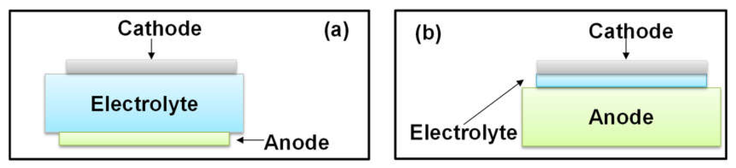
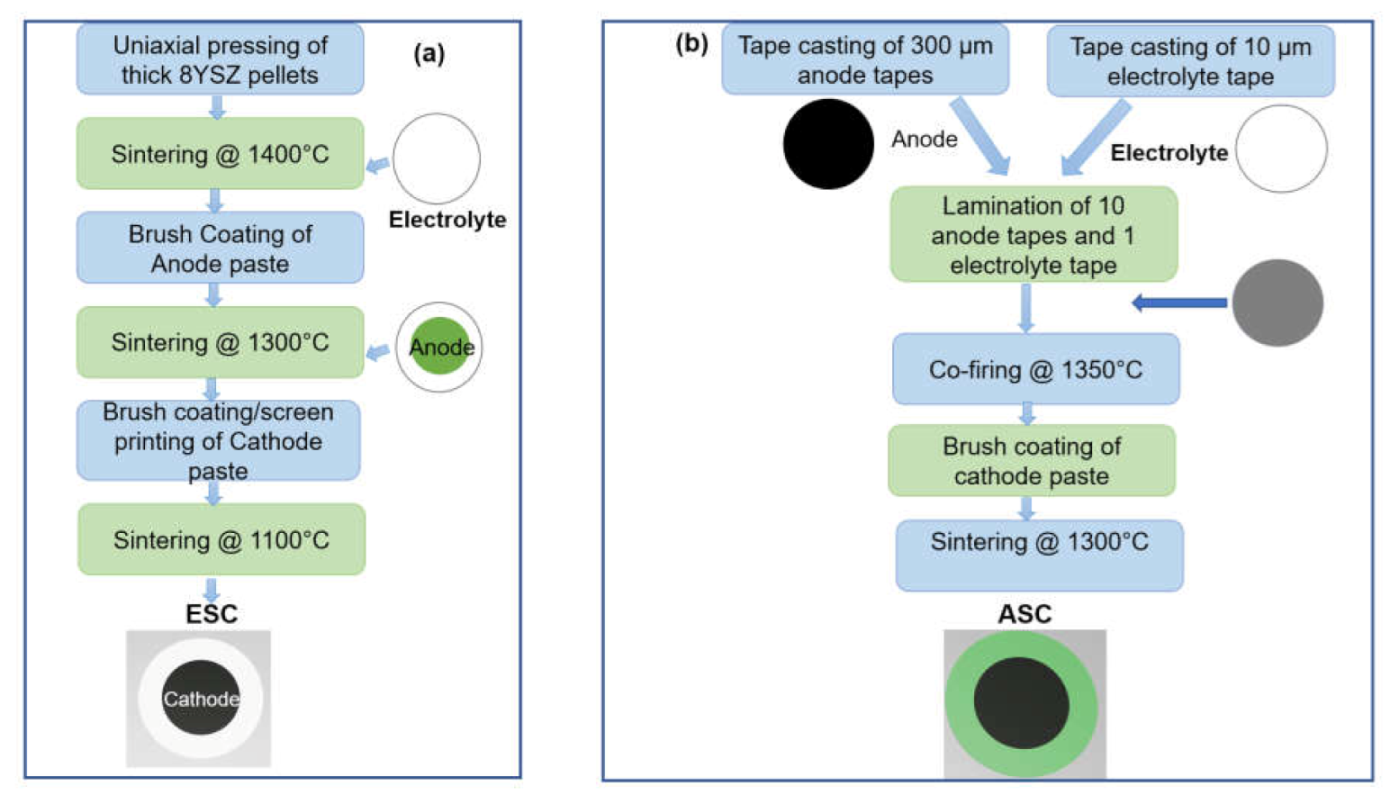
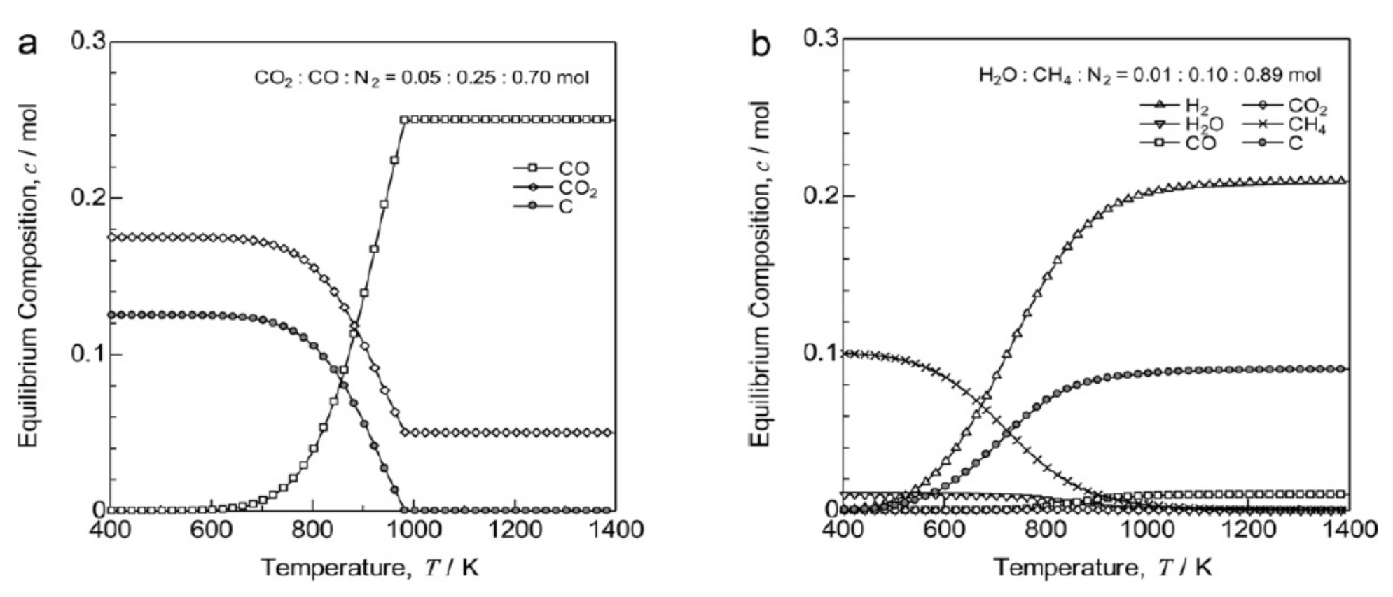
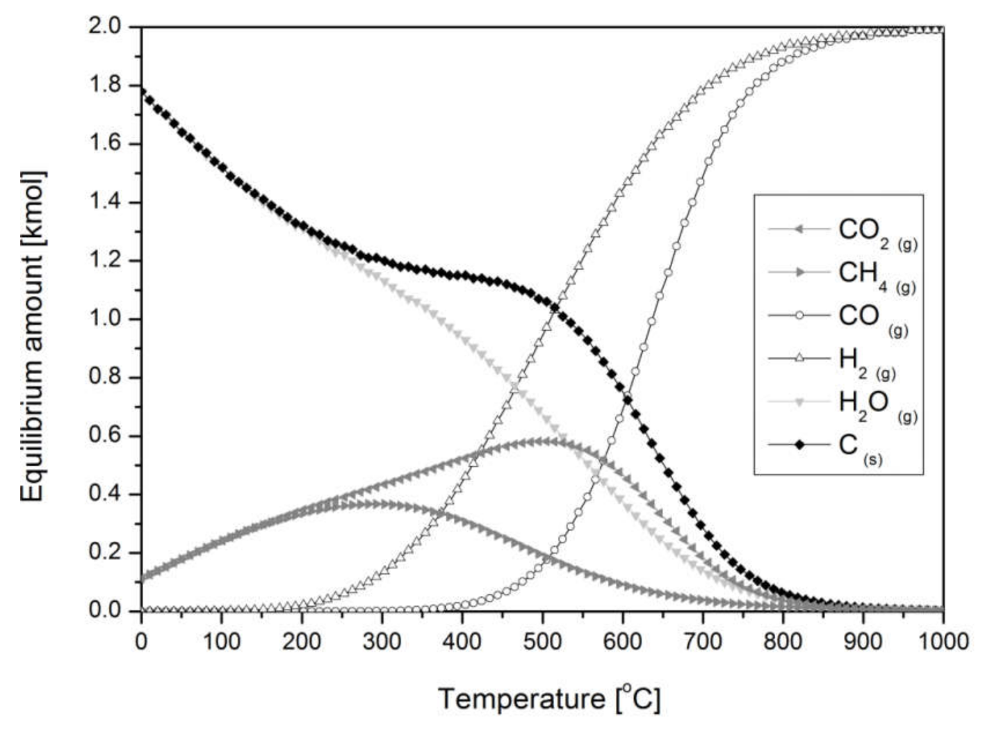
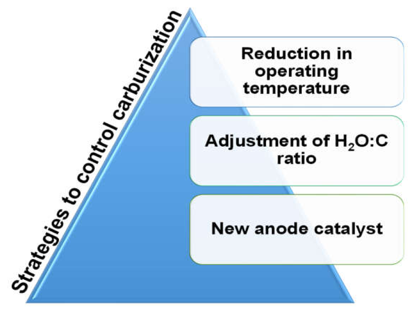
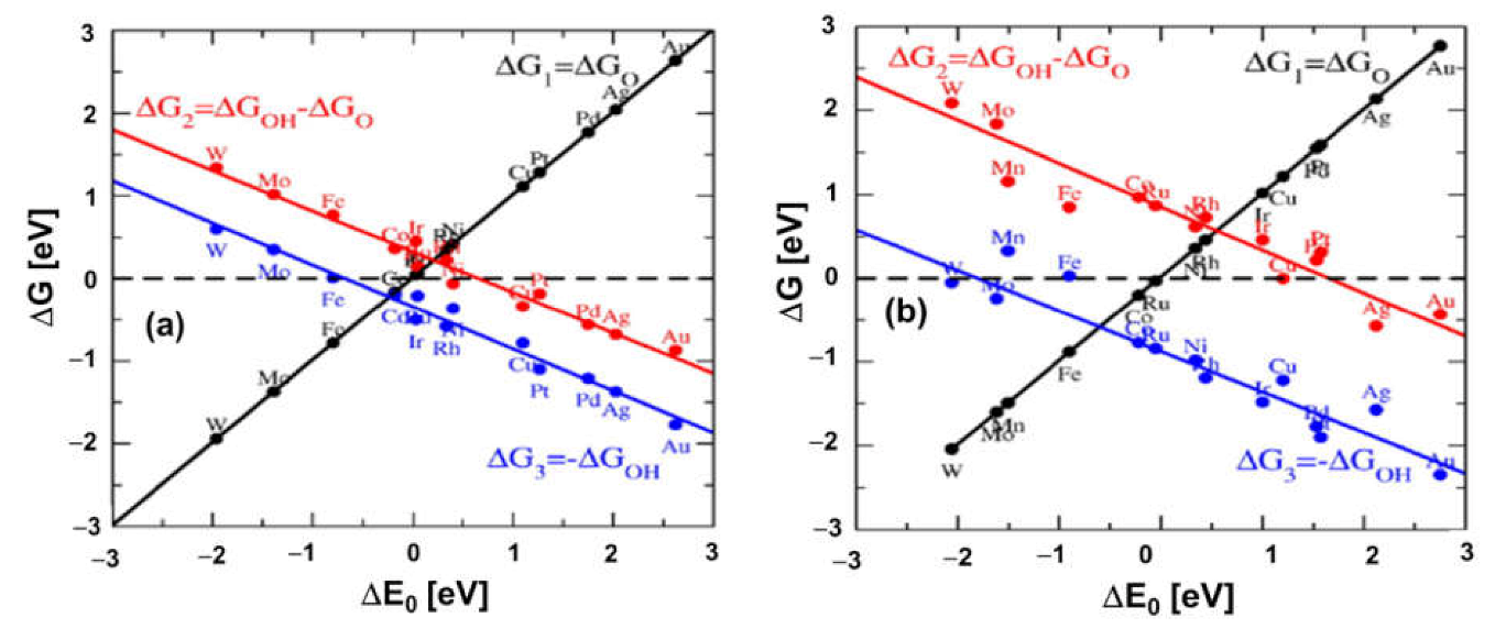
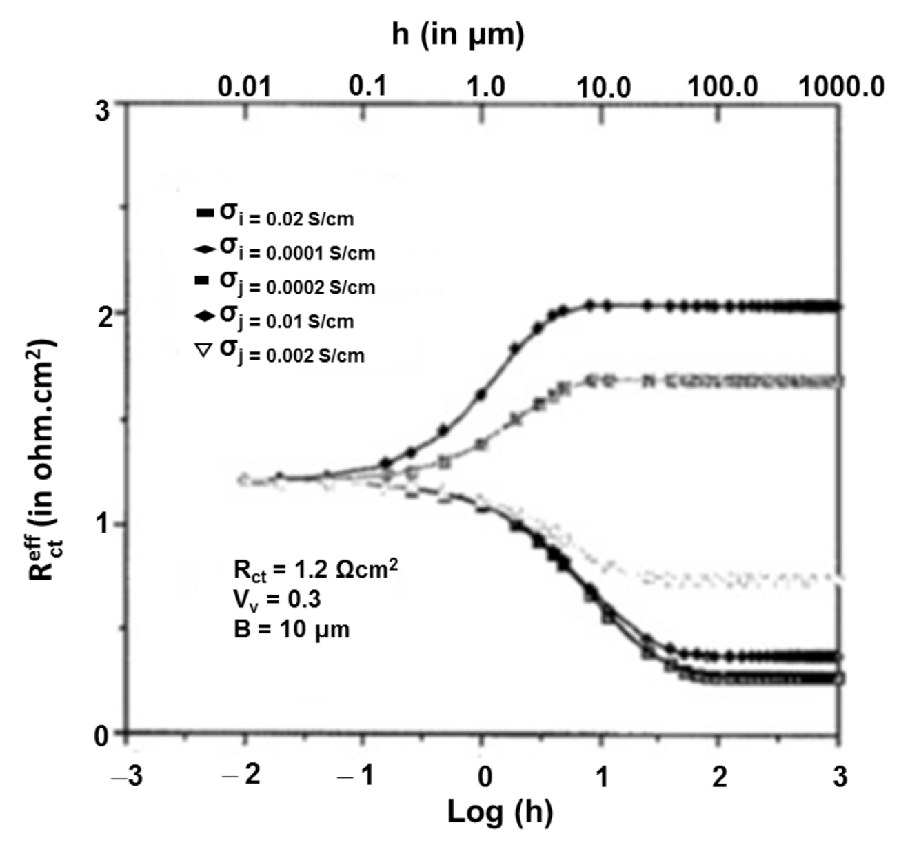
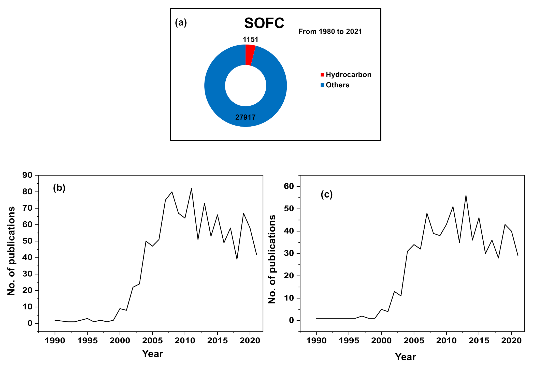
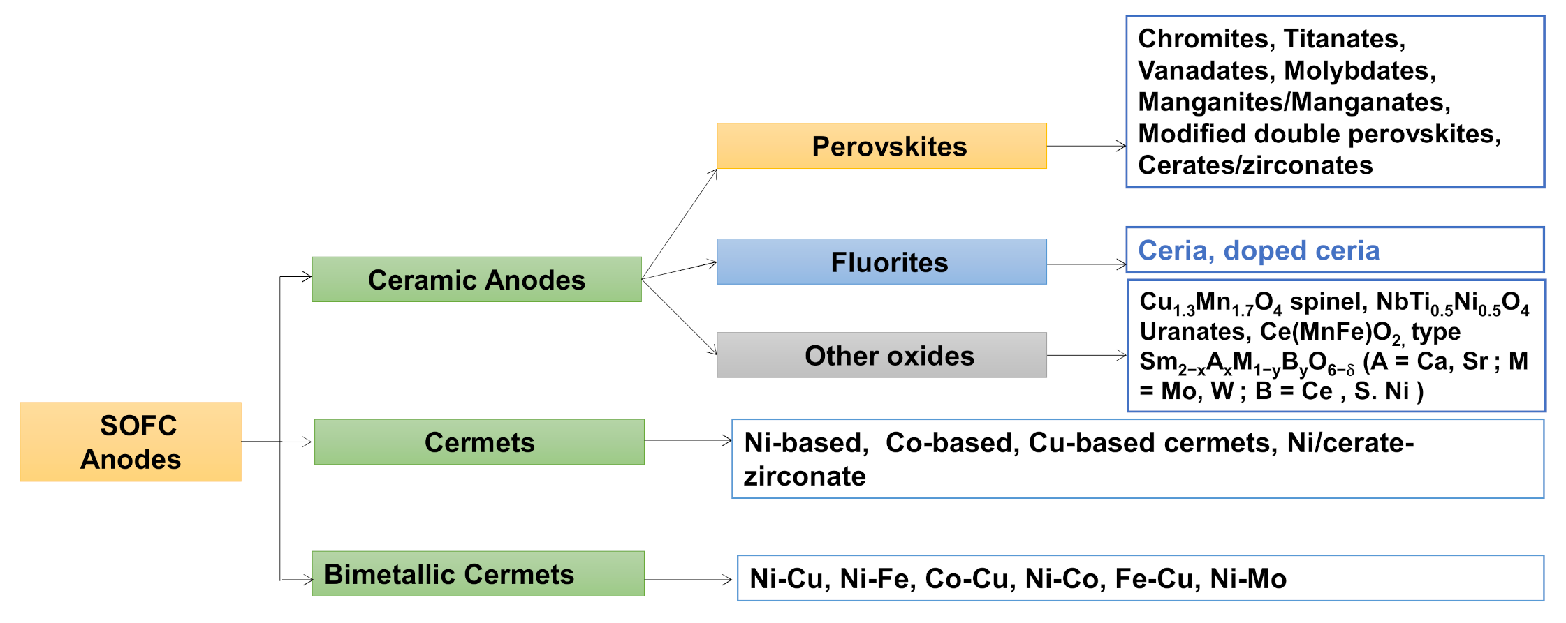
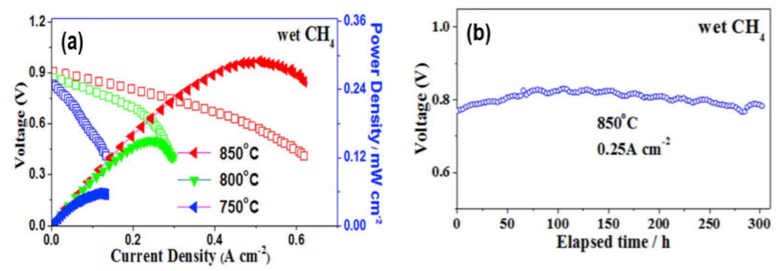
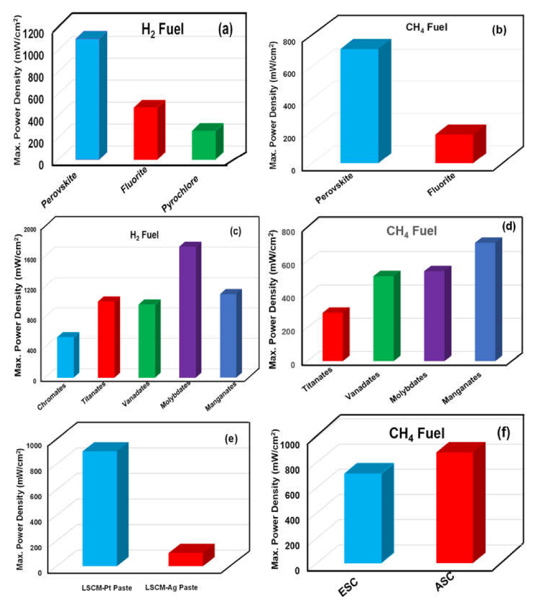
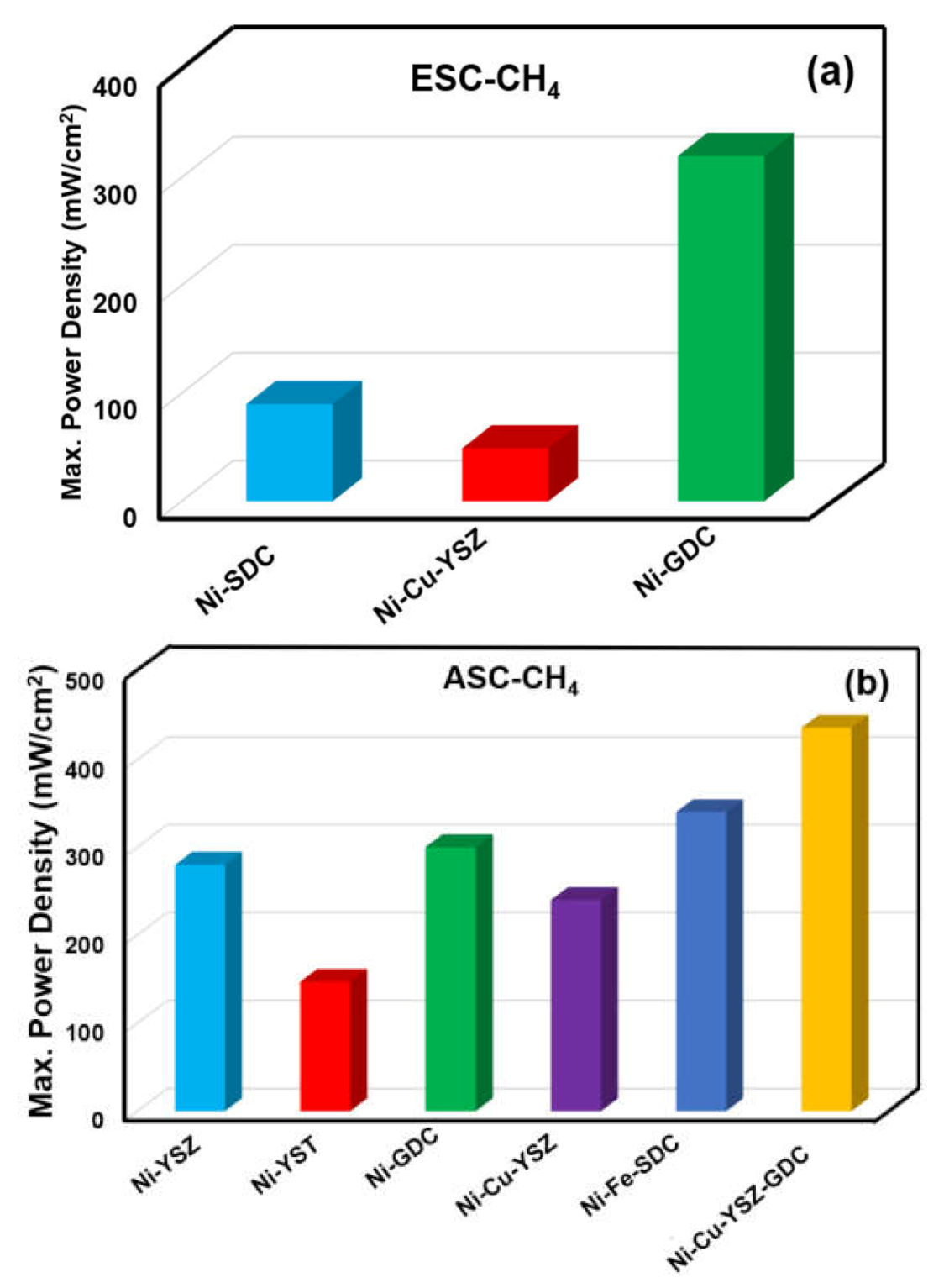
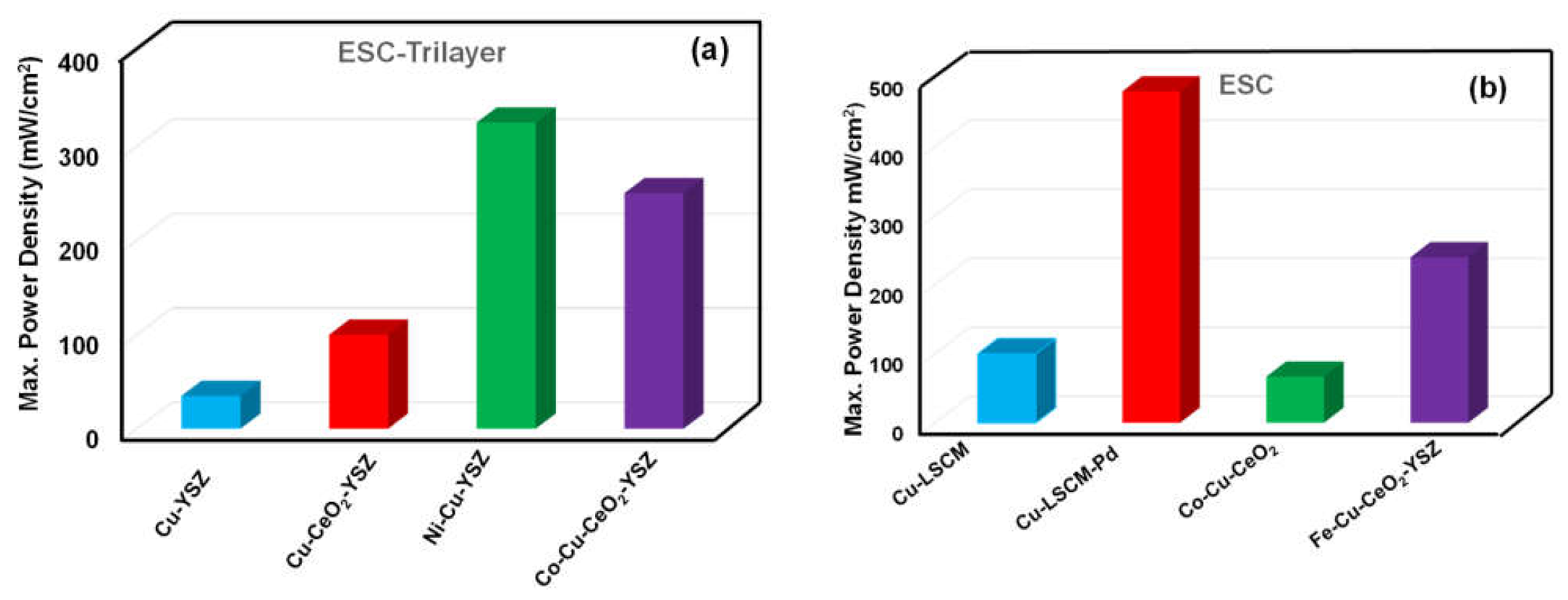
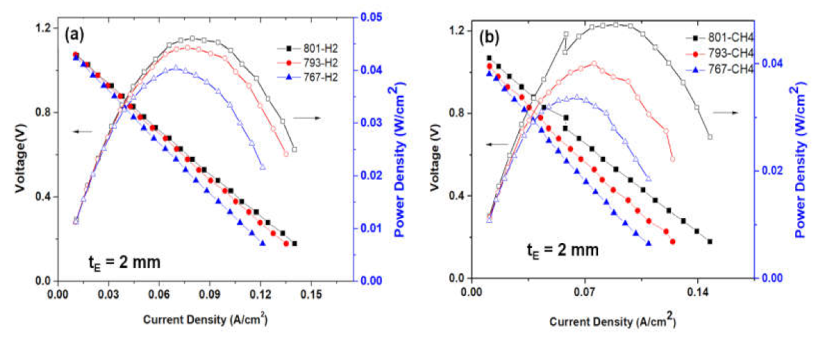
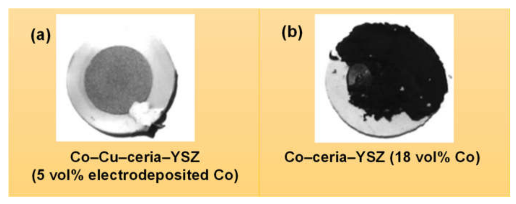
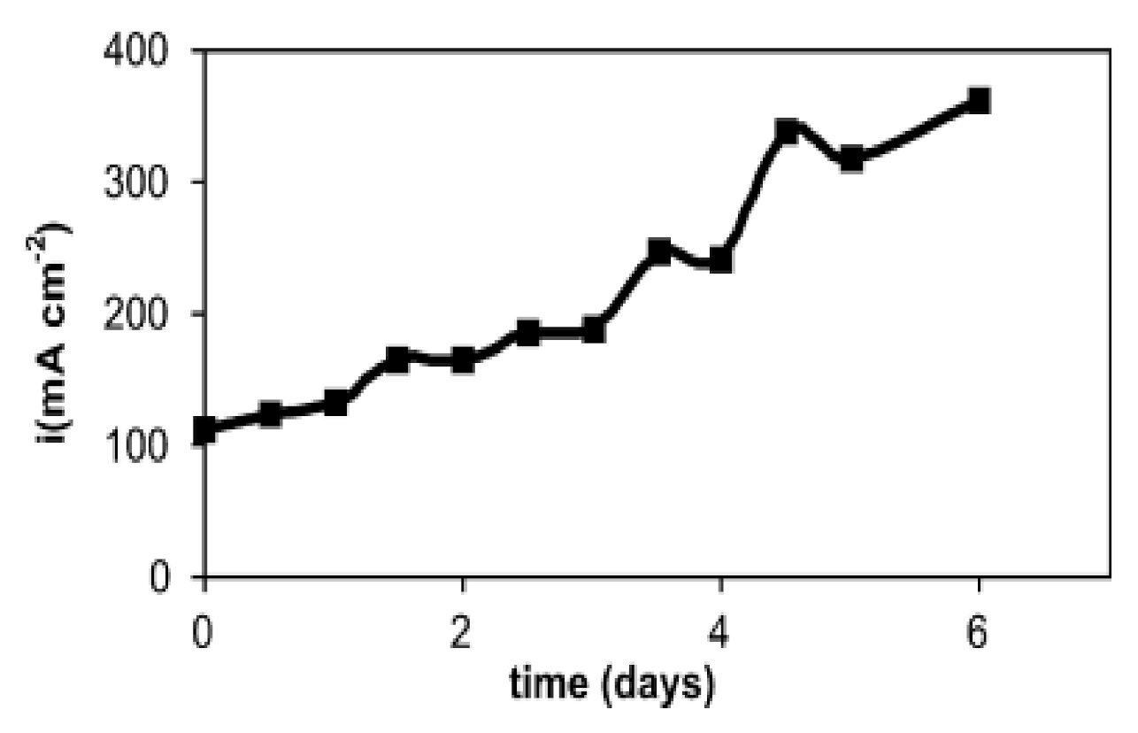
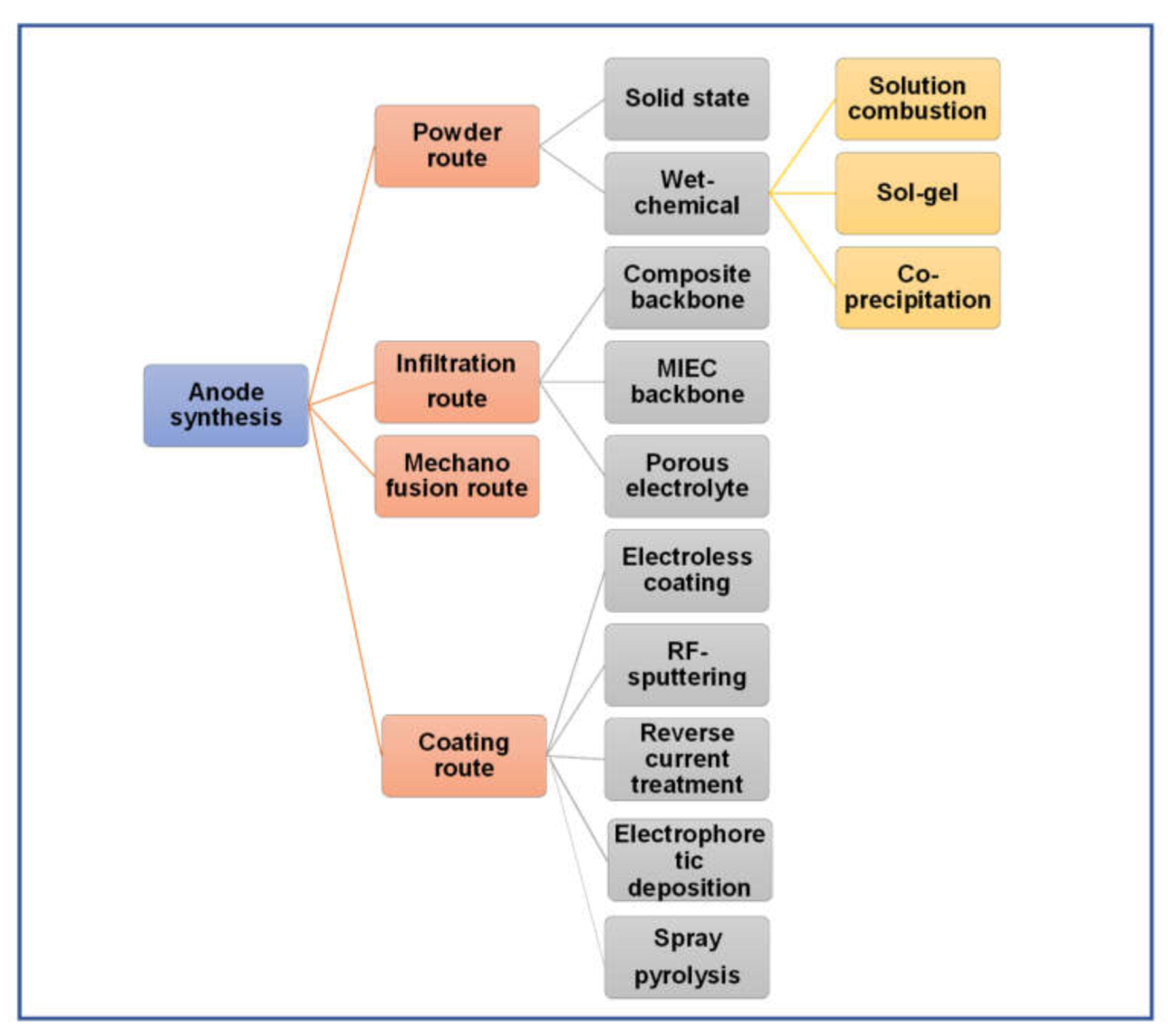
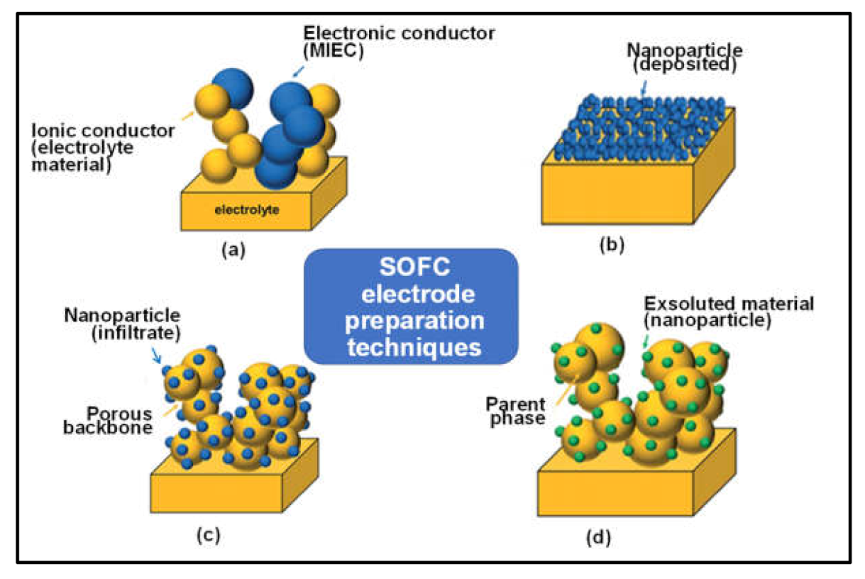
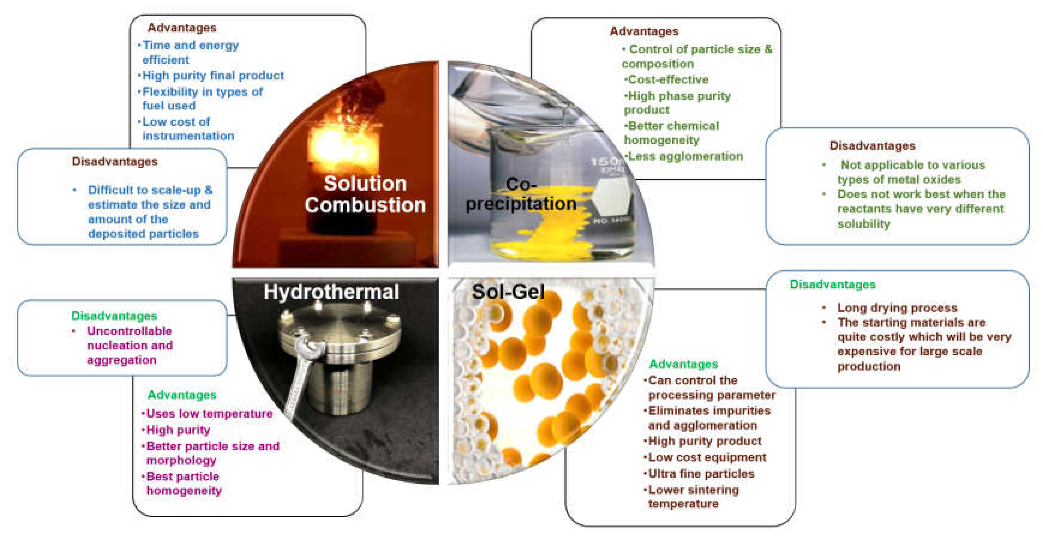
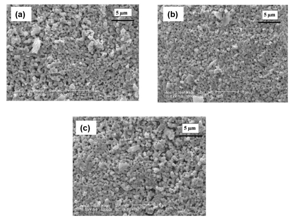
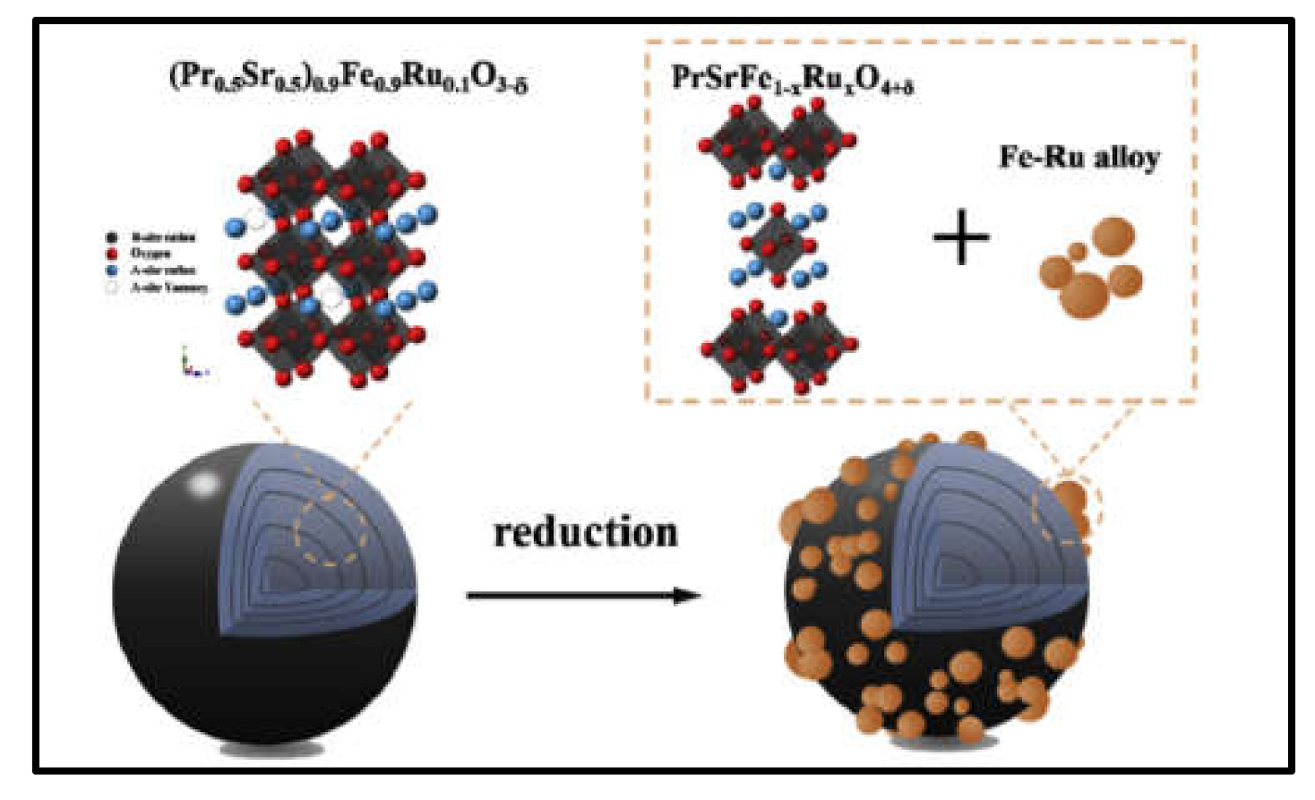
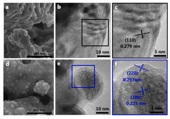
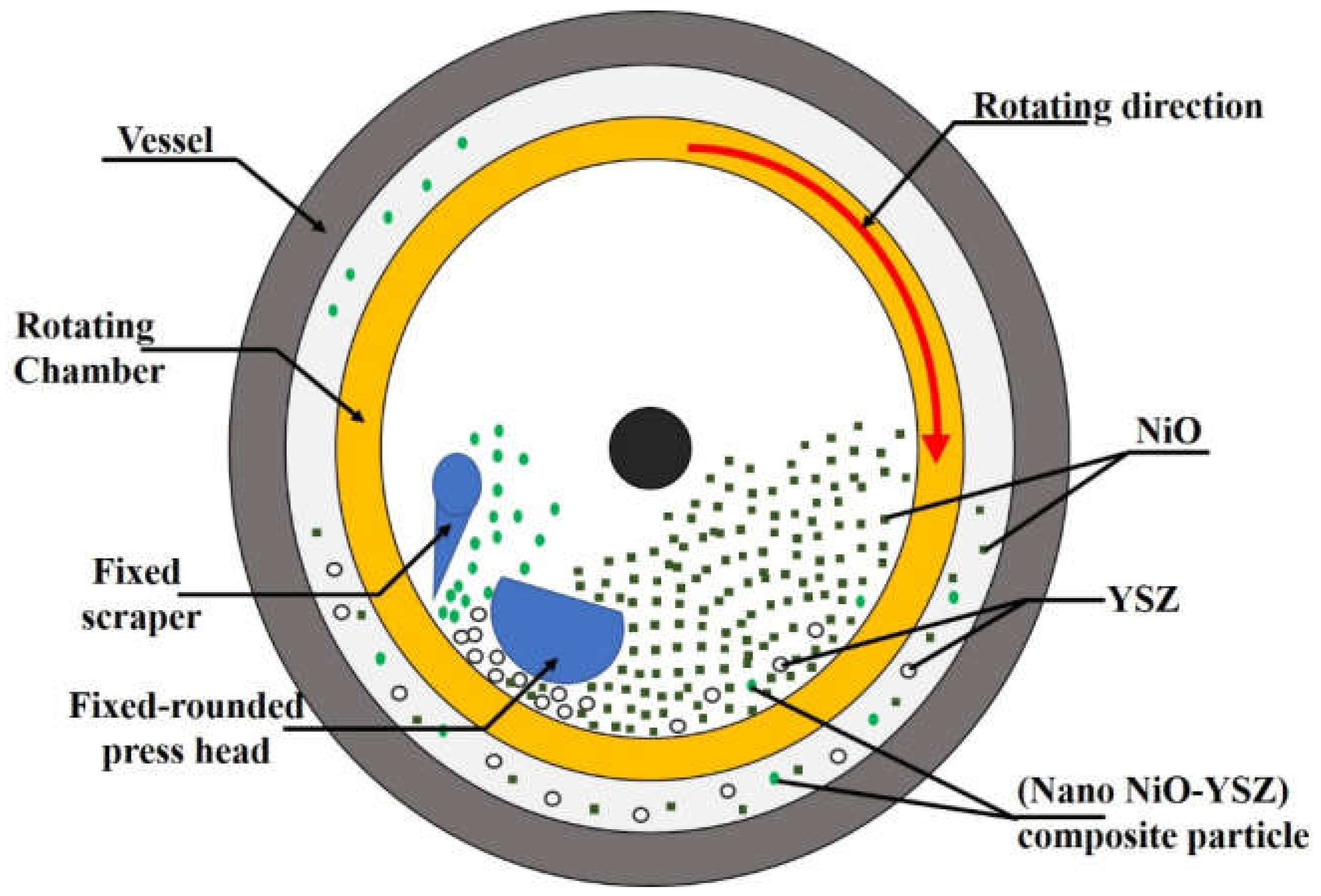
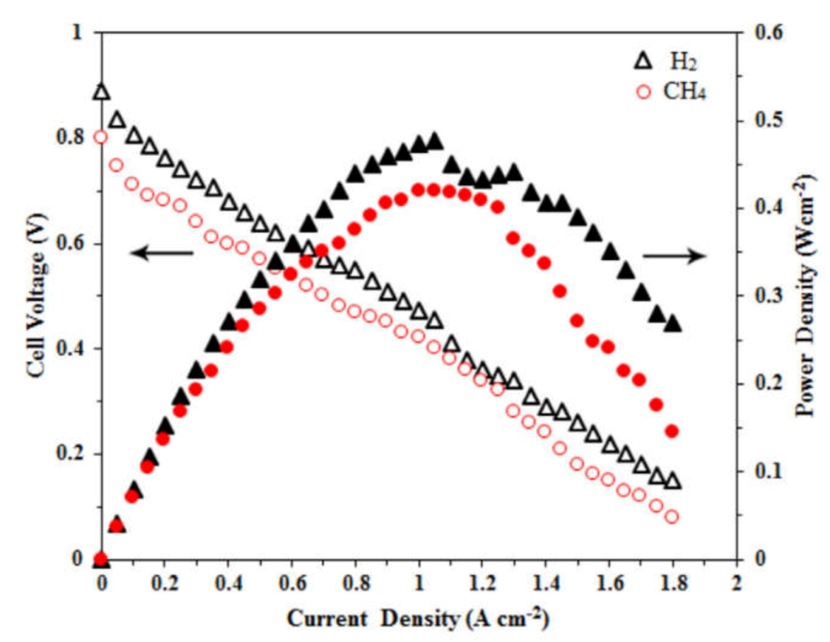
Figure 1. Schematic of most popular SOFC planar configurations: (a) ESC and (b) ASC.
Suschem 02 00039 g001
Figure 2. Flowchart depicting the steps involved in the fabrication of (a) ESC and (b) ASC.
Suschem 02 00039 g002
Figure 3. The equilibrium concentration of product for a typical SOFC feed composition (a) CO2:CO:N2 = 0.05:0.25:0.70 and (b) H2O:CH4:N2 = 0.01:0.10:0.89 mol (adapted from [25]).
Suschem 02 00039 g003
Figure 4. Equilibrium amounts for gaseous components and coke in the dry reforming of methane process (CH4/CO2/Ar = 1/1/8, p = 1 bar) (adapted from [26]).
Suschem 02 00039 g004
Figure 5. Strategies to control carburization.
Suschem 02 00039 g005
Figure 6. Gibbs free energy for the individual elementary reactions of the anode for different metal catalysts. (a) Values for surface terraces and (b) for surface steps. The black, red, and blue lines correspond to the change in free energy for the Equations (6)–(8), respectively (adapted from [36]).
Suschem 02 00039 g006
Figure 7. Correlation between effective charge transfer resistance and electrode thickness of different ionic conductivity (adapted from ref. [42]).
Suschem 02 00039 g007
Figure 8. Scopus database analysis using keywords (a) SOFC, (b) SOFC+ HC, and (c) SOFC +HC+anode (data were acquired on 13 October 2021).
Suschem 02 00039 g008
Figure 9. Flowchart showing the classification of HC-compatible SOFC anodes.
Suschem 02 00039 g009
Figure 10. (a) Voltage–current curves and (b) stability test for the SFCM/LSGM/LSCF SOFC in wet CH4 (adapted from [131]).
Suschem 02 00039 g010
Figure 11. Performance of oxide anodes with the different crystal structure (a) in H2 and (b) CH4; with different composition in (c) in H2 and (d) CH4; LSCM (e) with different current collector pastes and (f) different configurations.
Suschem 02 00039 g011
Figure 12. Performance of Ni cermet anodes in (a) ESC and (b) ASC operated with CH4.
Suschem 02 00039 g012
Figure 13. Bar graph showing the maximum power density of SOFCs fabricated from Cu-cermet anodes (a) using single, bi-layer, and tri-layer infiltration and (b) in ESC configuration.
Suschem 02 00039 g013
Figure 14. Performance of 2 mm electrolyte-supported SOFC with Ni0.90Cu0.10YSZ0.95GDC0.05 anode in (a) H2 fuel and (b) CH4 fuel at ■ 801 °C, ● 793 °K, and ▲ 767 °C; filled shapes correspond to the V–I curve (adapted from [96]).
Suschem 02 00039 g014
Figure 15. Photograph of the cells (a) after reduction in dry H2 at 800 °C and (b) exposure to dry CH4 for 3 h at 800 °C (adapted from [220]).
Suschem 02 00039 g015
Figure 16. The plot of current density vs. time of a SOFC with Co-YSZ anode with 10% (v/v) H2S/CH4 at 0.5 V and 850 °C (adapted from [263]).
Suschem 02 00039 g016
Figure 17. Flowchart showing various routes used for anode synthesis.
Suschem 02 00039 g017
Figure 18. Schematic of various methods adopted for the fabrication of composite electrode using (a) the conventional ceramic processing method, (b) thin-film deposition, (c) infiltration, and (d) ex-solution (adapted from [281]).
Suschem 02 00039 g018
Figure 19. Schematic showing the advantages and disadvantages of the most widely used wet-chemical routes.
Suschem 02 00039 g019
Figure 20. Scanning electron micrographs of Ni-CGO cermet catalysts (a) after reduction and after catalytic tests at (b) S/C = 0.5 and (c) S/C = 1.5 at 800 °C for 5 h (adapted from [282]).
Suschem 02 00039 g020
Figure 21. Schematic diagram of the morphology and crystal structure evolution of PePSFeRu after reduction (adapted from [300]).
Suschem 02 00039 g021
Figure 22. (a) SEM and (b,c) TEM images of as-prepared PSFRN. (d) SEM and (e,f) TEM images of R-PSFRN (adapted from ref. [303]).
Suschem 02 00039 g022
Figure 23. Schematic of the mechanofusion system (redrawn after [321]).
Suschem 02 00039 g023
Figure 24. Cell voltage and power density curves of the SOFC at 800 °C in H2 and CH4 fuels (adapted from [303]).
Suschem 02 00039 g024
Table 1. Different reactions of HCs occurring at the operating conditions of SOFC along with their advantages and limitations.
Types of
Reactions
Reactions InvolvedTemp.
Range (°C)
AdvantagesLimitations
Steam Reforming CH   4 +   H 2 O   CO   +   3 H 2 (syngas) (endothermic)
CO   +   H 2 O     CO 2   +   H 2
(exothermic)
700Suitable for external reformersReforming fuel inside SOFC anode (internal steam reforming) will affect the performance; more steam results in low OCV in SOFC due to fuel dilution
Autothermal Reforming (ATR) 2 CH 4 +   O 2   +   CO 2     3 H 2   +   3 CO   +   H 2 O
(exothermic)
4 CH 4 +   O 2   +   2 H 2 O   10 H 2   +   4 CO
950–1060Reactor is compact in designReaction pressure is in the range 30–50 bar
Partial Oxidation (POX)Thermal partial oxidation (TPOX)
C n H m   +   2 n + m 4   O 2     n   CO   +   m 2   H 2 O
(exothermic)
Catalytic partial oxidation (CPOX)
C n H m   +   m 2 + n   O 2     n   CO   +   m 2   H 2 O (with catalyst)
1200CPOX reaction utilizes a catalyst to reduce the reaction temperature to around 800–900 °CCPOX is suitable only for low sulfur (<50 ppm) fuel as catalysts are much more prone to sulfur poisoning.CPOX has seldom been used in SOFC anodes, as the pO2 in the chamber must be sustained <10−18 atm to trigger SOFC operation
Direct Methane (DM) Oxidation CH 4 +   2 O 2     CO 2   +   2 H 2 O >750DM-SOFCs possess maximum catalytic activity for complete oxidation of methaneOxidation of Ni
Table 2. Long-term stability data of SOFCs with hydrocarbon compatible anodes.
AnodeElectrolyteCathodeFuelTemp. °CPower Density (Wcm−2)StabilityRef.
(PrBa)0.95(Fe0.9Nb0.1)2O5+δ oxideLSGMPrBaCo2O5+δH2
wet CH4
dry CH4
8001.05
0.64
0.57
Highly coking resistant in dry CH4 for 200 h[229]
MgO-modified Ni–SDCLSGMSCCO-SDCHumidified CH48000.714Excellent long-term stability for 330 h[230]
Ni–SDCSDCSSC-SDCLiquid methanol6500.698No degradation during 60 h long-term testing[231]
Li-modified Ni–SDC
Na-modified Ni–SDC
LSGMSCCO-SDCWet CH48000.212
0.231
Stability
up to 70 h
[232]
MoO2-based anodeYSZLSMn-dodecane850Initially 0.34; after optimizing porosity of anode = 2.5Highly coke resistant with improved long-term stability[233]
Ni–GDC with 0.5 wt% Sn catalystGDCLSCF-GDCDry CH46500.93Operates for over 40 h without degradation[234]
MoO2 porous thin film deposited on Ni–YSZYSZLSMMixture of n-dodecane and air750>4.024 h
Highly coking resistant
[235]
Ni-Fe-LSGMLSGMSSCCH48000.48Good stability as no coke deposition after 15 h[236]
Ni-infiltrated porous GDC scaffoldsGDCLSCFWet CH46000.125Stable operation for 24 h[237]
Layered PrBaMn2O5+δ anode with PrBaMn2O5+δ and Co–Fe catalystLSGMNdBa0.5Sr0.5 Co1.5 Fe0.5 O5+δ–Ce0.9 Gd0.1 O2−δ (NBSCF50-GDC)C3H87001.32Long-term stability tested for 500 h[140]
Ni–YSZYSZLSM-YSZ
Table 3. The ASR and power densities of SOFCs fabricated from hydrocarbon compatible anodes.
AnodeConfigurationASR
(Ωcm2)
Temp.
(°C)
FuelPower Density mW cm−2Ref.
Ni/Ag/GDCYSZ/LSCF-GDC1.12750Syngas33 [271]
La0.20Sr0.25Ca0.45TiO3 decorated with CGO coating and nanoparticles of Ni, Pt, or Rh.6ScSZ/LSM-YSZ0.78850 Syngas + 8 ppm H2S-[272]
Ni/10Sc1CeSZ10Sc1CeSZ symmetrical cell24.3800CH4-[273]
La0.65 Ce0.1Sr0.25Cr0.5 Mn0.5O3−δESC-YSZ1.6900CH4-[274]
Ni- Ce0.9Sr0.1 Cr0.5V0.5 O3-YSZESC-YSZ5.9850H2S-CH425[251]
La0.8 Sr0.2ScxMn1−xO3–GDC-PdThree-layer ESC infiltration0.4700CH4341[139]
La0.75Sr0.25Cr0.5Mn0.5O3−δ ESC-YSZ-symmetrical cell0.613950CH4347[74]
LSCM-0.5%Pd-5%CeO2Three-layer ESC infiltration0.14800CH4710[275]
La0.75Sr0.25Cr0.5Mn0.5 O3−δESC2.3800Ethanol101[72]
(La0.75Sr0.25)Cr0.5 Mn0.5 O3−δESC-YSZ-Symmetric0.3900CH4230[73]
La0.8Sr0.2ScxMn1−xO3–GDC-PdThree-layer ES infiltration0.4700CH4341[163]
Sr0.6La0.4TiO3-50% CeO2ESYSZ2900CH4139.6[276]
La0.2Sr0.7TiO3-GDC-CuThree-layer ESC infiltration0.15750CH4540[100]
10%Ni-LSFCES-CGO0.33800Propane421[277]
(Pr0.75Sr0.25)1−xCr0.5 Mn0.5O3−δES-YSZ3.52910CH418[278]
1:1 Co-Cu-CeO2ESC-YSZ3.72800CH467[279]
50:50 CoCu-CeO2-YSZ3-layer-YSZ0.8800CH4250[221]
Cu1.3Mn1.7O4 on Ni–SDCASC-SDC0.120700CH4375[280]
Publisher’s Note: MDPI stays neutral with regard to jurisdictional claims in published maps and institutional affiliations.

