

Evaluation of Rotational Stability and Stress Shielding of a Stem Optimized for Hip Replacements—A Finite Element Study


Abstract
:1. Introduction
1.1. Rotational Instability
- F2= force transmitted to the bone;
- L2=lever arm of F2.
1.2. Stress Shielding
2. Materials and Methods
2.1. Evaluation of Stem Stiffness
2.2. Bone Implant Stress Assessment
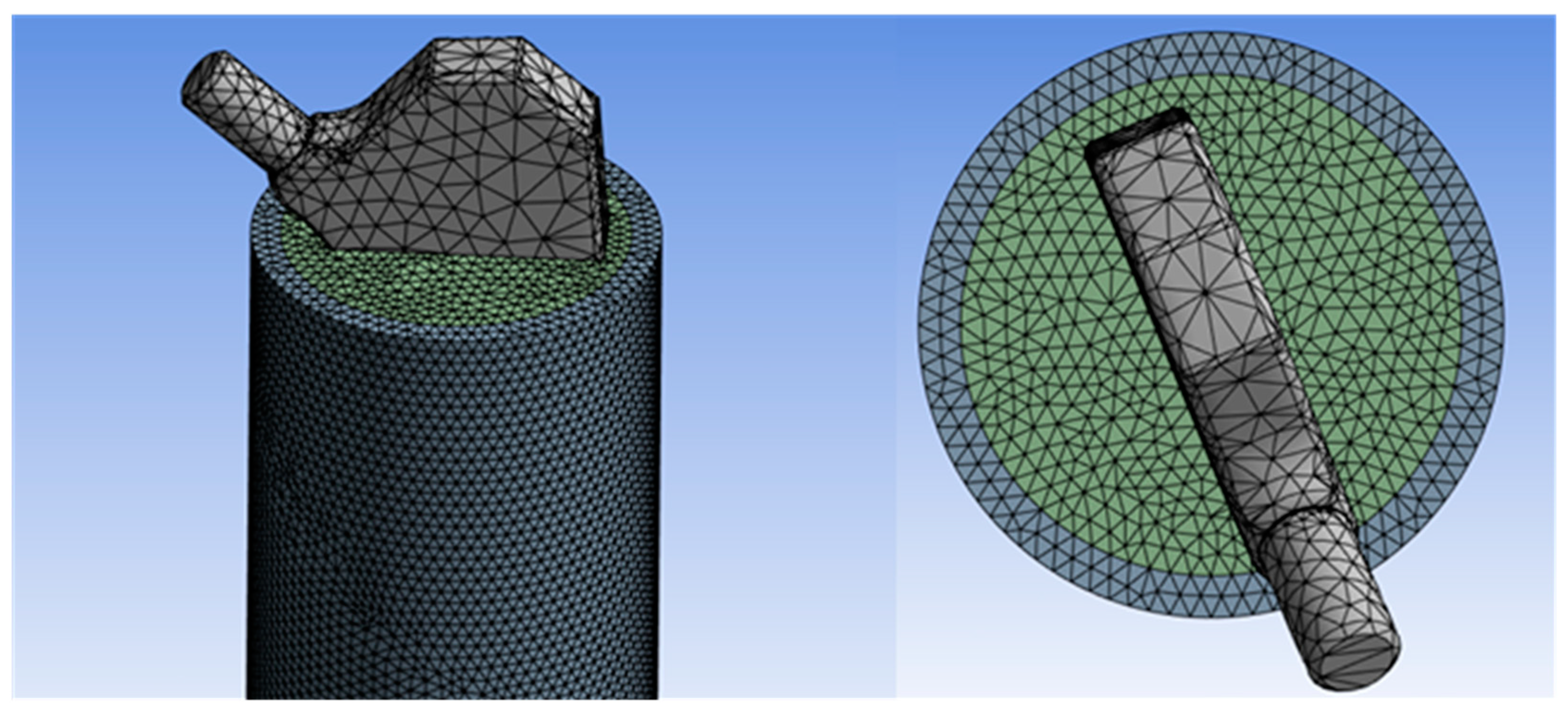
2.3. Meshing
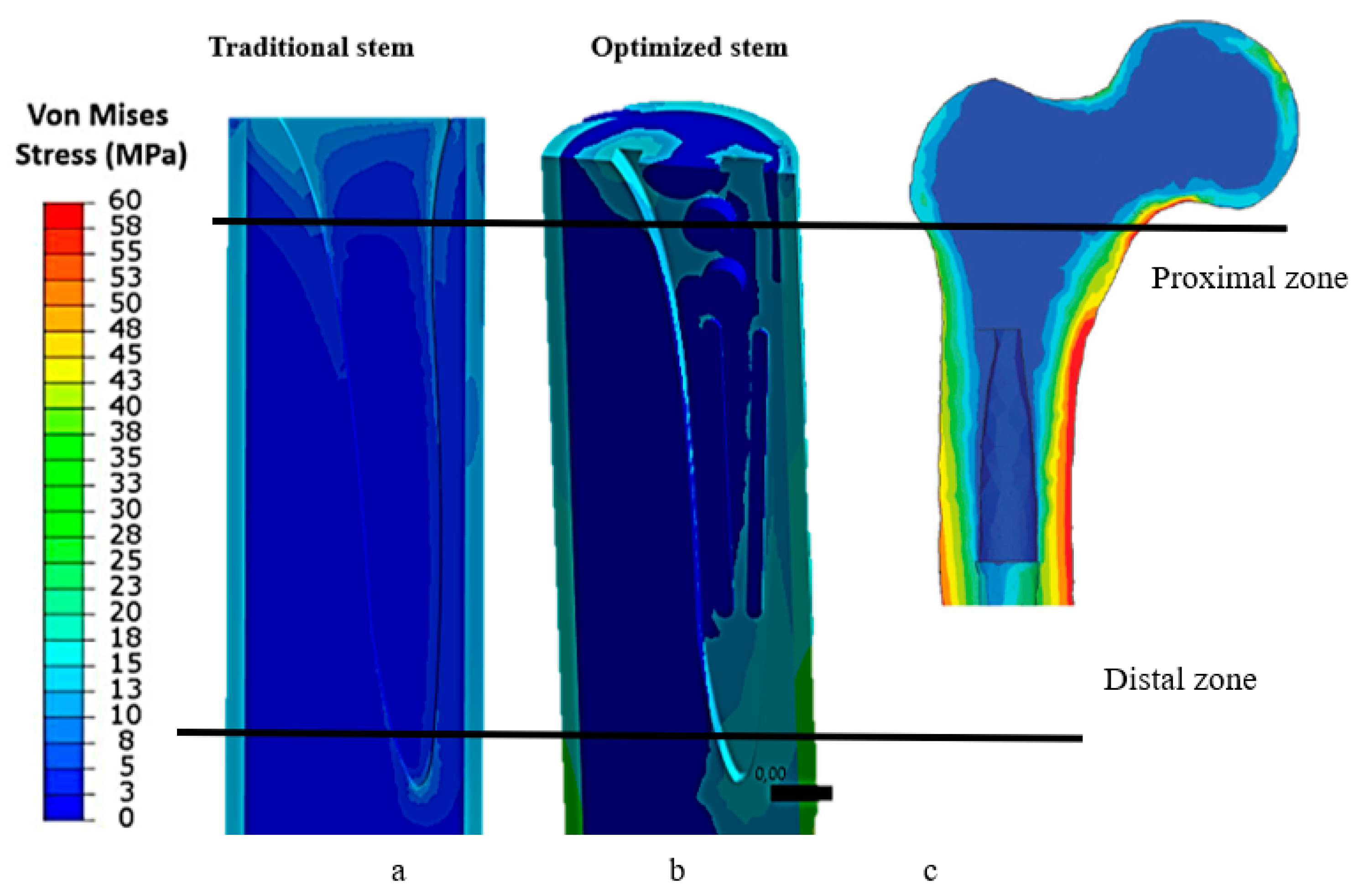
3. Results
4. Discussion
4.1. Effect of Stem Stiffness
4.2. Optimization of Stem–Femur Contact
5. Conclusions
Author Contributions
Funding
Institutional Review Board Statement
Informed Consent Statement
Data Availability Statement
Conflicts of Interest
References
- Yang, S.; Liu, Y.; Ma, S.; Ding, C.; Kong, Z.; Li, H.; Huang, F.; Chen, H.; Zhong, H. Stress and strain changes of the anterior cruciate ligament at different knee flexion angles: A three-dimensional finite element study. J. Orthop. Sci. 2023; in press. [Google Scholar] [CrossRef]
- Rani, S.; Jain, N.; Barua, S.L.; Idnani, S.; Kaushik, N. Stress analysis in implant, abutment, and peripheral bone with different restorative crown and abutment materials: A three-dimensional finite element analysis study. Dent. Res. J. 2023, 20, 62. [Google Scholar] [CrossRef]
- Wei, W.; Wang, T.; Liu, J.; Mao, K.; Pan, C.; Li, H.; Zhao, Y. Biomechanical effect of proximal multifidus injury on adjacent segments during posterior lumbar interbody fusion: A finite element study. BMC Musculoskelet Disord. 2023, 24, 521. [Google Scholar] [CrossRef] [PubMed]
- Kovuru, V.; Aileni, K.R.; Mallepally, J.P.; Kumar, K.S.; Sursala, S.; Pramod, V. Factorial analysis of variables affecting bone stress adjacent to mini-implants used for molar distalization by direct anchorage-A finite element study. J. Orthod. Sci. 2023, 12, 18. [Google Scholar]
- Rometsch, E.; Bos, P.K.; Koes, B.W. Survival of short hip stems with a “modern”, trochanter-sparing design—A systematic literature review. Hip Int. 2012, 22, 344–354. [Google Scholar] [CrossRef]
- Banerjee, S.; Pivec, R.; Issa, K.; Harwin, S.F.; Mont, M.A.; Khanuja, H.S. Outcomes of short stems in total hip arthroplasty. Orthopedics 2013, 36, 700–707. [Google Scholar] [CrossRef]
- Moskal, J.T.; Capps, S.G. Is limited incision better than standard total hip arthroplasty? A meta-analysis. Clin. Orthop. Relat. Res. 2013, 471, 1283–1294. [Google Scholar] [CrossRef] [PubMed] [Green Version]
- Berstock, J.R.; Blom, A.W.; Beswick, A.D. A systematic review and meta-analysis of the standard versus miniincision posterior approach to total hip arthroplasty. J. Arthroplast. 2014, 29, 1970–1982. [Google Scholar] [CrossRef] [PubMed]
- Yue, C.; Kang, P.; Pei, F. Comparison of direct anterior and lateral approaches in total hip arthroplasty: A systematic review and meta-analysis (PRISMA). Medicine 2015, 94, e2126. [Google Scholar] [CrossRef]
- Feyen, H.; Shimmin, A.J. Is the length of the femoral component important in primary total hip replacement? Bone Jt. J. 2014, 96, 442–448. [Google Scholar] [CrossRef]
- Khanuja, H.S.; Banerjee, S.; Jain, D.; Pivec, R.; Mont, M.A. Short bone-conserving stems in cementless hip arthroplasty. J. Bone Jt. Surg. Am. 2014, 96, 1742–1752. [Google Scholar]
- Courpied, J.P.; Caton, J.H. Total hip arthroplasty, state ofthe art for the 21st century. Int. Orthop. 2011, 35, 149–150. [Google Scholar] [CrossRef] [Green Version]
- Khanuja, H.S.; Vakil, J.J.; Goddard, M.S.; Mont, M.A. Cementless femoral fixation in total hip arthroplasty. J. Bone Jt. Surg. Am. 2011, 93, 500–509. [Google Scholar] [CrossRef] [PubMed]
- Brown, T.E.; Larson, B.; Shen, F.; Moskal, J.T. Thigh pain after cementless total hip arthroplasty: Evaluation and management. J. Am. Acad. Orthop. Surg. 2002, 10, 385–392. [Google Scholar] [CrossRef] [PubMed] [Green Version]
- Engh, C.A., Jr.; Young, A.M.; Engh, C.A., Sr.; Hopper, R.H., Jr. Clinical consequences of stress shielding after porous-coated total hip arthroplasty. Clin. Orthop. Relat. Res. 2003, 417, 157–163. [Google Scholar] [CrossRef]
- Lakstein, D.; Eliaz, N.; Levi, O.; Backstein, D.; Kosashvili, Y.; Safir, O.; Gross, A.E. Fracture of cementless femoral stems at the mid-stem junction in modular revision hip arthroplasty systems. J. Bone Jt. Surg. Am. 2011, 93, 57–65. [Google Scholar] [CrossRef] [PubMed] [Green Version]
- Wilson, D.A.; Dunbar, M.J.; Amirault, J.D.; Farhat, Z. Early failure of a modular femoral neck total hip arthroplasty component: A case report. J Bone Jt. Surg. Am. 2010, 92, 1514–1517. [Google Scholar] [CrossRef]
- Quintana, J.M.; Arostegui, I.; Azkarate, J.; Goenaga, J.I.; Elexpe, X.; Letona, J.; Arcelay, A. Evaluation of explicit criteria for total hip joint replacement. J. Clin. Epidemiol. 2000, 53, 1200–1208. [Google Scholar] [CrossRef]
- Gademan, M.G.J.; Hofstede, S.N.; Vlieland, T.P.M.V.; Nelissen, R.G.H.H.; De Mheen, P.J.M.-V. Indication criteria for total hip or knee arthroplasty in osteoarthritis: A state-of-the-science overview. BMC Musculoskelet. Disord. 2016, 17, 463. [Google Scholar] [CrossRef] [Green Version]
- Lucchini, S.; Castagnini, F.; Giardina, F.; Tentoni, F.; Masetti, C.; Tassinari, E.; Bordini, B.; Traina, F. Cementless ceramic-on ceramic total hip arthroplasty in post-traumatic osteoarthritis after acetabular fracture: Long-term results. Arch. Orthop. Trauma. Surg. 2021, 141, 683–691. [Google Scholar] [CrossRef]
- Fokter, S.K.; Levašič, V.; Kovač, S. The Innovation Trap: Modular Neck in Total Hip Arthroplasty. ZdravVestn 2017, 86, 115–126. [Google Scholar]
- Aljenaei, F.; Catelas, I.; Louati, H.; Beaulé, P.E.; Nganbe, M. Effects of hip implant modular neck material and assembly method on fatigue life and distraction force. J. Orthop. Res. 2017, 35, 2023–2030. [Google Scholar] [CrossRef]
- Zajc, J.; Moličnik, A.; Fokter, S.K. Dual Modular Titanium Alloy Femoral Stem Failure Mechanisms and Suggested Clinical Approaches. Materials 2021, 14, 3078. [Google Scholar] [CrossRef]
- Weiser, M.C.; Chen, D.D. Revision for taper corrosion at the neck-body junction following total hip arthroplasty: Pearls and pitfalls. Curr. Rev. Musculoskelet. Med. 2016, 9, 75–83. [Google Scholar] [CrossRef] [Green Version]
- Wright, C.G.; Sporer, S.; Urban, R.; Jacobs, J. Fracture of a Modular Femoral Neck After Total Hip Arthroplasty: A Case Report. J. Bone Jt. Surg. 2010, 92, 1518–1521. [Google Scholar]
- Vucajnik, I.; Fokter, S.K. Modular Femoral Neck Fracture After Total Hip Arthroplasty. In Recent Advances in Hip and Knee Arthroplasty; IntechOpen: London, UK, 2012. [Google Scholar]
- Grupp, T.M.; Weik, T.; Bloemer, W.; Knaebel, H.-P. Modular titanium alloy neck adapter failures in hip replacement—Failure mode analysis and influence of implant material. BMC Musculoskelet. Disord. 2010, 11, 3. [Google Scholar] [CrossRef] [Green Version]
- Meftah, M.; Haleem, A.M.; Burn, M.B.; Smith, K.M.; Incavo, S.J. Early Corrosion-Related Failure of the Rejuvenate Modular Total Hip Replacement. J. Bone Jt. Surg. Am. 2014, 96, 481–487. [Google Scholar] [CrossRef] [Green Version]
- Bernstein, D.T.; Meftah, M.; Paranilam, J.; Incavo, S.J. Eighty-six Percent Failure Rate of a Modular-Neck Femoral Stem Design at 3 to 5 Years: Lessons Learned. J. Bone Jt. Surg. 2016, 98, e49. [Google Scholar] [CrossRef]
- Pipino, F. CFP Prosthetic Stem in Mini-Invasive Total Hip Arthroplasty. J. Orthop. Traumatol. 2004, 4, 165–171. [Google Scholar] [CrossRef]
- Effenberger, H.; Heiland, A.; Ramsauer, T.; Plitz, W.; Dorn, U. A model for assessing the rotational stability of uncemented femoral implants. Arch. Orthop. Trauma Surg. 2001, 121, 60–64. [Google Scholar] [CrossRef]
- Wolff, J. Das Gesetz der Transformation der Knochen; Verlag von August Hirschwald: Berlin, Germany, 1892. [Google Scholar]
- Huiskes, R.; Weinans, H.; Van Rietbergen, B. The Relationship between Stress Shielding and Bone Resorption around Total Hip Stems and the Effects of Flexible Materials. Clin. Orthop. Relat. Res. 1992, 274, 124–134. [Google Scholar] [CrossRef]
- Wang, X.; Xu, S.; Zhou, S.; Xu, W.; Leary, M.; Choong, P.; Qian, M.; Brandt, M.; Xie, Y.M. Topological Design and Additive Manufacturing of Porous Metals for Bone Scaffolds and Orthopaedic Implants: A Review. Biomaterials 2016, 83, 127–141. [Google Scholar] [CrossRef]
- Diegel, P.D.; Daniels, A.U.; Dunn, H.K. Initial effect of collarless stem stiffness on femoral bone strain. J. Arthroplast. 1989, 4, 173–178. [Google Scholar] [CrossRef]
- Fraldi, M.; Esposito, L.; Perrella, G.; Cutolo, A.; Cowin, S.C. Topological Optimization in Hip Prosthesis Design. Biomech. Model. Mechanobiol. 2010, 9, 389–402. [Google Scholar] [CrossRef]
- Kappe, T.; Bieger, R.; Wernerus, D.; Reichel, H. Minimally Invasive Total Hip Arthroplastytrend or State of the Art? A Meta-analysis. Der Orthopäde 2011, 40, 774–780. [Google Scholar] [CrossRef]
- Chen, W.C.; Lai, Y.S.; Cheng, C.K.; Chang, T.K. A cementless, proximally fixed anatomic femoral stem induces high micromotion with nontraumatic femoral avascular necrosis: Afinite element study. J. Orthop. Transl. 2014, 2, 149–156. [Google Scholar] [CrossRef] [Green Version]
- Bergmann, G.; Deuretzbacher, G.; Heller, M.; Graichen, F.; Rohlmann, A.; Strauss, J.; Duda, G.N. Hip contact forces and gait patterns from routine activities. J. Biomech. 2001, 34, 859–871. [Google Scholar] [CrossRef]
- Naghavi, S.; Tamaddon, M.; Hejazi, M.; Moazen, M.; Liu, C. On the Mechanical Aspect of Additive Manufactured Polyether—Ether—Ketone Scaffold for Repair of Large Bone Defects. Biomater. Transl. 2022, 3, 142–151. [Google Scholar]
- Svesnsson, N.L.; Valliappan, S.; Wood, R.D. Stress analysis of human femur with implanted Charnley prosthesis. J. Biomech. 1977, 10, 581–588. [Google Scholar] [CrossRef]
- Papini, M.; Zdero, R.; Schemitsch, E.H.; Zalzal, P. The Biomechanics of Human Femurs in Axial and Torsional Loading: Comparison of Finite Element Analysis, Human Cadaveric Femurs, and Synthetic Femurs. J. Biomech. Eng. 2007, 129, 12–19. [Google Scholar] [CrossRef]
- Tan, N.; van Arkel, R.J. Topology Optimisation for Compliant Hip Implant Design and Reduced Strain Shielding. Materials 2021, 14, 7184. [Google Scholar] [CrossRef]
- Cortis, G.; Mileti, I.; Nalli, F.; Palermo, E.; Cortese, L. Additive Manufacturing Structural Redesign of Hip Prostheses for Stress–Shielding Reduction and Improved Functionality and Safety. Mech. Mater. 2022, 165, 104173. [Google Scholar] [CrossRef]
- Mehboob, H.; Tarlochan, F.; Mehboob, A.; Chang, S.H.; Ramesh, S.; Harun, W.S.W.; Kadirgama, K. A Novel Design, Analysis and 3D Printing of Ti–6Al–4V Alloy Bio–Inspired Porous Femoral Stem. J. Mater. Sci. Mater. Med. 2020, 31, 104173. [Google Scholar] [CrossRef] [PubMed]
- Kladovasilakis, N.; Tsongas, K.; Tzetzis, D. Finite Element Analysis of Orthopedic Hip Implant with Functionally Graded Bioinspired Lattice Structures. Biomimetics 2020, 5, 44. [Google Scholar] [CrossRef]
- Engh, C.A.; Bobyn, J.D.; Glassman, A.H. Porous-coated hip replacement. The factors governing bone ingrowth, stress shielding, and clinical results. J. Bone Jt. Surg. Br. 1987, 69, 45. [Google Scholar] [CrossRef]
- Gross, S.; Abel, E.W. A finite element analysis of hollow stemmed hip prostheses as a means of reducing stress shielding of the femur. J. Biomech. 2001, 34, 995–1003. [Google Scholar] [CrossRef] [PubMed]
- Nunn, D.; Freeman, M.A.R.; Tanner, K.E.; Bonfield, W. Torsional stability of the femoral component of hip arthroplasty. Response to an anteriorly applied load. J. Bone Jt. Surg. Br. 1989, 71, 452–455. [Google Scholar] [CrossRef]
- Freeman, M.A.R. Why resect the neck? J. Bone Jt. Surg. Br. 1986, 68, 346–349. [Google Scholar] [CrossRef] [PubMed]
- Sugiyama, H.; Whiteside, L.A.; Engh, C.A. Torsional fixation of the femoral component in total hip arthroplasty. The effect of surgical press-fit technique. Clin. Orthop. 1992, 275, 187–193. [Google Scholar] [CrossRef]
- Hanada, S.; Masahashi, N.; Jung, T.K.; Yamada, N.; Yamako, G.; Itoi, E. Fabrication of a High–Performance Hip Prosthetic Stem Using Ti–33.6Nb–4Sn. J. Mech. Behav. Biomed. Mater. 2014, 30, 140–149. [Google Scholar] [CrossRef] [Green Version]
- Sun, C.; Wang, L.; Kang, J.; Li, D.; Jin, Z. Biomechanical Optimization of Elastic Modulus Distribution in Porous Femoral Stem for Artificial Hip Joints. J. Bionic Eng. 2018, 15, 693–702. [Google Scholar] [CrossRef]


| Material | Modulus of Elasticity | Shear Modulus (Gpa) | Poisson’s Ratio | Compressive Strength (Mpa) | Yield Strength (Mpa) | Density g/cm3 |
|---|---|---|---|---|---|---|
| Cortical bone | Ex = 6979 (Mpa) Ey = 18132 (Mpa) Ez = 6979 (Mpa) | Gyz = 5.6 Gzx = 4.5 Gxy = 6.2 | 195 | 2.02 | ||
| Cancellous bone | Ex = 660 (Mpa) Ey = 1740 (Mpa) Ez = 660 (Mpa) | Gyz = 0.211 Gzx = 0.165 Gxy = 0.260 | 16 | 1.37 | ||
| Ti6Al4V | 110 (GPa) | 0.3 | 970 | 930 | 4.42 | |
| Steel (suppression blocks) | 210 (Gpa) | 0.3 | ||||
| Bone cement | 3.8 (Gpa) | 0.3 | ||||
| Cr–Co (femoral head) | 200 (Gpa) | 0.33 |
| von Mises Bone Stress with Traditional Stem | von Mises Bone Stress with Optimized Stem | Stress Shielding Reduction % | |
|---|---|---|---|
| Traditional Stem | Optimized Stem | ||
| Proximal 13 Mpa | Proximal 17 Mpa | 24.08% | 31.46% |
| Central 3.1 Mpa | Central 4.2 Mpa | 5.54% | 7.5% |
| Distal 4.6 Mpa | Distal 5 Mpa | 9.59% | 10.1% |
Disclaimer/Publisher’s Note: The statements, opinions and data contained in all publications are solely those of the individual author(s) and contributor(s) and not of MDPI and/or the editor(s). MDPI and/or the editor(s) disclaim responsibility for any injury to people or property resulting from any ideas, methods, instructions or products referred to in the content. |
© 2023 by the authors. Licensee MDPI, Basel, Switzerland. This article is an open access article distributed under the terms and conditions of the Creative Commons Attribution (CC BY) license (https://creativecommons.org/licenses/by/4.0/).
Share and Cite
Ceddia, M.; Trentadue, B. Evaluation of Rotational Stability and Stress Shielding of a Stem Optimized for Hip Replacements—A Finite Element Study. Prosthesis 2023, 5, 678-693. https://doi.org/10.3390/prosthesis5030048
Ceddia M, Trentadue B. Evaluation of Rotational Stability and Stress Shielding of a Stem Optimized for Hip Replacements—A Finite Element Study. Prosthesis. 2023; 5(3):678-693. https://doi.org/10.3390/prosthesis5030048
Chicago/Turabian StyleCeddia, Mario, and Bartolomeo Trentadue. 2023. "Evaluation of Rotational Stability and Stress Shielding of a Stem Optimized for Hip Replacements—A Finite Element Study" Prosthesis 5, no. 3: 678-693. https://doi.org/10.3390/prosthesis5030048