Article

Battery Management System for Unmanned Electric Vehicles with CAN BUS and Internet of Things

1
Department of Microelectronics, Faculty of Electrical Engineering and Communication, Brno University of Technology, Technicka 3058/10, 61600 Brno, Czech Republic
2
Department of Aircraft Technology, Faculty of Military Technology, University of Defence, 66210 Brno, Czech Republic
3
Viettel Army Telecommunication Industry Corporation, 100000 Hanoi, Vietnam
*
Author to whom correspondence should be addressed.
Vehicles 2022, 4(3), 639-662; https://doi.org/10.3390/vehicles4030037
Submission received: 20 April 2022 / Revised: 3 June 2022 / Accepted: 21 June 2022 / Published: 25 June 2022

Abstract

:
In recent decades, the trend of using zero-emission vehicles has been constantly evolving. This trend brings about not only the pressure to develop electric vehicles (EVs) or hybrid electric vehicles (HEVs) but also the demand for further developments in battery technologies and safe use of battery systems. Concerning the safe usage of battery systems, Battery Management Systems (BMS) play one of the most important roles. A BMS is used to monitor operating temperature and State of Charge (SoC), as well as protect the battery system against cell imbalance. The paper aims to present hardware and software designs of a BMS for unmanned EVs, which use Lithium multi-cell battery packs. For higher modularity, the designed BMS uses a distributed topology and contains a master module with more slave modules. Each slave module is in charge of monitoring and protecting a multi-cell battery pack. All information about the state of each battery pack is sent to the master module which saves and sends all data to the control station if required. Controlled Area Network (CAN) bus and Internet of Things technologies are designed for requirements from different applications for communications between slave modules and the master module, and between the master module and control station.

1. Introduction

Unmanned vehicles (UVs) are defined as vehicles without the physical presence of a human operator on board [1,2,3,4]. UVs can fully autonomously operate with a pre-programmed plan or be remote-controlled [1,2]. Since the late 1950s, military UVs have been used in multiple functions such as reconnaissance, surveillance, etc., to minimize human casualties [5,6,7,8]. In recent wars and armed conflicts, UVs have asserted their irreplaceable role in various complex missions [7,8,9]. With indisputable advantages in operation, especially in combat and reconnaissance, UVs have recently become an indispensable element of each country’s military and military doctrine [9,10]. Figure 1 shows examples of UVs used in different militaries. Based on the environment where UVs move and operate their missions, they are categorized into four main groups:
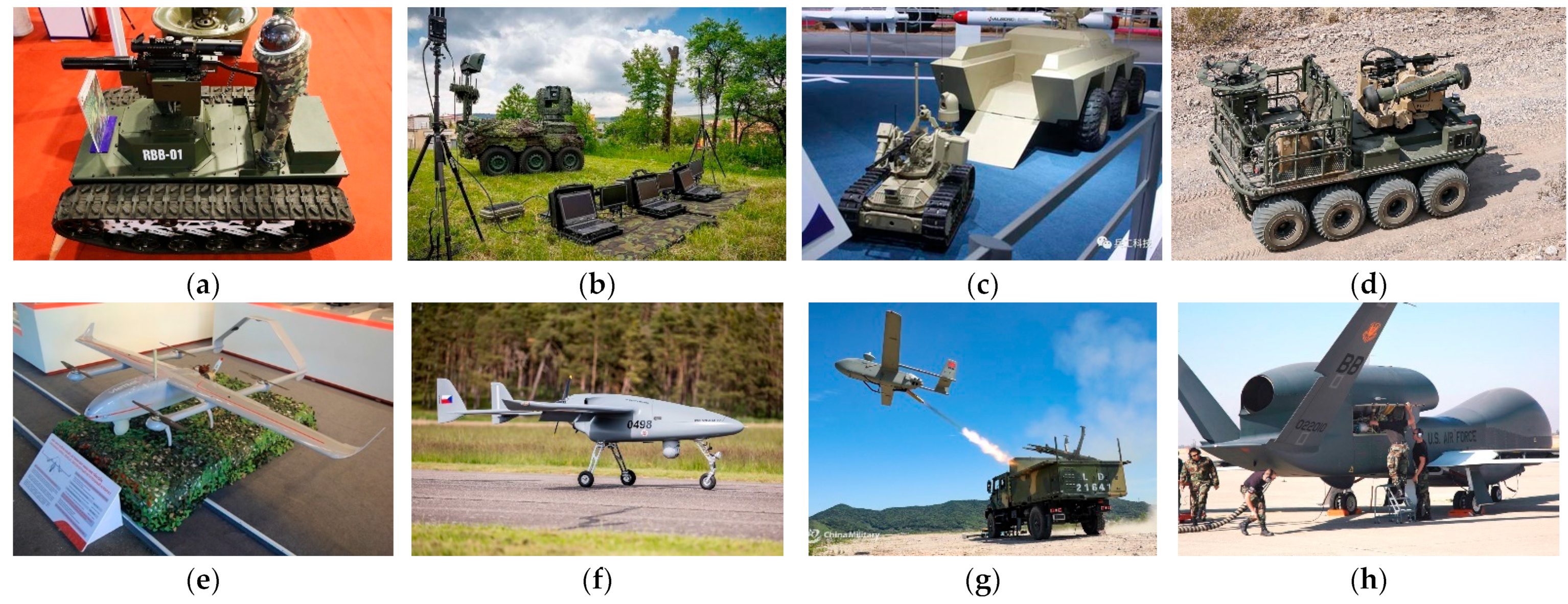
  • Vehicles moving in the air: Unmanned Aerial Vehicles (Systems)—UAV, UAS;
  • Vehicles moving on the ground: Unmanned Ground Vehicles—UGS;
  • Vehicles moving at the sea surface: Unmanned Surface Vehicles—USV;
  • Vehicles moving in the water column: Unmanned Underwater Vehicle—UUV.
In each group, UVs can be classified by using various systems among which the most used one is based on the weight [7]. The classification can be also different between governments and organizations. Table 1 shows the NATO Classification for UASs. This article focuses on small UVs, which do not require high technologies and costs to manufacture and operate. Therefore, they will be more suitable for small militaries and militaries of developing countries. Traditionally, small UVs are powered by internal combusting engines (ICEs). These engines are characterized by not-so-high efficiency, slight hysteresis of dynamic behavior, and low power density in comparison with full-electric drives [3,4,5].
In recent decades, with increasing concerns about environmental and ecological issues, troubles of emission and noise caused by ICE must be considered by many governments and corporations. Since the 1990s, electric vehicles (EVs) and hybrid electric vehicles (HEVs) have been announced as promising alternatives to ICE and got a lot of development attention. They use a concept of hybrid or full-electric drives based on electrochemical batteries, even fuel-cell [3,21,22]. This trend in the transport vehicles has also been applied to UVs, especially small UVs, to minimize these above-mentioned disadvantages of ICE [3,23,24]. Figure 2 shows the efficiency of using Electric Vehicles to reduce carbon dioxide (CO2) pollution. The scenario of comparison is presented in detail in [24]. The results show that using Electric Vehicles (powered by batteries or Fuel Cells) can reduce a large amount of CO2 emissions. In the most interesting scenario, the equivalent amount of CO2 can be reduced from 787 g/km (Coal-to-Liquid fuel) to about 50 g/km (BEVs in low-carbon countries—Austria, Sweden, Norway, Iceland) [24].

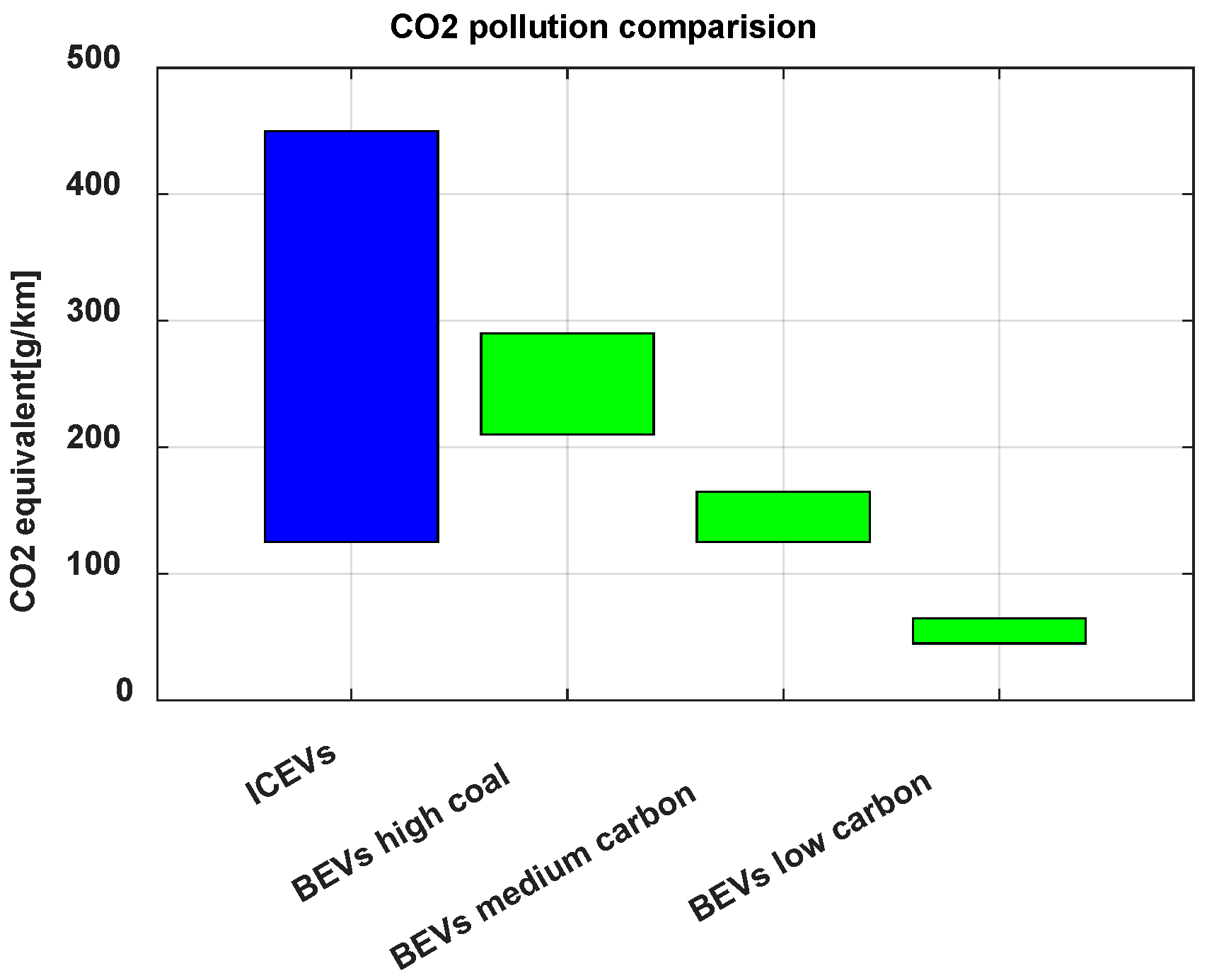
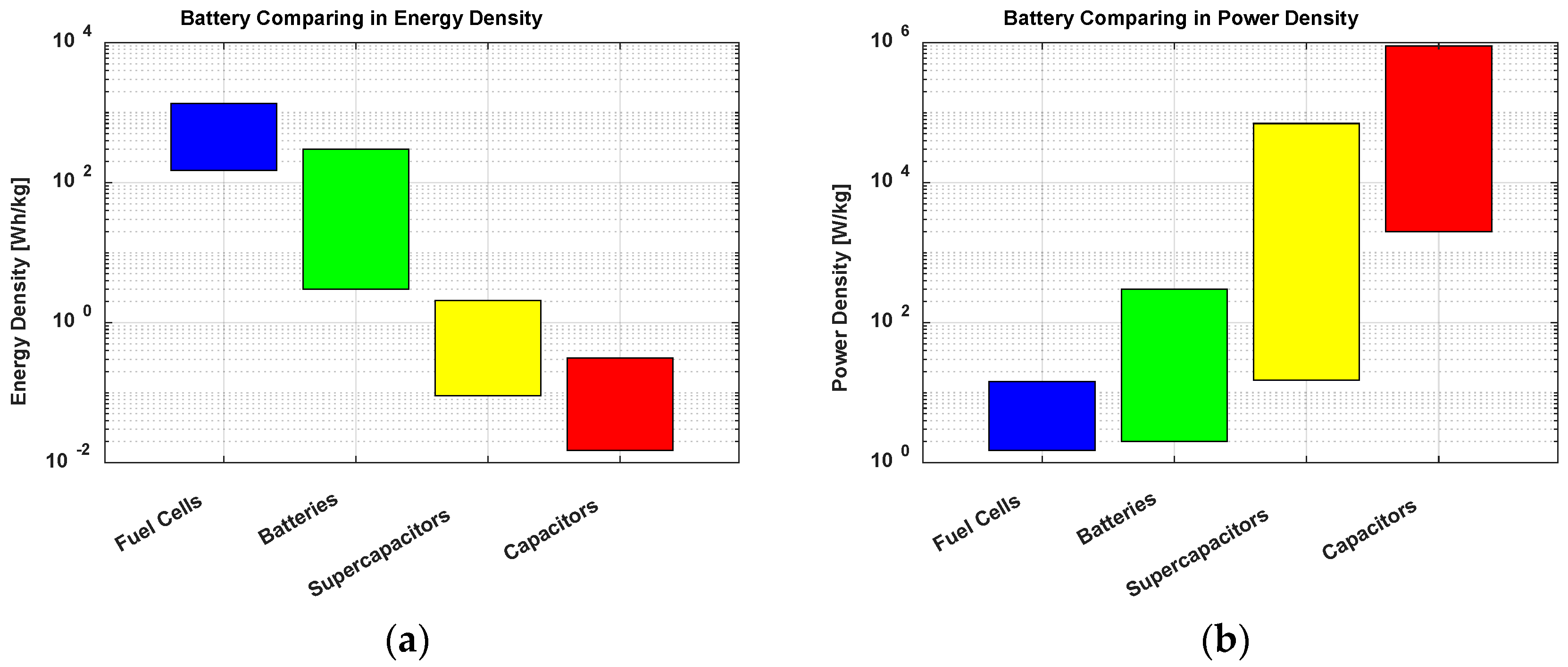
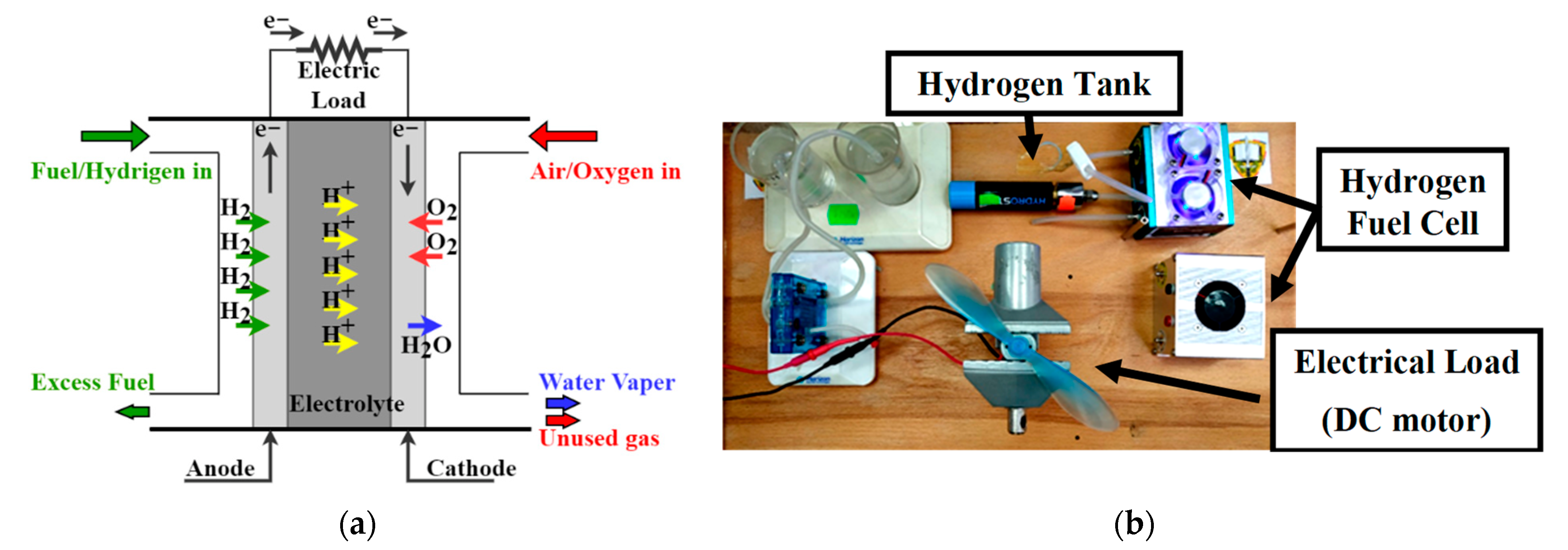
2. Electric Vehicles Power Supply

The electric vehicles are based on the battery’s technologies providing power supply. Batteries can be defined as an electrochemical power source that directly converts chemical energy into electric energy using an electrochemical reaction [25,26]. Because the Carnot cycle dictated by the second law of thermodynamics cannot restrict the electrochemical reactions, batteries can gain more efficient energy conversion [26]. The elementary unit of a battery system is called a battery cell, which consists of three main parts: the anode–negative electrode, the cathode–positive electrode, and the electrolyte—medium for the transfer of electric charges inside the cell
Battery cells are available in multiple shapes and sizes, and the most common shapes are cylindrical cells and wound prismatic cells. Based on the ability to be electrically recharged, battery cells are classified as primary and secondary ones. Primary cells cannot be electrically recharged and then, can be discharged only once. In contrast, secondary cells can be electrically recharged after discharging. Therefore, they can be used in several cycles of charge-discharge (life cycles).
By connecting multiple cells with (approximately) similar properties, we get a (multi-cell) battery that is widely used in the military as well as industrial and commercial applications. Batteries are packaged in various shapes, sizes, and configurations; and are also classified as primary batteries and secondary batteries. The secondary batteries are also called storage batteries or accumulators. Primary batteries are inexpensive, lightweight, and easy to use but have lower capacity. Hence, they are suitable for portable electronic and electric devices such as digital cameras, GPS devices, lightning, etc. [26]. However, secondary batteries are usually heavier but have higher capacity, higher discharge rate, and ability to be recharged. As a result, they are better choices for applications requiring high operating electric current with long operation time. Obviously, in the areas of EVs, secondary batteries are the optimum choice.
The secondary batteries have been used for almost two centuries since the late 1850s. Their technology has been constantly involved in two directions—using high surface area electrodes and using advanced materials [26]. The first secondary battery, which was a Lead-Acid cell with a voltage of 2 V, was introduced in 1859 by Plante. One year later, in 1860, a series of nine connected cells was demonstrated by Plante for the French Academy of Science. Presently, the most common Lead-Acid battery configuration contains six battery cells in series for a combined voltage of 12 V. They are used widely in automotive SLI systems, EVs, HEVs, industrial trucks, aircraft, and other applications.
Since the beginning of the 20th century, Nickel batteries have been developed and used in industrial applications. With higher energy density, power capability, and other advantages, Nickel batteries dominated the rechargeable battery market for aircraft engine starting systems, communications applications, and portable devices during the 20th century [26]. The most used types of Nickel batteries are Nickel Cadmium (Ni-Cd) and Nickel Metal Hydride (Ni-MH). The NI-Cd batteries have significant issues with the toxicity of Cadmium and the so-called “memory effect”. Ni-MH batteries eliminate these issues; however, their rate of self-discharging is larger and increases with the rise of batteries’ capacity. Therefore, at present, Ni-MH batteries are mostly used in the pencil battery form with low capacity.
The century of Nickel batteries came to an end when Lithium batteries were marketed. The first Lithium battery in the market was launched by Sony in 1991 [26]. From the first decade of the 21st century, Lithium battery technologies rapidly took place of the standard power source in multiple fields [3,23,25,26]. Now, various types of Lithium are widely used every day by people all over the world. The most common types of Lithium batteries are LiCoO2, LiFeO4, and LiMn2O4. Lithium batteries are widespread because of the higher cell voltage, longer life cycle, long shelf life, rapid charge capability, no memory effect, broad temperature range of operation, and so on. Table 2 shows the major outstanding features of Lithium batteries over their predecessor.
Recently, the military, aerospace, transportation, and automotive industries have shown an interest in the remarkable Fuel cells technology, which can support the capabilities of existing battery types. In comparison with batteries and supercapacitors—see Figure 3—fuel cells have limited power density but much higher energy density. The other advantage of fuel cell technology is that it is a cleaner technology using alternative fuels such as Hydrogen, Methanol, … [3].
Fuel cells, as well as batteries, are electrochemical power sources that produce electricity by combining a fuel (electroactive material) and an oxidant. The main difference between batteries and fuel cells is that the active materials for fuel cells are provided from an external source that is not an integral part of the device as in batteries. Therefore, a fuel cell can generate electrical energy as long as the active materials are provided [3,25,26]. Based on the types of fuel, fuel cells are classified into two categories: Proton Exchange Membrane (PEM) Fuel Cell and Solid Oxide Fuel Cell (SOFC) [25].
In PEM Fuel cell systems, electrolytes conduct hydrogen ions (H+) from anode to cathode. The fuel source; therefore, can be pure hydrogen or pure H2 or H2 generated from a fuel reformation process. In contrast, the fuel source of SOFC systems is oxygen ions (O2). The SOFC systems have the advantage of having higher efficiency; however, they operate at high temperatures (800–100 °C). Therefore, PEM Fuel cell systems recently are the most promising alternative to ICE and battery system in the automotive, military, and transportation industries. Figure 4 shows a Hydrogen PEM Fuel Cell system in practice, including its structure and power characteristics.
The characteristics of Fuel Cell systems, as shown in Figure 4, are different from the characteristics of batteries. However, they are similar to the photovoltaic system while the output current is dependent on voltage. The output power then is the function of the output current. Therefore, like the photovoltaic systems, the Fuel Cell system requires a power electronic processing block, for example, Maximum Power Point Tracking (MPPT) controller, to acquire maximum efficiency. The mathematical model of Fuel Cell is also an important and knowledgeable topic to design an efficient controller. An example of a mathematical model of a Fuel Cell can be found in [27].
Currently, the usage of Fuel Cell technology is limited by several barriers. The biggest barrier is the high initial cost of the system since the technology has not been produced on a large scale yet. The other issues can be the heat as a by-product, noise (mainly from ventilation), and the limited operability under critical conditions (air impurities, freezing, thawing, underwater, etc.). Figure 4d shows the discharge current of a fuel cell at different loads with temperature dependence. The figure shows that while the differences in currents at a certain load between 20 °C and 50 °C are negligible, the variances between 20 °C, 10 °C, and 0 °C are significant, over 10 times different for each value of current.
Regarding electrochemically power storage and ecological power source, in recent years, there are increasing concerns about the Hybrid Renewable Energy Systems (HRESs), which contain one or several renewable power sources and energy storage solutions such as battery or Fuel Cell systems [28,29,30,31,32,33]. Such a combination can eliminate the disadvantages of each power source by using the advantages of others. In such HRESs, battery and Fuel Cell systems are used to store the generated power to create an autonomous mobile uninterruptible electric power system. On the other hand, renewable power sources can also be used as a power harvesting solution to increase the efficiency and operating time of battery or Fuel Cell systems. Currently, in many countries, one of the most popular and promising renewable power sources is the Photovoltaic (PV) system [29,30,31,32,33,34,35,36,37]. Figure 5 shows the scheme of HRESs based on PV systems. More detailed discussions about these systems can be found in [28,29,30,31,32,33,34,35,36,37].

3. Design of Battery Management System

This article presents a design of a Battery Management System (BMS) for multi-cell Lithium battery packs used in small electric UVs from the hardware and software point of view. The examples of electric UVs, to which the designed BMS is applied, are introduced in [38,39,40,41,42]. One of them is a four-wheel UGV, which is designed to carry a jamming system with a horn antenna [38,39,40]. The power source of this UGV consists of three Lithium batteries, each of which contains seven battery cells in series and a supply voltage of 25.9 V, with a capacity of 5000 mAh. The second one is a small quadrotor UAV designed to perform a variety of investigating and studying tasks in laboratories at the Department of Aviation Technologies, the University of Defence in Brno. This UAV is powered by three Lithium batteries, each of which supplies a voltage of 11.2 V with a capacity 2500 mAh. This chapter also briefly presents the necessity of BMS on a Lithium battery system as the motivation for the design and sets forth requirements for designed BMS. As a theoretical basis, the overview of the State of Charge estimation methods and communication protocols used by the designed BMS will also be presented.

3.1. Motivations and Requirements

Currently, the most popular battery type in portable electronics and EVs is the Lithium battery, especially the Lithium-ion battery [43,44,45]. By means of high cell voltage and high energy density, an individual Lithium cell can be enough to power a portable device such as a telephone, digital camera, etc., for a long enough operation time. However, battery packs are necessary for applications that require higher supply voltage, higher discharge current, and more energy [43,44,45,46]. In an ideal case, all cells of a battery pack must be identical. This requirement is impossible in practice due to different conditions during production, storage, as well as operation.
Other safety-critical issues of batteries include thermal issues, over-charging or over-discharging, over-current, and so on [43,44,45,46,47,48]. Among these issues, thermal issues are considered to be the most critical. Thermal issues can significantly affect the operation as well as the life cycle of batteries [23,49,50,51]. For example, high temperatures can cause combustion and explosion. From a scientific perspective, thermal issues significantly influence the internal electro-chemical of batteries. In [44,50], authors showed the effect of over-charging and over-current on the viability of batteries. The over-charging and over-current also lead to thermal issues because of the increase in the Joule heat [43,44]. The over-discharging does not cause a critical hazard; however, a battery cell can become a “dead cell” after extreme over-discharging. The over-discharging results in the internal electrochemical effects which shorten the batteries’ life cycle and safety [48,52,53]. A more detailed and scientific analysis of these issues, especially from the electrochemical viewpoint, can be found in [43,44,45,46,47,48,49,50,51,52,53].
Multiple accidents caused by improper operating conditions of Lithium batteries were reported; therefore, a BMS is required to monitor and protect the battery against irregular operating conditions. The most famous one was the fire of the Auxiliary Power Unit (APU) using Lithium batteries on a Japan Airlines B-787 on 7th January 2013 [54]. Figure 6 describes the exemplar APU block and the rest of the APU block in the accident.
Because the goal UVs use many battery packs to power their components, the BMS is designed in a distributed topology with one Master module and more Slave Modules. Each Slave module is responsible for monitoring an operating condition such as battery voltage, discharge current, temperatures, or cell voltage of a battery. Based on the obtained data about the operating conditions, Slave modules protect their batteries against cell imbalance. The information about operating conditions and the state of each battery is also sent to the Master module. The Master module will record these data to non-volatile memory such as a microSD card. After that, it will send these data to the control station for purpose of analysis in real-time according to the requirement of the control station. The communication between Slave modules and the Master module is realized in two ways—via Controlled Area Network (CAN) bus or wirelessly. The communication between the Master module and control station must be wireless, using the same 2.4 GHz frequency as Wi-Fi 802.11.
More detailed discussions about BMS can be found in multiple other papers. In [55,56,57], the authors also provided specific overviews and discussions about BMSs, their necessities, and functional requirements. The authors addressed the challenges for BMSs and propounded future possible solutions for these challenges. In [58], the EMI issues of BMS front-end integrated circuits (ICs) for EVs and HEVs are experimentally investigated and discussed. The authors developed a specific test board to test the EMI susceptibility of BMS ICs by direct power injection (DPI) and radiated susceptibility measurement in an anechoic chamber. In [59], an interesting multicell-to-multicell battery equalizer was presented. The equalizer was developed based on a novel bipolar-resonant LC converter, which supports flexible and efficient operation modes with stable balancing power and can greatly improve the balancing speed [59]. The authors also provided mathematical analysis and comparisons with typical equalizer topologies [56].

3.2. Theoretical Basis

3.2.1. State of Charge Estimation

Currently, there has not been any method to measure or compute exactly the State of Charge (SoC) of a Lithium battery, so the SoC can only be estimated approximately based on the parameters of the battery. There are three main methods to estimate the SoC, which are [3,4,5,23]:
  • Open Circuit Voltage (OCV) method
  • Battery Internal Resistance (BIR) method
  • Coulomb Counting Method (CCM) method
The OCV method predicts the SoC of a Lithium battery by measuring its open circuit and comparing it with the discharge curve SoC = f U O p e n   C i r c u i t . Figure 7 presents the typical discharge characteristics of Lithium batteries and shows the discharge curve SoC = f U O p e n   C i r c u i t depends on discharge current and temperature. Therefore, it is impossible to achieve a precise discharge characteristic for estimation. In addition, the OCV method requires the battery to be disconnected from the external circuit. For these reasons, the OCV method is not chosen for the designed BMS.
By applying the second method, named BIR, the SoC is estimated based on the dependence on the battery’s internal resistance. In this test, the battery discharges with the current up to several hundred amps in a short time of some milliseconds. The internal resistance R of the battery is then calculated by Equation (1), where I is the discharge current, and U0 and U1 are battery voltages during discharging and after discharging. Hence, the BIR method requires special gauging instruments that are highly accurate and can operate under special conditions. As a result, this method cannot be used in our system.
R = U 0 U 1 I
CCM computes the remaining accumulated electric charge by counting the number of flowing charges which are the integral of discharge current over time. Theoretically, the ratio of the remaining accumulated electric charge to the nominal capacity of the battery itself is the SoC the of battery. In practice, due to the non-ideal of components, circuits, and technologies, the efficiency of the process is limited by the factor µ. For Lithium batteries, µ can reach up to 94%. Given the initial state SoC0 of the battery at time t0, the SoC of the battery at time t is estimated according to Equation (2), where I is the discharge current, and Q0 is the nominal capacity of the battery.
SoC = SoC 0 t 0 t I × Δ t μ × Q 0
This method is the most suitable for the designed system because the necessary parameters can be measured with acceptable accuracy by the sensor system and microcontroller. CCM is also the most common method used on portable medical, military, and commercial devices.
The charging and discharging currents of a battery are standardized by the so-called C-rate. A C-rate of 1 C is known as a one-hour charge/discharge; 0.5 C is a two-hour charge/discharge, and 2 C is a half-hour charge/discharge [60]. Figure 7 shows that the charge/discharge currents significantly affect the operation of the battery. Due to the internal resistance of the battery, high C-rates cause high Joule heat generation, which may lead to thermal issues. Therefore, the C-rate of a battery must be limited. For Lithium batteries, the recommended limit is considered 1 C [60,61]. In [62], the authors conducted a number of experimental analyses and concluded that the maximum C-rate could be 3–5 C for anodes and 10 C for cathodes.

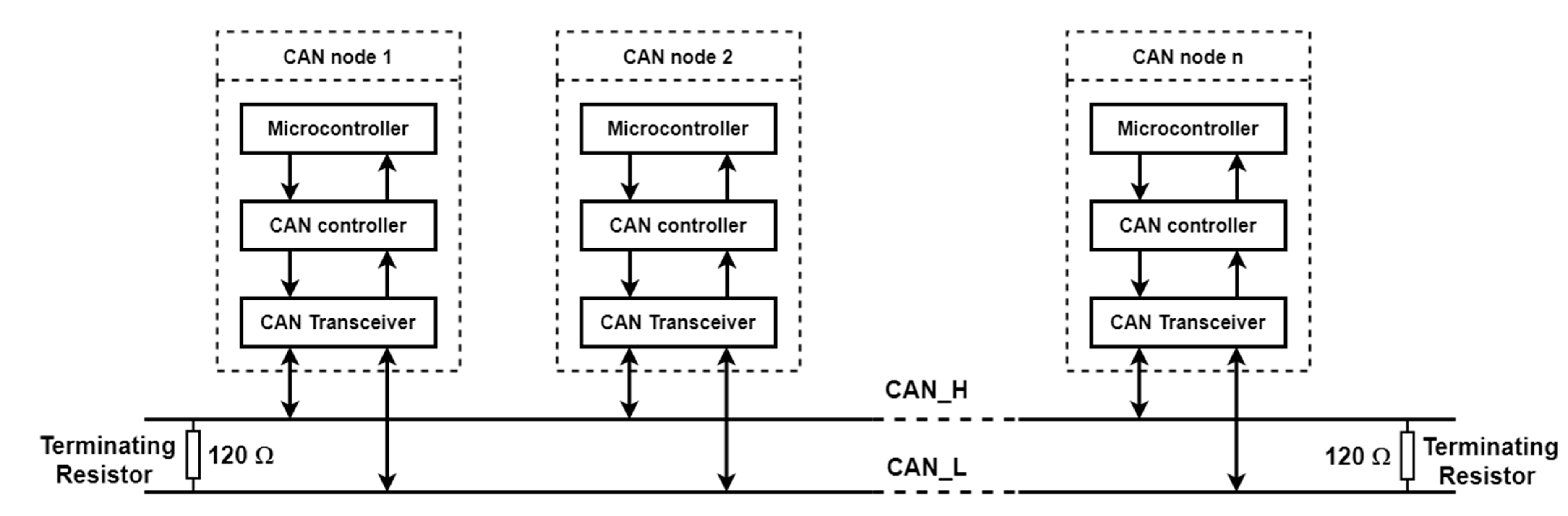
3.2.2. Controlled Area Network

Controlled Area Network (CAN bus) is a massage-based communication protocol which is developed for the in-vehicle network in 1983 [63,64,65,66,67]. CAN bus network is a highly reliable, inexpensive, and real-time network that allows multiple CAN devices to communicate with each other. With an uncomplicated structure, as shown in Figure 8, CAN system has great advantages regarding flexibility, ability to extend, and wiring cost [63,66]. In the automotive industry, CAN bus is one of the most common protocols for vehicle monitoring and controlling systems [63]. Besides this, CAN bus is an excellent choice for electrical work and communication in harsh environments [66,67]. The use of CAN bus; therefore, has been continuing to increase in other industries, such as aerospace, robotics, and automation instrumentation [67]. Due to these advantages, the CAN bus is chosen as one of the communication protocols used in our design. As shown in Figure 8, each CAN node contains a microcontroller, CAN controller, and CAN transceiver. In some microcontroller families, for example, the ESP32 family, the CAN controller is an integral part of the microcontroller. However, other microcontroller families, for example, the AVR Atmega 328 family, do not have an integrated CAN controller but require an external one.

3.2.3. Internet of Things

Internet of Things (IoT) can be defined as a concept that describes a network of interconnected devices enabling new forms of communication between people and things, as well as between things themselves [68,69,70]. The 21st century is considered as “Internet Century” since the Internet Boom affects every aspect of life. This deep fact opens up opportunities to connect every physical object to share information [68,70]. With the rapid development of related technologies, like information technology, computer, and computing technologies, as well as the communication and informatics infrastructure, over the past few years, IoT has become one of the fastest-growing and most important technologies in the Internet century. IoT allows the “Things”—which are in practical devices, instruments, sensors, embedded systems, and so on—to become smarter and be able to communicate with people all over the world via the Internet. People, using IoT, also can monitor, and control Things wherever, whenever the via Internet. The most important and interesting applications of IoT can be mentioned as:
  • Smart Homes and Cities
  • Healthcare Monitoring
  • Environment Monitoring
  • Automotive Industry
  • Smart Industry and Agriculture
  • Energy Management
Regarding the purpose of monitoring and sharing information, applying IoT to the BMS is also a useful upgrade. The information about the state of batteries and operating conditions can be obtained by a low-cost, simple system (in our case, a microcontroller-based BMS). After that, the data can be sent to a more powerful workstation to perform more complex processing and analysis.

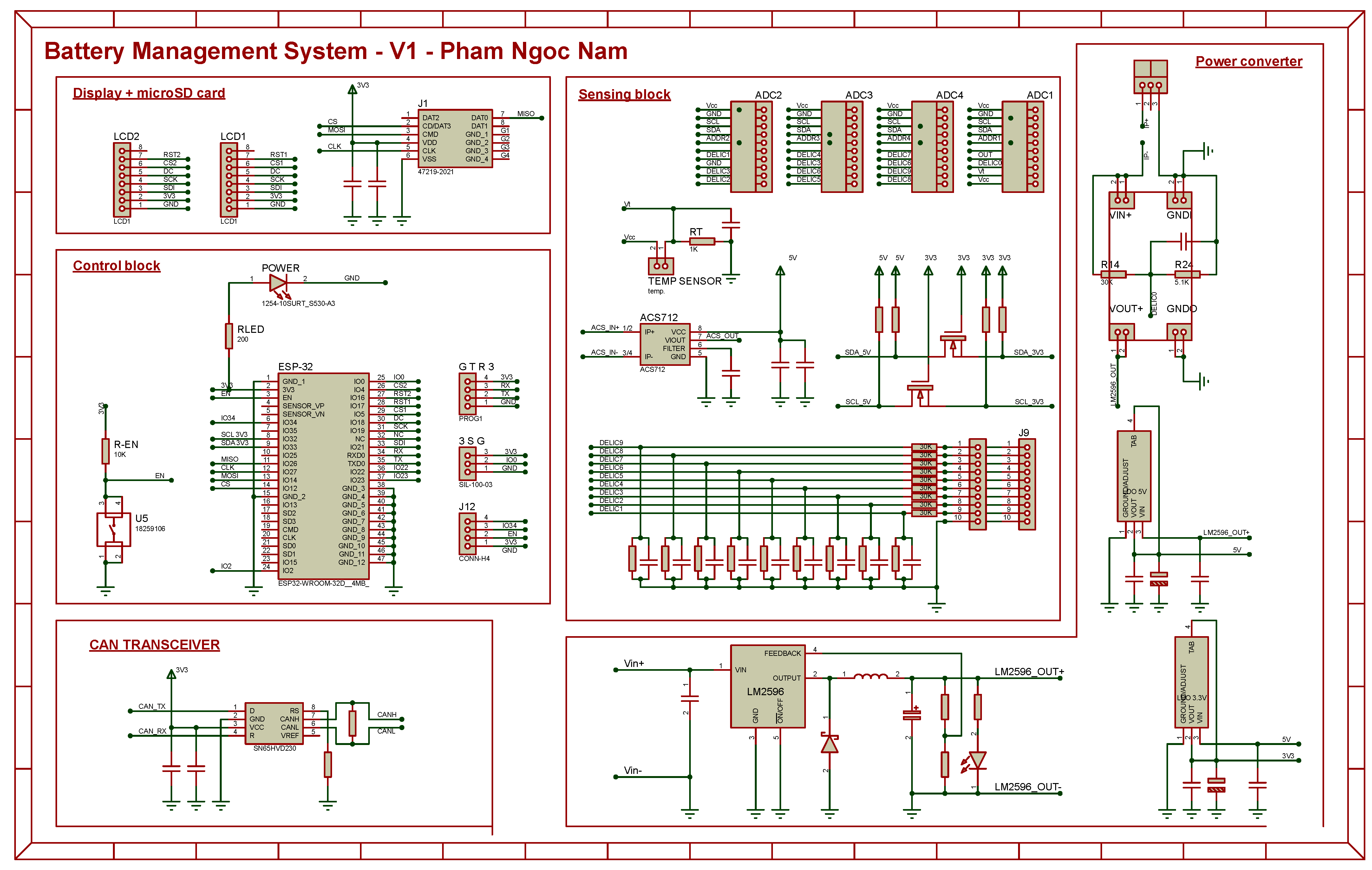
3.3. Hardware Design

Slave Modules oversee the operating conditions of battery packs, protect them against critical conditions, and send the information about battery packs to the Master Module. Therefore, the hardware of a Slave Module contains 5 main blocks:
  • Control block—microcontroller, control the entire system to perform its missions;
  • Sensing block—sensor systems, monitor operating conditions of the battery packs;
  • Balancer block—electronic circuit, protect battery packs against cell imbalance;
  • Power converter—DC/DC converter, power the whole system;
  • Peripheries block—Auxiliary block, indicate, and display the state of system.

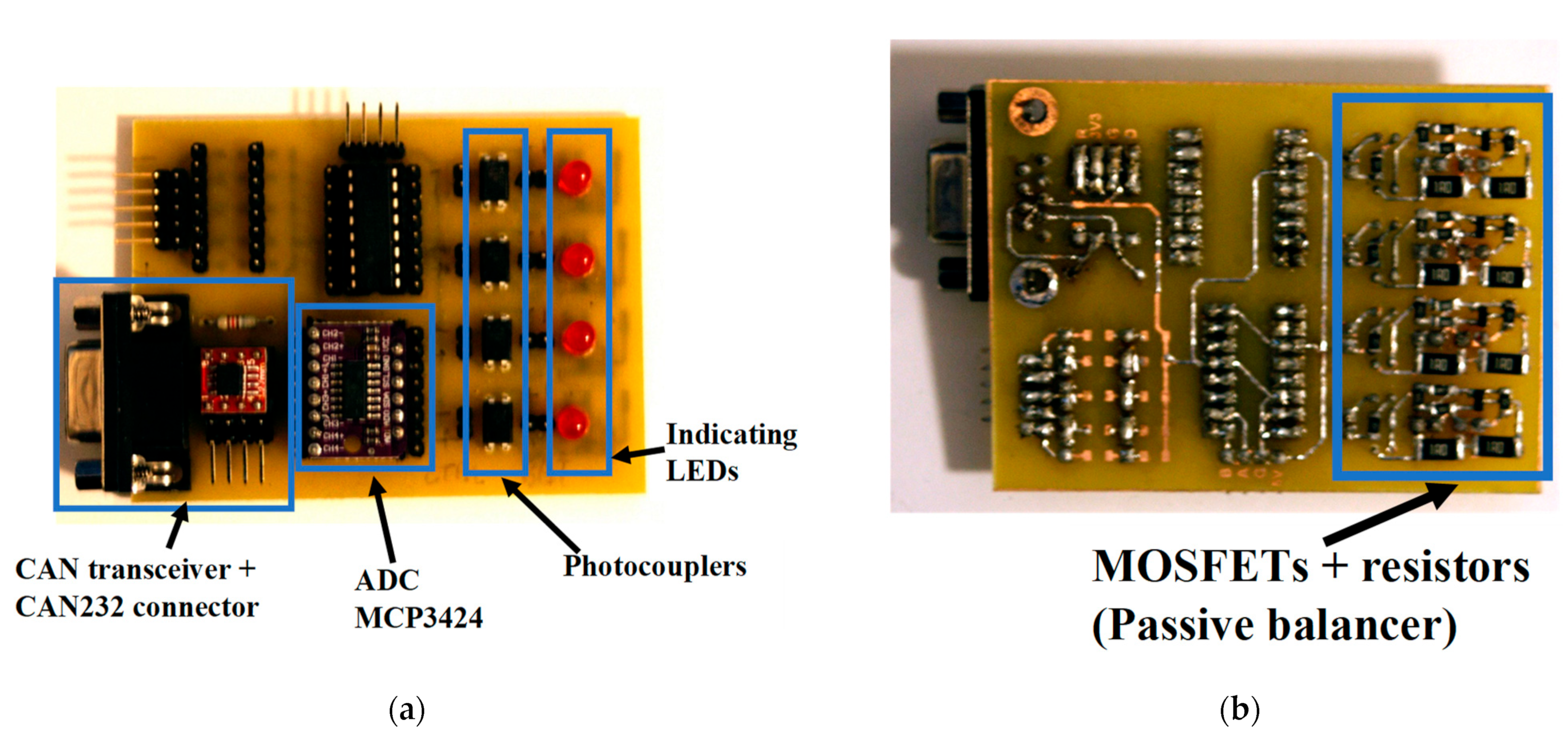
3.3.1. Control Block

In fact, the control block is a microcontroller. The reason is that microcontroller can operate its functions based on a pre-programming plan. The functions of the microcontroller can be easily changed by changing its program. The control block must have the ability to communicate with other blocks to control their functions. This requirement is also easily fulfilled by a microcontroller since it usually has several integral peripheral interfaces such as I2C, SPI, UART, and so on. Another requirement that slave modules can wirelessly send the data to the Master module is usually realized by using a dedicated wireless communication module such as HC-05 and HC-06 for Bluetooth, or NRF24L01 for the 2.4 GHz band. In our design, the chosen microcontroller for the control block is the ESP32 family from Espressif Systems company, which has integral communication protocols Bluetooth, Wi-Fi, and ESP-NOW. This advantage of the ESP32 family allows for minimizing the number of components. Regarding the performance, the ESP-32 family also has great benefits with a dual-core 32-bit LX6 microprocessor, being clocked at up to 240 MHz, and the ability to perform up to 600 DMIPS. The dual-core microprocessor allows the system to operate more complex tasks at the same time and fasten the process of the system.

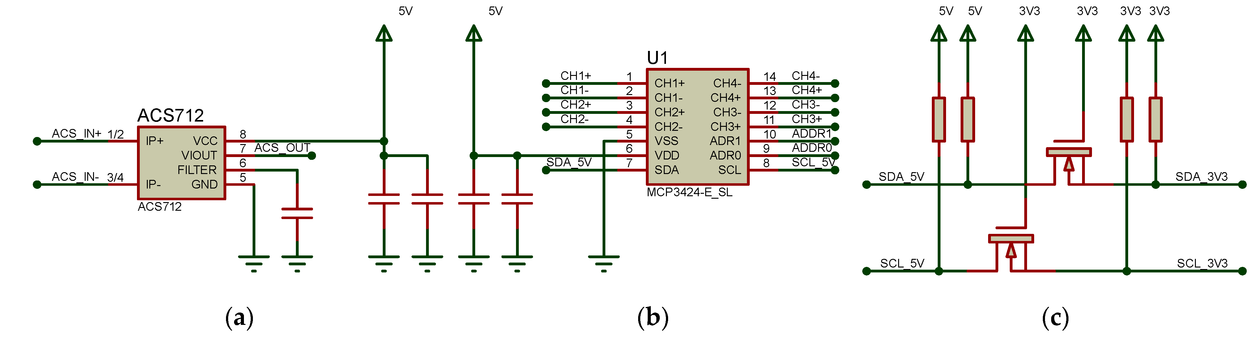
3.3.2. Sensing Block

The sensing block contains sensor systems that monitor the operating conditions of battery packs and estimate the SoC of batteries. As mentioned above, the system estimates the SoC by using the CCM method. Therefore, the important parameters that the sensing block must be able to overview are battery voltage, cell voltage, charge/discharge current, and temperature of battery packs. To measure charge/discharge currents, there are several types of currents with different underlying physical principles, such as Ohm’s law of resistance, Faraday’s law of induction, Hall effect, Faraday effect, … [71]. For the design of Slave modules, the Hall effect current sensor ACS712 is chosen because of its small size, large sensing range, low offset, and high precision. An application circuit of ACS712 is shown in Figure 9.
For temperature sensing, there are three main types of sensors: thermocouples, thermistors, and integral thermal sensors. Integral thermal sensors are easy to use with a standard interface to communicate with microcontrollers, but their accuracy is lower and the sensing range is smaller than the others. Although the newer technologies allow higher accuracy, the cost is also higher. Besides this, the thermal couples are advantageous because they do not require a power supply and have a large sensing range. However, their accuracy is smaller than the thermistor, and the output voltage is usually in the millivolt range. Thus, they require a high precision component in the output. In addition, the very large sensing range of thermal couple is redundant for the BMS system. Last but not least, the thermistors are the most suitable option for our system due to their large enough sensing range, simple required circuit, and high stability. The thermistor is a thermally sensitive resistor. By measuring its resistance (using a simple voltage divider), the temperature is sensed. According to the dependence of its resistance on temperature, the thermistors are classified as:
  • Thermistor with Positive Temperature Coefficient—PTC thermistor—resistance increases with rising temperature;
  • Thermistor with Negative Temperature Coefficient—NTC thermistor—resistance decreases with rising temperature.
Dependence of the temperature T (in Kelvin) on the thermistor’s resistance R is given by Equation (3), where R0 is reference resistance (resistance of the thermistor at 25 °C), A, B, C, D are temperature coefficients.
1 T = A + B × ln R R 0 + C × ln R R 0 2 + D × ln R R 0 3
Under common operation conditions, the third and fourth operands can be ignored. The equation then can be reduced to
1 T = 1 T 0 + 1 β × ln R R 0
T = 1 1 T 0 + 1 β × ln R R 0
where T0 = 25 °C or 298.15 K is a reference temperature, at which the thermistor’s resistance is R0; β is the standard temperature coefficient of a thermistor.
From the above analysis, the most important part of the sensing block now is Analog to Digital Converters (ADCs), which are responsible for measuring battery voltage, cell voltage, the output voltage of the Hall effects current sensor, and drop voltage on the thermistor. ADC block is the basic feature of each microcontroller. However, the integral ADCs of a common microcontroller are not good enough for serious applications because of their low resolution and accuracy. Especially, ADC block with poor linearity is considered as Achilles’ heel of the ESP32 microcontroller family. Therefore, it is necessary to use dedicated ADCs to achieve acceptable accuracy. In our design, the MCP3424 ΔΣ ADC is chosen. MCP3424, which is an 18-bit ΔΣ ADC with four differential inputs, has a great advantage regarding noise issues. Other remarkable features of MCP3424 are low consumption, highly accurate onboard reference, and an onboard programmable gain amplifier. For communication with the microcontroller, MCP3424 is equipped I2C interface with 2 external device address pins, which can be set to a logic high, low, or left floating and allow, therefore, eight possible addresses. The application circuit of MCP3424 is also shown in Figure 9.
While the microcontroller ESP32 operates with a 3.3 V logic level, Hall effects current sensor and ADC MCP3424 operate with a 5 V supply voltage and 5 V logic level. As a result, it is necessary to design a logic level shifter for communication between the microcontroller and sensing block. The simple logic level shifter using N-channel MOSFET is also given in Figure 9.

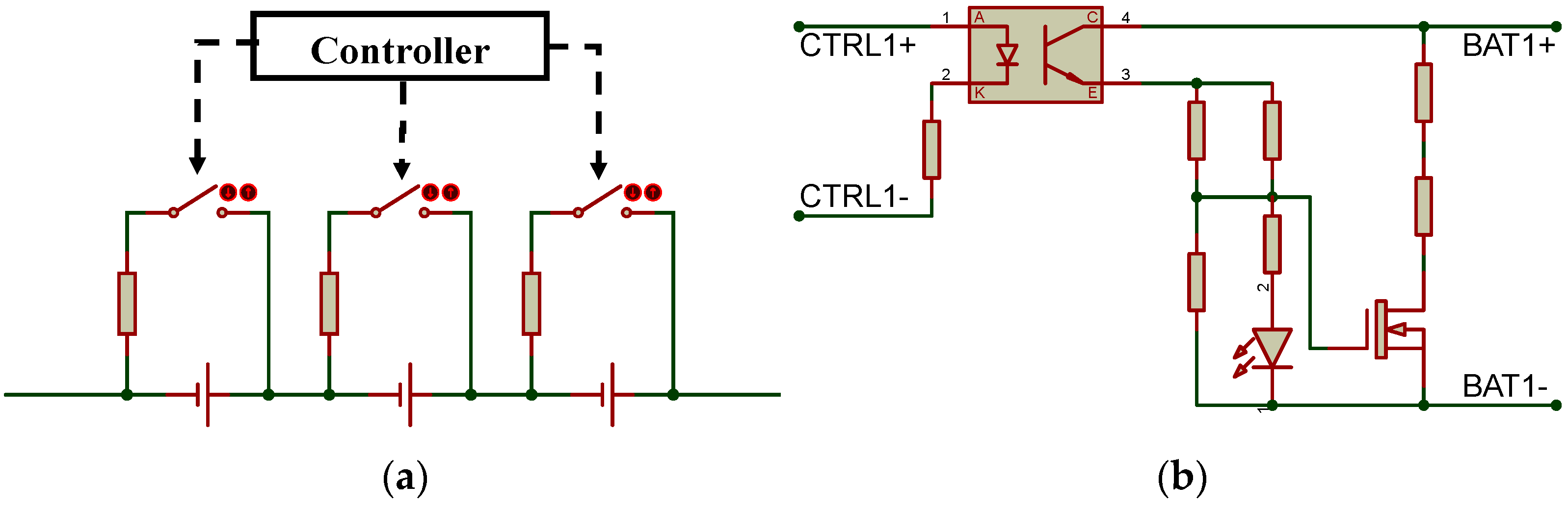
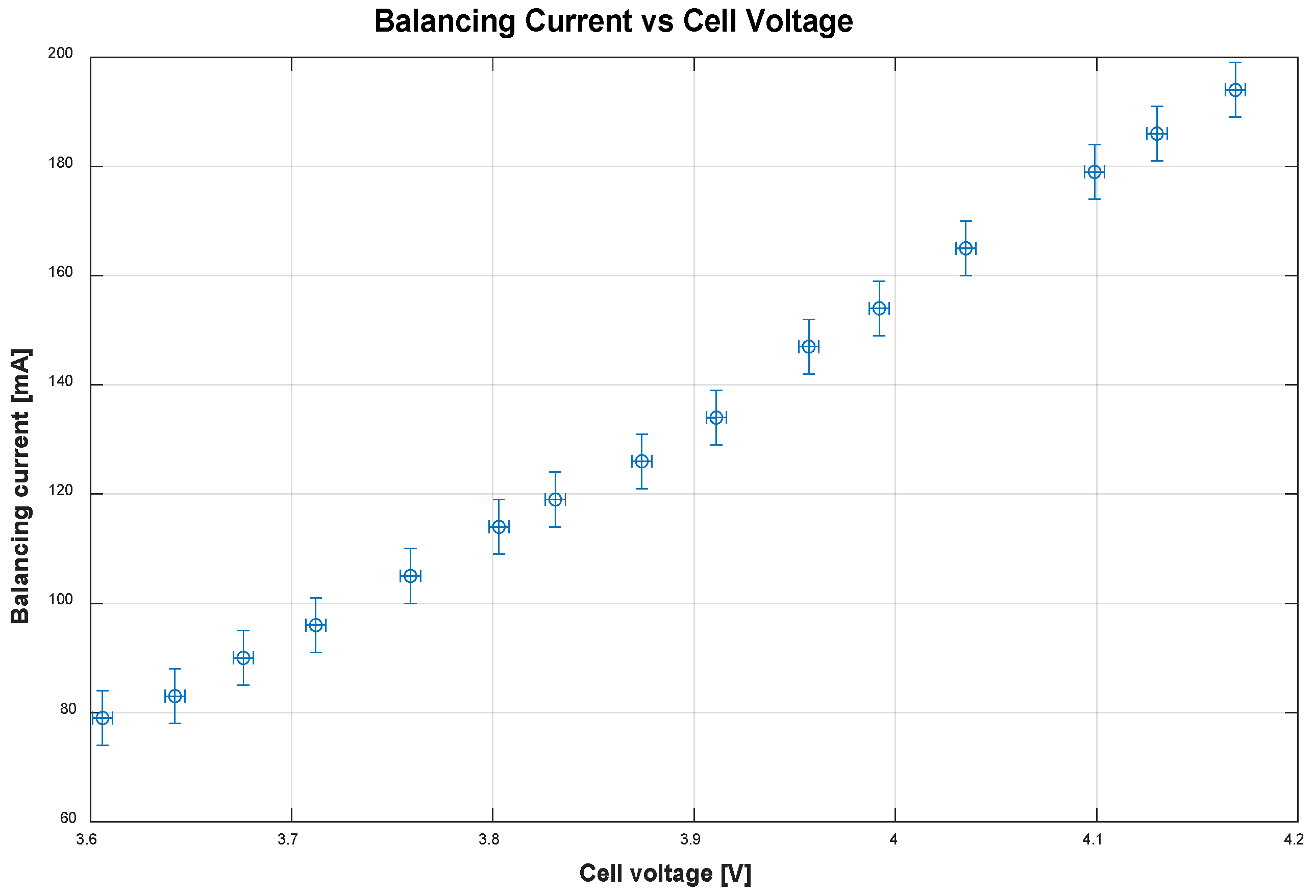
3.3.3. Balancer Block

Based on the cell voltage measured by the sensing block, the control block must control the balancer block to protect the battery against cell imbalance. The cell imbalance that is an essential factor affecting battery life can be caused by internal and external factors [72,73,74]. The internal factors can be a variance in manufacturing, technologies, or storage. The external sources can be the thermal gradient between different cells, which can cause the different self-discharge rates of the cells [73]. The balancer is an electronic circuit that balances the voltage between different cells of a battery pack. The balancer system for Lithium batteries can be classified into two main groups
  • Passive balancer: the electric charges from a cell with higher voltage are removed through a resistor;
  • Active balancer: the electric charges from a cell with higher voltage are delivered into a cell with lower voltage.
Obviously, an active balancer has higher efficiency since there is no thermal power loss. However, the active balancer requires a more complex control algorithm and more complex electronic circuit, resulting in higher cost and longer time to develop [73,74,75]. Therefore, the passive topology of the balancer is chosen for our design. The passive balancer uses Shunting resistors to balance the cell voltage. Figure 10 also shows two methods of passive balancer.
  • Fixed Shunting Resistor: Each battery cell is directly connected to a similar number of resistors. This method does not require any control algorithm, but it has continuous thermal power loss and is usually used as overcharge protection in Lead-Acid and Nickel Battery [75];
  • Switch Shunt Resistor: Each battery cell is connected to the Shunting resistor via a switch. The switches are controlled so that the cell with the highest voltage is connected to the resistor while other cells are disconnected from the resistor.
The principle and design of a balancer block are shown in Figure 10.

3.3.4. Power Electronics Converter Block

The power converter block converts the battery voltage from several dozens of Volts to 5 V and 3.3 V to power the whole system. In the design, the power converter block contains DC/DC converters (voltage regulators). Based on the operating principle, voltage regulators can be classified as Linear voltage regulators and Switching voltage regulators.
A switching regulator, as its name implies, uses a switching element to transform the input voltage level into another voltage level. Because of switching characters, the output voltage has a pulsed form and is smoothed by a capacitor, inductor, or more complex circuit. This property causes the main disadvantages of switching voltage regulators since it requires complex design and more external components, and the output is less stable with more noise. The major advantages of switching voltage regulators are high efficiency with low heat by-produce and the output voltage can be greater than the input voltage.
In contrast, a linear regulator uses linear components to regulate the output. In some situations, a linear regulator is also called a series of regulators because of this series property—the input current and output current are the same. Therefore, the efficiency of a linear voltage regulator is equal to the ratio of output voltage to the input voltage. Due to the required minimum voltage drop on itself, a linear regulator usually has small efficiency and cannot supply a high current. The main advantages of the linear regulator are simple configuration with few external parts and smooth output voltage with low noise.
Regarding the accuracy of the sensing block and control block, a stable supply voltage is required. Therefore, in the design, a combination of two voltage regulator types is used to achieve high efficiency and stable, low noise output voltage to power the whole system. The used switching regulator is an integrated circuit (IC) Switching Step-Down Regulator LM2596 with adjustable output voltage. The liner regulator part contains ICs Linear Regulator AMS1117 with 5 V and 3.3 V fixed output voltage.

3.3.5. Peripheral Block and Master Module

The Master module has a less complex hardware design as it does not directly perform the measurement and equalization functions. Therefore, it contains only the control block, power converter block, and peripheral block. The control block and power converter block of the Master module and Slave modules share the same structure. The peripheral block of both Mater and Slave modules contains a display and LED diodes that indicate the necessary information as well as a CAN transceiver and connector for communication between individual modules. The only different part is that the Master card contains a microSD card slot. The display and LED diodes are optional components and can be omitted to reduce system power consumption. The CAN transceiver used in our design is the SN65HVD230, which operates with a single 3.3 V supply for compatibility with the ESP32 microcontroller. The communication between the microcontroller and microSD card is performed via Serial Peripheral Interface (SPI). Electrical schematics for the connection of all systems, without balancer blocks, are given in Figure 11.

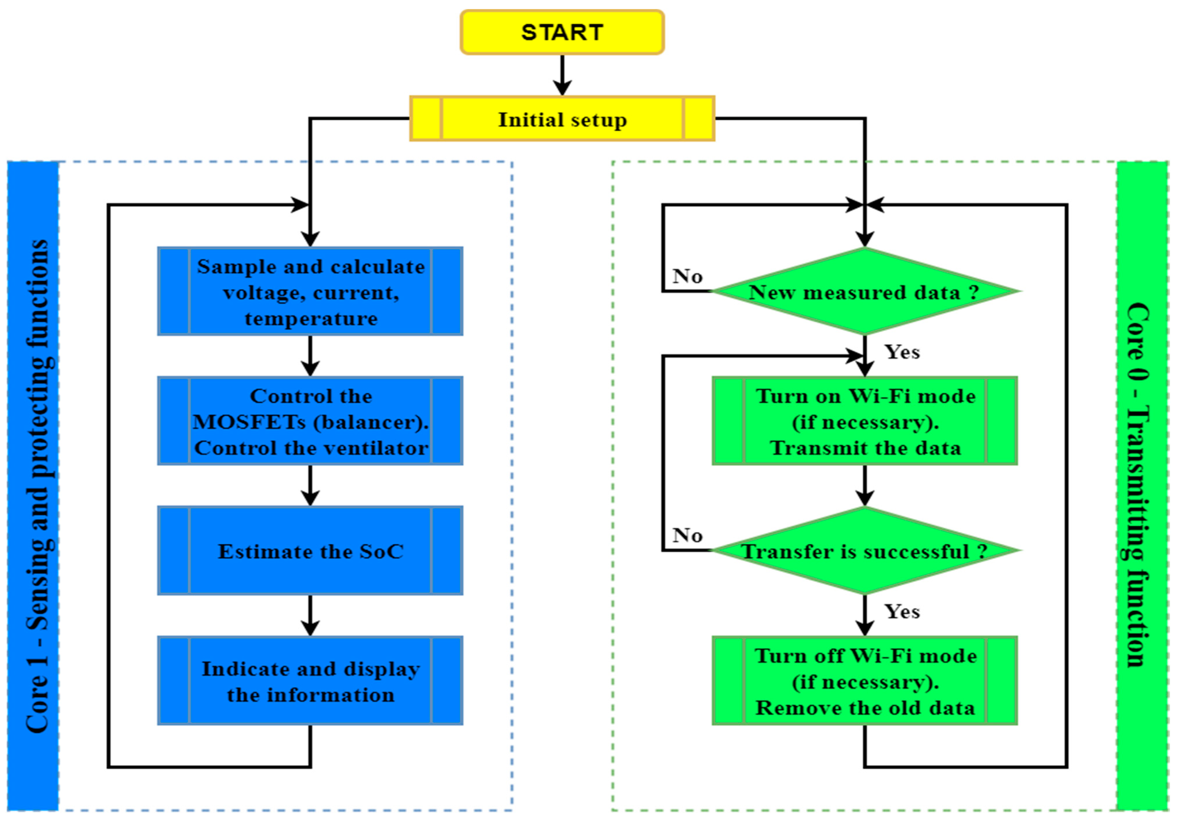
3.4. Firmware Design

Functions performed by the control block are categorized into two main groups of functions:
  • Sensing and protecting functions;
  • Transmitting function.
Due to the reliability requirement, these two groups must be independently performed. The reason is that the instability of the communication channel can cause some delays or even the loss of some transferred data. In this case, the lost data must be retransmitted. Unless two groups of functions are performed independently, the collision will occur, and the functions will not be performed as intended. This requirement confirms again the advantages of the ESP32 microcontroller. This microcontroller has a special feature called dual-core, so it is capable of performing the two groups of functions in parallel. The first core, called Core 1, oversees the sensing and protecting functions. The information obtained by Core 1 is stored in the internal memory. The second core, named Core 0, is in charge of performing the transmitting function. If the transfer is realized without any errors, Core 0 removes the transferred data from internal memory and transmits other measured data. In the case of wireless communication between modules, the power consumption of the ESP32 microcontroller with the Wi-Fi functions on is much greater than that with the Wi-Fi functions off. Therefore, to reduce power consumption between successful transfers, the Wi-Fi functions of ESP32 will be disabled. The simplified algorithm flowchart of the microcontroller’s firmware is given in Figure 12.

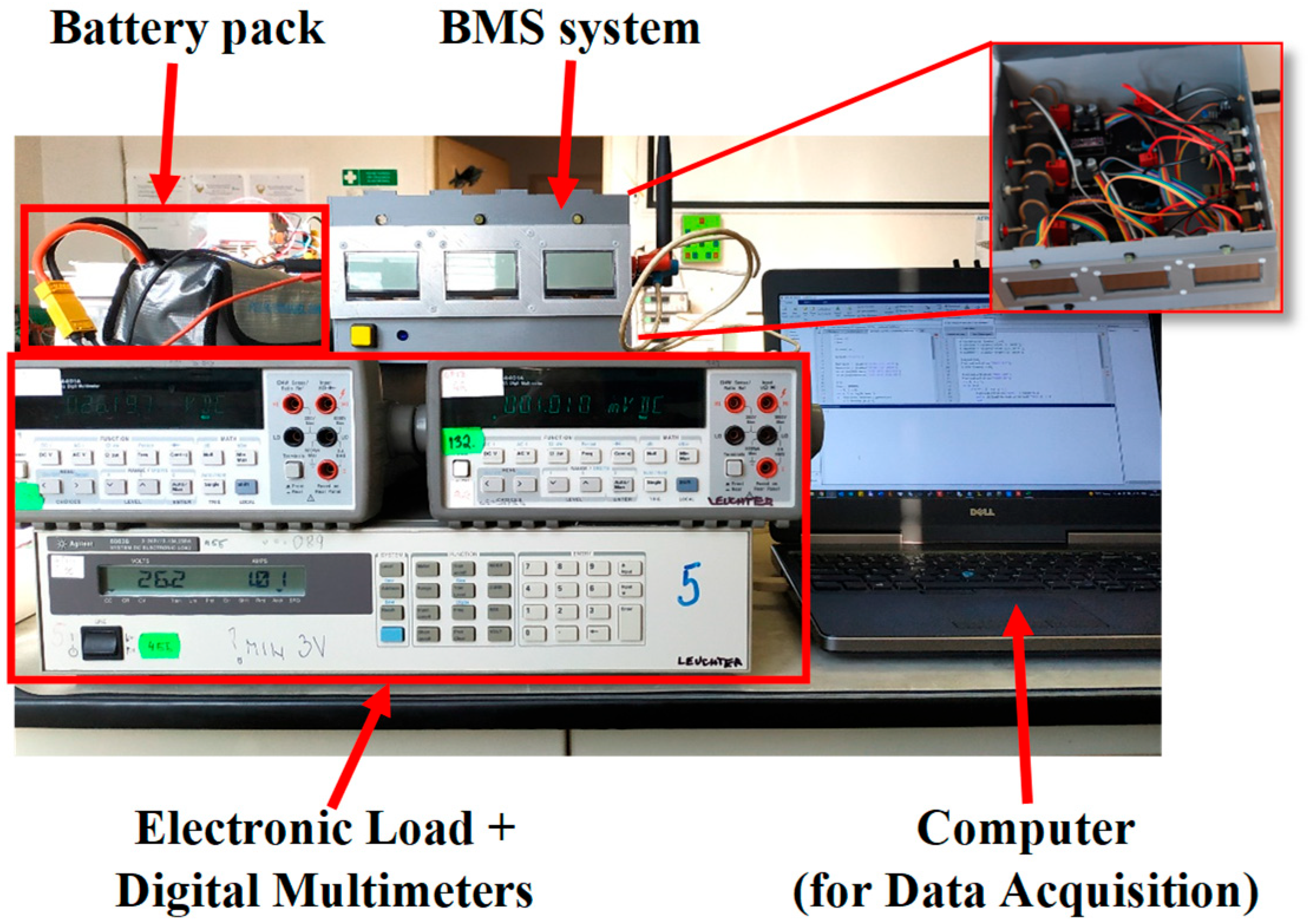
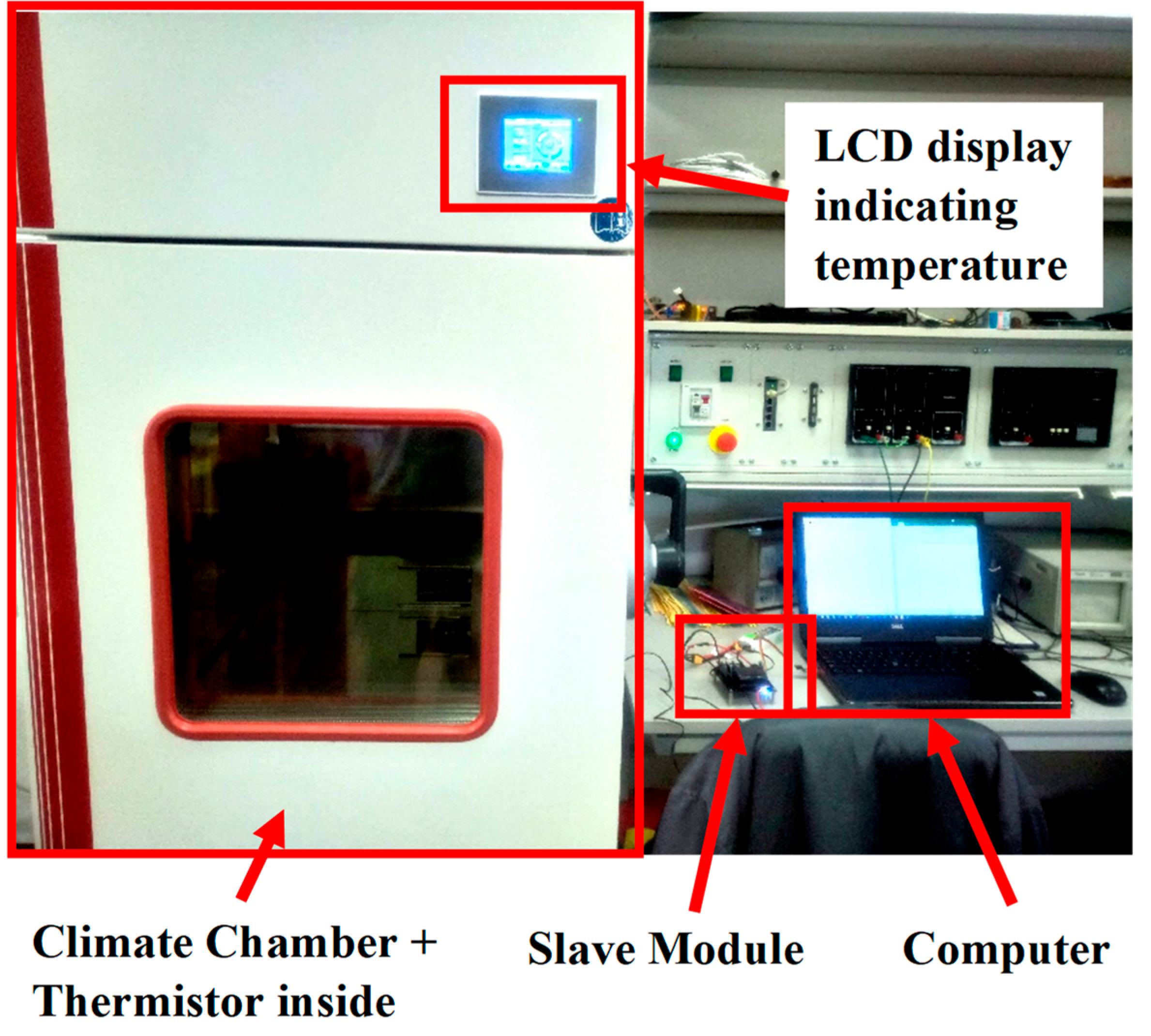
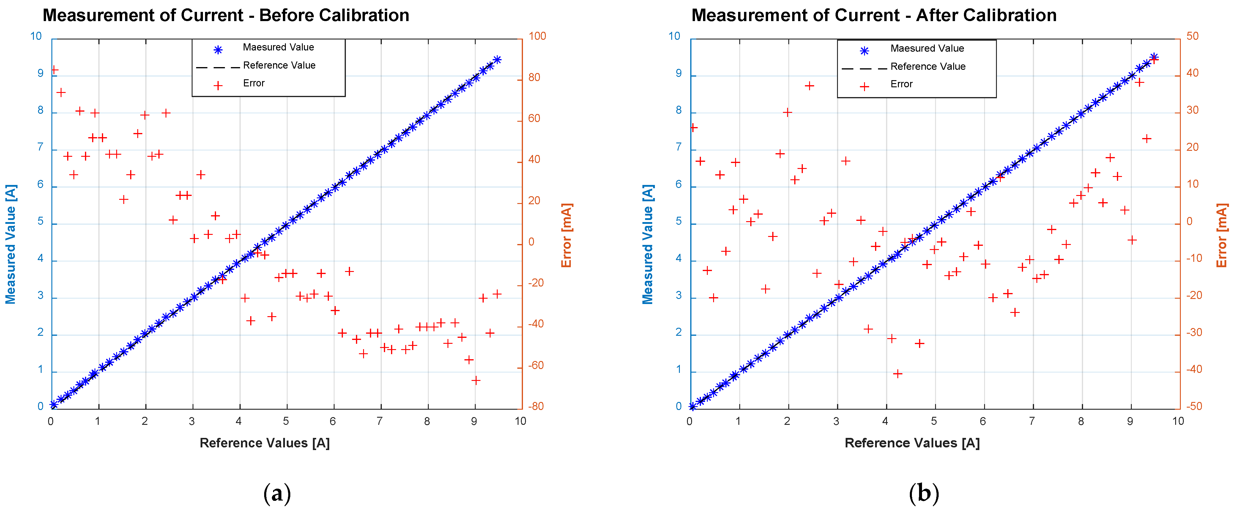
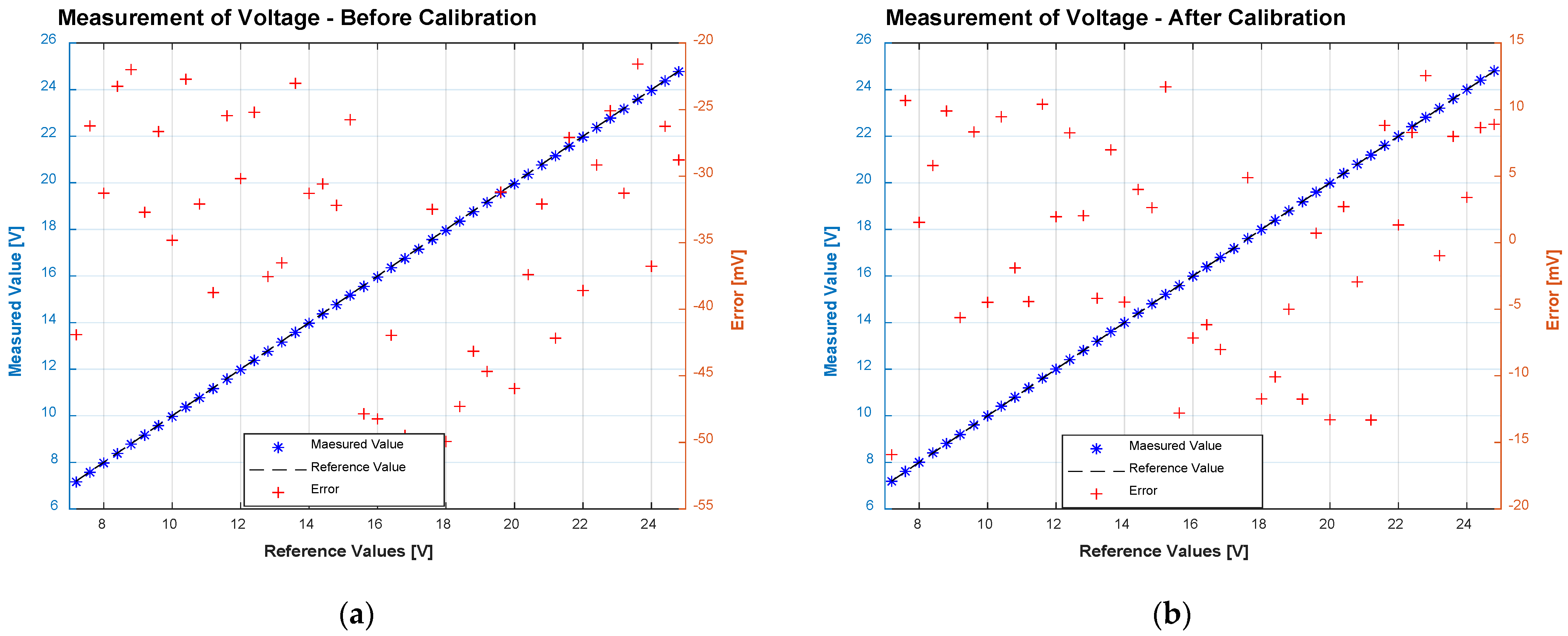
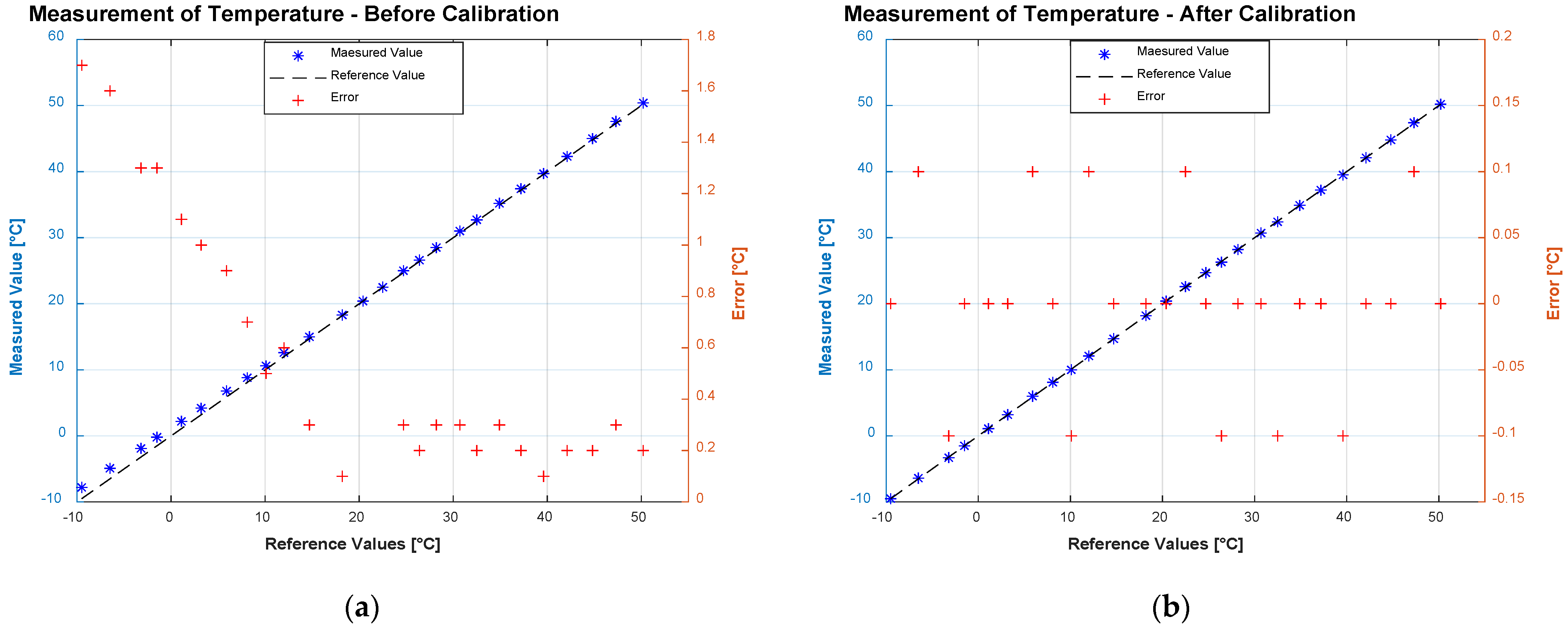
4. Verification and Discussion

The required functions of the designed BMS are verified by several testing and experiments. Firstly, the most important function—protecting the battery against cell imbalance—is verified. For the testing, a prototype of the Slave Module is realized. The prototype contains a module of ADC 3424, a CAN transceiver SN65HVD230, a connector CAN232, and a balancer circuit for a four-cell battery pack. For safety, the microcontroller is connected to the prototype via a prepared connector. The prototype is shown in Figure 13. The battery is simulated by a laboratory DC power supply E3633A. The dependence of balance current on cell voltage is measured and shown in Figure 14. The characteristic shows that the balancing current increases with the rising of cell voltage. For a Lithium battery, the voltage of each cell is in the range from 3.6 V to 4.2 V, and the balancing current is in the range of 80 mA to 200 mA.
Then, the sensing block is calibrated and its accuracy after calibration is verified. The experiment setups for calibration and accuracy testing are given in Figure 15 and Figure 16. Figure 15 shows the experimental setup for the measurement of current and voltage. A battery pack is connected to the BMS system and an electronic load. To calibrate the Hall effect current sensor, the digital multimeters are also connected to the system to measure discharge current. The value measured by a multimeter is considered a reference value for calibration. To measure voltage, a laboratory DC power supply is connected to the BMS system. The supply voltages measured by BMS are compared with the output voltage of the power supply. All the instruments can be controlled by a computer using Standard Commands for Programmable Instruments (SCPI) for automation of measuring. Figure 16 shows the experiment set up to measure temperature. The experiment uses a climate chamber to set the reference values of temperature, which are used to compare with values measured by Slave Modules.
All the experimental results are given in Figure 17, Figure 18 and Figure 19. By using calibrated coefficients, the errors of measurements are significantly reduced. After calibrating, the BMS has capabilities of:
  • Measuring current with absolute error ± 50 mA
  • Measuring voltage with absolute error ± 15 mV
  • Measuring temperature with absolute error ± 0.1 °C
The function of estimating batteries’ SoC is also calibrated and verified. After calibration, the chosen value for the coefficient of efficiency µ in Equation (2) is 94%. The estimated values of SoC during seven processes charge-discharge are shown in Table 3. The data shows that with the proper value of efficiency coefficient, the BMS can estimate the SoC with an error smaller than 5%.
Finally, the communication between BMS and workstation using IoT technology is verified. Figure 20 shows the user interface of the application Google Sheets. The data measured by BMS systems are successfully transferred via the Internet to this application. Then the users with permission can access these data wherever, whenever for further uses. The uses of other IoT platforms in the BMS system also were introduced in [4,5].
Thus, it is obvious that the designed BMS fulfills all the requirements with acceptable accuracy. More accuracy of BMS can be gained by using more precise components and more proper calibration coefficients. It is also necessary to replace the passive balancer with an active balancer to gain higher efficiency and reduce the power loss.
The designed BMS is actually a Commercial off-the-shelf (COTS) system, which is based on a microcontroller and common ICs such as ADCs, linear and switching regulators, and current and temperature sensors. Such a design allows easy, cheap, and fast manufacturing, maintenance, repair, or upgrading. In this period of chip shortage, such a COTS design is one of the most promising solutions [76] because the concept of the designed system can be applied to almost types of microcontrollers, ADCs, sensors, etc.
The use of a microcontroller, instead of dedicated BMS’ ICs (for example BQ769x0 family from Texas Instrument or LTC68xx family from Linear Technology), allows the flexible design and upgrade of the system. Functions of the system can easily be changed by changing the code. The BMS can also be applied to another existing system, as an “upgrade package”. On the other hand, the power consumption of the system is higher in comparison with the power consumption of dedicated ICs.
From the viewpoint of accuracy, a large number of techniques such as a digital filter or a sensor fusion can be applied to the program to reduce the noise of measurement. For example, an extended Kalman filter can be used to predict and filtrate the measuring errors, as presented in [77]. The errors can be compensated by using comfortable correction coefficients in the software program.
The performance of the battery also can be informed. During the charging/recharging repetition, the system may calculate the amount of flowing electric charges. Compared to the nominal value of battery capacity, we can easily calculate the battery’s performance. As presented above, the performance of the verified battery is chosen as 94% based on the results of measurements conducted by the system.

5. Conclusions

The article presents a design of low-cost BMS for Unmanned Electric Vehicles. To meet the demand of minimizing human casualties, UVs were rapidly developed and have been becoming an indispensable element of each country’s military and military doctrine. Among multiples categories of UVs, small UVs (with a weight of less than 150 kg) are the most suitable categories for small countries, such as the Czech Republic and Vietnam. These UVs are nowadays powered by electrochemical battery systems which are promising alternatives for older ICE. Regarding a large number of battery types, the Lithium battery is now the most common type. The BMS presented in this article is also designed for UVs using multi-cell Lithium battery packs.
The BMS uses distributed topology with one Master module and more Slave modules. Each Slave module oversees the operating condition of one battery pack and protects it against cell imbalance. The function of protecting the battery against cell imbalance is performed by a balancer which can be active or passive. The active balancer provides a solution with higher efficiency but with higher initial cost and a more complex control algorithm. The passive balancer is less complex and inexpensive, so it is chosen in our design. However, in future work, an active balancer must be developed regarding power loss. All the data measured by Slave Modules are transferred to the Master module, which stores them in a microSD card and transfers them into a workstation for further processing.
All the required functions of BMS were verified using laboratory instruments controlled by a computer with SCPI commands. The results of experiments show that the BMS fulfills all the requirements with acceptable accuracy. Hence, the BMS can be used in UVs to manage a large number of interesting applications. One of the most interesting applications is used in the cooperation of small robots. Multiple robots that cooperate in a mission with the help of the BMS can oversee the remaining energy of each other and then modify the missions of each robot to get the best result.

Author Contributions

Conceptualization, N.N.P., J.L. and Q.H.D.; methodology, N.N.P. and J.L.; software, N.N.P., K.L.P. and Q.H.D.; validation, N.N.P. and J.L.; formal analysis, J.L.; investigation, N.N.P., J.L. and Q.H.D.; data curation, K.L.P.; writing—original draft preparation, N.N.P. and J.L.; writing—review and editing, J.L.; visualization, N.N.P. and J.L.; supervision, J.L.; project administration, J.L. All authors have read and agreed to the published version of the manuscript.

Funding

This research received no external funding.

Data Availability Statement

Not applicable.

Acknowledgments

This work was supported under program “SV-FVT” and project “SV206/2“. The authors appreciate the anonymous reviewer’s clarifications towards the manuscript production.

Conflicts of Interest

The authors declare no conflict of interest.

References

  1. Balestrieri, E.; Daponte, P.; de Vito, L.; Lamonaca, F. Sensors and Measurements for Unmanned Systems: An Overview. Sensors 2021, 21, 1518. [Google Scholar] [CrossRef] [PubMed]
  2. Huang, H.-M. Autonomy Levels for Unmanned Systems (ALFUS) Framework Volume I: Terminology Version 1.1; National Institute of Standards and Technology: Gaithersburg, MD, USA, 2004.
  3. Leuchter, J.; Zobaa, A.F. Batteries investigations of small unmanned aircraft vehicles. In Proceedings of the 8th IET International Conference on Power Electronics, Machines and Drives (PEMD 2016), Glasgow, UK, 19–21 April 2016; Volume 2016. no. CP684. [Google Scholar] [CrossRef] [Green Version]
  4. Pham, K.L.; Leuchter, J.; Pham, N.N.; Pham, V.T. Design of Commercial-Off-The-Shelf System for Monitoring UAV’s Accumulator. In Proceedings of the 2021 International Conference on Military Technologies (ICMT), Brno, Czech Republic, 8–11 June 2021; pp. 1–7. [Google Scholar] [CrossRef]
  5. Pham, N.N.; Leuchter, J.; Pham, L.K.; Bystřický, R.; Dong, H.Q. Battery Monitoring System using Microcontroller ESP32 and Internet of Things. ECS Trans. 2021, 105, 517–529. [Google Scholar] [CrossRef]
  6. Modern Warfare and Unmanned Aerial Vehicles. Available online: https://www.studentsummit.cz/wp-content/uploads/2019/02/PSS-Modern-Warfare-and-Unmanned-Aerial-Vehicles-NATO.pdf (accessed on 6 April 2022).
  7. Denzil, O. Study on Armed Unmanned Aerial Vehicles Prepared on the Recommendation of the Advisory Board on Disarmament Matters; United Nations: New York, NY, USA, 2015. [Google Scholar]
  8. Melzer, N. Directorate-General for External Policies of the Union Directorate B Policy Department Study Human Rights Implications of the Usage of Drones and Unmanned Robots in Warfare; EPRS: Brussels, Belgium, 2013. [Google Scholar] [CrossRef]
  9. Jordan, J. The future of unmanned combat aerial vehicles: An analysis using the Three Horizons framework. Futures 2021, 134, 102848. [Google Scholar] [CrossRef]
  10. Unmanned Aircraft Systems. Available online: https://assets.publishing.service.gov.uk/government/uploads/system/uploads/attachment_data/file/673940/doctrine_uk_uas_jdp_0_30_2.pdf (accessed on 6 April 2022).
  11. Việt Nam Trưng Bày Nhiều Vũ Khí Hiện Đại-VnExpress. Available online: https://vnexpress.net/viet-nam-trung-bay-nhieu-vu-khi-hien-dai-4030568.html (accessed on 7 April 2022).
  12. The Army Has Received New Unmanned Reconnaissance Assets from the VTÚ s.p.|CZDEFENCE-Czech Army and Defence Magazine. Available online: https://www.czdefence.com/article/the-army-has-received-new-unmanned-reconnaissance-assets-from-the-vtu-sp (accessed on 7 April 2022).
  13. Ruizhao UGVs in Service with Chinese Army Were Initially for Overseas Market. Available online: https://www.china-arms.com/ruizhao-ugv-enter-service-pla/ (accessed on 7 April 2022).
  14. General Dynamics MUTT-Largest NATO UGV Fielding-Armada International. Available online: https://www.armadainternational.com/2021/11/general-dynamics-mutt-largest-nato-ugv-fielding/ (accessed on 7 April 2022).
  15. UAV Việt Nam Giới Thiệu Tại Army Games Trên Báo Nước Ngoài. Available online: http://vn.tintuc.vn/viewID/1162121 (accessed on 7 April 2022).
  16. BEML’s Czech Collaborator PRIMOCO UAV Obtains European License to Operate Light Unmanned Certificate. Available online: https://frontierindia.com/bemls-czech-collaborator-primoco-uav-obtains-european-license-to-operate-light-unmanned-certificate/ (accessed on 7 April 2022).
  17. Artillery Troops Launch UAV for Flight Training—Global Times. Available online: https://www.globaltimes.cn/page/202106/1225203.shtml (accessed on 7 April 2022).
  18. Air Force Opens the Door to All Enlisted to Fly Drones. Available online: https://www.airforcetimes.com/news/your-air-force/2016/08/29/air-force-opens-the-door-to-all-enlisted-to-fly-drones/ (accessed on 7 April 2022).
  19. Lt Cdr Dave Ehredt. UAS Yearbook-UAS: The Global Perspective-8th Edition. 2010. Available online: www.japcc.de (accessed on 6 April 2022).
  20. Sensitivity Study of a Small Maritime Rotary UAS Operating in a Turbulent Airwake. Available online: https://www.researchgate.net/publication/283228351_Sensitivity_study_of_a_small_maritime_rotary_UAS_operating_in_a_turbulent_airwake (accessed on 6 April 2022).
  21. Zhu, T.; Boyles, S.D.; Unnikrishnan, A. Electric Vehicle Travelling Salesman Problem with Drone. Available online: https://par.nsf.gov/servlets/purl/10185815 (accessed on 6 April 2022).
  22. Denton, T. Automobile Electrical and Electronic Systems, 3rd ed; Routledge: London, UK, 2017. [Google Scholar]
  23. Leuchter, J.; Bauer, P. Capacity of Power-Batteries versus Temperature. In Proceedings of the 2015 17th European Conference on Power Electronics and Applications, EPE-ECCE Europe 2015, Geneva, Switzerland, 8–10 October 2015. [Google Scholar] [CrossRef]
  24. Helmers, E.; Weiss, M. Advances and critical aspects in the life-cycle assessment of battery electric cars. Energy Emiss. Control Technol. 2017, 5, 1–18. [Google Scholar] [CrossRef] [Green Version]
  25. Fuel Cells and Other Emerging Manportable Power Technologies for the NATO Warfighter-Part I: Power Sources for Manportable/ Manwearable Applications This is the Final Report of SET-173 ‘Fuel Cells and Other Emerging Manportable Power Technologies for the NATO Warfighter’ on the Use of Fuel Cells in Manwearable and Manportable Applications. Distribution and Availability on Back Cover 2014. Available online: www.sto.nato.int (accessed on 11 April 2022).
  26. Reddy, T.B. Linden’s Handbook of Batteries; McGraw-Hill Education: New York, NY, USA, 2011. [Google Scholar]
  27. Fuel Cell 3-D Modelling Using a Logarithmic Approximation in MATLAB® &Simulink®|Advances in Military Technology. Available online: https://aimt.cz/index.php/aimt/article/view/1103 (accessed on 17 May 2022).
  28. Bajpai, P.; Dash, V. Hybrid Renewable Energy Systems for Power Generation in Stand-Alone Applications: A Review. Renew. Sustain. Energy Rev. 2012, 16, 2926–2939. [Google Scholar] [CrossRef]
  29. Sumathi, S.; Kumar, L.A.; Surekha, P. Solar PV and Wind Energy Conversion Systems; Springer: Berlin/Heidelberg, Germany, 2015. [Google Scholar] [CrossRef]
  30. Hybrid Power Systems with Renewable Energy Sources—Types, Structures, Trends for Research and Development. Available online: https://www.researchgate.net/publication/236012467_Hybrid_Power_Systems_with_Renewable_Energy_Sources_-_Types_Structures_Trends_for_Research_and_Development (accessed on 31 May 2022).
  31. Mai, T.N.; Shcherbakov, M.; Vinh, T.Q.; Shcherbakova, N.; Kamaev, V. CCIS 535—Hybrid Renewable Energy Systems Control Based on Predictive Models and Genetic Algorithms. Commun. Comput. Inf. Sci. 2015, 535, 515–527. [Google Scholar] [CrossRef]
  32. Lau, D.; Song, N.; Hall, C.; Jiang, Y.; Lim, S.; Perez-Wurfl, I.; Ouyang, Z.; Lennon, A. Hybrid solar energy harvesting and storage devices: The promises and challenges. Mater. Today Energy 2019, 13, 22–44. [Google Scholar] [CrossRef]
  33. Leuchter, J.; Bauer, P.; Řeřucha, V.; Bojda, P. DC-DC converters with FPGA control for photovoltaic system. In Proceedings of the 2008 13th International Power Electronics and Motion Control Conference, EPE-PEMC 2008, Poznań, Poland, 1–3 September 2008; pp. 422–427. [Google Scholar] [CrossRef]
  34. Castellanos, J.G.; Walker, M.; Poggio, D.; Pourkashanian, M.; Nimmo, W. Modelling an off-grid integrated renewable energy system for rural electrification in India using photovoltaics and anaerobic digestion. Renew. Energy 2015, 74, 390–398. [Google Scholar] [CrossRef] [Green Version]
  35. Bhattacharyya, S.C. From SHS to Mini-Grid-Based Off-Grid Electrification: A Case Study of Bangladesh. Green Energy Technol. 2014, 233–282. [Google Scholar] [CrossRef]
  36. Shaahid, S.M.; Elhadidy, M.A. Technical and economic assessment of grid-independent hybrid photovoltaic–diesel–battery power systems for commercial loads in desert environments. Renew. Sustain. Energy Rev. 2007, 11, 1794–1810. [Google Scholar] [CrossRef]
  37. Kim, H.; Jung, T.Y. Independent solar photovoltaic with Energy Storage Systems (ESS) for rural electrification in Myanmar. Renew. Sustain. Energy Rev. 2018, 82, 1187–1194. [Google Scholar] [CrossRef]
  38. Huy, D.Q.; Leuchter, J.; Buzek, J.; Stekly, V.; Bang, L.T. Design and implementation control of interfering mobile device with stepper motor and microcontroller ATmega 16. In Proceedings of the ICMT 2017—6th International Conference on Military Technologies, Brno, Czech Republic, 31 May–2 June 2017; pp. 666–670. [Google Scholar] [CrossRef]
  39. Huy, D.Q.; Zubík, K.; Steklý, V.; Leuchter, J. Optimization of the interfering device for use of interference communication UAV. In Proceedings of the 2017 IEEE/AIAA 36th Digital Avionics Systems Conference (DASC), St. Petersburg, FL, USA, 17–21 September 2017. [Google Scholar] [CrossRef]
  40. Leuchter, J.; Quang, H.D. Design of interfering mobile device in the band Wi-Fi with magnetron. Adv. Electr. Electron. Eng. 2018, 16, 489–500. [Google Scholar] [CrossRef]
  41. Pham, K.L.; Leuchter, J.; Bystricky, R.; Pham, V.T.; Pham, N.N. Design and Simulation System for Quadrotor UAVs. In Proceedings of the 2021 International Conference on Military Technologies (ICMT), Brno, Czech Republic, 8–11 June 2021. [Google Scholar] [CrossRef]
  42. Pham, K.L.; Rozehnal, D.; Leuchter, J.; Pham, N.N.; Bystricky, R.; Blasch, E. Test Bench for Regenerative Braking UAVs to Maximize Efficiency. In Proceedings of the 2021 IEEE/AIAA 40th Digital Avionics Systems Conference (DASC), San Antonio, TX, USA, 3–7 October 2021. [Google Scholar] [CrossRef]
  43. Chen, Y.; Kang, Y.; Zhao, Y.; Wang, L.; Liu, J.; Li, Y.; Liang, Z.; He, X.; Li, X.; Tavajohi, N.; et al. A review of lithium-ion battery safety concerns: The issues, strategies, and testing standards. J. Energy Chem. 2021, 59, 83–99. [Google Scholar] [CrossRef]
  44. Wen, J.; Yu, Y.; Chen, C. A Review on Lithium-Ion Batteries Safety Issues: Existing Problems and Possible Solutions. Mater. Express 2022, 43, 32. [Google Scholar] [CrossRef]
  45. Sripad, S.; Bills, A.; Viswanathan, V. A review of safety considerations for batteries in aircraft with electric propulsion. MRS Bull. 2021, 46, 435. [Google Scholar] [CrossRef]
  46. Arora, S.; Abkenar, A.T.; Jayasinghe, S.G.; Tammi, K. Battery Management System: Charge Balancing and Temperature Control. In Heavy-Duty Electric Vehicles; Elsevier: Amsterdam, The Netherlands, 2021; pp. 173–203. [Google Scholar] [CrossRef]
  47. Wang, Q.; Zhao, H.; Ely, T.O.; Ely, O.T.; Kamzabek, D.; Chakraborty, D. Batteries Safety: Recent Progress and Current Challenges. Front. Energy Res. 2019, 7, 71. [Google Scholar] [CrossRef]
  48. Lamb, J.; Jeevarajan, J.A. New developments in battery safety for large-scale systems. MRS Bull. 2021, 46, 395. [Google Scholar] [CrossRef]
  49. Valis, D.; Hasilova, K.; Leuchter, J. Modelling of influence of various operational conditions on Li-ion battery capability. In Proceedings of the IEEE International Conference on Industrial Engineering and Engineering Management, Bali, Indonesia, 4–7 December 2016; pp. 536–540. [Google Scholar] [CrossRef]
  50. Erd, A.; Stokłosa, J. Main design guidelines for battery management systems for traction purposes. In Proceedings of the 11th International Science and Technical Conference Automotive Safety, Žastá, Slovakia, 18–20 April 2018; pp. 1–5. [Google Scholar] [CrossRef]
  51. Xu, X.; Tang, S.; Yu, C.; Xie, J.; Han, X.; Ouyang, M. Remaining Useful Life Prediction of Lithium-ion Batteries Based on Wiener Process Under Time-Varying Temperature Condition. Reliab. Eng. Syst. Saf. 2021, 214, 107675. [Google Scholar] [CrossRef]
  52. Ma, T.; Wu, S.; Wang, F.; Lacap, J.; Lin, C.; Liu, S.; Wei, M.; Hao, W.; Wang, Y.; Park, J.W. Degradation Mechanism Study and Safety Hazard Analysis of Overdischarge on Commercialized Lithium-ion Batteries. ACS Appl. Mater. Interfaces 2020, 12, 56086–56094. [Google Scholar] [CrossRef] [PubMed]
  53. Juarez-Robles, D.; Vyas, A.A.; Fear, C.; Jeevarajan, J.A.; Mukherjee, P.P. Overdischarge and Aging Analytics of Li-Ion Cells. J. Electrochem. Soc. 2020, 167, 090558. [Google Scholar] [CrossRef]
  54. National Transportation Safety Board. 2013. Available online: http://www.ntsb.gov/investigations/dms.html (accessed on 12 April 2022).
  55. Lelie, M.; Braun, T.; Knips, M.; Nordmann, H.; Ringbeck, F.; Zappen, H.; Sauer, D.U. Battery Management System Hardware Concepts: An Overview. Appl. Sci. 2018, 8, 534. [Google Scholar] [CrossRef] [Green Version]
  56. Gabbar, H.A.; Othman, A.M.; Abdussami, M.R. Review of Battery Management Systems (BMS) Development and Industrial Standards. Technologies 2021, 9, 28. [Google Scholar] [CrossRef]
  57. Xing, Y.; Ma, E.W.M.; Tsui, K.L.; Pecht, M. Battery Management Systems in Electric and Hybrid Vehicles. Energies 2011, 4, 1840–1857. [Google Scholar] [CrossRef]
  58. Aiello, O. Electromagnetic Susceptibility of Battery Management Systems’ ICs for Electric Vehicles: Experimental Study. Electronics 2020, 9, 510. [Google Scholar] [CrossRef] [Green Version]
  59. Luo, X.; Kang, L.; Lu, C.; Linghu, J.; Lin, H.; Hu, B. An Enhanced Multicell-to-Multicell Battery Equalizer Based on Bipolar-Resonant LC Converter. Electronics 2021, 10, 293. [Google Scholar] [CrossRef]
  60. BU-402: What Is C-Rate?—Battery University. Available online: https://batteryuniversity.com/article/bu-402-what-is-c-rate (accessed on 31 May 2022).
  61. Battery Charging and Discharging Parameters|PVEducation. Available online: https://www.pveducation.org/pvcdrom/battery-characteristics/battery-charging-and-discharging-parameters (accessed on 31 May 2022).
  62. Lain, M.J.; Kendrick, E. Understanding the limitations of lithium ion batteries at high rates. J. Power Sources 2021, 493, 229690. [Google Scholar] [CrossRef]
  63. Salunkhe, A.A.; Kamble, P.P.; Jadhav, R. Design and implementation of CAN bus protocol for monitoring vehicle parameters. In Proceedings of the 2016 IEEE International Conference on Recent Trends in Electronics, Information & Communication Technology (RTEICT), Bangalore, India, 20–21 May 2016; pp. 301–304. [Google Scholar] [CrossRef]
  64. Robert Bosch GmbH. Bosch Automotive Electrics and Automotive Electronics: Systems and Components, Networking and Hybrid Drive; Springer: Berlin/Heidelberg, Germany, 2014; p. 521. [Google Scholar]
  65. Kubiš, M.; Beňo, P. Realization of communication via the CAN bus. Transp. Res. Procedia 2019, 40, 332–337. [Google Scholar] [CrossRef]
  66. Chen, D.; Wang, S.; Zheng, Y. An ARM-based Environment for Combine Harvester Process Monitor via CAN Bus. Phys. Procedia 2011, 22, 258–262. [Google Scholar] [CrossRef] [Green Version]
  67. Long, J. Automobile Electronic Control Network Design Based on CAN Bus. In Proceedings of the 2018 International Conference on Intelligent Transportation, Big Data & Smart City (ICITBS), Xiamen, China, 25–26 January 2018; pp. 9–12. [Google Scholar] [CrossRef]
  68. Singh, P. Internet of things based health monitoring system: Opportunities and challenges study and design of routing protocols for health monitoring through vehicular Ad-hoc network view project. Int. J. Adv. Res. Comput. Sci. 2018, 9, 224–228. [Google Scholar] [CrossRef] [Green Version]
  69. Casola, V.; de Benedictis, A.; Riccio, A.; Rivera, D.; Mallouli, W.; de Oca, E.M. A security monitoring system for internet of things. Internet Things 2019, 7, 100080. [Google Scholar] [CrossRef]
  70. Piyare, R. Internet of Things: Ubiquitous Home Control and Monitoring System using Android based Smart Phone. Int. J. Internet Things 2013, 2013, 5–11. [Google Scholar] [CrossRef]
  71. Ziegler, S.; Woodward, R.C.; Iu, H.H.C.; Borle, L.J. Current sensing techniques: A review. IEEE Sens. J. 2009, 9, 354–376. [Google Scholar] [CrossRef]
  72. Daowd, M.; Omar, N.; van den Bossche, P.; van Mierlo, J. Passive and active battery balancing comparison based on MATLAB simulation. In Proceedings of the 2011 IEEE Vehicle Power and Propulsion Conference, VPPC 2011, Chicago, IL, USA, 6–9 September 2011. [Google Scholar] [CrossRef]
  73. Daowd, M.; Antoine, M.; Omar, N.; Lataire, P.; van den Bossche, P.; van Mierlo, J. Battery Management System—Balancing Modularization Based on a Single Switched Capacitor and Bi-Directional DC/DC Converter with the Auxiliary Battery. Energies 2014, 7, 2897–2937. [Google Scholar] [CrossRef] [Green Version]
  74. Bentley, W.F. Cell balancing considerations for lithium-ion battery systems. In Proceedings of the Annual Battery Conference on Applications and Advances, Long Beach, CA, USA, 14–17 January 1997; pp. 223–226. [Google Scholar] [CrossRef]
  75. Khanal, A.; Timilsina, A.; Paudyal, B.; Ghimire, S. Comparative Analysis of Cell Balancing Topologies in Battery Management Systems. In Proceedings of the IOEGC 2019-Summer, Lalitpur, Nepal, 23 May 2019. [Google Scholar]
  76. The Chip Shortage: Current Challenges, Predictions, and Potential Solutions|FS Community. Available online: https://community.fs.com/blog/the-chip-shortage-current-challenges-predictions-and-potential-solutions.html (accessed on 17 May 2022).
  77. Ko, Y.; Choi, W. A New SOC Estimation for LFP Batteries: Application in a 10 Ah Cell (HW 38120 L/S) as a Hysteresis Case Study. Electronics 2021, 10, 705. [Google Scholar] [CrossRef]
Figure 1. UVs used in different militaries: (a) Vietnamese combat UGV [11]; (b) Reconnaissance UGV-PzV in Czech Army [12]; (c) Chinese combat UGV Ruizhao I and Ruizhao II [13]; (d) NATO UGV General Dynamics MUTT [14]; (e) Vietnamese UAV Shikra [15]; (f) Primoco UAV in Czech Air Force [16]; (g) Chinese UAV in PLA 71st Group Army [17]; (h) US RQ-4 Global Hawk [18].
Vehicles 04 00037 g001
Figure 2. CO2 pollution comparison between ICE Vehicles (ICEVs) and Battery Electric Vehicles (BEVs) [24].
Vehicles 04 00037 g002
Figure 3. Battery power source comparison: (a) in energy density; (b) in power density [3,7,23,26].
Vehicles 04 00037 g003
Figure 4. Hydrogen Fuel Cell system: (a) Structure and major components; (b) Hydrogen Fuel Cell system in practical; (c) Power characteristics of a Hydrogen Fuel Cell; (d) Fuel cell at various temperatures.
Vehicles 04 00037 g004aVehicles 04 00037 g004b
Figure 5. PV-based HRES systems [33,36,37].
Vehicles 04 00037 g005
Figure 6. Boeing 787 APU block [54]: (a,c) Exemplar block; (b,d) The rest after 2013 accident.
Vehicles 04 00037 g006
Figure 7. Battery power source comparison.
Vehicles 04 00037 g007
Figure 8. Structure of CAN bus with microcontroller.
Vehicles 04 00037 g008
Figure 9. Circuit of sensing block: (a) Hall effect current sensor ACS-712; (b) Analog to Digital Converter MCP3424; (c) Logic level shifter using N-channel MOSFET.
Vehicles 04 00037 g009
Figure 10. Balancer block: (a) Basic principle; (b) Design of balancer circuit for one cell.
Vehicles 04 00037 g010
Figure 11. Schematic of BMS system.
Vehicles 04 00037 g011
Figure 12. Algorithm flowchart of microcontroller’s firmware.
Vehicles 04 00037 g012
Figure 13. Prototype of Master Module: (a) Top side; (b) Bottom side.
Vehicles 04 00037 g013
Figure 14. Dependence of balancing current on Cell voltage.
Vehicles 04 00037 g014
Figure 15. Experiment setup for measurement of current and voltage.
Vehicles 04 00037 g015
Figure 16. Experiment setup for measurement of temperature.
Vehicles 04 00037 g016
Figure 17. Measurement of Current: (a) Before Calibration; (b) After Calibration.
Vehicles 04 00037 g017
Figure 18. Measurement of Voltage: (a) Before Calibration; (b) After Calibration.
Vehicles 04 00037 g018
Figure 19. Measurement of Temperature: (a) Before Calibration; (b) After Calibration.
Vehicles 04 00037 g019
Figure 20. The data transmitted via IoT to Google Sheets.
Vehicles 04 00037 g020
Table 1. NATO UAS Classification Guide [10,19,20].
ClassCategoryWeightAltitudeNormal Mission Radius Example Platforms 1
CLASS IMicro<2 kg200 ft5 km (LOS 4)Black Widow
Mini2–20 kg3000 ft AGL 325 km (LOS)Desert Hawk III
ScanEagle
Small20–150 kg5000 ft AGL50 km (LOS)Hermes 90
Luna X-2000
CLASS IITactical150–600 kg10,000 ft AGL200 km (LOS)Hermes 450
Watchkeeper WK450
CLASS IIIMALE 1>600 kg45,000 ft AGLUnlimited (BLOS 5)Hermes 900
MQ-9 Reaper
HALE 265,000 ft AGLRQ-4 Global Hawk
Strike/Combat65,000 ft AGL
1 MALE—Medium Altitude Long Endurance. 2 HALE—High Altitude Long Endurance. 3 AGL—Above Ground Level. 4 LOS—Line of Sight. 5 BLOS—Beyond Line of Sight.
Table 2. Comparison of mainly used secondary batteries [5,22,25,26].
TypeVoltage per Cell
[V]
Energy Density
[Wh/kg]
Energy Density
[Wh/L]
Self-Discharge
[%/Month]
Life Cycles
Lead—Acid1.80–2.1030–40 60–75 4–8500–700
Nickel—Iron0.85–1.3550-20–40 500–1000
Nickel—Cadmium0.85–1.3540–60 50–150 10–15 500–1500
Nickel—Metal Hydride0.85–1.3530–80 140–30015–30 500–1000
Lithium-Ion3.00–4.20 >200>3005–10 >1000
Lithium—Ion Polymer2.70–4.20>150>300<51000–1500
Lithium Iron Phosphate2.50–3.65>100>150<5>1000
Table 3. Estimated SoC value.
ProcessInitial Voltage [V]Initial SoC [%]End Voltage [V]End SoC [%] Change of SoC [%]
Discharge 112.591009.10298
Charge 19.10212.6110199
Discharge 212.611019.101100
Charge 29.10112.609998
Discharge 312.60999.05297
Charge 39.05212.609795
Discharge 412.60978.97−299
Publisher’s Note: MDPI stays neutral with regard to jurisdictional claims in published maps and institutional affiliations.

