
Evolution of the Hybrid Aerial Underwater Robotic System (HAUCS) for Aquaculture: Sensor Payload and Extension Development


Abstract
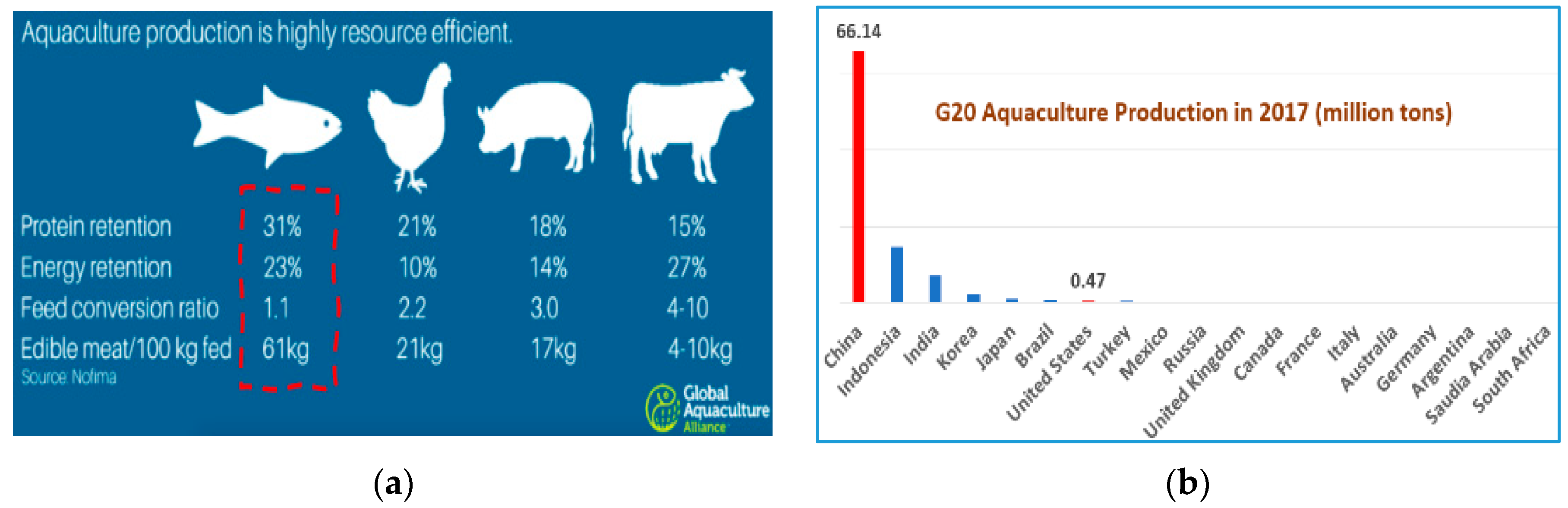
:1. Introduction and Background
Challenges in Aquaculture Farming
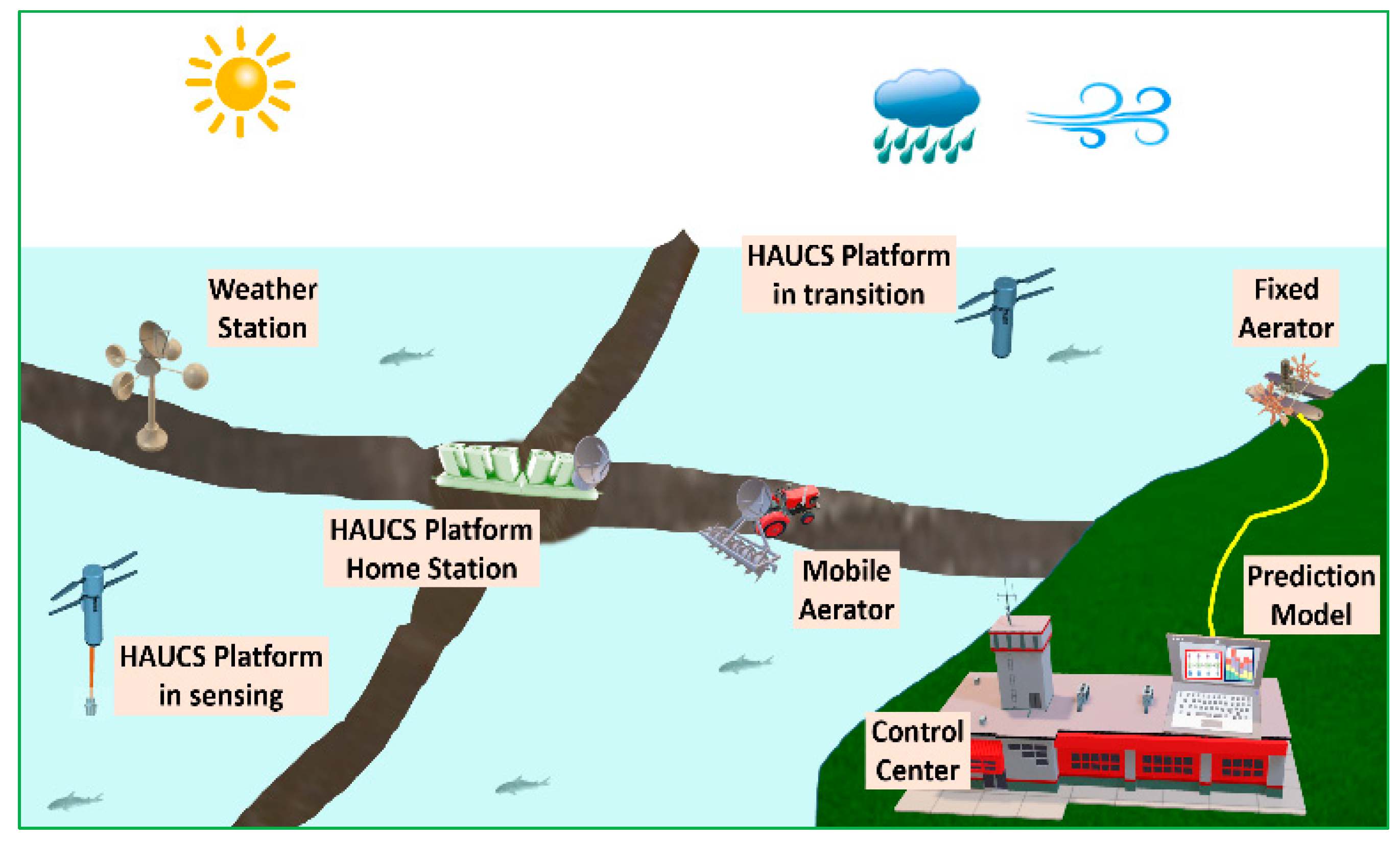
2. Overview of the HAUCS Framework
- Improved scalability—compared with the sensor buoys, HAUCS design can be easily adapted to farms of varying scales.
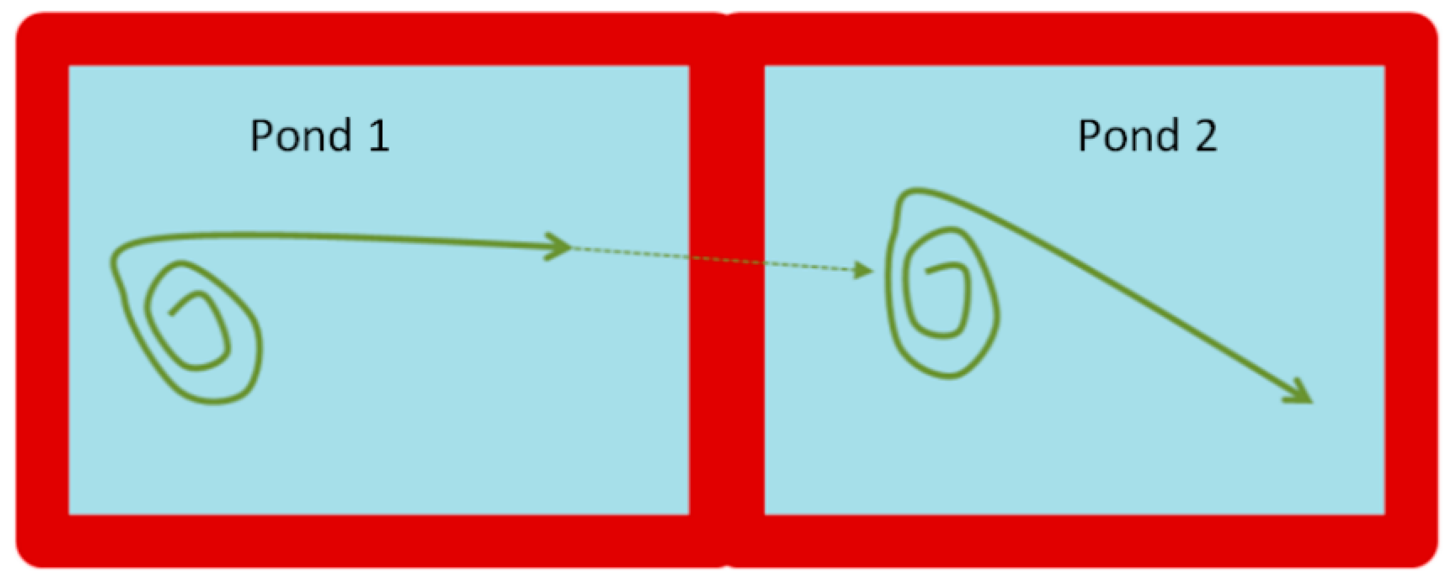
- Broad spatial coverage—capable of realizing novel sensing patterns to cover different areas on a large pond, hence providing more accurate reporting of pond conditions.
- Mitigated biofouling—avoiding sensors in bio-productive water.
- Supporting novel sensing schemes to cover extended spatial regions and generate more robust readings than the traditional truck-based data acquisition.
3. Development and Field Demonstration of Drone-Based HAUCS Sensing Payload
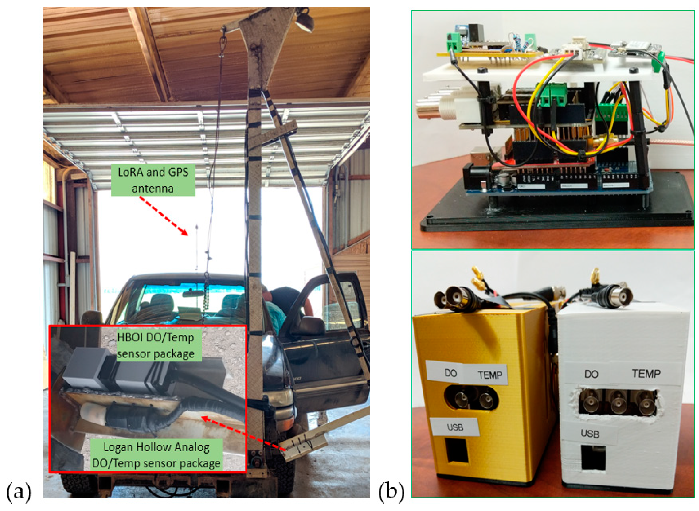
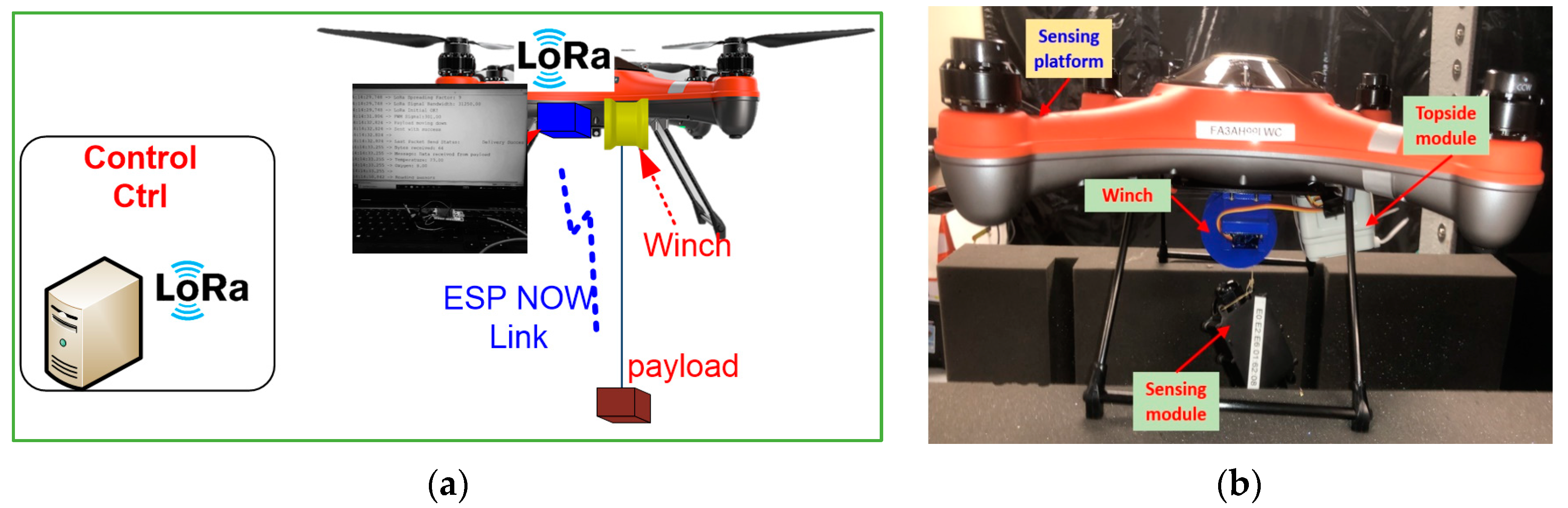
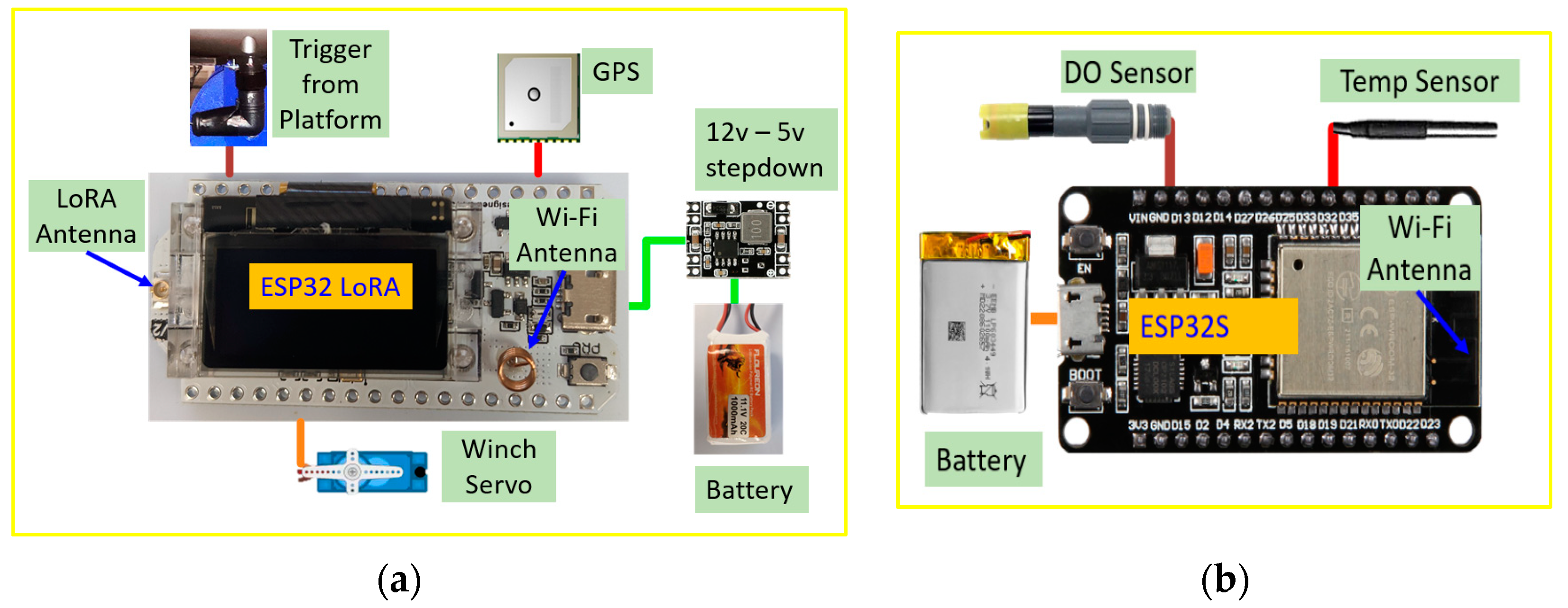
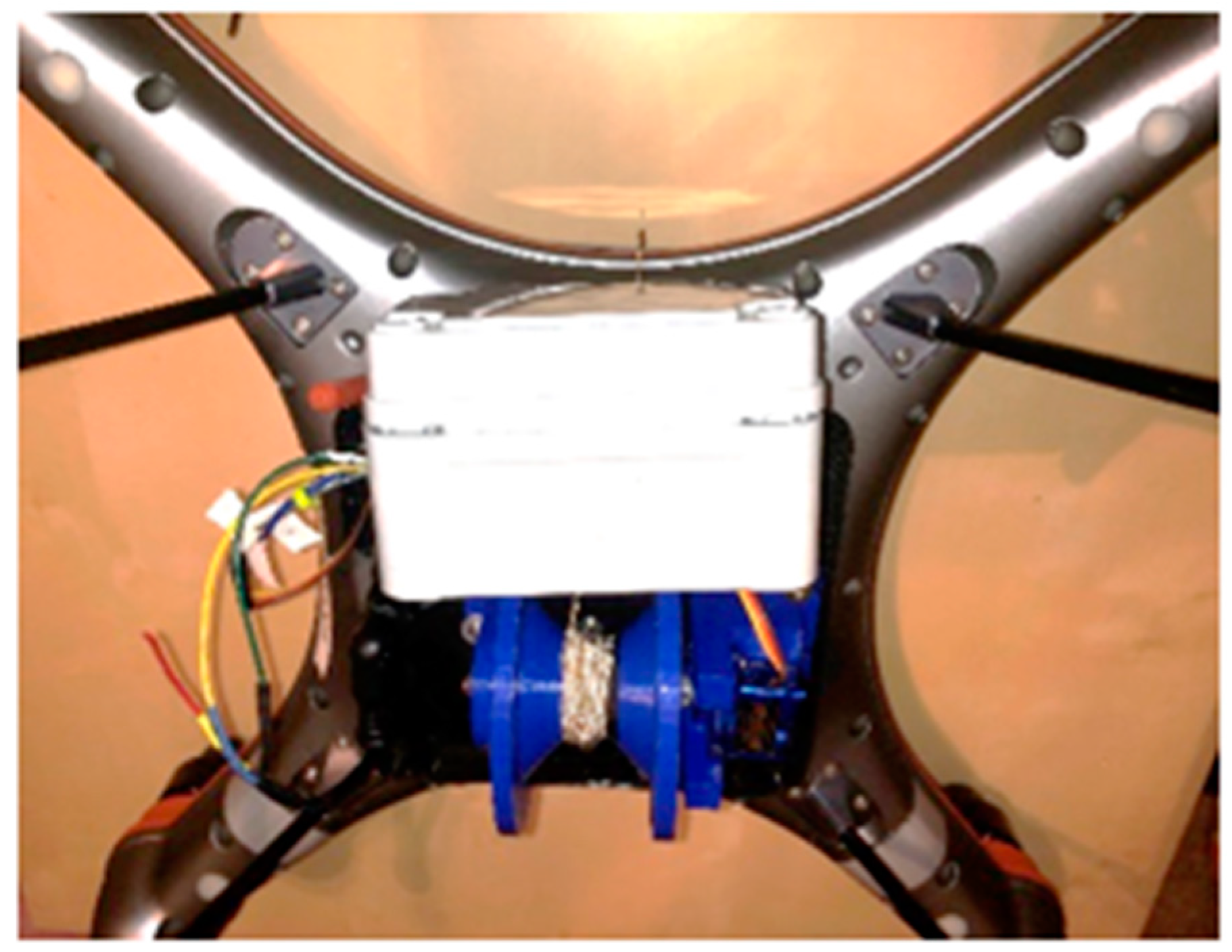
3.1. Development of Drone-Based HAUCS Sensing
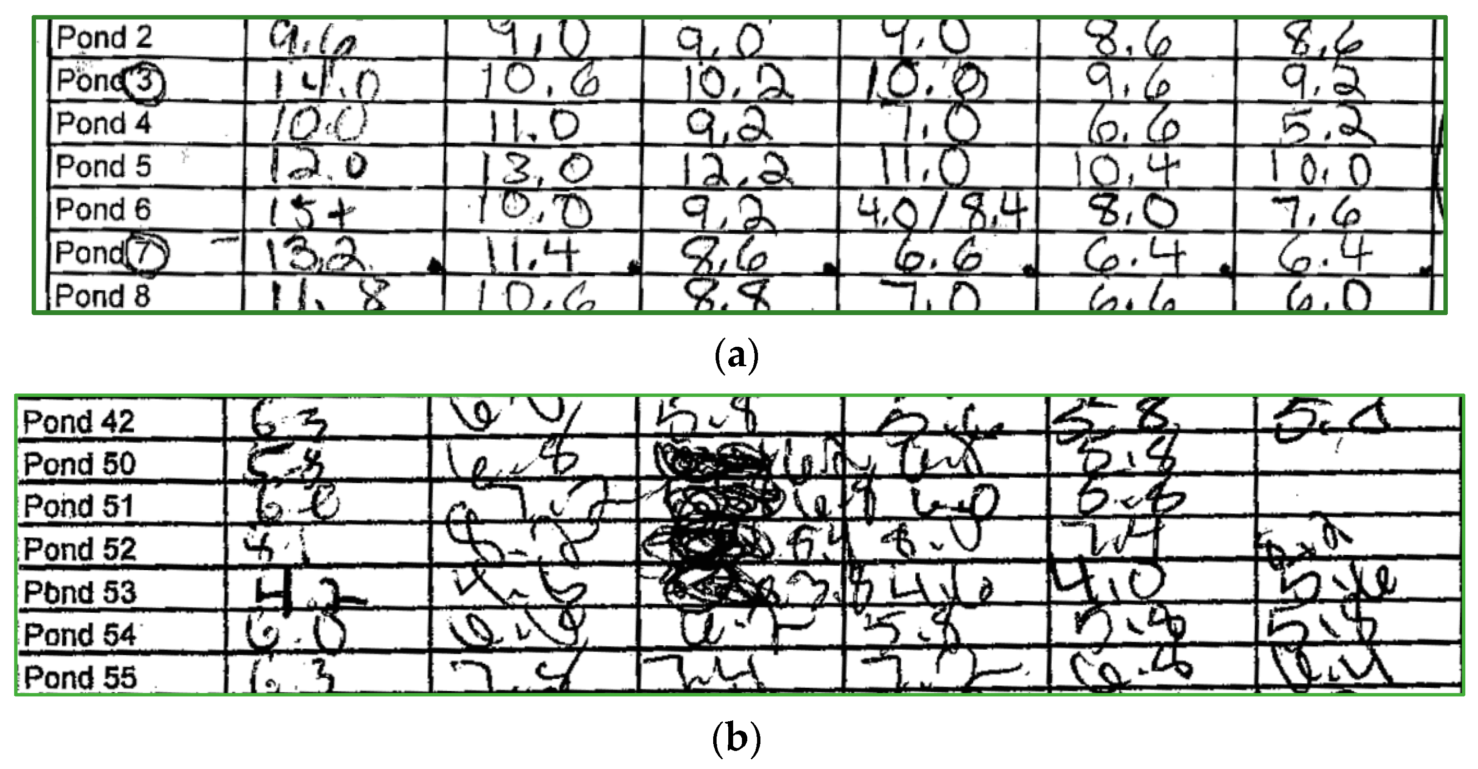
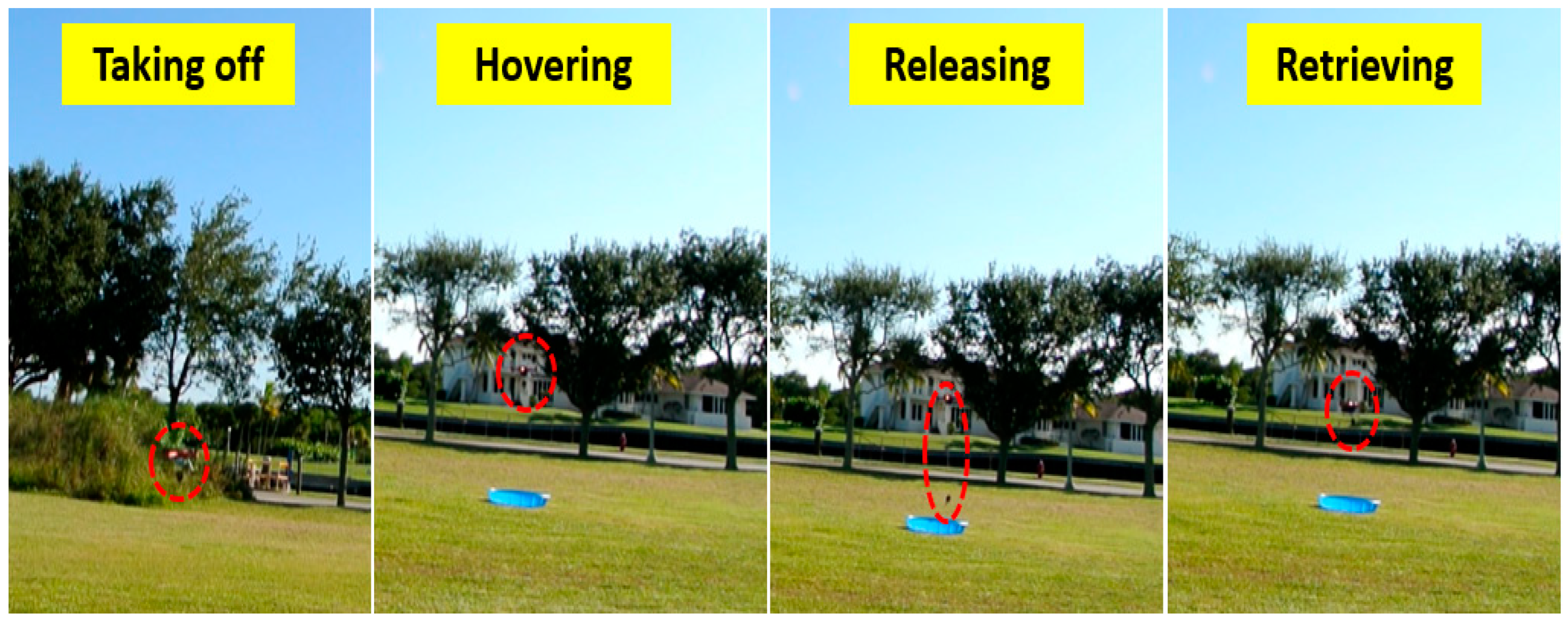
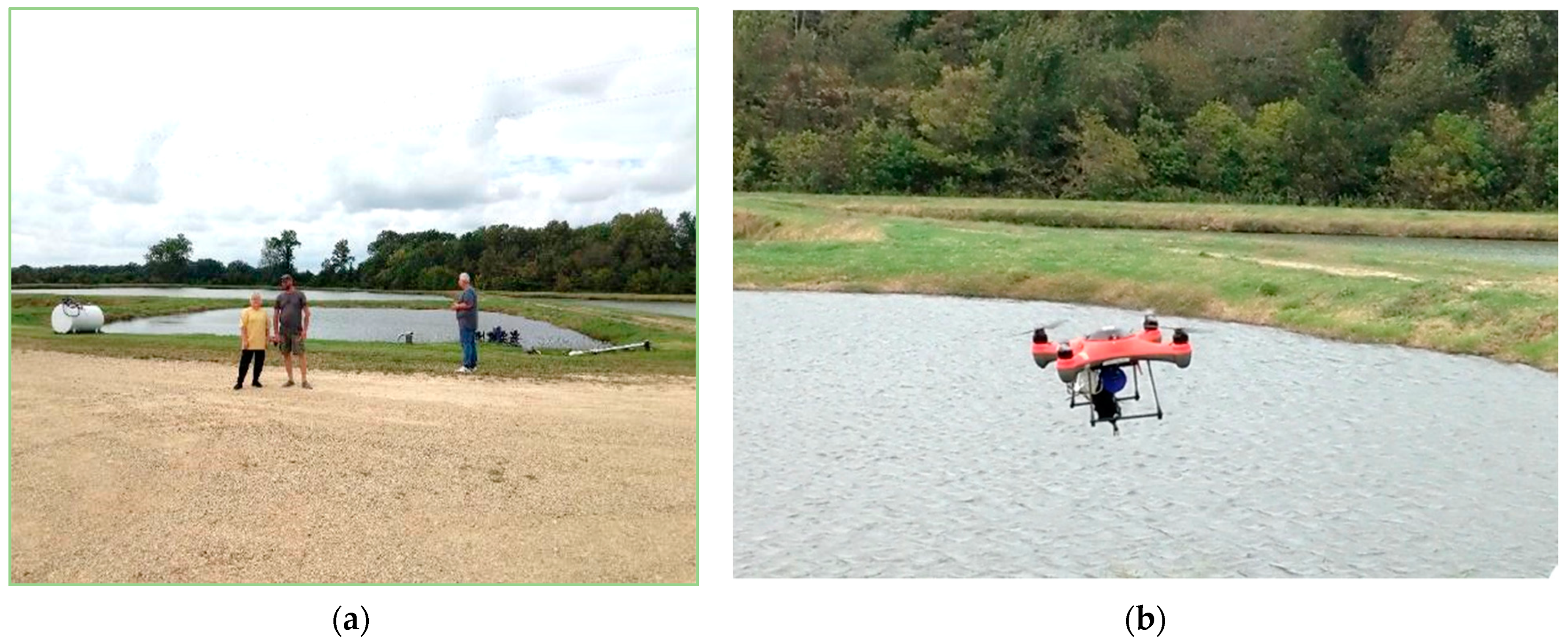
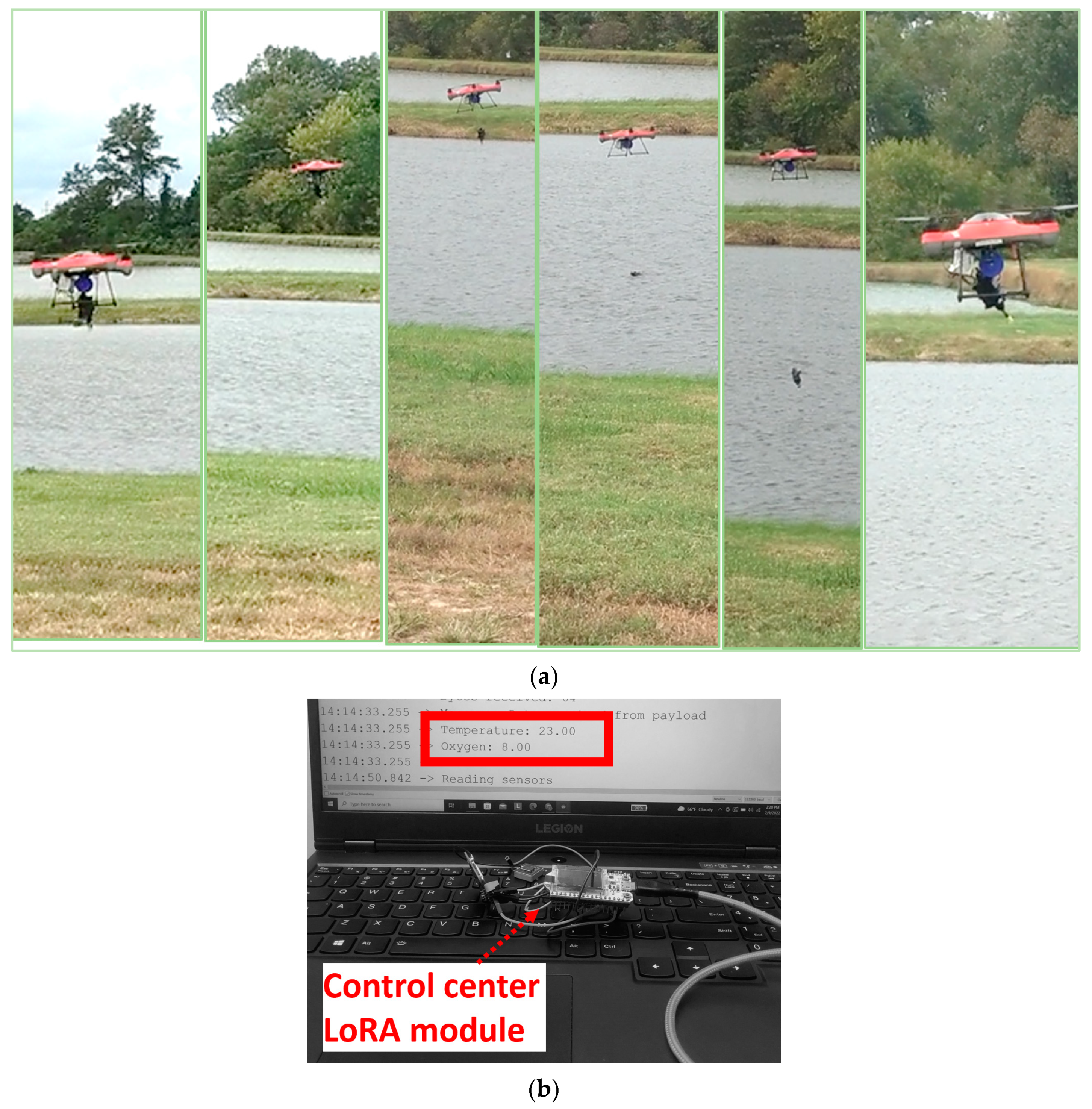
3.2. Lab and Field Deployment
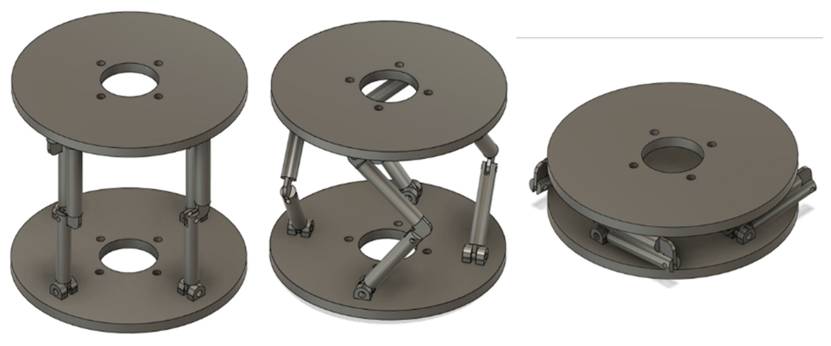
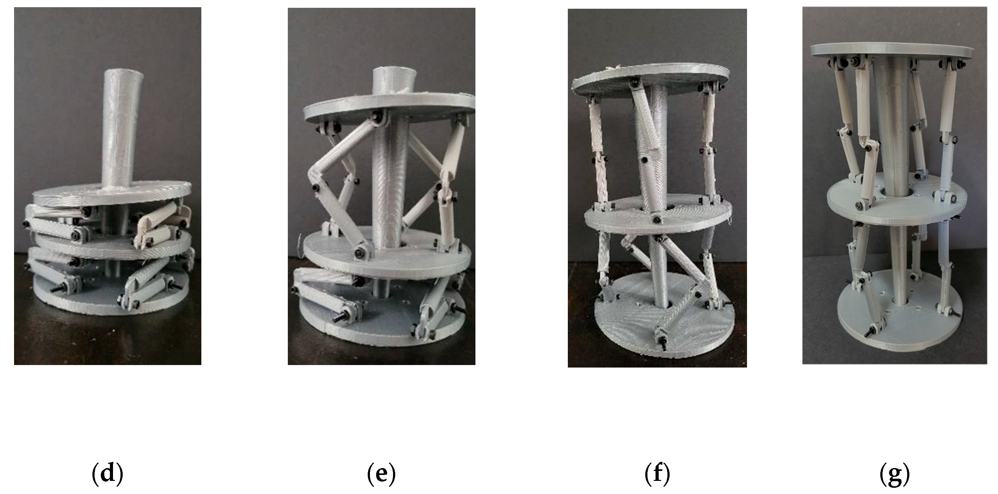
4. Feasibility Study of a Kresling Kirigami Robotic Extension Design
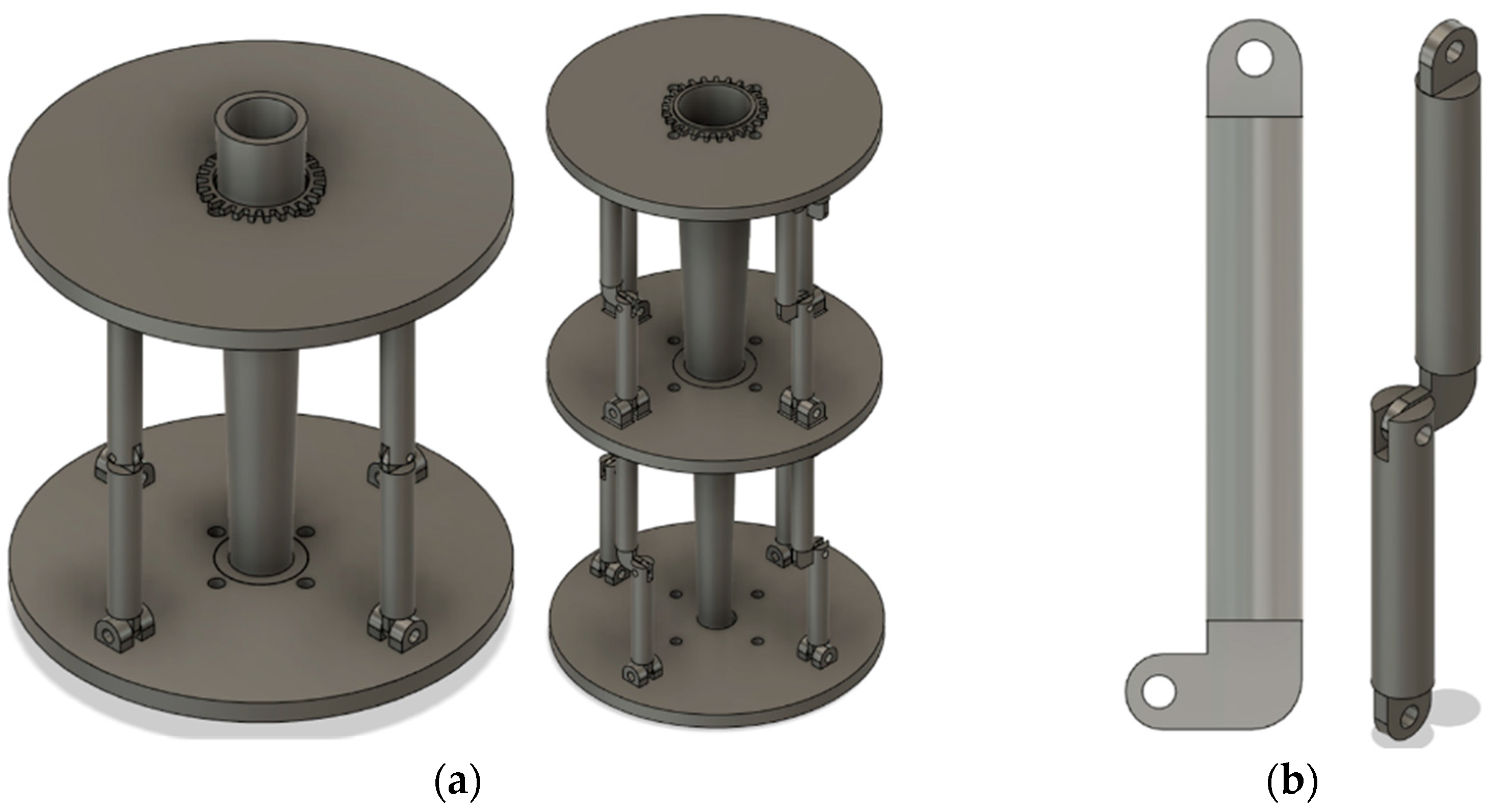
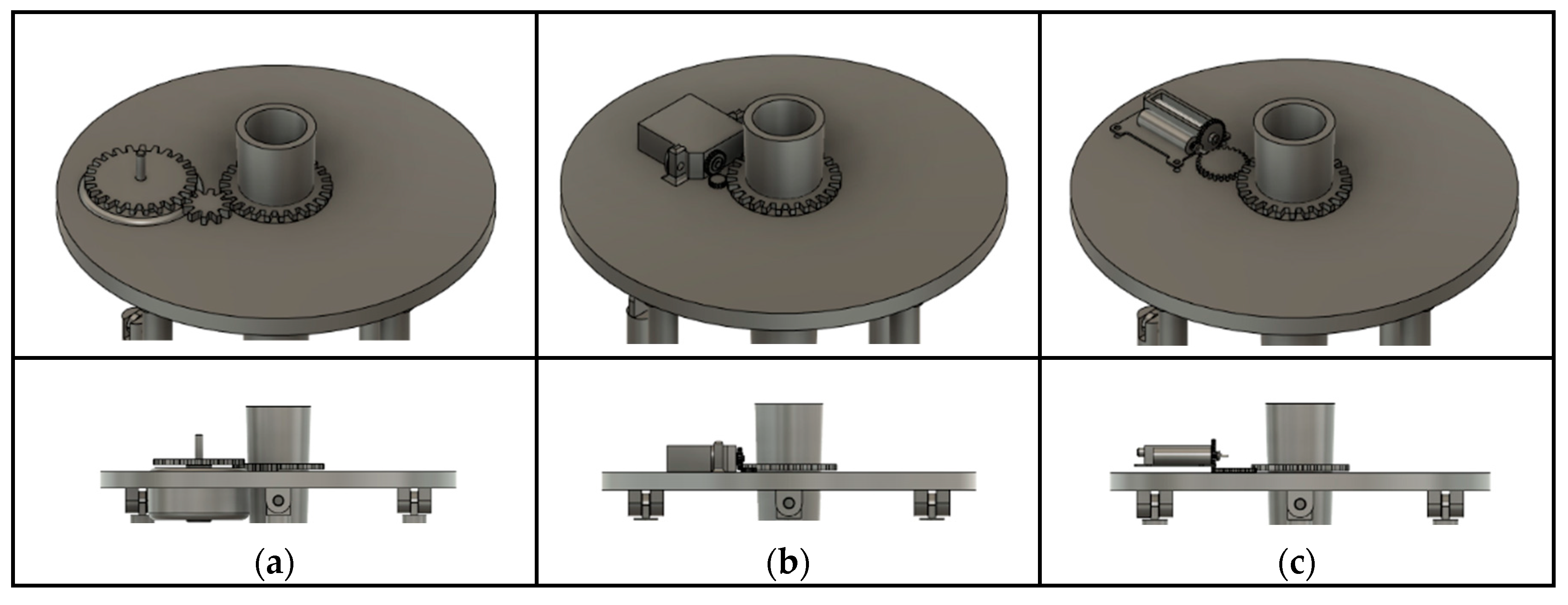
4.1. Kresling Kirigami Prototype Design
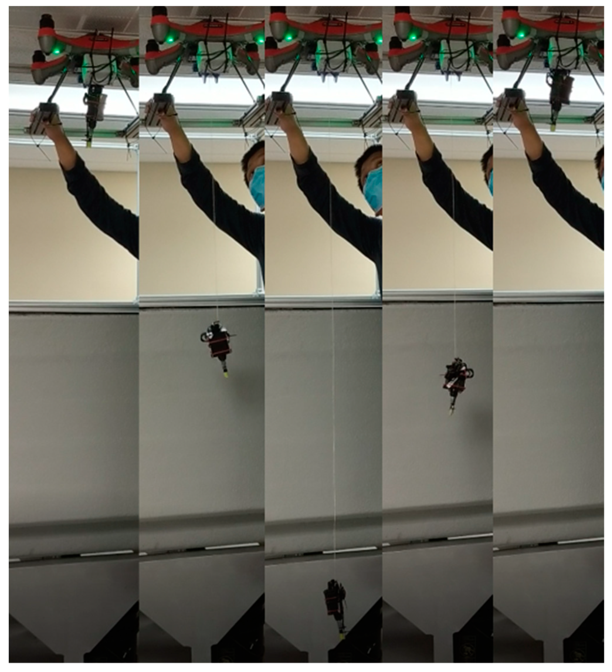
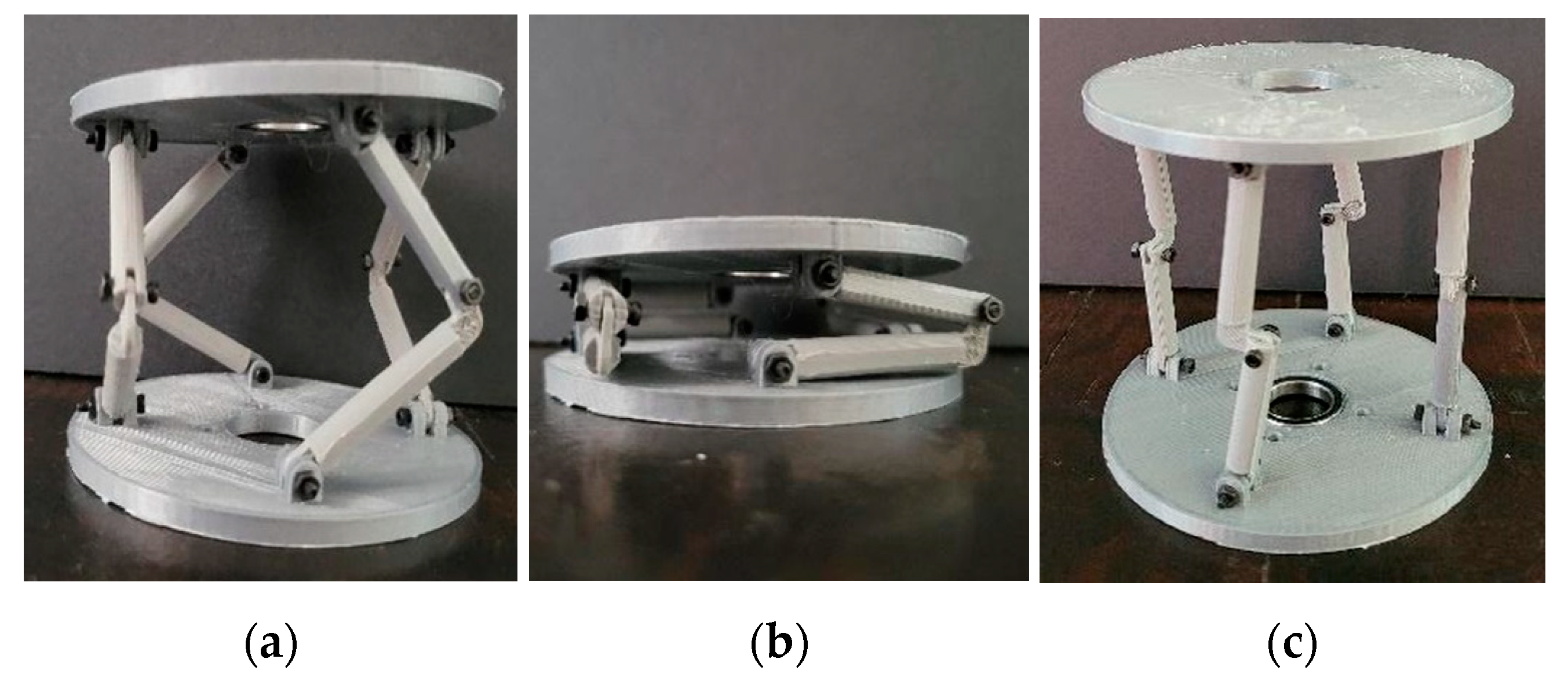
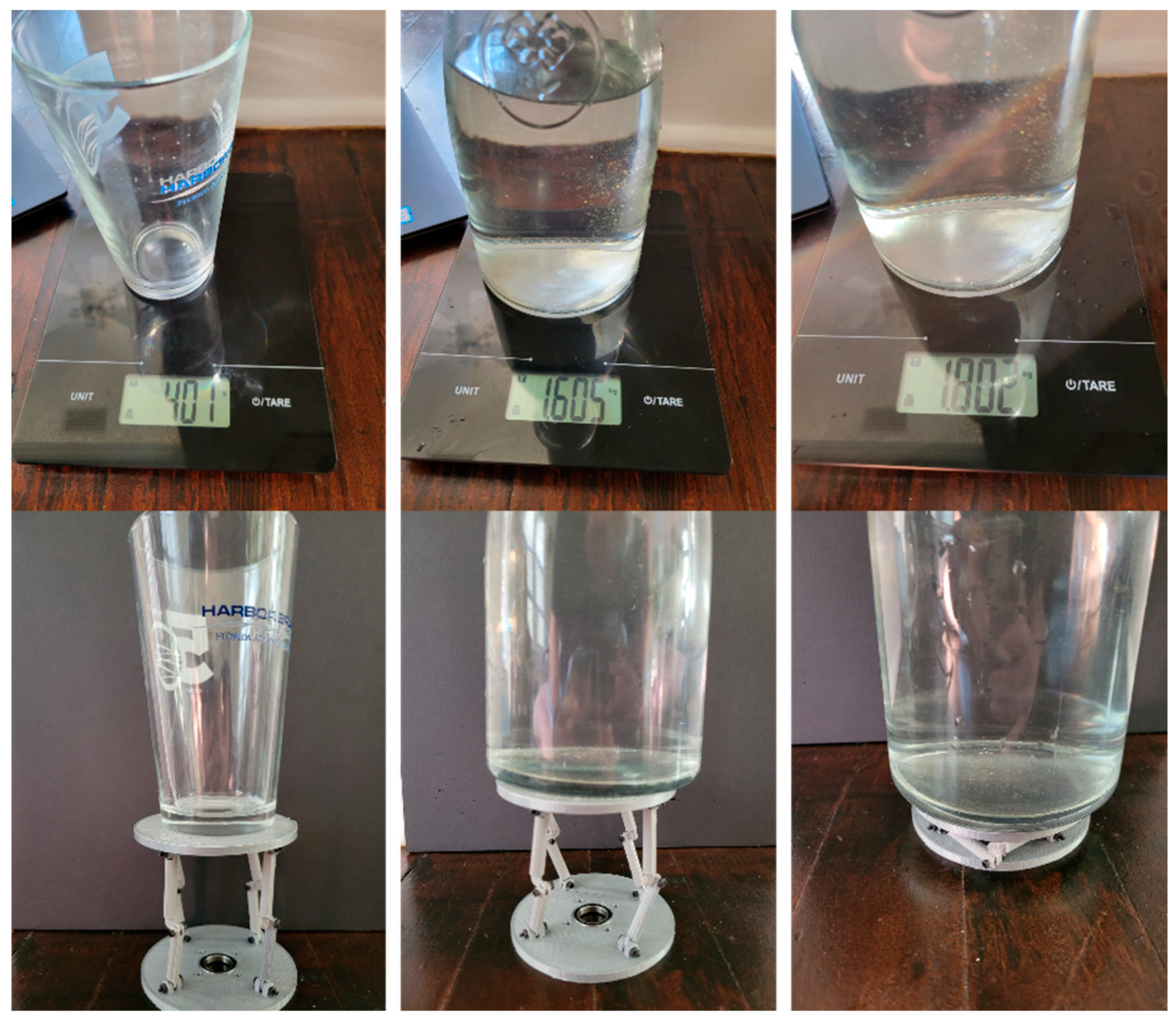
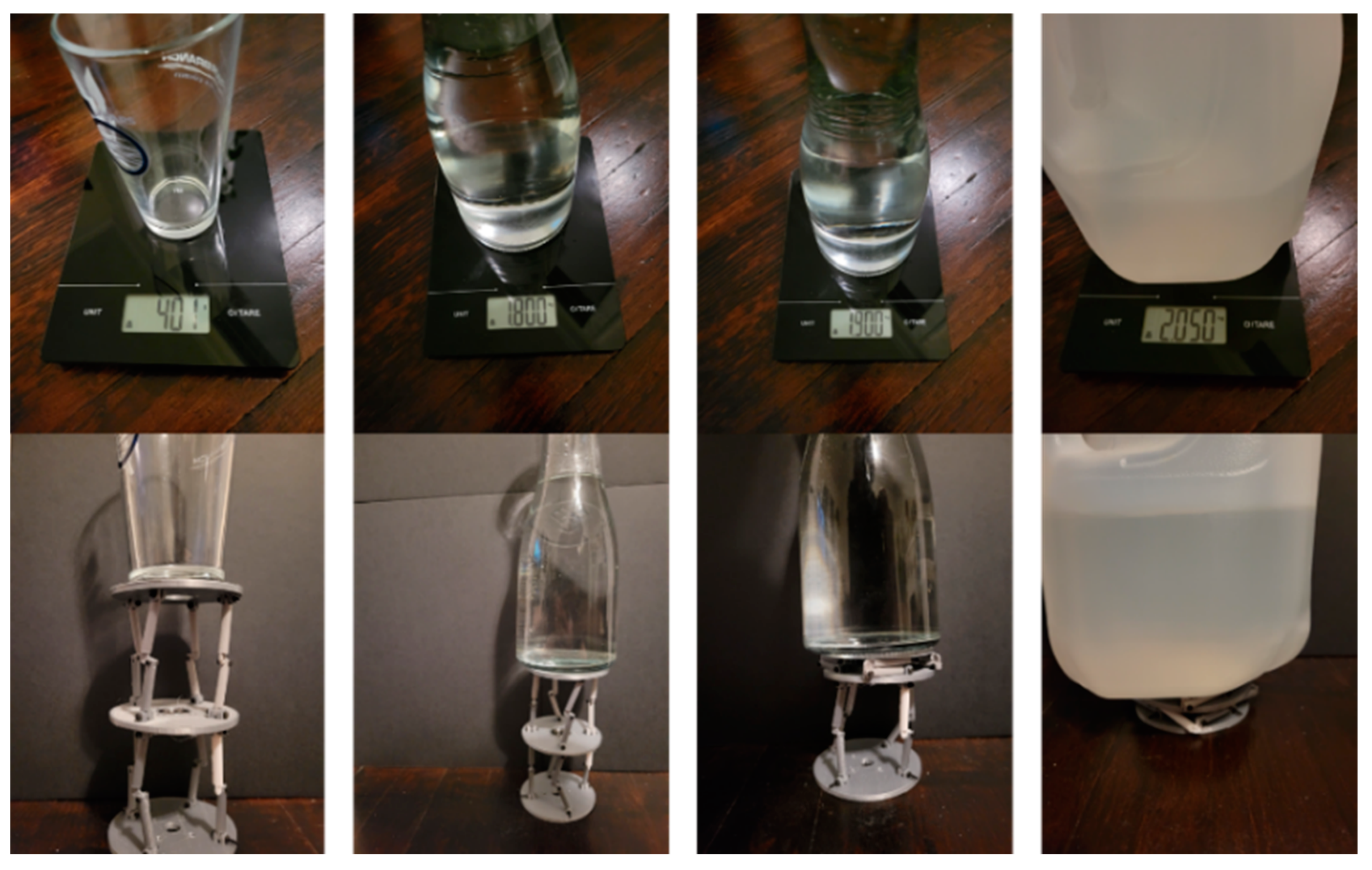
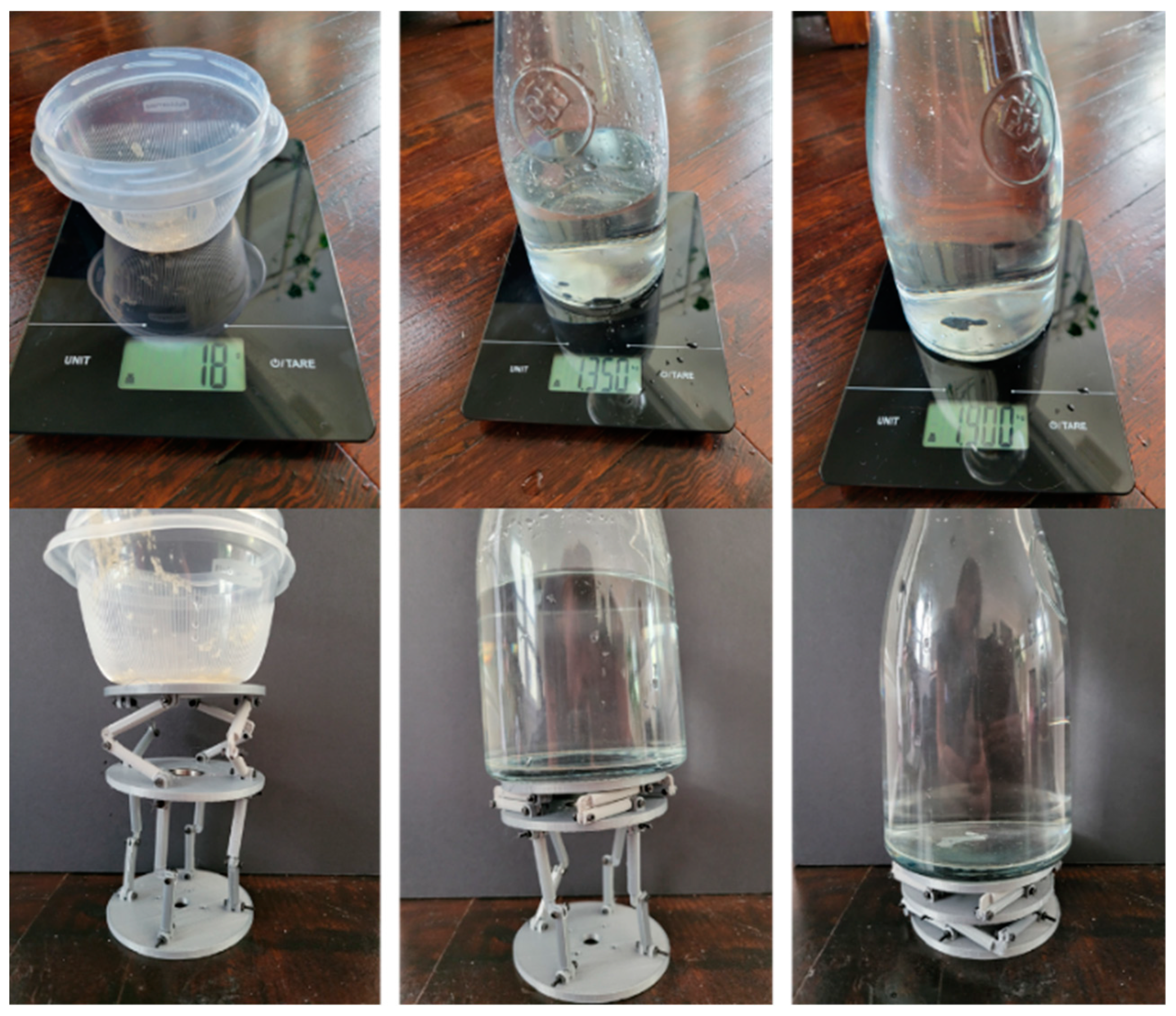
4.2. Laboratory Validations
5. Conclusions
6. Patents
Author Contributions
Funding
Acknowledgments
Conflicts of Interest
References
- Aravind, K.R.; Raja, P.; Pérez-Ruiz, M. Task-based agricultural mobile robots in arable farming: A review. Span. J. Agric. Res. 2017, 15, e02R01. [Google Scholar] [CrossRef]
- Bhandari, S.; Raheja, A.; Green, R.L.; Do, D. Towards collaboration between unmanned aerial and ground vehicles for precision agriculture. In Autonomous Air and Ground Sensing Systems for Agricultural Optimization and Phenotyping II; SPIE: Orlando, FL, USA, 2017; Volume 10218. [Google Scholar]
- Schimmelpfennig, D. Precision Agriculture Technologies and Factors Affecting Their Adoption. 12 May 2016. Available online: https://www.ers.usda.gov/amber-waves/2016/december/precision-agriculture-technologies-and-factors-affecting-their-adoption/ (accessed on 1 February 2018).
- Meola, A. IOT-101: The Essential Guide to the Internet of Things. April 2018. Available online: https://artillry.co/wp-content/uploads/2019/08/Business-Insider-IOT-101.pdf (accessed on 11 August 2020).
- The State of World Fisheries and Aquaculture 2020; Food and Agriculture Organization of the United Nations: Rome, Italy, 2020.
- What Is Aquaculture and Why Do We Need It? Global Aquaculture Alliance. Available online: https://www.aquaculturealliance.org/blog/what-is-aquaculture-why-do-we-need-it/ (accessed on 24 November 2020).
- Yuan, Q.; Song, G.; Fullana-I-Palmer, P.; Semakula, H.; Mekonnen, M.; Zhang, S. Water footprint of feed required by farmed fish in China based on a Monte Carlo-supported von Bertalanffy growth model: A policy implication. J. Clean. Prod. 2017, 153, 41–50. [Google Scholar] [CrossRef]
- Hall, S.; Delaporte, A.; Phillips, M.; Beveridge, M.; O’Keefe, M. Blue Frontiers: Managing the Environmental Costs of Aquaculture; The WorldFish Center: Penang, Malaysia, 2011. [Google Scholar]
- Aquaculture Production (Indicator). OECD. 2020. Available online: https://doi.org/10.1787/d00923d8-en (accessed on 24 November 2020).
- Dureisseix, D. An Overview of Mechanisms and Patterns with Origami. Int. J. Space Struct. 2012, 27, 1–14. [Google Scholar] [CrossRef]
- Lang, R.J. Origami: Complexity increases (again). Eng. Sci. 2004, 67, 5–19. [Google Scholar]
- Zirbel, S.; Magleby, S.; Howell, L.; Lang, R.; Thomson, M. Accommodating thickness in origami-based deployable arrays. J. Mech. Des. 2013, 135, 111005. [Google Scholar] [CrossRef]
- Li, Y.; Liu, W.; Deng, Y.; Hong, W.; Yu, H. Miura-ori enabled stretchable circuit boards. Nat. Partn. J.-Flex. Electron. 2021, 5, 1–9. [Google Scholar] [CrossRef]
- Thrall, A.P.; Quaglia, C.P. Accordion shelters: A historical review of origami-like deployable shelters developed by the US military. Eng. Struct. 2013, 59, 686–692. [Google Scholar] [CrossRef]
- Randall, C.L.; Gultepe, E.; Gracias, D.H. Self-folding devices and materials for biomedical applications. Trends Biotechnol. 2012, 30, 138–146. [Google Scholar] [CrossRef] [Green Version]
- Peraza-Hernandez, E.A.; Hartl, D.J.; Malak, R.J., Jr.; Lagoudas, D.C. Origami-inspired active structures: A synthesis and review. Smart Mater. Struct. 2014, 23, 094001. [Google Scholar] [CrossRef]
- Kresling, B. Plant Design: Mechanical Simulations of Growth Patterns and Bionics. Biomimetics 1995, 3, 105–222. [Google Scholar]
- Guest, S.D.; Pellegrino, S. The Folding of Triangulated Cylinders Part I: Geometric Considerations. ASME J. Appl. Mech. 1994, 61, 773–777. [Google Scholar] [CrossRef]
- Guest, S.D.; Pellegrino, S. The Folding of Triangulated Cylinders Part II: The Folding Process. ASME J. Appl. Mech. 1994, 61, 778–783. [Google Scholar] [CrossRef]
- Guest, S.D.; Pellegrino, S. The Folding of Triangulated Cylinders Part III: Experiments. ASME J. Appl. Mech. 1996, 63, 77–83. [Google Scholar] [CrossRef] [Green Version]
- Kresling, B. Folded Tubes as Compared to Kikko (“Tortoiseshell”) Bamboo. In Origami; AK Peters: Natick, MA, USA, 2001; pp. 197–207. [Google Scholar]
- Hunt, G.W.; Ario, I. Twist buckling and the foldable cylinder: An exercise in origami. Int. J. Non-Linear Mech. 2005, 40, 833–843. [Google Scholar] [CrossRef]
- Nishiyama, Y. Miura Folding: Applying Origami to Space Exploration. Int. J. Pure Appl. Math. 2012, 79, 269–279. [Google Scholar]
- Yoshimura, Y. On the Mechanism of Buckling of a Circular Cylindrical Shell under Axial Compression; NACA: Washington, DC, USA, 1955. [Google Scholar]
- Kresling, B. Origami-structures in natures: Lessons in designing ‘smart’ materials. In Symposium OO—Multiscale Mechanics of Hierarchical Materials; Cambridge University Press: Cambridge, UK, 2012. [Google Scholar]
- Kim, S.J.; Lee, D.Y.; Jung, G.P.; Cho, K.J. An origami-inspired, self-locking robotic arm that can be folded flat. Sci. Robot. 2018, 3, 1–10. [Google Scholar] [CrossRef] [Green Version]
- Miura, K.; Tachi, T. Synthesis of rigid-foldable cylindrical polyhedra. In Gmuend, Austria. Symmetry Art Sci. 2010, 204–213. [Google Scholar]
- Ouyang, B.; Wills, P.S.; Tang, Y.; Hallstrom, J.O.; Su, T.C.; Namuduri, K.; Mukherjee, S.; Rodriguez-Labra, J.I.; Li, Y.; Ouden, C.J. Initial Development of the Hybrid Aerial Underwater Robotic System (HAUCS): Internet of Things (IoT) for Aquaculture Farms. IEEE Internet Things J. 2021, 8, 14013–14027. [Google Scholar] [CrossRef]
- LoRa Alliance. A technical overview of LoRa® and LoRaWAN™. May 2015. Available online: https://lora-alliance.org/sites/default/files/2018-04/what-is-lorawan.pdf (accessed on 25 June 2018).
- Ouyang, B.; Wills, S.P.; Li, Y.; den Ouden, C. Hybrid Aerial Underwater Robotic System (HAUCS): The Initial Instruments Development and Deployment. In Proceedings of the 2020 IEEE 92nd Vehicular Technology Conference (VTC2020-Fall), Victoria, BC, Canada, 18 November–16 December 2020. [Google Scholar]
- SIYI. 2.4G Datalink User Manual. Available online: https://discuss.ardupilot.org/uploads/short-url/sgfUtaqa7P5KZ8r4jRcTUtVpzoW.pdf (accessed on 9 July 2021).
- Heltec. WiFi LoRa 32 (V2). Available online: https://resource.heltec.cn/download/WiFi_LoRa_32/WIFI_LoRa_32_V2.pdf (accessed on 5 April 2021).
- Shenzhen Anxinke Technology. ESP-32SDatasheet. 3 October 2016. Available online: https://www.es.co.th/Schemetic/PDF/ESP32.PDF (accessed on 1 June 2021).
- espressif. ESP-NOW. Available online: https://docs.espressif.com/projects/esp-idf/en/latest/esp32/api-reference/network/esp_now.html (accessed on 1 June 2021).
- Van Manen, T.; Janbaz, S.; Ganjian, M.; Zadpoor, A.A. Kirigami-enabled self-folding origami. Mater. Today 2020, 32, 59–67. [Google Scholar] [CrossRef]
- Reid, A.; Lechenault, F.; Rica, S.; Adda-Bedia, M. Geometry and design of origami bellows with tunable response. Phys. Rev. E 2016, 95, 013002. [Google Scholar] [CrossRef] [Green Version]
- Saito, K.; Tsukahara, A.; Okabe, Y. Designing of self-deploying origami structures using geometrically misaligned crease patterns. R. Soc. 2016, 472, 20150235. [Google Scholar] [CrossRef] [PubMed]
- Sellner, K.G.; Doucette, G.J.; Kirkpatrick, G.J. Harmful algal blooms: Causes, impacts and detection. J. Ind. Microbiol. Biotechnol. 2003, 30, 383–406. [Google Scholar] [CrossRef] [PubMed]
- Mukherjee, S.; Ouyang, B.; Kamesh, N.; Wills, P.S. Multi-Agent Systems (MAS) related data analytics in the Hybrid Aerial Underwater Robotic System (HAUCS). In Big Data III: Learning, Analytics, and Applications; SPIE: Washington, DC, USA, 2021; Volume 11730. [Google Scholar]
- Kresling, B. Natural twist buckling in shells: From the hawkmoth’s bellows to the deployable Kresling-pattern and cylindrical Miura-ori. In Proceedings of the 6th International Conference on Computation of Shell and Spatial Structures, Ithaca, NY, USA, 28–31 May 2008. [Google Scholar]
- Srinvasan, A. Handbook of Precision Agriculture: Principles and Applications; CRC Press: Boca Raton, FL, USA, 2006. [Google Scholar]


| Weight (g) | 401 | 550 | 700 | 1512 | 1605 | 1727 | 1802 |
| Structure |
| Weight (g) | 401 | 701 | 1000 | 1251 | 1654 | 1800 | 1900 | 2050 |
| Structure 1 | ||||||||
| Structure 2 |
| Weight (g) | 18 | 100 | 306 | 506 | 1350 | 1852 | 1900 |
| Structure 1 | |||||||
| Structure 2 |
Publisher’s Note: MDPI stays neutral with regard to jurisdictional claims in published maps and institutional affiliations. |
© 2022 by the authors. Licensee MDPI, Basel, Switzerland. This article is an open access article distributed under the terms and conditions of the Creative Commons Attribution (CC BY) license (https://creativecommons.org/licenses/by/4.0/).
Share and Cite
Den Ouden, C.J.; Wills, P.S.; Lopes, L.; Sanderson, J.; Ouyang, B. Evolution of the Hybrid Aerial Underwater Robotic System (HAUCS) for Aquaculture: Sensor Payload and Extension Development. Vehicles 2022, 4, 390-408. https://doi.org/10.3390/vehicles4020023
Den Ouden CJ, Wills PS, Lopes L, Sanderson J, Ouyang B. Evolution of the Hybrid Aerial Underwater Robotic System (HAUCS) for Aquaculture: Sensor Payload and Extension Development. Vehicles. 2022; 4(2):390-408. https://doi.org/10.3390/vehicles4020023
Chicago/Turabian StyleDen Ouden, Casey J., Paul S. Wills, Lucas Lopes, Joshua Sanderson, and Bing Ouyang. 2022. "Evolution of the Hybrid Aerial Underwater Robotic System (HAUCS) for Aquaculture: Sensor Payload and Extension Development" Vehicles 4, no. 2: 390-408. https://doi.org/10.3390/vehicles4020023