Article

Unusual Phase Behaviour for Organo-Halide Perovskite Nanoparticles Synthesized via Reverse Micelle Templating

1
Department of Physics, Centre for NanoScience Research, Concordia University, Montreal, QC H4B 1R6, Canada
2
Department of Engineering Physics, McMaster University, 1280 Main St. W, Hamilton, ON L8S 4L7, Canada
*
Author to whom correspondence should be addressed.
Chemistry 2023, 5(4), 2490-2512; https://doi.org/10.3390/chemistry5040163
Submission received: 14 September 2023 / Revised: 30 October 2023 / Accepted: 30 October 2023 / Published: 12 November 2023
(This article belongs to the Section Crystallography)

Abstract

:
Micelle templating has emerged as a powerful method to produce monodisperse nanoparticles. Herein, we explore unconventional phase transformations in the synthesis of organo-halide perovskite nanoparticles utilizing reverse micelle templates. We employ diblock-copolymer reverse micelles to fabricate these nanoparticles, which confines ions within micellar nanoreactors, retarding reaction kinetics and facilitating perovskite cage manipulation. The confined micellar environment exerts pressure on both precursors and perovskite crystals formed inside, enabling stable phases not typically observed at room temperature in conventional synthesis. This provides access to perovskite structures that are otherwise challenging to produce. The hydrophobic shell of the micelle also enhances perovskite stability, particularly when combined with anionic exchange approaches or large aromatic cations. This synergy results in long-lasting stable optical properties despite environmental exposure. Reverse micelle templates offer a versatile platform for modulating perovskite structure and behavior across a broad spectrum of perovskite compositions, yielding unique phases with diverse emission characteristics. By manipulating the composition and properties of the reverse micelle template, it is possible to tune the characteristics of the resulting nanoparticles, opening up exciting opportunities for customizing optical properties to suit various applications.

Graphical Abstract

1. Introduction

Since their re-emergence as photoelectronic materials, hybrid organic–inorganic halide perovskites (MHPs) have led to record-breaking achievements in the fields of light-emitting diodes [1,2], photovoltaics [3,4,5], and lasers [6,7,8,9] and have been used in applications as wide-ranging as down converters for enhanced photovoltaic capacity [10,11], photocatalysts for light-to-fuel conversion [12], and ferroelectrics for actuators [13]. Among their useful characteristics are their high optical-absorption coefficients [3,14,15], tunable band gaps [16], high defect tolerance [17], and long charge-carrier lifetimes [18]. Perovskites owe these properties to their flexible cage structure, where the A-site is occupied by a monovalent organic or inorganic cation, such as methylammonium (CH3NH3+) (MA) or cesium (Cs+); the B-site accommodates a divalent inorganic cation such as lead, tin, or germanium; and the X position is occupied by a halide group, which could be chloride (Cl), bromide (Br), or iodide (I) [19].
The framework structure of MHPs provides a broad range of tunable properties but also imposes restrictions on the selection of ion sizes for the A, B, and X sites due to the cage-like architecture. The stability and formation of perovskite structures rely on the dimensions of the cations and anions involved. The stability of the BX6 octahedron that encloses the A-site cation in a perovskite cage is linked to the octahedral factor ( μ ). The octahedral factor ( μ ), expressed as the ratio of the radius of the B-site cation (rB) and the halide counter ion (rX), shown in Equation (1), can be used to approximate the capacity of the BX6 octahedra to the form. The binding of the B-site cation is determined by the ionic size restrictions imposed by the X6 octahedra. When the octahedral factor  μ  falls within the range of 0.442 to 0.895, the MHP configuration is likely to form [20,21].
μ = r B r X
The Goldschmidt tolerance factor (t) is an empirical index for accessible phases, calculated using the ratio of ionic radii of the constituent A, B, and X ions (rA, rB, and rX), as described by Equation (2) [22]. For an ideal optically active perovskite phase, the tolerance factor range should generally lie between 0.8 and 1.0 [20,21,23,24].
t = r A + r X 2 ( r B + r X )
When the tolerance factor ranges from 0.9 to 1.0, an optically active perovskite with a cubic structure is formed [23,24]. On the other hand, when the tolerance coefficient lies within the range of 0.80 to 0.89, a distorted perovskite structure with an orthorhombic, tetragonal, or rhombohedral (in order of formability) crystal structure is more likely to emerge. A tolerance factor less than 0.8 indicates that the A-site cation is too small to form an optically active MHP phase [9,21]. Furthermore, if the A-site ion is too large, it may produce an optically inactive hexagonal phase with a tolerance factor greater than 1.0 [21] or induce a phase change [25]. Hence, the size of the A-site ion must lie within the range of approximately 155 pm to 260 pm, as illustrated in Figure 1, imposing a constraint on the size of the A-site ion [9,21]. However, if the fabrication methods and conditions are varied, the resulting structure of the formed perovskite may be able to accommodate ions that fall slightly outside of these tolerances due to a rotation of the BX 6  octahedron [25,26,27,28,29].
Yet perovskites are still very sensitive to the size of their A-site cations, which can lead to the reorganization of their cage structures by altering the dimensions [25,30,31]. For example, a larger A-site cation can lead to the formation of 2D A2BX4-type MHP, consisting of a mono-molecular layer of BX6 octahedrals separated by A-site cation barrier layers, a 1D A3BX5-type chain-like structure, or a A4BX6-type 0D structure [20,25]. Due to their soft ionic nature, strain in the cage structure can occur when different cations are added, which can be used to engineer the band gap and cage stability [32,33,34]. A compressive strain typically produces a red shift in absorbance and emission with a narrower band gap, while a tensile strain results in a blueshift with a wider band gap [33]. According to computational studies, the band gap range of CsPbI3 perovskite can be tuned between 1.03 eV and 2.14 eV by adjusting the strain from −5% to 5% [35].
Due to the versatility of ionic substitutions that are possible without disrupting the perovskite crystal structure, the fine tuning of the properties to match a particular application is relatively straightforward [27]. Such substitutions of the A, B, and X site ions have been used to engineer the band gap, improve material stability, and improve photoluminescence quantum yields (PLQYs) [9,36]. For bulk halide perovskite synthesis, the ideal method of obtaining the desired band gap is by adding the raw precursor in extremely precise stoichiometric ratios; however, this can be complicated by the extremely fast reaction kinetics, making some structures inaccessible [37,38]. Low-dimensional perovskites, which include quantum dots (QDs) and nanoparticles, offer additional degrees of freedom over the bulk to tune the optoelectronic properties and control the synthesis process [39]. Based on the synthesis conditions, a wide range of nanostructures can be obtained due to controllable crystallization [18,40]. Perovskite nanoparticles have been reported to possess better photoluminescence (PL) properties than bulk perovskites and conventional semiconductors nanoparticles such as high PLQY [9,41], fine-band-gap tunability [41,42,43], and higher photoluminescence lifetimes due to the predominance of shallow trap states rather than non-radiative deep traps [17].
The compositional and structural engineering of MHPs has greatly improved their performance, yet a few hurdles still need to be addressed for widespread commercialization. The fast reaction kinetics involved in halide perovskite formation can limit the tailored compositions [16,44,45], leading to defects and phase instability. Desirable phase structures are sometimes not achievable without post-processing or additives to tune the structure [46,47]. Such modifications unfortunately tend to introduce greater defects due to re-crystallization [48], increase the potential for phase separation [49], or reduce photon absorption due to unintended changes in the band gap [50].
In this contribution, we discuss the unusual phase behaviour that occurs in situ when organo-halide perovskites are synthesized using reverse micelle templates. We fabricated our nanoparticles by leveraging the properties of diblock-copolymer reverse micelles [51] to achieve nanoparticle structures that are challenging to achieve at room temperature or not observed in bulk phases. Moreover, our nanoreactors slow down the reaction kinetics of nanoparticle formation, resulting in high uniformity and a thermodynamically stable stoichiometry while simultaneously increasing the stability of the particles with exposure to ambient conditions.

2. Materials and Methods

Perovskite nanoparticles were produced through a two-step loading process into poly(styrene-b-2-vinyl pyridine) diblock copolymer (Polymer Source) reverse micelles, as described previously [10,26]. Reverse micelles were prepared by dissolving poly(styrene-b-2-vinyl pyridine) di-block copolymers in reagent grade non-polar o-xylene, with a concentration of 3 g/L under continuous stirring. A measure of 0.5 M precursor solutions were made by adding organic salts (methylammonium iodide (MAI, Greatcell Solar), formamidinium iodide (FAI, Greatcell Solar), or pyrrolidinium iodide (PyI, Sigma-Aldrich) to isopropanol (IPA) (Caledon, reagent grade), and the inorganic salts (lead(II) iodide (PbI2)(Alfa Aesar, 99.9985%) or lead(II) bromide (PbBr2, Sigma-Aldrich 99.99%) to N,N-Dimethylformamide (DMF) (Sigma Aldrich, 99.8%). After confirmation of the formation of reverse micelles with atomic force microscopy (AFM), the precursor salts were added sequentially, with 24 h loading steps between precursor additions to allow the infiltration of each precursor. For iodide-based perovskites, an organic iodide precursor solution was followed by the PbI solution; for bromide-based or mixed halide-phase nanoparticles, a stoichiometric amount of PbBr2 was added after the organic iodide precursor. After loading both salts, the loaded reverse micelles solution was centrifuged to remove excess, non-infiltrated salt and stirred further to prevent coagulation. Where indicated, the polymer micelle was removed using O 2  plasma etching (Harrick Plasma, Ithaca, US PDC-001, 29.6 W, 25 min) after spin coating on cleaned silicon substrates.
Atomic force microscopy (Asylum MFP-3D, Oxford Instruments, Etobicoke, Canada) was performed using probes with a spring constant of 2.8 N/m and resonant frequency at 75 kHz (Nanotools, Henderson, US, EBD-FMR) in tapping mode in an ambient environment for spin-coated samples on undoped silicon substrates. WSxM 5.0 was used for AFM image processing. Photoluminescence (PL) measurements used an 11 mW, 405 nm diode laser (spot diameter 1–2 mm). Sample emission was fibre-coupled through a long-pass filter into a monochromator (Andor, Oxford Instruments, Concord, US, Shamrock 303i, grating 500 nm blaze, 150 lines/mm), and detected with an ICCD (Andor, Oxford Instruments, Concord, US, iStar A-DH320T-18U-73). The sample was focused with a 60× objective, and the laser power was adjusted to 33% to avoid laser bleaching, with an exposure time of 5 s and a slit opening of 0.02 mm. The detection range was from 450 to 960 nm. Both the corners and the centre of the spin-coated sample were examined, as more material tends to be flushed to the corners during the process of spin coating. The measurement was taken in a darkened environment to prevent stray light. UV-Vis spectroscopy (PerkinElmer, Woodbridge, Canada, Lambda 35) was performed on 0.1 mg/mL loaded micelle solutions, using o-xylene as a dispersant, measured in a 1 × 1 cm quartz cuvette. Normal Raman spectroscopy was performed with a Renishaw inVia spectrometer (Renishaw, Toronto, Canada). All measurements were illuminated with 633 nm laser excitation. The laser power was set to 10 mW, and an objective of 20× and 1800 lines per mm grating was used.
Transmission electron microscopy (TEM) samples were spin-coated on Si3N4 membrane window TEM grid (Norcada) inside a glovebox at 2000 rpm for 45 s (Specialty Coating G3P, Indianapolis, US) and etched under O2 plasma for 25 min (Harrick Plasma, Ithaca, US). JEOL 2010F TEM imaging was operated at 200 kV accelerating voltage with the field emission gun (FEG) source. The scanning transmission electron microscopy (STEM) data collected were analyzed with Gatan Microscopy Suite 3 software.
Samples for X-ray diffraction were prepared by drop-casting 12 drops, each of 4  μ L, on undoped silicon substrates. X-ray diffraction was performed using CuK α 1  ( λ  = 1.54 Å) or Co K α  radiation ( λ  = 1.79 Å). The powder diffraction simulation function on Vesta was used to generate .cif files for structures where no powder diffraction file data exists.

3. Results

Using PS-b-P2VP diblock copolymer micelle templates, we have developed a recipe for producing ordered MHPs with a low polydispersity index (PDI) at room temperature, as described in our previous reports [10,26]. We have found that micelle-templated nanoparticles have better surface coverage and a longer photoluminescence lifetime than nanoparticles made using methods such as ligand-assisted synthesis [10,33]. Due to the separated loading steps, we are able to control the reaction kinetics, allowing better tunability over doping or ionic substitution [10]. We have therefore implemented this approach, as shown schematically in Figure 2, to produce a variety of MHP nanoparticles. Though we mostly discuss the synthesis of perovskites with a single halogen in this contribution to highlight the unusual phases that micelle templating makes available, it is also possible to produce mixed halides with emission across the visible spectrum through careful control of the synthesis parameters [52].
As the reaction region to form the nanoparticles is limited to the spaces within the micelles, size-tunable nanoparticles with PDIs around 0.10 are easily achieved [10,26,53,54]. Such values are within the range of monodispersity [55,56], which is a key metric for the widescale application of nanoparticle-based devices [57]. As many losses in perovskite devices result from inhomogeneous films and interfaces [58,59,60], highly uniform monodispersed structures can lead to higher performance devices. These nanoparticles self-assemble into organized arrays, with a high degree of hexagonal ordering, as shown in Figure 3, with photoelectron quantum yields between 40–70% for these submonolayer films. Note that all samples have had the polymer shell removed to show the true size of the nanoparticles (a comparison of micelle-encapsulated nanoparticles before and after polymer removal is shown in Figure S1). In addition to the benefit of enhanced homogeneity, the use of the micelle template provides access to unusual phases that are typically difficult to achieve at room temperature, or have not been reported before, for various MHPs.

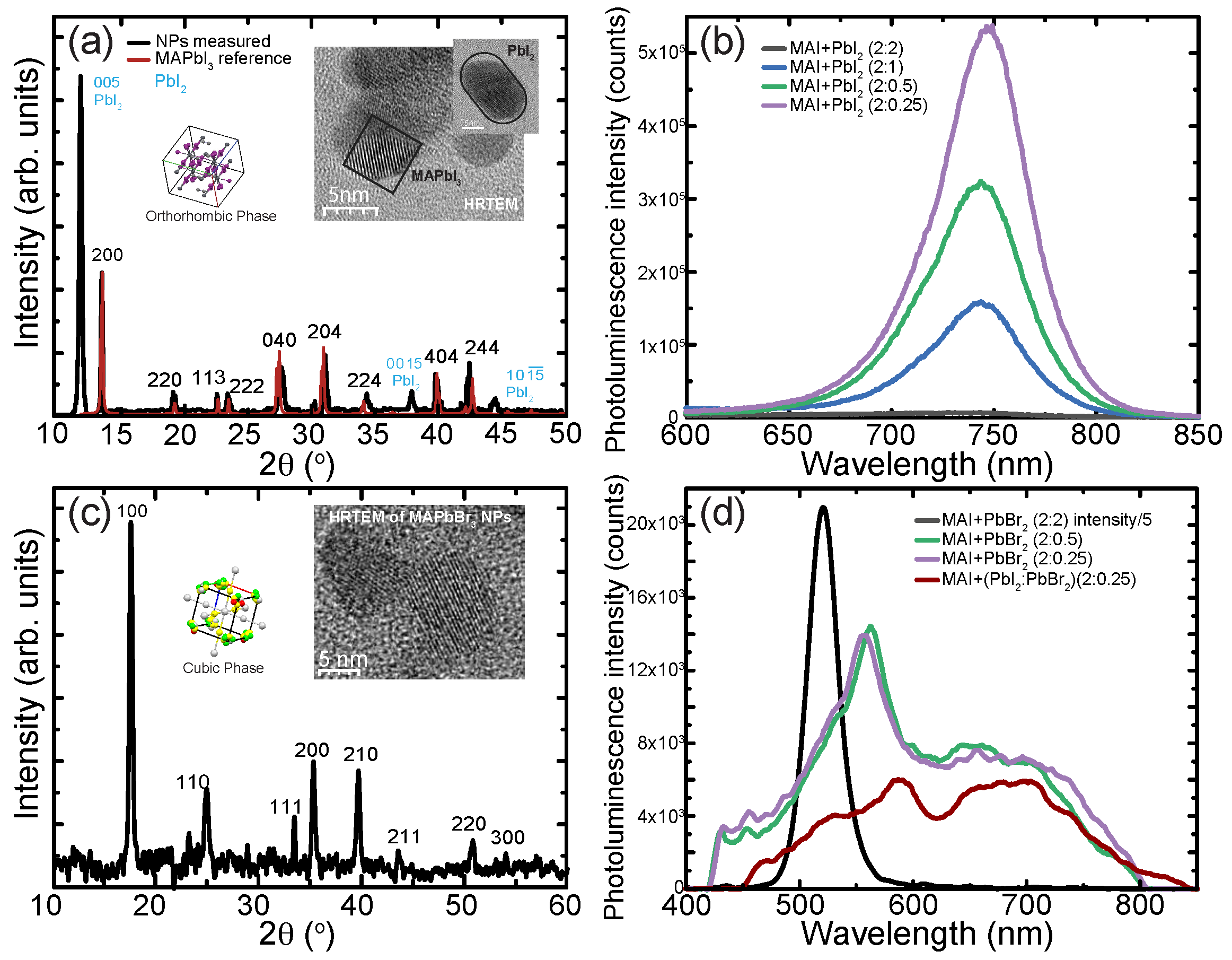
Methylammonium-Based Perovskite Nanoparticles

Due to their small size, methylammonium ions were considered the first and most suitable organic cation for MHP [61], and they quickly became the prototypical MHP after their re-introduction in solar cell devices [62,63,64]. Due to its high optical absorption coefficients [65,66], optimal band gaps [65,67], and long charge carrier lifetimes and diffusion lengths [18,68], MAPbI3 has revolutionized photovoltaics, with an exponential increase in power conversion efficiencies from 3.8% in 2009 [62] to over 21% efficiency by 2019 for single crystalline MAPbI3 [69]. The Goldschmidt tolerance and octahedral factors for MAPbI3 are well within the boundaries, allowing for the doping or alloying at each of the three sites, which has resulted in a range of structurally viable materials through multiple-cation, metal-substitution, and halide-engineering approaches [70]. Though bulk films and single crystals are easily achievable, the synthesis of CH3NH3PbI3 (MAPbI3) nanoparticles with controlled size dispersion has proven to be challenging due to their lower stability and sensitivity to moisture [71,72]. Additionally, ligand-assisted synthesis has a tendency to form 1D nanowire structures [8,73,74] or 2D nanoplatelets [16,75,76] rather than true 0D nanoparticles. Using RMD, however, we are able to form highly uniform and emissive arrays of MAPbI3 nanoparticles (see Figure 3b), with PL-emission emission peak at 743 nm (FWHM of 57 nm) and photoluminescence quantum yield of around 45% (see Figure 3q).
X-ray diffraction (XRD) and transmission electron microscopy (TEM) analysis, Figure 4a, indicates that the particles are crystalline, with visible lattice planes in good agreement with the orthorhombic crystalline  α -phase (252413-ICSD) of MAPbI3. The reflections visible at the corresponding  2 θ  values for 2 0 0, 2 2 0, 1 1 3, 2 2 2, 0 4 0, 2 0 4, 2 2 4, 2 4 4, and 0 2 6 hkl planes (see Table 1) are consistent with the orthorhombic  α -phase for MAPbI3 also shown in the figure. Lattice constants extracted are  a = 12.503  Å,  b = 12.493  Å and  c = 12.618  Å, which is also consistent with the orthorhombic phase [77,78,79]. The orthorhombic phase is typically only observed and stable at temperatures below 160K, and usually converts into the cubic phase at higher temperatures [77,78,79]. However, due to micelle templating, we were able to obtain the orthorhombic phase of MAPbI3 at room temperature with high luminescence.
The reflections detected at  2 θ  = 12.64°, 25.90°, and 38.69° also show the presence of PbI2 in the hexagonal phase, which was confirmed with the powder diffraction card 23762-ICSD [80], as shown in Table 1. Though there are features at 22.5° and 24.8° that could be assigned to PbI2, these are typically expected to have relative intensities less than 10%. Given that the observed intensity of these features is higher and more in line with MAPbI3, they were not assigned to the PbI2 phase.
As PbI2 was used as the second precursor for the synthesis of MAPbI3 in the micelles, the presence of PbI2 suggests that there was excess of unreacted precursors in the solution, rather than a decomposition of the perovskite, as the nanoparticles themselves are highly stable due to the polymeric shielding [52,81]. Additionally, as XRD requires a large amount of material to achieve an adequate signal, the micelles had to be drop-cast onto the substrate, potentially resulting in trapped residual precursors that would normally be removed during spin coating. TEM measurements confirm the presence of large impurities, which show an approximate size of 13.5 nm, from unreacted PbI2 shown in the inset of Figure 4a. These particles have an ellipsoid shape, rather than the spherical perovskite nanoparticles of ∼6.5 nm that were produced inside the reverse micelle nanoreactors. We decreased the amount of PbI2 added to the solution relative to the MAI, and as Figure 4b shows, the emission intensity increased by over 10× as the relative amount of PbI2 added to the solution was decreased (see Supporting Information Figure S2), without changing the size of the nanoparticles (see Supporting Information Figure S3). This confirms that some added PbI2 did not infiltrate the micelles, as the nanoparticle size is typically correlated with the amount of salt infiltration [82]. Additionally, the strong affinity of lead to 2VP would have resulted in the unravelling of the micelle due to unreacted PbI2 inside the micelle [10,26], destroying nanoparticle formation. As the nanoparticles were formed with approximately the same size, it is likely that excess PbI2 remained in the colloidal suspension outside the micelles and also poisoned the emission characteristics. This was unique to MAPbI3, however, as we did not observe the same behaviour for MAPbBr3 nanoparticles with decreasing amounts of PbBr2 addition; rather, in that case below, the stoichiometric limit of the two precursors, the perovskite phase barely formed, as evidenced by the weak broadened emission shown in Figure 4d. The XRD diffractogram in Figure 4c also shows no evidence of PbBr2.
MAPbBr3 is an interesting case itself, as, although iodine-based perovskite synthesis was relatively straightforward utilizing MAI and PbI2 loaded sequentially, it is difficult to produce uniform nanoparticles from the conventional approach, a mixture of MABr and lead bromide (PbBr2), in the reverse micelles [10]. Due to the densely packed nature of the micelle core [83], the MABr ion fails to infiltrate micelles with higher molecular weight polymers [10]; as a result, the micelle core unravels on the introduction of the lead salt [10] due to the strong affinity between Pb and 2VP units [26]. Non-uniform particles can be produced by using low-molecular-weight co-polymers to form the micelles, which form a balloon shape that allows the infiltration of the MABr molecule [10,26,83].
As the micelle templating approach separates the precursors and kinetically limits the reaction, we were able to use another approach that takes advantage of the properties of the reverse micelles themselves to produce uniform MAPbBr3 nanoparticles. The addition of iodine is known to stabilize micelles by quaternization with the P2VP group of the diblock copolymer while leaving it unchanged in the presence of a more reactive ion [84], and this approach has been used to encourage salt interaction with diblock copolymers [85,86]. As MAI is infiltrates relatively easily into the dense-core micelles, we used it as the iodine source to stabilize the micelle and simultaneously provide methylammonium anions to be incorporated into the perovskite structure. This led to the formation of pure methylammonium lead bromide MAPbBr3 nanoparticles through an unconventional approach, mixing MAI and PbBr2 [10]. Though mixing these precursors for bulk synthesis or in ligand-assisted synthesis does not result in MAPbBr3 [10], using the reverse micelle templates, we were able to produce strongly emissive organized arrays of monodispersed spherical MAPbBr3 nanoparticles, as shown in Figure 3a. The AFM micrograph of the synthesized nanoparticles shows the polydispersity index for the nanoparticle diameters of 0.096 (i.e., <10% variation in size), a nearest neighbour distance of roughly 78 nm, and a quasi-hexagonal array with lattice distortion [87] of only 8.56. The PL-emission and UV absorption spectra of the micelle encapsulated nanoparticles confirm the formation of MAPbBr3, with an emission peak at 521nm (FWHM of 30.03nm) with photoluminescence quantum yield of around 54% (see Figure 3p and Figure 4d). These unconventionally formed MAPbBr3 nanoparticles are not halide-substituted MAPbI3; they are formed through the infiltration of Br ions, which then occupy the halide sites, stabilizing the symmetry of the perovskite cage. This anionic exchange occurred in situ at room temperature, without catalysts, additives, or post-processing.
XRD results, shown in Figure 4c, is consistent with the cubic phase of MAPbBr3. Reflections at  2 θ  of 17.4, 24.7. 31.4, 35.3, 39.65, 43.62, 50.8, and 54.1° are consistent with reflection planes 1 0 0, 1 1 0, 1 1 1, 2 0 0, 2 1 0, 2 1 1, 2 2 0, and 3 0 0 of MAPbBr3 [88] (under Co K α  excitation; see Table 2). With the cubic symmetry of nanoparticles, the extracted lattice parameter of 5.89Å is consistent with that expected for cubic MAPbBr3 [89]. There is one feature that could coincide with PbBr2 at 53.3° for the 3 7 0 plane, but as this is a relatively weak reflection and none of the other strong reflections (i.e., 1 2 0 or 2 1 0 expected at 25.4 and 33.5°, respectively) are visible, there does not appear to be any residual PbBr2. The inset of Figure 4c also displays HRTEM images of the formed MAPbBr3 nanoparticles, which were resolved to be approximately 6.1 nm.
Interestingly, despite the presence of both iodide and bromide ions, mixed-phase nanoparticles were not formed. This is confirmed by the dominant green emission, as even as little as 10% inclusion of iodine should result in emission profile shifting into the red [91]. There are two potential justifications for the preferential MAPbBr3 formation within the micelle templates. Firstly, iodine–pyridine complexes have higher formation rates and stability constants than bromine–pyridine complexes [84,92], making it difficult to replace iodine with bromine once iodine is complexated with P2VP due to the overlap of the  π *  orbital of I2 with the pyridine LUMO [84]. This suggests that the iodine would remain complexated to the polymer preferentially over the bromine, leaving the bromine free to form the perovskite. On the other hand, the formation of MAPbBr3 in the presence of both I and Br ions can also be justified in terms of the Gibbs free energy of formation of MAPbBr3 and MAPbI3. The reported Gibbs free energy of MAPbBr3 from MAX and PbX2 is always lower than that for MAPbI3 [93,94,95], which suggests that the thermodynamically stable phase should be MAPbBr3 when both halides are present. Yet, pure phase formation is kinetically limited during perovskite formation with mixed precursors, instead rapidly resulting in metastable mixed phases. With reverse micelle templates, by slowing down the reaction kinetics and separating the loading steps, we can preferentially form the thermodynamically preferred MAPbBr3 structures from an unconventional mixture of precursors [10].

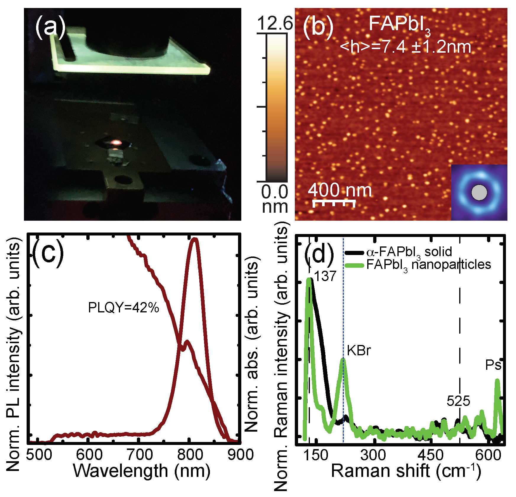
4. Formadinium-Based Perovskite Nanoparticles

Formamidinium lead iodide (HC(NH2)2I3, FAPbI3) is the rising star among perovskite materials due to its longer carrier lifetime [28,96,97]; higher photostability [38,96,98]; narrower band gap of 1.48 eV—making it suitable for absorption of near-infrared light [28,98,99,100]; and higher thermal stability [28,50] compared to MAPbI3. In addition, unlike MAPbI3-based devices, FAPbI3, with the n-i-p architecture (n-side illuminated), exhibits negligible hysteresis with sweep direction during current–voltage measurements [28,97,98,99,101,102]. Due to these advantages, it has become the key material for the highest-performance MHP solar cells, able to achieve record-breaking efficiency of 26% for FAPbI3 single crystal films [103,104] and has a record-breaking efficiency over 27% for all perovskite tandem devices [59].
However, it is more difficult to form stable perovskite phases and high-quality films with FAPbI3, requiring additives to stabilize the structures at room temperature [50,104]. As such, most high-stability devices are based on mixed cation–anion hybrids that incorporate several cations, anions, or both, with FAPbI3, including MAPbBr3 [100,101,105], MAPbI3 [97,106], Cs+ [107,108] or combinations thereof [109]. However, such substitutions often result in increased phase separation [49] caused by the presence of mixed halides and reduced photon absorption, owing to an undesirable increase in the band gap [50].
The instability of pure FAPbI3 results from its two main polymorphs: the  α  and  δ  phases [38]. The black trigonal  α -phase crystal is metastable at room temperature, forming above 60 °C and requiring temperatures above ∼150 °C to undergo a thermodynamic phase transition [37,99]. The yellow hexagonal  δ  phase, which is the thermodynamically stable phase at room temperature, is non-perovskite [38]. This undesirable yellow phase results from the distorted lattice due to the large size of the FA ion, near the upper limit of the Goldschmidt tolerance factor [5]. As a result, FAPbI3 readily transforms from the  α  to the  δ  phase under ambient conditions at room temperature, particularly in the presence of water [38,99].
Using the reverse micelle templating method, however, we produce monodisperse pure-phase FAPbI3 nanoparticles in the black  α  form at room temperature, which is stable in air under ambient conditions. The FAPbI3 micelles solution was spin-coated onto a Si substrate and illuminated with UV for verification of PL properties, as shown in Figure 5a. An image of the etched FAPbI3 nanoparticles is shown in Figure 5b, with the PL measurement from micelle-encapsulated nanoparticles showing a signature peak of the perovskite  α -FAPbI3 around 807 nm (Figure 5c). Typical  α -FAPbI3 single crystal have a PL peak at 820 nm, though Steele et al. also reported  α -FAPbI3 PL peak as low as 780 nm [38]. There also appears to be a long tail of weak emission down to 500 nm. Though this is likely from the unreacted precursor, we cannot rule out the formation of the non-emissive  δ -phase.
The Raman spectrum of these loaded micelles echoes the PL results that  α -FAPbI3 is formed inside the reverse micelles. The two phases of FAPbI3 show a similar yet shifted Raman spectrum, with a 30 cm 1  difference for the I-Pb-I bending and stretching mode between the  α  and  δ  phases [38,110]. The blue shift of this peak is a result of the lattice constant difference between the hexagonal structure of  δ -FAPbI3 and the trigonal structure of  α -FAPbI3 [38]. Figure 5d shows the Raman spectra of bulk FAPbI3 crystals precipitated from solution and the nanoparticles loaded inside the reverse micelles. Both spectra show the strong 137 cm 1  mode for  α -FAPbI3 from the I-Pb-I bending and stretching mode [38,110]. A weak broad band at 525 cm 1  related to the in-plane bending of the FA cation has been reported previously [38], but we did not observe it in either spectrum. The micelle-templated nanoparticles, deposited as a monolayer on KBr, also show a peak at 220 cm 1  which is the background peak from the KBr substrate, and at 620 cm 1  from the micellar shell. The FAPbI3 formed in solution was a chunk that was thick enough to block the laser from reaching the KBr substrate, and thus, there is no KBr peak in its spectrum. Though there is a 30 cm 1  Raman shift difference between the  α  and  δ  phase and it is close to the detection limit of the sensor at such low wave numbers, the possibility of a mixture of both phases forming in the micelles cannot be ruled out, given the long tail of emission visible in the PL. However, the preliminary results from Raman shows a promising formation of  α -FAPbI3, though we were unable to obtain high-quality XRD for further verification.
As they form inside the micellar nanoreactors, the size of the nanoparticles can only be determined after the polymeric micelles are removed by plasma etching. As shown in Figure 5b, the size of the  α -FAPbI3 nanoparticles is 8 nm, as measured from the AFM. Though the nanoparticles are more disordered than the other nanoparticles produced by RMD (see Figure 3), they have a relatively low PDI value of 0.16.
The reverse micelles technique proved to be a feasible way to synthesize stable  α -phase FAPbI3 nanoparticles at room temperature, likely due to three critical benefits of micelle templating. Firstly, the slower reaction kinetics resulting from a separation of the precursors allows for close interaction between PbI2 and FAI. Ahlawat et al. showed that a meso-porous network of PbI2 can act as a template for stabilized FAPbI3 thin films at room temperature by providing greater surface area for the interaction of the two components [37]. By virtue of the sequential loading, the micelle templates provide a natural separation between the FAI and PbI2, allowing for a high degree of interaction between the precursors that is not possible with a tightly packed film. Secondarily, the confined environment of the micelle can form unusual metastable phases. Zhao et al. showed that in highly confined environments, it is possible for dilute solutions of dissolved halide salts to spontaneously form 2D crystals [111]. It is therefore likely that the infiltration of the highly dilute lead salt into the nanoscale confined environment of the micelle results in the quasi-2D phase of PbI2, which Ahlawat et al. showed was necessary to form stable  α -phase FAPbI3 [37]. Finally, the micelle shell around the nanoparticle stabilizes the  α  phase, as it prevents the interaction of the particles with the ambient environment, particularly water [52,83]. Micelle-encapsulated FAPbBr3 nanoparticles were found by our group to maintain 83% of the initial emission, with only a small chromic shift (∼3 nm) for over 210 days [52] (see Supporting Information Figure S4). Due to the micellar shielding from water interaction, the  α  phase is able to maintain its integrity at room temperature.

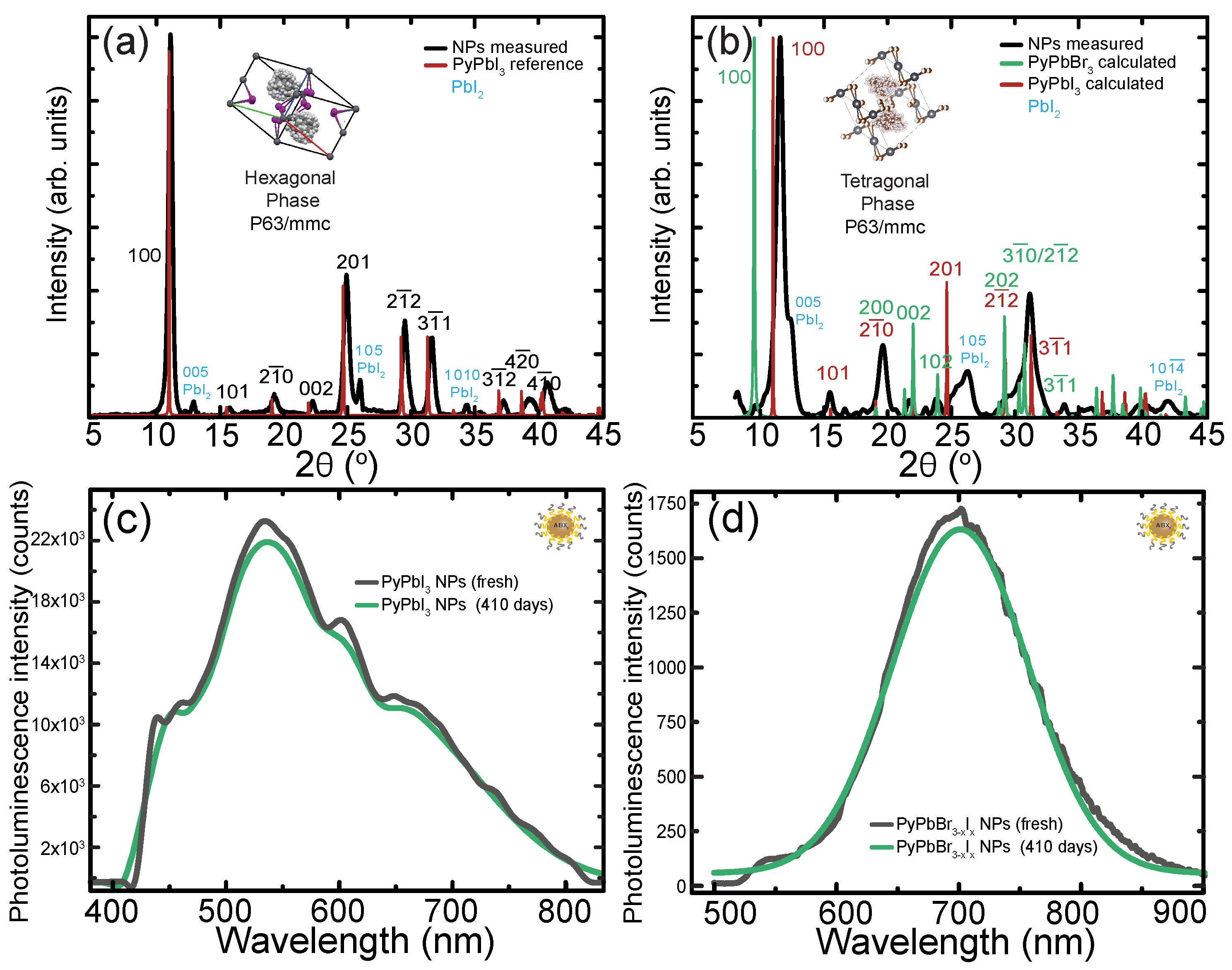
5. Pyrrolidinium Based Perovskite Nanoparticles

Recently, the introduction of larger ionic liquid cations, such as ammonium, pyrrolidinium, piperidinium, imidazolium, and pyridinium, into organo-halide perovskites has shown some novel electronic, luminescent, and stability properties [112,113,114,115]. In particular, pyrrolidine hydroiodide (PyI), with a large five-membered heterocycle pyrrolidinium ring, has led to novel high stability phases, both as a single crystal PyPbI3 and as a 1D stabilizer for MAI- and FAI-based perovskites [115,116,117,118,119]. Pyrrolidinium possesses  π  electrons, which are capable of forming anion- π  and  π π  interactions, resulting in a more rigid structure [113]. The large hydrophobic ring results in high temperature and moisture stability, with a band gap suitable for optoelectronic devices [119,120]. The rigid structure is also thought to reduce non-radiative transitions, which should yield higher PLQY [113].
Using reverse micelle templating, we produced pyrrolidinium-based perovskite nanoparticles by combining PyI with both iodide and bromide precursors, as shown in Figure 3. We did observe higher PLQY from these structures, as would be expected, as shown in Figure 3s,t. The formation of a crystalline perovskite phase was verified through XRD (Figure 6) for both types of nanoparticles encapsulated in the micelles. Using iodide-based precursors only, the data revealed a rhombohedral perovskites phase with  a = b = 9.3117  Å and  c = 8.180  Å lattice cell parameters, in good agreement with the determined bulk single crystal for PyPbI3 [120]. The observed and expected reflections for the nanoparticles and a theoretical PyPbI3 structure are indicated in Figure 6a and in Table 3. Reflections were also observed corresponding to the 0 0 5, 1 0 5 and 1 0 10 planes of lead iodide, indicating the presence of some unreacted precursor. Though some features (at 39.20, 40.69, and 42.53°) could also be attributed to PbI2, they should be less than 15% of the 0 0 5 reflection intensity. Given their higher intensity and the correspondence with the perovskite phase reflections, they are unlikely to have resulted from the precursor and were assigned to PyPbI3. To achieve these nanoparticles, we controlled the stoichiometric ratio of the two precursors to achieve a high degree of perovskite formation and only a small amount of precursor residue was observed. TEM measurements of the nanoparticles (not shown) do not show the large oval particles observed with an excess of precursor addition as described above for MAPbI3 nanoparticles, confirming strong perovskite formation for these Py-based nanoparticles.
Though single-crystal, 2D and 1D structures of PyPbI3 have been experimentally realized before [115,116,117,118,119], there have not been previous reports of any brominated structures with just lead at the B site ion. Here, by using the unconventional approach of an iodine-based organic precursor with PbBr2, as was used for MAPbBr3, we were able to achieve stable nanoparticles that showed an emission maximum at 701.5 nm. The ratio of iodine and bromine halides, as determined by EDS (not shown), is approximately 1:0.2 (I:Br). Typically, bromine-dominant perovskites emit in the green region of the spectrum and show a red shift with Br/I mixtures of increasing iodine content [121]. However, Zhang et al. found that PyMnBr3 perovskites have an emission maximum at 640 nm, suggesting that perovskites with a larger Py cation differ from other MHPs with respect to the impact of the halide. In fact, Kusumawati et al. [112] calculated the photophysical properties of pyrrolidinium, showing a phosphorescence maximum of around 659.5 nm, suggesting that this may be the dominant emission for such a brominated system [113]. Regardless, there is a distinct shift in the emission spectrum from that observed for just iodine precursors, suggesting a bromide-dominated system or a mixed halide phase.
We compared the experimental XRD spectra shown in Figure 6b and Table 3 to the ideal unit cell for both PyPbI3 and PyPbBr3, showing strong correspondence between the experimental and theoretical data. Though there are a number of features that can be attributed to PyPbBr3 directly (green spectrum), there seems to be only a small amount of this phase, as the {1 0 0} at 9.5° is expected to be the strongest reflex but is only just visible in the spectrum. Reflections at 21.67 and 24.10° can be assigned solely to PyPbBr3, but many other features overlap with reflections expected from PyPbI3 or, like the feature around 30°, are a convolution of closely spaced reflections from both phases. The feature at 19.5° is more intense than expected with respect to either 2 0 0 for PyPbI3 or 2  1 -  0 for PyPbBr3. Rao et al. [116] showed a similar intense feature in their XRD pattern for PyPbI3 between the 1 1 0 and 0 0 2 planes, which they did not assign, so it may arise from some other feature or be the result of a different texture than the expected <1 0 0> directions [119]. Though we tried modelling other ideal structures using a mixture of I/Br ions, most appeared similar to the PyPbI3 phase. The strong features can be most closely attributed to the P63/mmc structure of PyPbI3, suggesting that our nanoparticles have a PyPbBr3-xIx structure.
The formation of these mixed halide materials as nanoparticles is unusual, as there have been no previous reports on mixed halide structures incorporating the large Py ions. A comparison of the emission spectrum between PyPbBr3−xIx nanoparticles formed in the micelles and a mixture of the two precursors in o-xylene without the micelles is shown in Supporting Information, Figure S5. The precipitates exhibited a broad emission spectrum without a prominent emission maxima. We have observed similar ambiguous emissions from unreacted perovskite salts, which could also suggest that the precursors did not react fully. Therefore, it is unlikely that there was any significant perovskite formation without the micelle templating. The XRD measurements of the resulting precipitates (Supporting Information, Figure S5) did not show any significant crystallinity, though there was a broad feature around 19.5°. This suggests that this feature in the nanoparticle spectrum may actually be due to the unreacted precursors. Therefore, it appears that the nanoreactors lead to the formation of mixed halide phases that cannot be attained under ambient conditions without the PS-b-P2VP reverse micelles.
Though the XRD for both pyrrolidinium-based nanoparticles was consistent with the unit cell of hexagonal PyPbI3, the reflection centres were shifted to higher values relative to the reference spectra for both, suggesting the development of compressive strain with lattice deformation [32].
The strain in perovskite nanoparticles can be calculated using the Cauchy–Gaussian approximation [122,123]. The primary equation of the Cauchy–Sherrer approximation is
β cos Θ = ( λ / L ) + 4 e sin Θ
where  λ  is the X-ray wavelength, L refers to crystallite size, and e refers to strain. By subtracting the instrumental broadening factor from the experimentally obtained line profile, a pure line profile is generated. The obtained pure line profile can then be used to calculate crystallite size and lattice strain using the following expression:
β = δ ( 2 Θ ) = B ( 1 b 2 / B 2 ) ( r a d )
where  2 Θ  is the diffraction angle and B and b are the breadths of the same Bragg reflection from the experimental and reference XRD scans, respectively, which in our case are the full-width half maximums (FWHMs).
The Sherrer equation was then used to calculate the crystal sizes and average diameters of the crystallites.
L = D λ / β C o s Θ
where  Θ  represents the Bragg angle, L represents crystal size, and D represents the shape factor, which is approximately one. The calculated values were then entered into Equation (3) to obtain the induced strain in the perovskite nanoparticles.
Using this approximation, the PyPbI3 nanoparticles were found to have a strain of −4.98%, and the PyPbBr3−xIx was found to have a strain of −11.3%, relative to a PyPbI3 single crystal, respectively. Generally, the introduction of small ions into strained structures results in strain relaxation [33,124], but we observed an increase in compressive strain for the mixed halide perovskites, suggesting greater distortion of the lattice. This could be another explanation for the red-shifted emission observed with these bromine-dominated phase particles, which show substantially higher compressive strain than the iodine-dominated nanoparticles. The compressive strain has been observed for other perovskite systems to lead to dramatic redshifts in the emission profile.
We attribute the strain in both cases as resulting from the external pressure of the micelle core on the perovskite cage during particle formation. The induced strain has been previously observed for other types of ligated [125,126] and core-shell [127,128] nanoparticles. Quantitative nanomechanical mapping (QNM) using the AFM can provide information on the nanomechanical properties of soft materials [129,130,131]. For the micelle structures, hardness maps were created by calculating the elastic modulus at each AFM interaction point using the Derjaguin–Müller-Toporov (DMT) model to fit the unloading portion of the force–indentation curves [131]. We have previously observed that the infiltration of precursor salts into the micelles can lead to a change in Young’s modulus as a function of the loading [26,131]. Similar to Liu et al. [132], we assume that a stress transfer through the micelle during swelling with salt infiltration results in a variation in the locally measured modulus; thus, we treat this variation as the nano stress in each micelle, assuming that the micelle is in the elastic limit [132]. Figure S7 in the supporting information shows the average change in the nanostress (as defined by the relative ratio of Young’s modulus of the loaded and unloaded micelles) developed in the centre of the micelle due to the infiltration of the organic salt. As the loading increases, higher stress can be observed within the micelles. When the nanoparticle is formed with the loading of both precursors, the stress reaches a plateau [131]. This increased pressure within the micelle during particle loading and formation could result in the induced strain observed in the perovskite cage, particularly for larger anions.
Having a large five-membered heterocycle Py ring-based structure has been seen to greatly improve the stability of organo-halide perovskites single crystals [116,118,119,120]. The larger hydrophobic ring was successful in stabilizing single crystals in the presence of water for 4 months [119], as well as stabilizing methylammonium- and formadinium-based perovskites [115,116]. We see this behaviour continue in the micelle-encapsulated nanoparticles, as shown in Figure 6c,d for both PyPbI3 and mixed-phase nanoparticles, respectively. With polymer encapsulation in the micelle, the nanoparticles retain 95–97% of their original emission intensity, with no shift in the emission wavelength, for over 410 days of exposure to ambient conditions (see Supporting Information Figure S6 for a comparison of the peak wavelengths and FWHM for fresh and aged nanoparticles). While the micelle encapsulation contributes to this stability, as FAPbBr3 nanoparticles were also shown to have long stability in ambient conditions [52] (see Supporting Information Figure S4), the pyrrolidinium-based nanoparticles were able to last 200 days longer with almost no loss in emissive properties. This suggests that the enhanced stability results from the more stable ring structure compared to the smaller, more volatile organic cations, in combination with the micellar shielding.

6. Discussion

Through the use of reverse micelle templates, various unusual behaviours and structures can be achieved from perovskites that result from the confined environment provided by the micelle nanoreactors. The reverse micelle synthesis route restricts the ions within the nanoreactor and allows for the encapsulation and rotation of the cage for perovskite formation.
Unlike in ligated approaches, the micelle polymer chains are not chemically anchored to the perovskite surface; instead, the reverse micelle provides a confined environment for the precursor salts. The salts are localized within the micelle structure typically due to osmotic pressure or through interaction with the unpaired electrons on the pyridine groups, which form the core of the micelle. Most of the organic cations used for the formation of perovskites are a form of protic or aprotic ionic liquid, where the cation consists of an asymmetrical organic species, with one or more organic groups appended to the cation core, and the anion is a halide [113,133]. Using the reverse micelle method, we have seen that for dense core micelles, organic cations coordinated with iodine are more successfully incorporated into the micelle structure, likely due to the high affinity between the unpaired electrons on pyridine and the iodine groups [51]. As this is an ionic compound, the halide interaction with the P2VP leaves the organic cation free to interact with other precursor salts inside the micellar environment. The addition of the iodide stabilizes the core via quaternization with the P2VP group of the diblock copolymer while leaving it unchanged in the presence of a more reactive ion [84], making the micelle more stable and allowing the incorporation of salts that would otherwise destroy the micelle structure [26].
However, this process also increases the pressure of the micelle as more and more precursor loading is performed. It is likely that the confined, strained environment inside the micelle leads to the formation of unusual phases discussed in this contribution: in the case of MAPbI3, we observed the emergence of the orthrhombic phase at room temperature, which is a strained phase relative to the tetragonal room-temperature phase usually observed; FAPbI3 requires the dilute confined polar environment inside the micelle to encourage the formation of the quasi-2D form of PbI2 that can lead to a room-temperature stable perovskite phase; the confined environment of the micelle core induces a strain in the crystal structures for the large Py A site cations, which may contribute to the red shift in emission to 700 nm for mixed halide perovskites.
The micellar environment also has the added benefit of slowing down the reaction kinetics by separating the precursor solvation and combination steps. This allows for the formation of perovskite structures from a mixture of organic iodides and lead bromides that are not possible using mixing these precursors without the micelles, by utilizing neither other ligand-assisted nor bulk-synthesis approaches. Interestingly, these unconventionally formed nanoparticles do not result from a halide ion exchange between perovskites; rather, they are formed through the infiltration of Br ions, which then interact with the organic cation directly, resulting in a stabilized perovskite cage dominated by bromine. For the smaller methylammonium and formadinium A site cations, this results in the formation of the thermodynamically stable APBr3-dominated nanoparticles, which would be suppressed in the fast reaction kinetics of ligand-assisted approaches. By tuning the infiltration of iodide A and bromide B precursors, it is possible to form nanoparticles that emit in either the red or green parts of the spectrum or from both simultaneously [10]. For the large pyrrolidinium cation, where no brominated or mixed halide structures have yet been reported, an emissive tetragonal phase was able to be produced for the micelle-templated particles, showing an unusual bathochromic shift in emission relative to its iodide-based counterpart.
Another compelling aspect of reverse micelle templating is the inherent stability it imparts to the synthesized perovskite materials. The encapsulation of precursor species within the micellar cores provides a protective shield against environmental factors, resulting in resilient nanoparticles when they are exposed to ambient conditions. This stability is further enhanced when combined with other strategies such as anionic exchange or the incorporation of large aromatic cations, ensuring the long-term integrity of the perovskite structure, with little to no chromic shift, even after two years of being stored in air.

7. Conclusions

Reverse micelle templating has emerged as an elegant and energy-efficient avenue for achieving arrays of well-dispersed perovskite nanoparticles. In this approach, the diblock copolymer templates play a pivotal role by effectively confining precursor species within the cores of the reverse micelles. This spatial constraint imparts a unique advantage, enabling the formation of perovskite phases at room temperature that are not observed using conventional synthesis routes. These unique structural attributes can be attributed to the distinct confinement and reduced reaction kinetics within the micellar environment. Such unusual phases can pave the way for the development of novel perovskite materials with distinct properties and applications, taking advantage of the properties of reverse micelles. By manipulating the composition and properties of the reverse micelle template, we have been able to manipulate the structure and emission characteristics of the resulting perovskite nanoparticles, opening up exciting opportunities for customizing optical properties to suit various applications. The versatility, tunability, stability, and ability to form unconventional perovskite phases using reverse micelle templating for perovskite synthesis make it an attractive avenue to broaden perovskite research and harness the full potential of perovskite materials in various scientific and technological domains, tailoring perovskite properties to meet specific application requirements.

Supplementary Materials

The following are available online at https://www.mdpi.com/article/10.3390/chemistry5040163/s1. Figure S1: (a–c) AFM images of unloaded, and loaded polymer micelles before and after oxygen plasma treatment for MAPbBr3 nanoparticles. (d–f) The Voronoi tessellations are used to quantify the nanoparticle order where the colour indicates the number of nearest neighbours (g–i) The probability distribution with respect to number of nearest neighbours of the Voronoi tesselation. (j–l) Histogram of particle heights. Figure S2: Comparison of the photoluminescence peak properties as a function of the precursor salt ratios (a) integrated area (b) maximum intensity (c) emission wavelength at peak maximum (d) full width half max (FWHM). Figure S3: AFM images of MAPbI3 nanoparticles with different precursor salt ratios. The Voronoi tessellations are used to quantify order where the colour indicates the deviation of the cell area relative to a perfect hexagonal lattice, the histogram of the probability distribution of the deviation with respect to the hexagonal cell area is also shown. Normalized photoluminescence spectra with the photoluminescence quantum yield is included in the bottom row. Figure S4: Photoluminescence spectra for micelle encapsulated FAPbBr3 nanoparticles spin coated on Si substrates and exposed to the ambient atmosphere for various lengths of time. Figure S5: (a) Photoluminescence spectra of drop-cast solutions on Si substrates produced from adding PyI and PbBr2 to o-xylene solutions with and without PS-b-P2VP micelles (b) XRD spectrum of PyI and PbBr2 mixed in o-xylene solutions to produce bulk precipitates. Figure S6: Comparison of the photoluminescence peak properties for Py based perovskite nanoparticles (a–b) emission wavelength at peak maximum (c–d) full width half max (FWHM). Note that the PyPbI3 nanoparticles exhibit a broad emission that can be deconvoluted into two peaks, emission attributed to the hexagonal phase observed in the XRD pattern at around 530nm, as well as a peak at 660 nm that appears to be due to the bulk phase. Figure S7: Developed stress inside the micelle during salt loading determined by taking the ratio of the unloaded to loaded micelle. Table S1: Resultant crystal structure for simulated PyPbI3 and PyPbBr3 crystals in Vesta.

Author Contributions

Conceptualization, A.T.; methodology, M.M., L.S.H. and A.T.; formal analysis, M.M., L.S.H. and A.S.; investigation, M.M. and L.S.H.; resources, A.T.; data curation, A.T.; writing—original draft preparation, M.M., L.S.H. and A.T.; writing—review and editing, A.T.; visualization, M.M., L.S.H., A.S. and A.T.; supervision, A.T.; project administration, A.T.; funding acquisition, A.T. All authors have read and agreed to the published version of the manuscript.

Funding

This research was funded by the Ontario Ministry of Research and Innovation (Early Researcher Award, ER15-11-123), the Natural Science and Engineering Research Council of Canada (Discovery Grant, RGPIN-2019-05994), and Satellite Canada Innovation Network (HTSN-611, and HTSN-621), Concordia University (Faculty Development Development Grant 300010308).

Data Availability Statement

The data presented in this study are available on request from the corresponding author.

Acknowledgments

The authors thank the McMaster Centre for Advanced Light Microscopy (CALM) and Centre for NanoScience Research (CeNSR) for access to the AFM for measurements, the Canadian Centre for Electron Microscopy) (CCEM) for TEM measurements, and McMaster X-ray Diffraction Facility (MAX) for XRD.

Conflicts of Interest

The authors declare no conflict of interest.

References

  1. Ling, Y.; Yuan, Z.; Tian, Y.; Wang, X.; Wang, J.C.; Xin, Y.; Hanson, K.; Ma, B.; Gao, H. Bright Light-Emitting Diodes Based on Organometal Halide Perovskite Nanoplatelets. Adv. Mater. 2016, 28, 305–311. [Google Scholar] [CrossRef] [PubMed]
  2. Liu, X.K.; Xu, W.; Bai, S.; Jin, Y.; Wang, J.; Friend, R.H.; Gao, F. Metal Halide Perovskites for Light-Emitting Diodes. Nat. Mater. 2021, 20, 10–21. [Google Scholar] [CrossRef] [PubMed]
  3. Snaith, H.J. Present Status and Future Prospects of Perovskite Photovoltaics. Nat. Mater. 2018, 17, 372–376. [Google Scholar] [CrossRef] [PubMed]
  4. Jena, A.K.; Kulkarni, A.; Miyasaka, T. Halide Perovskite Photovoltaics: Background, Status, and Future Prospects. Chem. Rev. 2019, 119, 3036–3103. [Google Scholar] [CrossRef]
  5. Correa-Baena, J.P.; Saliba, M.; Buonassisi, T.; Grätzel, M.; Abate, A.; Tress, W.; Hagfeldt, A. Promises and Challenges of Perovskite Solar Cells. Science 2017, 358, 739–744. [Google Scholar] [CrossRef]
  6. Moon, J.; Mehta, Y.; Gundogdu, K.; So, F.; Gu, Q. Metal-Halide Perovskite Lasers: Cavity Formation and Emission Characteristics. Adv. Mater. 2023, 2211284. [Google Scholar] [CrossRef] [PubMed]
  7. Zhang, Q.; Shang, Q.; Su, R.; Do, T.T.H.; Xiong, Q. Halide Perovskite Semiconductor Lasers: Materials, Cavity Design, and Low Threshold. Nano Lett. 2021, 21, 1903–1914. [Google Scholar] [CrossRef]
  8. Eaton, S.W.; Lai, M.; Gibson, N.A.; Wong, A.B.; Dou, L.; Ma, J.; Wang, L.W.; Leone, S.R.; Yang, P. Lasing in Robust Cesium Lead Halide Perovskite Nanowires. Proc. Natl. Acad. Sci. USA 2016, 113, 1993–1998. [Google Scholar] [CrossRef]
  9. Sutherland, B.R.; Sargent, E.H. Perovskite Photonic Sources. Nat. Photonics 2016, 10, 295–302. [Google Scholar] [CrossRef]
  10. Munir, M.; Tan, J.; Arbi, R.; Oliveira, P.; Leeb, E.; Salinas, Y.; Scharber, M.C.; Sariciftci, N.S.; Turak, A. Enhanced Stokes Shift and Phase Stability by Cosynthesizing Perovskite Nanoparticles (MAPbI3/MAPbBr3) in a Single Solution. Adv. Photonics Res. 2022, 3, 2100372. [Google Scholar] [CrossRef]
  11. Tan, J.; Munir, M.; Arbi, R.; Turak, A. Matching Emission and Absorption Profiles for Improved Performance in OPVs with Perovskite Nanoparticle Down-Converters. In Proceedings of the 2023 Photonics North PN, Montreal, QC, Canada, 12–15 June 2023; IEEE: Montreal QC, Canada, 2023; Volume PN58661, p. 10222968. [Google Scholar] [CrossRef]
  12. Wang, J.; Liu, J.; Du, Z.; Li, Z. Recent Advances in Metal Halide Perovskite Photocatalysts: Properties, Synthesis and Applications. J. Energy Chem. 2021, 54, 770–785. [Google Scholar] [CrossRef]
  13. Zheng, W.; Wang, X.; Zhang, X.; Chen, B.; Suo, H.; Xing, Z.; Wang, Y.; Wei, H.L.; Chen, J.; Guo, Y.; et al. Emerging Halide Perovskite Ferroelectrics. Adv. Mater. 2023, 35, 2205410. [Google Scholar] [CrossRef] [PubMed]
  14. De Wolf, S.; Holovsky, J.; Moon, S.J.; Löper, P.; Niesen, B.; Ledinsky, M.; Haug, F.J.; Yum, J.H.; Ballif, C. Organometallic Halide Perovskites: Sharp Optical Absorption Edge and Its Relation to Photovoltaic Performance. J. Phys. Chem. Lett. 2014, 5, 1035–1039. [Google Scholar] [CrossRef] [PubMed]
  15. Maes, J.; Balcaen, L.; Drijvers, E.; Zhao, Q.; De Roo, J.; Vantomme, A.; Vanhaecke, F.; Geiregat, P.; Hens, Z. Light Absorption Coefficient of CsPbBr3 Perovskite Nanocrystals. J. Phys. Chem. Lett. 2018, 9, 3093–3097. [Google Scholar] [CrossRef]
  16. Hintermayr, V.A.; Richter, A.F.; Ehrat, F.; Döblinger, M.; Vanderlinden, W.; Sichert, J.A.; Tong, Y.; Polavarapu, L.; Feldmann, J.; Urban, A.S. Tuning the Optical Properties of Perovskite Nanoplatelets through Composition and Thickness by Ligand-Assisted Exfoliation. Adv. Mater. 2016, 28, 9478–9485. [Google Scholar] [CrossRef] [PubMed]
  17. Yin, W.J.; Shi, T.; Yan, Y. Unusual Defect Physics in CH3NH3PbI3 Perovskite Solar Cell Absorber. Appl. Phys. Lett. 2014, 104, 063903. [Google Scholar] [CrossRef]
  18. Stranks, S.D.; Eperon, G.E.; Grancini, G.; Menelaou, C.; Alcocer, M.J.P.; Leijtens, T.; Herz, L.M.; Petrozza, A.; Snaith, H.J. Electron-Hole Diffusion Lengths Exceeding 1 Micrometer in an Organometal Trihalide Perovskite Absorber. Science 2013, 342, 341–344. [Google Scholar] [CrossRef]
  19. Turren-Cruz, S.H.; Hagfeldt, A.; Saliba, M. Methylammonium-Free, High-Performance, and Stable Perovskite Solar Cells on a Planar Architecture. Science 2018, 362, 449–453. [Google Scholar] [CrossRef]
  20. Saparov, B.; Mitzi, D.B. Organic–Inorganic Perovskites: Structural Versatility for Functional Materials Design. Chem. Rev. 2016, 116, 4558–4596. [Google Scholar] [CrossRef]
  21. Liang, Z.; Zhao, S.; Xu, Z.; Qiao, B.; Song, P.; Gao, D.; Xu, X. Shape-Controlled Synthesis of All-Inorganic CsPbBr3 Perovskite Nanocrystals with Bright Blue Emission. ACS Appl. Mater. Interfaces 2016, 8, 28824–28830. [Google Scholar] [CrossRef]
  22. Goldschmidt, V.M. Die Gesetze der Krystallochemie. Naturwissenschaften 1926, 14, 477–485. [Google Scholar] [CrossRef]
  23. Filip, M.R.; Eperon, G.E.; Snaith, H.J.; Giustino, F. Steric Engineering of Metal-Halide Perovskites with Tunable Optical Band Gaps. Nat. Commun. 2014, 5, 5757. [Google Scholar] [CrossRef]
  24. Kieslich, G.; Sun, S.; Cheetham, A.K. Solid-State Principles Applied to Organic–Inorganic Perovskites: New Tricks for an Old Dog. Chem. Sci. 2014, 5, 4712–4715. [Google Scholar] [CrossRef]
  25. Fu, Y.; Hautzinger, M.P.; Luo, Z.; Wang, F.; Pan, D.; Aristov, M.M.; Guzei, I.A.; Pan, A.; Zhu, X.; Jin, S. Incorporating Large A Cations into Lead Iodide Perovskite Cages: Relaxed Goldschmidt Tolerance Factor and Impact on Exciton–Phonon Interaction. ACS Cent. Sci. 2019, 5, 1377–1386. [Google Scholar] [CrossRef] [PubMed]
  26. Hui, L.S.; Beswick, C.; Getachew, A.; Heilbrunner, H.; Liang, K.; Hanta, G.; Arbi, R.; Munir, M.; Dawood, H.; Isik Goktas, N.; et al. Reverse Micelle Templating Route to Ordered Monodispersed Spherical Organo-Lead Halide Perovskite Nanoparticles for Light Emission. ACS Appl. Nano Mater. 2019, 2, 4121–4132. [Google Scholar] [CrossRef]
  27. Fan, Y.; Meng, H.; Wang, L.; Pang, S. Review of Stability Enhancement for Formamidinium-Based Perovskites. Sol. RRL 2019, 3, 1900215. [Google Scholar] [CrossRef]
  28. Eperon, G.E.; Stranks, S.D.; Menelaou, C.; Johnston, M.B.; Herz, L.M.; Snaith, H.J. Formamidinium Lead Trihalide: A Broadly Tunable Perovskite for Efficient Planar Heterojunction Solar Cells. Energy Environ. Sci. 2014, 7, 982–988. [Google Scholar] [CrossRef]
  29. Deng, Y.; Zheng, X.; Bai, Y.; Wang, Q.; Zhao, J.; Huang, J. Surfactant-Controlled Ink Drying Enables High-Speed Deposition of Perovskite Films for Efficient Photovoltaic Modules. Nat. Energy 2018, 3, 560–566. [Google Scholar] [CrossRef]
  30. Zhou, C.; Lin, H.; He, Q.; Xu, L.; Worku, M.; Chaaban, M.; Lee, S.; Shi, X.; Du, M.H.; Ma, B. Low Dimensional Metal Halide Perovskites and Hybrids. Mater. Sci. Eng. R Rep. 2019, 137, 38–65. [Google Scholar] [CrossRef]
  31. Lin, H.; Zhou, C.; Tian, Y.; Siegrist, T.; Ma, B. Low-Dimensional Organometal Halide Perovskites. ACS Energy Lett. 2018, 3, 54–62. [Google Scholar] [CrossRef]
  32. Yang, B.; Bogachuk, D.; Suo, J.; Wagner, L.; Kim, H.; Lim, J.; Hinsch, A.; Boschloo, G.; Nazeeruddin, M.K.; Hagfeldt, A. Strain Effects on Halide Perovskite Solar Cells. Chem. Soc. Rev. 2022, 51, 7509–7530. [Google Scholar] [CrossRef] [PubMed]
  33. Lu, C.H.; Biesold-McGee, G.V.; Liu, Y.; Kang, Z.; Lin, Z. Doping and Ion Substitution in Colloidal Metal Halide Perovskite Nanocrystals. Chem. Soc. Rev. 2020, 49, 4953–5007. [Google Scholar] [CrossRef]
  34. Liu, D.; Luo, D.; Iqbal, A.N.; Orr, K.W.P.; Doherty, T.A.S.; Lu, Z.H.; Stranks, S.D.; Zhang, W. Strain Analysis and Engineering in Halide Perovskite Photovoltaics. Nat. Mater. 2021, 20, 1337–1346. [Google Scholar] [CrossRef] [PubMed]
  35. Jing, H.; Sa, R.; Xu, G. Tuning Electronic and Optical Properties of CsPbI3 by Applying Strain: A First-Principles Theoretical Study. Chem. Phys. Lett. 2019, 732, 136642. [Google Scholar] [CrossRef]
  36. Edri, E.; Kirmayer, S.; Kulbak, M.; Hodes, G.; Cahen, D. Chloride Inclusion and Hole Transport Material Doping to Improve Methyl Ammonium Lead Bromide Perovskite-Based High Open-Circuit Voltage Solar Cells. J. Phys. Chem. Lett. 2014, 5, 429–433. [Google Scholar] [CrossRef]
  37. Ahlawat, P.; Hinderhofer, A.; Alharbi, E.A.; Lu, H.; Ummadisingu, A.; Niu, H.; Invernizzi, M.; Zakeeruddin, S.M.; Dar, M.I.; Schreiber, F.; et al. A Combined Molecular Dynamics and Experimental Study of Two-Step Process Enabling Low-Temperature Formation of Phase-Pure α-FAPbI3. Sci. Adv. 2021, 7, eabe3326. [Google Scholar] [CrossRef]
  38. Steele, J.A.; Yuan, H.; Tan, C.Y.X.; Keshavarz, M.; Steuwe, C.; Roeffaers, M.B.J.; Hofkens, J. Direct Laser Writing of δ- to α-Phase Transformation in Formamidinium Lead Iodide. ACS Nano 2017, 11, 8072–8083. [Google Scholar] [CrossRef]
  39. Kulkarni, S.A.; Mhaisalkar, S.G.; Mathews, N.; Boix, P.P. Perovskite Nanoparticles: Synthesis, Properties, and Novel Applications in Photovoltaics and LEDs. Small Methods 2019, 3, 1800231. [Google Scholar] [CrossRef]
  40. Prochazkova, A.J.; Mayr, F.; Gugujonovic, K.; Hailegnaw, B.; Krajcovic, J.; Salinas, Y.; Brüggemann, O.; Sariciftci, N.S.; Scharber, M.C. Anti-Stokes Photoluminescence Study on a Methylammonium Lead Bromide Nanoparticle Film. Nanoscale 2020, 12, 16556–16561. [Google Scholar] [CrossRef]
  41. Bhaumik, S.; Veldhuis, S.A.; Ng, Y.F.; Li, M.; Muduli, S.K.; Sum, T.C.; Damodaran, B.; Mhaisalkar, S.; Mathews, N. Highly Stable, Luminescent Core–Shell Type Methylammonium–Octylammonium Lead Bromide Layered Perovskite Nanoparticles. Chem. Commun. 2016, 52, 7118–7121. [Google Scholar] [CrossRef]
  42. Sun, S.; Yuan, D.; Xu, Y.; Wang, A.; Deng, Z. Ligand-Mediated Synthesis of Shape-Controlled Cesium Lead Halide Perovskite Nanocrystals via Reprecipitation Process at Room Temperature. ACS Nano 2016, 10, 3648–3657. [Google Scholar] [CrossRef] [PubMed]
  43. Demchyshyn, S.; Roemer, J.M.; Groiß, H.; Heilbrunner, H.; Ulbricht, C.; Apaydin, D.; Böhm, A.; Rütt, U.; Bertram, F.; Hesser, G.; et al. Confining Metal-Halide Perovskites in Nanoporous Thin Films. Sci. Adv. 2017, 3, e1700738. [Google Scholar] [CrossRef] [PubMed]
  44. Yi, Z.; Ladi, N.H.; Shai, X.; Li, H.; Shen, Y.; Wang, M. Will Organic–Inorganic Hybrid Halide Lead Perovskites Be Eliminated from Optoelectronic Applications? Nanoscale Adv. 2019, 1, 1276–1289. [Google Scholar] [CrossRef]
  45. Schmidt, L.C.; Pertegás, A.; González-Carrero, S.; Malinkiewicz, O.; Agouram, S.; Mínguez Espallargas, G.; Bolink, H.J.; Galian, R.E.; Pérez-Prieto, J. Nontemplate Synthesis of CH3NH3PbBr3 Perovskite Nanoparticles. J. Am. Chem. Soc. 2014, 136, 850–853. [Google Scholar] [CrossRef] [PubMed]
  46. Chauhan, M.; Zhong, Y.; Schötz, K.; Tripathi, B.; Köhler, A.; Huettner, S.; Panzer, F. Investigating Two-Step MAPbI 3 Thin Film Formation during Spin Coating by Simultaneous in Situ Absorption and Photoluminescence Spectroscopy. J. Mater. Chem. A 2020, 8, 5086–5094. [Google Scholar] [CrossRef]
  47. Esaka, H.; Kurz, W. Columnar Dendrite Growth: Experiments on Tip Growth. J. Cryst. Growth 1985, 72, 578–584. [Google Scholar] [CrossRef]
  48. Zhang, C.; Wang, Y.; Lin, X.; Wu, T.; Han, Q.; Zhang, Y.; Han, L. Effects of A Site Doping on the Crystallization of Perovskite Films. J. Mater. Chem. A 2021, 9, 1372–1394. [Google Scholar] [CrossRef]
  49. Hoke, E.T.; Slotcavage, D.J.; Dohner, E.R.; Bowring, A.R.; Karunadasa, H.I.; McGehee, M.D. Reversible Photo-Induced Trap Formation in Mixed-Halide Hybrid Perovskites for Photovoltaics. Chem. Sci. 2015, 6, 613–617. [Google Scholar] [CrossRef]
  50. Min, H.; Kim, M.; Lee, S.U.; Kim, H.; Kim, G.; Choi, K.; Lee, J.H.; Seok, S.I. Efficient, Stable Solar Cells by Using Inherent Bandgap of α-Phase Formamidinium Lead Iodide. Science 2019, 366, 749–753. [Google Scholar] [CrossRef]
  51. Turak, A. Reverse Micelles as a Universal Route to Solution Processed Nanoparticles for Optical, Optoelectronic and Photonic Applications: A Story of Salt Complexation, Micellar Stability, and Nanoparticle Spatial Distribution. Vid. Proc. Adv. Mater. 2021, 2, 2103166. [Google Scholar]
  52. Turak, A. Perovskite Nanoparticles on Demand: Highly Stable Nanoparticles Using Reverse Micelle Templating. In Proceedings of the 2023 Photonics North PN, Montreal, QC, Canada, 12–15 June 2023; IEEE: Montreal QC, Canada, 2023; Volume PN58661, p. 10222995. [Google Scholar] [CrossRef]
  53. Hui, L.S.; Munir, M.; Vuong, A.; Hilke, M.; Wong, V.; Fanchini, G.; Scharber, M.C.; Sariciftci, N.S.; Turak, A. Universal Transfer Printing of Micelle-Templated Nanoparticles Using Plasma-Functionalized Graphene. ACS Appl. Mater. Interfaces 2020, 12, 46530–46538. [Google Scholar] [CrossRef] [PubMed]
  54. Munir, M.; Arbi, R.; Scharber, M.C.; Salinas, Y.; Sariciftci, N.S.; Turak, A. Anionic Exchange Route to Synthesize Highly Uniform, Stable and Luminescent MAPBr Nanoparticles. OSA Tech. Dig. 2020, 2020, PvTu3G.5. [Google Scholar] [CrossRef]
  55. Danaei, M.; Dehghankhold, M.; Ataei, S.; Hasanzadeh Davarani, F.; Javanmard, R.; Dokhani, A.; Khorasani, S.; Mozafari, M.R. Impact of Particle Size and Polydispersity Index on the Clinical Applications of Lipidic Nanocarrier Systems. Pharmaceutics 2018, 10, 57. [Google Scholar] [CrossRef] [PubMed]
  56. Mudalige, T.; Qu, H.; Van Haute, D.; Ansar, S.M.; Paredes, A.; Ingle, T. Characterization of Nanomaterials: Tools and Challenges. In Nanomaterials for Food Applications; López Rubio, A., Fabra Rovira, M.J., Martínez Sanz, M., Gómez-Mascaraque, L.G., Eds.; Micro and Nano Technologies; Elsevier: Amsterdam, The Netherlands, 2019; pp. 313–353. [Google Scholar] [CrossRef]
  57. Stavis, S.M.; Fagan, J.A.; Stopa, M.; Liddle, J.A. Nanoparticle Manufacturing–Heterogeneity through Processes to Products. ACS Appl. Nano Mater. 2018, 1, 4358–4385. [Google Scholar] [CrossRef]
  58. Moerman, D.; Eperon, G.E.; Precht, J.T.; Ginger, D.S. Correlating Photoluminescence Heterogeneity with Local Electronic Properties in Methylammonium Lead Tribromide Perovskite Thin Films. Chem. Mater. 2017, 29, 5484–5492. [Google Scholar] [CrossRef]
  59. He, R.; Wang, W.; Yi, Z.; Lang, F.; Chen, C.; Luo, J.; Zhu, J.; Thiesbrummel, J.; Shah, S.; Wei, K.; et al. Improving Interface Quality for 1-Cm2 All-Perovskite Tandem Solar Cells. Nature 2023, 618, 80–86. [Google Scholar] [CrossRef]
  60. Tan, S.; Huang, T.; Yavuz, I.; Wang, R.; Yoon, T.W.; Xu, M.; Xing, Q.; Park, K.; Lee, D.K.; Chen, C.H.; et al. Stability-Limiting Heterointerfaces of Perovskite Photovoltaics. Nature 2022, 605, 268–273. [Google Scholar] [CrossRef]
  61. Mitzi, D.B. Synthesis, Structure, and Properties of Organic-Inorganic Perovskites and Related Materials. In Progress in Inorganic Chemistry; John Wiley & Sons, Ltd.: Hoboken, NJ, USA, 1999; pp. 1–121. [Google Scholar] [CrossRef]
  62. Kojima, A.; Teshima, K.; Shirai, Y.; Miyasaka, T. Organometal Halide Perovskites as Visible- Light Sensitizers for Photovoltaic Cells. J. Am. Chem. Soc. 2009, 131, 6050–6051. [Google Scholar] [CrossRef]
  63. Im, J.H.; Lee, C.R.; Lee, J.W.; Park, S.W.; Park, N.G. 6.5% Efficient Perovskite Quantum-Dot-Sensitized Solar Cell. Nanoscale 2011, 3, 4088–4093. [Google Scholar] [CrossRef]
  64. Lee, M.M.; Teuscher, J.; Miyasaka, T.; Murakami, T.N.; Snaith, H.J. Efficient Hybrid Solar Cells Based on Meso-Superstructured Organometal Halide Perovskites. Science 2012, 338, 643–647. [Google Scholar] [CrossRef]
  65. Quarti, C.; Mosconi, E.; Ball, J.M.; D’Innocenzo, V.; Tao, C.; Pathak, S.; Snaith, H.J.; Petrozza, A.; De Angelis, F. Structural and Optical Properties of Methylammonium Lead Iodide across the Tetragonal to Cubic Phase Transition: Implications for Perovskite Solar Cells. Energy Environ. Sci. 2016, 9, 155–163. [Google Scholar] [CrossRef]
  66. Ball, J.M.; Stranks, S.D.; Hörantner, M.T.; Hüttner, S.; Zhang, W.; Crossland, E.J.W.; Ramirez, I.; Riede, M.; Johnston, M.B.; Friend, R.H.; et al. Optical Properties and Limiting Photocurrent of Thin-Film Perovskite Solar Cells. Energy Environ. Sci. 2015, 8, 602–609. [Google Scholar] [CrossRef]
  67. Ziffer, M.E.; Mohammed, J.C.; Ginger, D.S. Electroabsorption Spectroscopy Measurements of the Exciton Binding Energy, Electron–Hole Reduced Effective Mass, and Band Gap in the Perovskite CH3NH3PbI3. ACS Photonics 2016, 3, 1060–1068. [Google Scholar] [CrossRef]
  68. Maiti, A.; Pal, A.J. Carrier Recombination in CH3NH3PbI3: Why Is It a Slow Process? Rep. Prog. Phys. 2022, 85, 024501. [Google Scholar] [CrossRef]
  69. Chen, Z.; Turedi, B.; Alsalloum, A.Y.; Yang, C.; Zheng, X.; Gereige, I.; AlSaggaf, A.; Mohammed, O.F.; Bakr, O.M. Single-Crystal MAPbI3 Perovskite Solar Cells Exceeding 21% Power Conversion Efficiency. ACS Energy Lett. 2019, 4, 1258–1259. [Google Scholar] [CrossRef]
  70. Zhou, Y.; Zhou, Z.; Chen, M.; Zong, Y.; Huang, J.; Pang, S.; Padture, N.P. Doping and Alloying for Improved Perovskite Solar Cells. J. Mater. Chem. A 2016, 4, 17623–17635. [Google Scholar] [CrossRef]
  71. Tenuta, E.; Zheng, C.; Rubel, O. Thermodynamic Origin of Instability in Hybrid Halide Perovskites. Sci. Rep. 2016, 6, 37654. [Google Scholar] [CrossRef]
  72. Vybornyi, O.; Yakunin, S.; Kovalenko, M.V. Polar-Solvent-Free Colloidal Synthesis of Highly Luminescent Alkylammonium Lead Halide Perovskite Nanocrystals. Nanoscale 2016, 8, 6278–6283. [Google Scholar] [CrossRef]
  73. Aharon, S.; Etgar, L. Two Dimensional Organometal Halide Perovskite Nanorods with Tunable Optical Properties. Nano Lett. 2016, 16, 3230–3235. [Google Scholar] [CrossRef]
  74. Zhu, H.; Fu, Y.; Meng, F.; Wu, X.; Gong, Z.; Ding, Q.; Gustafsson, M.V.; Trinh, M.T.; Jin, S.; Zhu, X.Y. Lead Halide Perovskite Nanowire Lasers with Low Lasing Thresholds and High Quality Factors. Nat. Mater. 2015, 14, 636–642. [Google Scholar] [CrossRef]
  75. Wang, L.; Williams, N.E.; Malachosky, E.W.; Otto, J.P.; Hayes, D.; Wood, R.E.; Guyot-Sionnest, P.; Engel, G.S. Scalable Ligand-Mediated Transport Synthesis of Organic–Inorganic Hybrid Perovskite Nanocrystals with Resolved Electronic Structure and Ultrafast Dynamics. ACS Nano 2017, 11, 2689–2696. [Google Scholar] [CrossRef] [PubMed]
  76. Levchuk, I.; Herre, P.; Brandl, M.; Osvet, A.; Hock, R.; Peukert, W.; Schweizer, P.; Spiecker, E.; Batentschuk, M.; Brabec, C.J. Ligand-Assisted Thickness Tailoring of Highly Luminescent Colloidal CH3NH3PbX3 (X = Br and I) Perovskite Nanoplatelets. Chem. Commun. 2017, 53, 244–247. [Google Scholar] [CrossRef] [PubMed]
  77. Milot, R.L.; Eperon, G.E.; Snaith, H.J.; Johnston, M.B.; Herz, L.M. Temperature-Dependent Charge-Carrier Dynamics in CH3NH3PbI3 Perovskite Thin Films. Adv. Funct. Mater. 2015, 25, 6218–6227. [Google Scholar] [CrossRef]
  78. Deretzis, I.; Magna, A.L. Exploring the Orthorhombic–Tetragonal Phase Transition in CH3NH3PbI3: The Role of Atom Kinetics. Nanoscale 2017, 9, 5896–5903. [Google Scholar] [CrossRef] [PubMed]
  79. Brivio, F.; Frost, J.M.; Skelton, J.M.; Jackson, A.J.; Weber, O.J.; Weller, M.T.; Goñi, A.R.; Leguy, A.M.A.; Barnes, P.R.F.; Walsh, A. Lattice Dynamics and Vibrational Spectra of the Orthorhombic, Tetragonal, and Cubic Phases of Methylammonium Lead Iodide. Phys. Rev. B 2015, 92, 144308. [Google Scholar] [CrossRef]
  80. Reinoso, M.Á.; Otálora, C.A.; Gordillo, G. Improvement Properties of Hybrid Halide Perovskite Thin Films Prepared by Sequential Evaporation for Planar Solar Cells. Materials 2019, 12, 1394. [Google Scholar] [CrossRef]
  81. Munir, M.; Arbi, R.; Tan, J.; Turak, A. Core-Shell Perovskite-TiO2 Nanoparticles for High Stability. In Proceedings of the 2023 Photonics North PN, Montreal, QC, Canada, 12–15 June 2023; IEEE: Montreal QC, Canada, 2023; Volume PN58661, p. 10223000. [Google Scholar] [CrossRef]
  82. Cui, L.; Oliveira, P.Q.; Sask, K.N.; Turak, A.Z. PeakForce Quantitative Nanomechanical Information for Reverse Micelle Synthesis. In Proceedings of the 2023 Photonics North PN, Montreal, QC, Canada, 12–15 June 2023; IEEE: Montreal QC, Canada, 2023; Volume PN58661, p. 10222973. [Google Scholar] [CrossRef]
  83. Arbi, R.; Ibrahim, A.; Goldring-Vandergeest, L.; Liang, K.; Hanta, G.; Hui, L.S.; Turak, A. Role of Hydration and Micellar Shielding in Tuning the Structure of Single Crystalline Iron Oxide Nanoparticles for Designer Applications. Nano Sel. 2021, 2, 2419–2431. [Google Scholar] [CrossRef]
  84. Aloisi, G.G.; Beggiato, G.; Mazzucato, U. Charge Transfer Complexes between Halogens and Pyridines. Part 4—Effect of the Acid Strength of the Acceptors. Trans. Faraday Soc. 1970, 66, 3075–3080. [Google Scholar] [CrossRef]
  85. Shin, W.J.; Kim, J.Y.; Cho, G.; Lee, J.S. Highly Selective Incorporation of SiO2 Nanoparticles in PS-b-P2VP Block Copolymers by Quaternization. J. Mater. Chem. 2009, 19, 7322. [Google Scholar] [CrossRef]
  86. Zhang, Z.; Rahman, M.M.; Abetz, C.; Bajer, B.; Wang, J.; Abetz, V. Quaternization of a Polystyrene-block-poly(4-Vinylpyridine) Isoporous Membrane: An Approach to Tune the Pore Size and the Charge Density. Macromol. Rapid Commun. 2019, 40, 1800729. [Google Scholar] [CrossRef]
  87. Bumstead, M.; Liang, K.; Hanta, G.; Hui, L.S.; Turak, A. disLocate: Tools to Rapidly Quantify Local Intermolecular Structure to Assess Two-Dimensional Order in Self-Assembled Systems. Sci. Rep. 2018, 8, 1554. [Google Scholar] [CrossRef] [PubMed]
  88. Wang, K.H.; Li, L.C.; Shellaiah, M.; Wen Sun, K. Structural and Photophysical Properties of Methylammonium Lead Tribromide (MAPbBr3) Single Crystals. Sci. Rep. 2017, 7, 13643. [Google Scholar] [CrossRef] [PubMed]
  89. Jaffe, A.; Lin, Y.; Beavers, C.M.; Voss, J.; Mao, W.L.; Karunadasa, H.I. High-Pressure Single-Crystal Structures of 3D Lead-Halide Hybrid Perovskites and Pressure Effects on Their Electronic and Optical Properties. ACS Cent. Sci. 2016, 2, 201–209. [Google Scholar] [CrossRef] [PubMed]
  90. Torres, O.G.; Gordillo, G.; Plazas, M.C.; Landínez Téllez, D.A.; Roa-Rojas, J. Optical Features of PbBr2 Semiconductor Thin Films for Radiation Attenuation Application. J. Mater. Sci. Mater. Electron. 2021, 32, 16937–16944. [Google Scholar] [CrossRef]
  91. Lehmann, F.; Franz, A.; Többens, D.M.; Levcenco, S.; Unold, T.; Taubert, A.; Schorr, S. The Phase Diagram of a Mixed Halide (Br, I) Hybrid Perovskite Obtained by Synchrotron X-ray Diffraction. RSC Adv. 2019, 9, 11151–11159. [Google Scholar] [CrossRef]
  92. Merlevede, C.F.; Maes, G. Vibrational Spectra of Charge Transfer Complexes of Pyridines and Halogens:: Part 1. A Laser Raman Study of the Iodine Stretching Vibration in Complexes Pyridine .Iodine. Comparison with Pyridine .Bromine. Adv. Mol. Relax. Interact. Process. 1980, 16, 111–130. [Google Scholar] [CrossRef]
  93. Brunetti, B.; Cavallo, C.; Ciccioli, A.; Gigli, G.; Latini, A. On the Thermal and Thermodynamic (In)Stability of Methylammonium Lead Halide Perovskites. Sci. Rep. 2016, 6, 31896. [Google Scholar] [CrossRef]
  94. Nagabhushana, G.P.; Shivaramaiah, R.; Navrotsky, A. Direct Calorimetric Verification of Thermodynamic Instability of Lead Halide Hybrid Perovskites. Proc. Natl. Acad. Sci. USA 2016, 113, 7717–7721. [Google Scholar] [CrossRef]
  95. Ivanov, I.L.; Steparuk, A.S.; Bolyachkina, M.S.; Tsvetkov, D.S.; Safronov, A.P.; Zuev, A.Y. Thermodynamics of Formation of Hybrid Perovskite-Type Methylammonium Lead Halides. J. Chem. Thermodyn. 2018, 116, 253–258. [Google Scholar] [CrossRef]
  96. Han, Q.; Bae, S.H.; Sun, P.; Hsieh, Y.T.; Yang, Y.M.; Rim, Y.S.; Zhao, H.; Chen, Q.; Shi, W.; Li, G.; et al. Single Crystal Formamidinium Lead Iodide (FAPbI3): Insight into the Structural, Optical, and Electrical Properties. Adv. Mater. 2016, 28, 2253–2258. [Google Scholar] [CrossRef]
  97. Pellet, N.; Gao, P.; Gregori, G.; Yang, T.Y.; Nazeeruddin, M.K.; Maier, J.; Grätzel, M. Mixed-Organic-Cation Perovskite Photovoltaics for Enhanced Solar-Light Harvesting. Angew. Chem. Int. Ed. 2014, 53, 3151–3157. [Google Scholar] [CrossRef] [PubMed]
  98. Lee, J.W.; Seol, D.J.; Cho, A.N.; Park, N.G. High-Efficiency Perovskite Solar Cells Based on the Black Polymorph of HC(NH2)2PbI3. Adv. Mater. 2014, 26, 4991–4998. [Google Scholar] [CrossRef] [PubMed]
  99. Koh, T.M.; Fu, K.; Fang, Y.; Chen, S.; Sum, T.C.; Mathews, N.; Mhaisalkar, S.G.; Boix, P.P.; Baikie, T. Formamidinium-Containing Metal-Halide: An Alternative Material for Near-IR Absorption Perovskite Solar Cells. J. Phys. Chem. C 2014, 118, 16458–16462. [Google Scholar] [CrossRef]
  100. Yang, W.S.; Noh, J.H.; Jeon, N.J.; Kim, Y.C.; Ryu, S.; Seo, J.; Seok, S.I. High-Performance Photovoltaic Perovskite Layers Fabricated through Intramolecular Exchange. Science 2015, 348, 1234–1237. [Google Scholar] [CrossRef] [PubMed]
  101. Jeon, N.J.; Noh, J.H.; Yang, W.S.; Kim, Y.C.; Ryu, S.; Seo, J.; Seok, S.I. Compositional Engineering of Perovskite Materials for High-Performance Solar Cells. Nature 2015, 517, 476–480. [Google Scholar] [CrossRef] [PubMed]
  102. Pang, S.; Hu, H.; Zhang, J.; Lv, S.; Yu, Y.; Wei, F.; Qin, T.; Xu, H.; Liu, Z.; Cui, G. NH2CH=NH2PbI3: An Alternative Organolead Iodide Perovskite Sensitizer for Mesoscopic Solar Cells. Chem. Mater. 2014, 26, 1485–1491. [Google Scholar] [CrossRef]
  103. Park, J.; Kim, J.; Yun, H.S.; Paik, M.J.; Noh, E.; Mun, H.J.; Kim, M.G.; Shin, T.J.; Seok, S.I. Controlled Growth of Perovskite Layers with Volatile Alkylammonium Chlorides. Nature 2023, 616, 724–730. [Google Scholar] [CrossRef]
  104. Zhang, K.; Ding, B.; Wang, C.; Shi, P.; Zhang, X.; Liu, C.; Yang, Y.; Gao, X.; Wang, R.; Tao, L.; et al. Highly Efficient and Stable FAPbI3 Perovskite Solar Cells and Modules Based on Exposure of the (011) Facet. Nano-Micro Lett. 2023, 15, 138. [Google Scholar] [CrossRef]
  105. Zheng, X.; Wu, C.; Jha, S.K.; Li, Z.; Zhu, K.; Priya, S. Improved Phase Stability of Formamidinium Lead Triiodide Perovskite by Strain Relaxation. ACS Energy Lett. 2016, 1, 1014–1020. [Google Scholar] [CrossRef]
  106. Li, G.; Su, Z.; Canil, L.; Hughes, D.; Aldamasy, M.H.; Dagar, J.; Trofimov, S.; Wang, L.; Zuo, W.; Jerónimo-Rendon, J.J.; et al. Highly Efficient P-i-n Perovskite Solar Cells That Endure Temperature Variations. Science 2023, 379, 399–403. [Google Scholar] [CrossRef]
  107. McMeekin, D.P.; Sadoughi, G.; Rehman, W.; Eperon, G.E.; Saliba, M.; Hörantner, M.T.; Haghighirad, A.; Sakai, N.; Korte, L.; Rech, B.; et al. A Mixed-Cation Lead Mixed-Halide Perovskite Absorber for Tandem Solar Cells. Science 2016, 351, 151–155. [Google Scholar] [CrossRef] [PubMed]
  108. Li, Z.; Yang, M.; Park, J.S.; Wei, S.H.; Berry, J.J.; Zhu, K. Stabilizing Perovskite Structures by Tuning Tolerance Factor: Formation of Formamidinium and Cesium Lead Iodide Solid-State Alloys. Chem. Mater. 2016, 28, 284–292. [Google Scholar] [CrossRef]
  109. Saliba, M.; Matsui, T.; Seo, J.Y.; Domanski, K.; Correa-Baena, J.P.; Nazeeruddin, M.K.; Zakeeruddin, S.M.; Tress, W.; Abate, A.; Hagfeldt, A.; et al. Cesium-Containing Triple Cation Perovskite Solar Cells: Improved Stability, Reproducibility and High Efficiency. Energy Environ. Sci. 2016, 9, 1989–1997. [Google Scholar] [CrossRef]
  110. Quarti, C.; Grancini, G.; Mosconi, E.; Bruno, P.; Ball, J.M.; Lee, M.M.; Snaith, H.J.; Petrozza, A.; Angelis, F.D. The Raman Spectrum of the CH3NH3PbI3 Hybrid Perovskite: Interplay of Theory and Experiment. J. Phys. Chem. Lett. 2014, 5, 279–284. [Google Scholar] [CrossRef] [PubMed]
  111. Zhao, W.; Sun, Y.; Zhu, W.; Jiang, J.; Zhao, X.; Lin, D.; Xu, W.; Duan, X.; Francisco, J.S.; Zeng, X.C. Two-Dimensional Monolayer Salt Nanostructures Can Spontaneously Aggregate Rather than Dissolve in Dilute Aqueous Solutions. Nat. Commun. 2021, 12, 5602. [Google Scholar] [CrossRef]
  112. Kusumawati, Y.; Ivansyah, A.L.; Ali, B.T.I.; Kurnia, K.A.; Hutama, A.S.; Fansuri, H. Photophysical Properties of Ammonium, Pyrrolidinium, Piperidinium, Imidazolium, and Pyridinium as a Guide to Prepare Ionic-Organic Hybrid Materials. Heliyon 2022, 8, e09121. [Google Scholar] [CrossRef]
  113. Jin, J.C.; Shen, N.N.; Wang, Z.P.; Peng, Y.C.; Huang, X.Y. Photoluminescent Ionic Metal Halides Based on S2 Typed Ions and Aprotic Ionic Liquid Cations. Coord. Chem. Rev. 2021, 448, 214185. [Google Scholar] [CrossRef]
  114. Selivanov, N.I.; Rozhkova, Y.A.; Kevorkyants, R.; Emeline, A.V.; Bahnemann, D.W. The Effect of Organic Cations on the Electronic, Optical and Luminescence Properties of 1D Piperidinium, Pyridinium, and 3-Hydroxypyridinium Lead Trihalides. Dalton Trans. 2020, 49, 4390–4403. [Google Scholar] [CrossRef]
  115. Xu, A.F.; Liu, N.; Xie, F.; Song, T.; Ma, Y.; Zhang, P.; Bai, Y.; Li, Y.; Chen, Q.; Xu, G. Promoting Thermodynamic and Kinetic Stabilities of FA-based Perovskite by an in Situ Bilayer Structure. Nano Lett. 2020, 20, 3864–3871. [Google Scholar] [CrossRef]
  116. Rao, M.K.; Selvakumar, M.; Mahesha, M.G.; Paramasivam, S.; Dileep K, R.; Prabhu, N.S.; Veerappan, G.; Senthilkumar, S.; Kamath, S.D. Pyrrolidinium Induced Templated Growth of 1D-3D Halide Perovskite Heterostructure for Solar Cell Applications. Mater. Chem. Phys. 2023, 303, 127668. [Google Scholar] [CrossRef]
  117. Yang, M.J.; Tang, S.Y.; Weng, Y.R.; Zhou, F.; Shi, Y.; Bai, Y.J.; Ai, Y. H/F Substitution on the Spacer Cations Leads to 1D-to-2D Increment of the Pyrrolidinium-Containing Lead Iodide Hybrid Perovskites. Inorg. Chem. 2022, 61, 5836–5843. [Google Scholar] [CrossRef] [PubMed]
  118. Pham, N.D.; Yang, Y.; Hoang, M.T.; Wang, T.; Tiong, V.T.; Wilson, G.J.; Wang, H. 1D Pyrrolidinium Lead Iodide for Efficient and Stable Perovskite Solar Cells. Energy Technol. 2020, 8, 1900918. [Google Scholar] [CrossRef]
  119. Xu, A.F.; Wang, R.T.; Yang, L.W.; Liu, N.; Chen, Q.; LaPierre, R.; Goktas, N.I.; Xu, G. Pyrrolidinium Containing Perovskites with Thermal Stability and Water Resistance for Photovoltaics. J. Mater. Chem. C 2019, 7, 11104–11108. [Google Scholar] [CrossRef]
  120. Xu, A.F.; Wang, R.T.; Yang, L.W.; Jarvis, V.; Britten, J.F.; Xu, G. Pyrrolidinium Lead Iodide from Crystallography: A New Perovskite with Low Bandgap and Good Water Resistance. Chem. Commun. 2019, 55, 3251–3253. [Google Scholar] [CrossRef]
  121. Ou, Q.; Bao, X.; Zhang, Y.; Shao, H.; Xing, G.; Li, X.; Shao, L.; Bao, Q. Band Structure Engineering in Metal Halide Perovskite Nanostructures for Optoelectronic Applications. Nano Mater. Sci. 2019, 1, 268–287. [Google Scholar] [CrossRef]
  122. Varin, R.A.; Bystrzycki, J.; Calka, A. Effect of Annealing on the Microstructure, Ordering and Microhardness of Ball Milled Cubic (L12) Titanium Trialuminide Intermetallic Powder. Intermetallics 1999, 7, 785–796. [Google Scholar] [CrossRef]
  123. Dongol, M.; El-Denglawey, A.; Abd El Sadek, M.S.; Yahia, I.S. Thermal Annealing Effect on the Structural and the Optical Properties of Nano CdTe Films. Optik 2015, 126, 1352–1357. [Google Scholar] [CrossRef]
  124. Protesescu, L.; Yakunin, S.; Kumar, S.; Bär, J.; Bertolotti, F.; Masciocchi, N.; Guagliardi, A.; Grotevent, M.; Shorubalko, I.; Bodnarchuk, M.I.; et al. Dismantling the “Red Wall” of Colloidal Perovskites: Highly Luminescent Formamidinium and Formamidinium–Cesium Lead Iodide Nanocrystals. ACS Nano 2017, 11, 3119–3134. [Google Scholar] [CrossRef]
  125. Rambukwella, M.; Sakthivel, N.A.; Delcamp, J.H.; Sementa, L.; Fortunelli, A.; Dass, A. Ligand Structure Determines Nanoparticles’ Atomic Structure, Metal-Ligand Interface and Properties. Front. Chem. 2018, 6, 330. [Google Scholar] [CrossRef]
  126. Heuer-Jungemann, A.; Feliu, N.; Bakaimi, I.; Hamaly, M.; Alkilany, A.; Chakraborty, I.; Masood, A.; Casula, M.F.; Kostopoulou, A.; Oh, E.; et al. The Role of Ligands in the Chemical Synthesis and Applications of Inorganic Nanoparticles. Chem. Rev. 2019, 119, 4819–4880. [Google Scholar] [CrossRef]
  127. Sneed, B.T.; Young, A.P.; Tsung, C.K. Building up Strain in Colloidal Metal Nanoparticle Catalysts. Nanoscale 2015, 7, 12248–12265. [Google Scholar] [CrossRef] [PubMed]
  128. Gheshlaghi, N.; Faraji, M.; Sedaghat Pisheh, H. Interfacial Strain and Shell Thickness Effect on Core Squeeze/Stretch in Core/Shell Quantum Dots. SN Appl. Sci. 2020, 2, 745. [Google Scholar] [CrossRef]
  129. Young, T.J.; Monclus, M.A.; Burnett, T.L.; Broughton, W.R.; Ogin, S.L.; Smith, P.A. The Use of the PeakForce TM Quantitative Nanomechanical Mapping AFM-based Method for High-Resolution Young’s Modulus Measurement of Polymers. Meas. Sci. Technol. 2011, 22, 125703. [Google Scholar] [CrossRef]
  130. Dokukin, M.E.; Sokolov, I. Quantitative Mapping of the Elastic Modulus of Soft Materials with HarmoniX and PeakForce QNM AFM Modes. Langmuir 2012, 28, 16060–16071. [Google Scholar] [CrossRef] [PubMed]
  131. Hanta, G. Nanomechanical Dependence of Micelles on Salt Loading Ratios: A Story of Salt Complexation, Micellar Stability, and Nanoparticle Spatial Distribution. Master’s Thesis, McMaster University, Hamilton, ON, Canada, 2019. [Google Scholar]
  132. Liu, H.; Liang, X.; Nakajima, K. Nanoscale Strain–Stress Mapping for a Thermoplastic Elastomer Revealed Using a Combination of in Situ Atomic Force Microscopy Nanomechanics and Delaunay Triangulation. J. Polym. Sci. 2022, 60, 3134–3140. [Google Scholar] [CrossRef]
  133. Taubert, A. Heavy Elements in Ionic Liquids. In Ionic Liquids; Kirchner, B., Ed.; Topics in Current Chemistry; Springer: Berlin/Heidelberg, Germany, 2010; pp. 127–159. [Google Scholar] [CrossRef]
Figure 1. Effect of A-site cation on Goldschimdt tolerance factor and phase formation with various ions used in metal–halide perovskite structures. The size of the points gives a graphical indication of the change of the cation size.
Chemistry 05 00163 g001
Figure 2. Schematic of the two-step reverse micelle fabrication process to form perovskite nanoparticles.
Chemistry 05 00163 g002
Figure 3. AFM micrographs of nanoparticle dispersions for (a) MAPbBr3; (b) MAPbI3; (c) FAPbI3; (d) PyPbI3 (e) PyPbBr1 x I x ; (fj) Voronoi tesselation of particle centroids, coloured to reflect the deviation from a hexagonal area coverage; (ko) histogram of the distribution of Voronoi cell areas; (pt) photoluminescence emission and UV-Vis absorption spectra for the nanoparticle arrays.
Chemistry 05 00163 g003
Figure 4. (a) X-ray diffraction spectra of drop-cast MAPbI3 loaded micelles on silicon substrate. Spectra can be indexed to both orthorhombic  α -phase of MAPbI3, and residual PbI2 precursor. Inset shows the predicted ideal orthorhombic unit cell and high-resolution TEM images of MAPbI3 nanoparticles, with the square box highlighting one orthorhombic MAPbI3 nanoparticle and the oval indicating unreacted PbI2 crystals. (b) Photoluminescence measurements of drop-cast films on silicon with different ratios of MAI and PbI2 precursors added to the solution, showing increasing emission intensity with decreasing PbI2 under the same illumination conditions. (c) X-ray diffraction spectra of drop-cast MAPbBr3-loaded micelles on a silicon substrate, indexed to cubic MAPbBr3. The inset shows the predicted ideal cubic unit cell and high-resolution TEM images of MAPbBr3 nanoparticles. (d) Photoluminescence measurements of drop-cast films on silicon with different ratios of MAI and PbBr2 precursors added to the solution, showing limited emission with less bromide. Note that the 2:2 ratio (black line) was reduced to one-fifth intensity for easier visualization.
Chemistry 05 00163 g004
Figure 5. The successful synthesis of FAPbI3 by reverse micelles. (a) Diblock copolymer micelle solution loaded with FAPbI3 nanoparticles deposited on Si under UV illumination. (b) AFM image of perovskite nanoparticles synthesized using the micelle-templating method with PDI = 0.16 (c) Photoluminescence and UV visible absorption measurements of FAPbI3 colloidal solutions, synthesized with diblock copolymer micelles. (d) Raman spectra for FAPbI3 crystals and micelle-encapsulated nanoparticles, showing the characteristic peak for the  α  perovskite phase. The micelle-templated nanoparticles also show features related to the KBr substrate and the PS-P2VP matrix.
Chemistry 05 00163 g005
Figure 6. (a) XRD spectra of PS-b-P2VP-encapsulated PyPbI3 nanoparticles; inset displays the predicted ideal unit cell of bulk PyPbI3 in the P63/mmc phase. The red lines correspond to the calculated XRD spectrum corresponding to the ideal unit cell. (b) XRD spectra of mixed halide-phase PyPbBr3− x I x  nanoparticles from iodide and bromide precursors, compared to the calculated ideal phase for both PyPbI3 and PyPbBr3 structures; inset displays the predicted ideal unit cell of bulk PyPbBr3 in the P63/mmc phase. (c,d) Comparison of the photoluminescence intensity for polymer-encapsulated nanoparticles deposited on Si substrates initially and after 410 days.
Chemistry 05 00163 g006
Table 1. Assigned observed X-ray diffraction reflections for MAPbI3 and PbI2. Note that only expected reflections from the ICSD card with relative intensity greater than 15% are indexed unless a feature was observed experimentally.
Observed
Reflections
Expected
Reflections
MAPbI3
(252413-ICSD)
Expected
Reflections
PbI2
(23762-ICSD)
2 θ ° h k l2 θ ° h k l2 θ ° h k l
12.600 0 5 (PbI2) 12.700 0 5
14.202 0 014.202 0 0
20.202 2 020.002 2 0
22.201 1 323.501 1 322.501 0 0
24.502 2 224.502 2 224.801 0 4
25.901 0 5 (PbI2) 25.901 0 5
28.300 4 028.300 4 0
31.023 1 3
31.702 0 431.702 0 4
34.301 0 10
35.002 2 435.052 2 4
37.301 5 1
38.700 0 15 (PbI2) 38.700 0 15
39.60 1 -  1
40.604 0 4
42.705 3 1
43.202 4 443.202 4 4
45.300 2 645.500 2 6
47.603 5 3
Table 2. Assigned observed X-ray diffraction reflections for MAPbBr3 and PbBr2, Co K α λ  = 1.79 Å. Note that only the expected reflections from the ICSD card with relative intensity greater than 15% are indexed unless a feature was observed experimentally.
Observed
Reflections
Expected
Reflections
MAPbBr3 [88]
Expected
Reflections
PbBr2 [90]
2 θ h k l2 θ h k l2 θ h k l
16.711 0 1
17.401 0 017.441 0 0
21.620 0 2
23.980 1 1
24.701 1 024.691 1 0
25.381 2 0
27.722 0 0
31.401 1 130.341 1 1
33.542 1 0
35.302 0 035.142 0 0
39.652 1 039.452 1 0
43.622 1 143.442 1 1
44.210 3 1
46.823 1 0
50.802 2 050.612 2 0
52.430 4 0
53.273 7 0
54.103 0 053.903 0 0
57.603 1 1/2 3 1
Table 3. Observed X-ray diffraction reflections for PyPbI3 and PyPbBr3−xIx nanoparticles, with expected diffraction reflections for the rhombohedral phase P63/mmc for both iodine and bromine-based structures modelled in Vesta. A few reflections that can be attributed to PbI2 are also indicated.
Observed
Reflections
PyI-PbI
Precursor
-Based nps
Observed
Reflections
PyI-PbBr
Precursor
-Based nps
Calculated
Reflections
PyPbI3
Calculated
Reflections
PyPbBr3
Expected
Reflections
PbI2
(23762-ICSD)
2 θ ° h k l2 θ ° h k l2 θ ° h k l2 θ ° h k l2 θ ° h k l
9.851 0 0 (PyPbBr3) 9.511 0 0
11.181 0 011.571 0 0 (PyPbI3)11.051 0 0
12.790 0 5 (PbI2)12.850 0 5 (PbI2) 12.70 0 5
15.771 0 115.431 0 1 (PyPbI3)15.491 0 1
19.29 1 -  019.55 1 -  0 (PyPbI3)
200 (PyPbBr3)
unreacted precursors
19.12 1 -  019.062 0 0
21.670 0 2 (PyPbBr3) 21.34 1 -  0
22.140 0 2 21.950 0 221.920 0 2
22.471 0 0
24.101 0 2 (PyPbBr3) 23.941 0 2
24.922 0 124.922 0 1 (PyPbI3)24.672 0 1 24.811 0 4
26.051 0 5 (PbI2)26.301 0 5 (PbI2) 25.981 0 5
28.763 0 0
29.47 1 -  229.672 0 2 (PyPbBr3)29.21 1 -  229.212 0 2
30.50 1 -  0 (PyPbBr3) 30.35 1 -  0
30.78 1 -  2 (PyPbBr3) 30.78 1 -  2
31.63 1 -  131.50 1 -  1 (PyPbI3)31.33 1 -  1
32.35 1 -  1 (PyPbBr3) 32.35 1 -  1
33.703 0 0 (PyPbI3)33.253 0 0
34.741 0 10 (PbI2) 34.241 0 10
35.331 0 335.20 34.981 0 334.561 0 3
37.32 1 -  2 36.88 1 -  236.463 0 2
37.13 37.76 1 -  2
38.522 0 3
39.2 2 -  0 38.7 2 -  0 38.70 0 15
39.92 1 -  039.6 1 -  1
40.69 1 -  040.10 40.3 1 -  040.314 0 1
42.53 1 -  142.141 0   14   (PbI2)41.9 1 -  141.51 1 -  142.91 0   14  
43.46 2 -  0
44.710 0 4
44.85 2 -  244.904 0 2
Disclaimer/Publisher’s Note: The statements, opinions and data contained in all publications are solely those of the individual author(s) and contributor(s) and not of MDPI and/or the editor(s). MDPI and/or the editor(s) disclaim responsibility for any injury to people or property resulting from any ideas, methods, instructions or products referred to in the content.

