
Progress and Perspectives of Conducting Metal–Organic Frameworks for Electrochemical Energy Storage and Conversion


Abstract
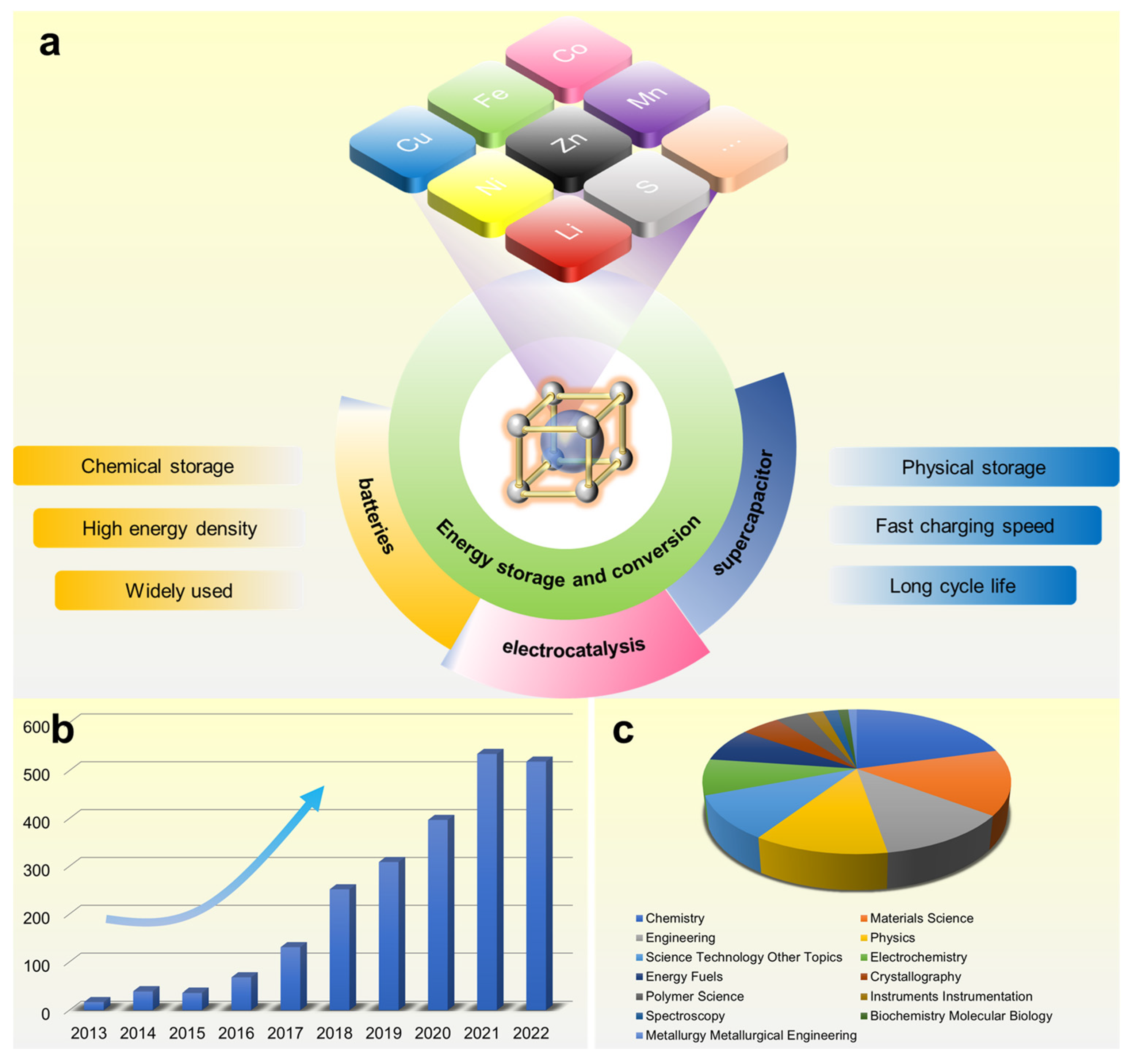
:1. Introduction
2. Synthesis
2.1. Synthesis of Conductive MOFs
2.1.1. Hydrothermal Method

2.1.2. Solvothermal Method
2.1.3. Interfacial Method
2.1.4. Other Methods
2.2. Characterization of c-MOFs
3. Application
3.1. Supercapacitor
3.2. Batteries
3.2.1. Lithium-Based Batteries
3.2.2. Sodium-Ion Batteries
3.2.3. Zinc-Based Batteries
3.3. Electrocatalysis

4. Conclusions and Outlook
- The application of c-MOF in electrocatalysts is a hot topic in the field. At present, however, its performance cannot be compared with that of precious metal catalysts [152];
- It is important to explain the relationship between the active center of c-MOF and the potential generated by the electrode during ion insertion and extraction [159];
Author Contributions
Funding
Data Availability Statement
Acknowledgments
Conflicts of Interest
References
- Ze-Hui, L.; Mei-Juan, T.; Yuan-Hao, Z.; Yu-Yang, L.; Qiu-Shi, J.; Ming-Jie, L. Application of Conductive Metal Organic Frameworks in Supercapacitors. J. Inorg. Mater. 2020, 35, 433–780. [Google Scholar] [CrossRef]
- Choi, C.; Ashby, D.S.; Butts, D.M.; DeBlock, R.H.; Wei, Q.; Lau, J.; Dunn, B. Achieving High Energy Density and High Power Density with Pseudocapacitive Materials. Nat. Rev. Mater. 2019, 5, 5–19. [Google Scholar] [CrossRef]
- Gund, G.S.; Dubal, D.P.; Patil, B.H.; Shinde, S.S.; Lokhande, C.D. Enhanced Activity of Chemically Synthesized Hybrid Graphene oxide/Mn3O4 Composite for high Performance Supercapacitors. Electrochimica Acta 2013, 92, 205–215. [Google Scholar] [CrossRef]
- Dubal, D.P.; Kim, J.G.; Kim, Y.; Holze, R.; Kim, W.B. Demonstrating the Highest Supercapacitive Performance of Branched MnO2 Nanorods Grown Directly on Flexible Substrates using Controlled Chemistry at Ambient Temperature. Energy Technol. 2013, 1, 125–130. [Google Scholar] [CrossRef]
- Dubal, D.P.; Holze, R. Self-Assembly of Stacked Layers of Mn3O4 Nanosheets Using a Scalable Chemical Strategy for Enhanced, Flexible, Electrochemical Energy Storage. J. Power Sources 2013, 238, 274–282. [Google Scholar] [CrossRef]
- Snook, G.A.; Kao, P.; Best, A.S. Conducting-Polymer-Based Supercapacitor Devices and Electrodes. J. Power Sources 2011, 196, 1–12. [Google Scholar] [CrossRef]
- Ramya, R.; Sivasubramanian, R.; Sangaranarayanan, M. Conducting Polymers-Based Electrochemical Supercapacitors—Progress and Prospects. Electrochim. Acta 2013, 101, 109–129. [Google Scholar] [CrossRef]
- Wang, Y.; Foo, C.Y.; Hoo, T.K.; Ng, M.; Lin, J. Designed Smart System of the Sandwiched and Concentric Architecture of RuO2/C/RuO2for High Performance in Electrochemical Energy Storage. Chem. A Eur. J. 2010, 16, 3598–3603. [Google Scholar] [CrossRef]
- Wang, D.-W.; Li, F.; Liu, M.; Lu, G.Q.; Cheng, H.-M. 3D Aperiodic Hierarchical Porous Graphitic Carbon Material for High-Rate Electrochemical Capacitive Energy Storage. Angew. Chem. Int. Ed. 2008, 47, 373–376. [Google Scholar] [CrossRef]
- Zhang, L.L.; Zhao, X.S. Carbon-based materials as supercapacitor electrodes. Chem. Soc. Rev. 2009, 38, 2520–2531. [Google Scholar] [CrossRef]
- Salunkhe, R.R.; Kaneti, Y.V.; Yamauchi, Y. Metal–Organic Framework-Derived Nanoporous Metal Oxides toward Supercapacitor Applications: Progress and Prospects. ACS Nano 2017, 11, 5293–5308. [Google Scholar] [CrossRef] [PubMed]
- Luo, S.; Zhao, J.; Zou, J.; He, Z.; Xu, C.; Liu, F.; Huang, Y.; Dong, L.; Wang, L.; Zhang, H. Self-Standing Polypyrrole/Black Phosphorus Laminated Film: Promising Electrode for Flexible Supercapacitor with Enhanced Capacitance and Cycling Stability. ACS Appl. Mater. Interfaces 2018, 10, 3538–3548. [Google Scholar] [CrossRef] [PubMed]
- Guo, X.; Bai, N.; Tian, Y.; Gai, L. Free-Standing Reduced Graphene Oxide/Polypyrrole Films with Enhanced Electrochemical Performance for Flexible Supercapacitors. J. Power Sources 2018, 408, 51–57. [Google Scholar] [CrossRef]
- Wang, X.; Mathis, T.S.; Li, K.; Lin, Z.; Vlcek, L.; Torita, T.; Osti, N.C.; Hatter, C.; Urbankowski, P.; Sarycheva, A.; et al. Influences from Solvents on Charge Storage in Titanium Carbide MXenes. Nat. Energy 2019, 4, 241–248. [Google Scholar] [CrossRef]
- Augustyn, V.; Simon, P.; Dunn, B. Pseudocapacitive Oxide Materials for High-Rate Electrochemical Energy Storage. Energy Environ. Sci. 2014, 7, 1597–1614. [Google Scholar] [CrossRef]
- Yan, J.; Liu, T.; Liu, X.; Yan, Y.; Huang, Y. Metal-Organic Framework-Based Materials for Flexible Supercapacitor Application. Co-ord. Chem. Rev. 2022, 452, 214300. [Google Scholar] [CrossRef]
- Niu, L.; Wu, T.; Chen, M.; Yang, L.; Yang, J.; Wang, Z.; Kornyshev, A.A.; Jiang, H.; Bi, S.; Feng, G. Conductive Metal–Organic Frameworks for Supercapacitors. Adv. Mater. 2022, 34, e2200999. [Google Scholar] [CrossRef]
- Li, P.; Wang, B. Recent Development and Application of Conductive MOFs. Isr. J. Chem. 2018, 58, 1010–1018. [Google Scholar] [CrossRef]
- Furukawa, H.; Cordova, K.E.; O’Keeffe, M.; Yaghi, O.M. The Chemistry and Applications of Metal-Organic Frameworks. Science 2013, 341, 1230444. [Google Scholar] [CrossRef]
- Usman, M.; Haider, G.; Mendiratta, S.; Luo, T.-T.; Chen, Y.-F.; Lu, K.-L. Continuous Broadband Emission from a Metal–Organic Framework as a Human-Friendly White Light Source. J. Mater. Chem. C 2016, 4, 4728–4732. [Google Scholar] [CrossRef]
- Duan, T.-W.; Yan, B. Hybrids Based on Lanthanide Ions Activated Yttrium Metal–Organic Frameworks: Functional Assembly, Polymer Film Preparation and Luminescence Tuning. J. Mater. Chem. C 2014, 2, 5098–5104. [Google Scholar] [CrossRef]
- Li, J.-R.; Sculley, J.; Zhou, H.-C. Metal–Organic Frameworks for Separations. Chem. Rev. 2011, 112, 869–932. [Google Scholar] [CrossRef] [PubMed]
- Li, B.; Hu, N.; Su, Y.; Yang, Z.; Shao, F.; Li, G.; Zhang, C.; Zhang, Y. Direct Inkjet Printing of Aqueous Inks to Flexible All-Solid-State Graphene Hybrid Micro-Supercapacitors. ACS Appl. Mater. Interfaces 2019, 11, 46044–46053. [Google Scholar] [CrossRef] [PubMed]
- Wang, K.B.; Xun, Q.; Zhang, Q. Recent Progress in Metal-Organic Frameworks as Active Materials for Supercapacitors. Energy Chem. 2020, 2, 100025. [Google Scholar] [CrossRef]
- Hong, M.; Zhou, C.; Xu, S.; Ye, X.; Yang, Z.; Zhang, L.; Zhou, Z.; Hu, N.; Zhang, Y. Bi-Metal Organic Framework Nanosheets Assembled on Nickel Wire Films for Volumetric-Energy-Dense Supercapacitors. J. Power Sources 2019, 423, 80–89. [Google Scholar] [CrossRef]
- Chaudhari, S.; Sharma, Y.; Archana, P.S.; Jose, R.; Ramakrishna, S.; Mhaisalkar, S.; Srinivasan, M. Electrospun Polyaniline Nanofibers Web Electrodes for Supercapacitors. J. Appl. Polym. Sci. 2012, 129, 1660–1668. [Google Scholar] [CrossRef]
- Getman, R.B.; Bae, Y.-S.; Wilmer, C.E.; Snurr, R.Q. Review and Analysis of Molecular Simulations of Methane, Hydrogen, and Acetylene Storage in Metal–Organic Frameworks. Chem. Rev. 2012, 112, 703–723. [Google Scholar] [CrossRef] [PubMed]
- Rowsell, J.L.C.; Yaghi, O.M. Microporous Materials Strategies for Hydrogen Storage in Metal-Organic Frameworks. Angew. Chem. Int. Ed. 2005, 44, 4670–4679. [Google Scholar] [CrossRef] [PubMed]
- Ajdari, F.B.; Kowsari, E.; Shahrak, M.N.; Ehsani, A.; Kiaei, Z.; Torkzaban, H.; Ershadi, M.; Eshkalak, S.K.; Haddadi-Asl, V.; Chinnappan, A.; et al. A review on the Field Patents and Recent Developments Over the Application of Metal Organic Frameworks (MOFs) in Supercapacitors. Coord. Chem. Rev. 2020, 422, 213441. [Google Scholar] [CrossRef]
- Naseri, M.; Fotouhi, L.; Ehsani, A.; Dehghanpour, S. Facile Electrosynthesis of Nano Flower Like Metal-Organic Framework and its Nanocomposite with Conjugated Polymer as a Novel and Hybrid Electrode Material for Highly Capacitive Pseudocapacitors. J. Colloid Interface Sci. 2016, 484, 314–319. [Google Scholar] [CrossRef]
- Rahmanifar, M.S.; Hesari, H.; Noori, A.; Masoomi, M.Y.; Morsali, A.; Mousavi, M.F. A Dual Ni/Co-MOF-Reduced Graphene Oxide Nanocomposite as a High Performance Supercapacitor Electrode Material. Electrochim. Acta 2018, 275, 76–86. [Google Scholar] [CrossRef]
- Shen, D.; Pang, A.; Li, Y.; Dou, J.; Wei, M. Metal–Organic Frameworks at Interfaces of Hybrid Perovskite Solar Cells for Enhanced Photovoltaic Properties. Chem. Commun. 2018, 54, 1253–1256. [Google Scholar] [CrossRef] [PubMed]
- He, H.; Hashemi, L.; Hu, M.-L.; Morsali, A. The role of the Counter-Ion in Metal-Organic Frameworks’ Chemistry and Applications. Coord. Chem. Rev. 2018, 376, 319–347. [Google Scholar] [CrossRef]
- Li, H.; Zhang, Z.; Huang, X.; Lan, T.; Wei, M.; Ma, T. Metal–Organic Framework Derived Hierarchical Porous TiO 2 Nanopills as a Super Stable Anode for Na-ion batteries. J. Energy Chem. 2017, 26, 667–672. [Google Scholar] [CrossRef]
- Ding, T.; Wu, J.; Chen, Z.; Lan, T.; Wei, M. Synthesis of Hierarchically Mesoporous TiO2 Spheres via an Emulsion Polymerization Route for Superior Lithium-Ion Batteries. J. Electroanal. Chem. 2018, 818, 1–9. [Google Scholar] [CrossRef]
- Ryu, H.S.; Park, J.W.; Park, J.; Ahn, J.-P.; Kim, K.-W.; Ahn, J.-H.; Nam, T.-H.; Wang, G.; Ahn, H.-J. High Capacity Cathode Materials for Li–S Batteries. J. Mater. Chem. A 2013, 1, 1573–1578. [Google Scholar] [CrossRef]
- Ke, F.-S.; Wu, Y.-S.; Deng, H. Metal-Organic Frameworks for Lithium Ion Batteries and Supercapacitors. J. Solid State Chem. 2015, 223, 109–121. [Google Scholar] [CrossRef]
- Zheng, S.; Li, Q.; Xue, H.; Pang, H.; Xu, Q. A highly Alkaline-Stable Metal Oxide@Metal–Organic Framework Composite for High-Performance Electrochemical Energy Storage. Natl. Sci. Rev. 2019, 7, 305–314. [Google Scholar] [CrossRef]
- Li, X.; Yang, X.; Xue, H.; Pang, H.; Xu, Q. Metal–Organic Frameworks as a Platform for Clean Energy Applications. EnergyChem 2020, 2, 100027. [Google Scholar] [CrossRef]
- Liang, Z.; Zhao, R.; Qiu, T.; Zou, R.; Xu, Q. Metal-Organic Framework-Derived Materials for Electrochemical Energy Applications. EnergyChem 2019, 1, 100001. [Google Scholar] [CrossRef]
- Li, C.; Zhang, L.; Chen, J.; Li, X.; Sun, J.; Zhu, J.; Wang, X.; Fu, Y. Recent Development and Applications of Electrical Conductive MOFs. Nanoscale 2021, 13, 485–509. [Google Scholar] [CrossRef] [PubMed]
- Xie, L.S.; Skorupskii, G.; Dincă, M. Electrically Conductive Metal–Organic Frameworks. Chem. Rev. 2020, 120, 8536–8580. [Google Scholar] [CrossRef] [PubMed]
- Ding, M.; Cai, X.; Jiang, H.-L. Improving MOF Stability: Approaches and Applications. Chem. Sci. 2019, 10, 10209–10230. [Google Scholar] [CrossRef]
- Shang, S.; Du, C.; Liu, Y.; Liu, M.; Wang, X.; Gao, W.; Zou, Y.; Dong, J.; Liu, Y.; Chen, J. Publisher Correction: A One-Dimensional Conductive Metal-Organic Framework with Extended π-d Conjugated Nanoribbon Layers. Nat. Commun. 2023, 14, 190. [Google Scholar] [CrossRef] [PubMed]
- Hmadeh, M.; Liu, Z.; Gándara, F.; Furukawa, H.; Wan, S.; Augustyn, V.; Chang, R.; Liao, L.; Zhou, F.; Perre, E.; et al. New Porous Crystals of Extended Metal-Catecholates. Chem. Mater. 2012, 24, 3511–3513. [Google Scholar] [CrossRef]
- Nam, K.W.; Park, S.S.; dos Reis, R.; Dravid, V.P.; Kim, H.; Mirkin, C.A.; Stoddart, J.F. Conductive 2D metal-Organic Framework for High-Performance Cathodes in Aqueous Rechargeable Zinc Batteries. Nat. Commun. 2019, 10, 4948. [Google Scholar] [CrossRef]
- Gu, S.; Bai, Z.; Majumder, S.; Huang, B.; Chen, G. Conductive Metal–Organic Framework with Redox Metal Center as Cathode for High Rate Performance Lithium Ion Battery. J. Power Sources 2019, 429, 22–29. [Google Scholar] [CrossRef]
- Li, W.-H.; Ding, K.; Tian, H.-R.; Yao, M.-S.; Nath, B.; Deng, W.-H.; Wang, Y.; Xu, G. Conductive Metal-Organic Framework Nanowire Array Electrodes for High-Performance Solid-State Supercapacitors. Adv. Funct. Mater. 2017, 27, 1702067. [Google Scholar] [CrossRef]
- Park, C.; Baek, J.W.; Shin, E.; Kim, I.-D. Two-Dimensional Electrically Conductive Metal–Organic Frameworks as Chemiresistive Sensors. ACS Nanosci. Au 2023, 3, 353–374. [Google Scholar] [CrossRef]
- Chen, H.; Xiao, Y.; Chen, C.; Yang, J.; Gao, C.; Chen, Y.; Wu, J.; Shen, Y.; Zhang, W.; Li, S.; et al. Conductive MOF-Modified Separator for Mitigating the Shuttle Effect of Lithium–Sulfur Battery through a Filtration Method. ACS Appl. Mater. Interfaces 2019, 11, 11459–11465. [Google Scholar] [CrossRef]
- Cai, D.; Lu, M.; Li, L.; Cao, J.; Chen, D.; Tu, H.; Li, J.; Han, W. A Highly Conductive MOF of Graphene Analogue Ni 3 (HITP) 2 as a Sulfur Host for High-Performance Lithium–Sulfur Batteries. Small 2019, 15, e1902605. [Google Scholar] [CrossRef] [PubMed]
- Park, J.; Lee, M.; Feng, D.; Huang, Z.; Hinckley, A.C.; Yakovenko, A.; Zou, X.; Cui, Y.; Bao, Z. Stabilization of Hexaaminobenzene in a 2D Conductive Metal–Organic Framework for High Power Sodium Storage. J. Am. Chem. Soc. 2018, 140, 10315–10323. [Google Scholar] [CrossRef] [PubMed]
- Dong, S.; Wu, L.; Xue, M.; Li, Z.; Xiao, D.; Xu, C.; Shen, L.; Zhang, X. Conductive Metal–Organic Framework for High Energy Sodium-Ion Hybrid Capacitors. ACS Appl. Energy Mater. 2021, 4, 1568–1574. [Google Scholar] [CrossRef]
- Sheberla, D.; Sun, L.; Blood-Forsythe, M.A.; Er, S.; Wade, C.R.; Brozek, C.K.; Aspuru-Guzik, A.; Dincǎ, M. High Electrical Conductivity in Ni3(2,3,6,7,10,11- Hexaiminotriphenylene)2, a Semiconducting Metal-Organic Graphene Analogue. J. Am. Chem. Soc. 2014, 136, 8859–8862. [Google Scholar] [CrossRef]
- Wu, H.; Zhang, W.; Kandambeth, S.; Shekhah, O.; Eddaoudi, M.; Alshareef, H.N. Conductive Metal–Organic Frameworks Selectively Grown on Laser-Scribed Graphene for Electrochemical Microsupercapacitors. Adv. Energy Mater. 2019, 9, 1900482. [Google Scholar] [CrossRef]
- Wu, Z.; Adekoya, D.; Huang, X.; Kiefel, M.J.; Xie, J.; Xu, W.; Zhang, Q.; Zhu, D.; Zhang, S. Highly Conductive Two-Dimensional Metal–Organic Frameworks for Resilient Lithium Storage with Superb Rate Capability. ACS Nano 2020, 14, 12016–12026. [Google Scholar] [CrossRef] [PubMed]
- Wang, S.; Huang, F.; Zhang, Z.; Cai, W.; Jie, Y.; Wang, S.; Yan, P.; Jiao, S.; Cao, R. Conductive Metal-Organic Frameworks Promoting Polysulfides Transformation in Lithium-Sulfur Batteries. J. Energy Chem. 2021, 63, 336–343. [Google Scholar] [CrossRef]
- Guo, J.; Wu, L.; Ye, Y.-X.; Zhu, F.; Xu, J.; Ouyang, G. Two-Dimensional Conductive Metal–Organic Framework for Small-Molecule Sensing in Aqueous Solution. Anal. Chem. 2023, 95, 13412–13416. [Google Scholar] [CrossRef]
- Wang, H.; Zhu, C.; Wu, M.; Zheng, F.; Gao, Y.; Niu, H. Synthesis of a Novel Double-Ligand Nickel Conductive Metal–Organic Framework Material and its Electrochemical Characterization for Supercapacitors. J. Mater. Sci. 2020, 56, 2517–2527. [Google Scholar] [CrossRef]
- Jeon, M.; Kim, M.; Lee, J.-S.; Kim, H.; Choi, S.-J.; Moon, H.R.; Kim, J. Computational Prediction of Stacking Mode in Conductive Two-Dimensional Metal–Organic Frameworks: An Exploration of Chemical and Electrical Property Changes. ACS Sensors 2023, 8, 3068–3075. [Google Scholar] [CrossRef]
- Van Vleet, M.J.; Weng, T.; Li, X.; Schmidt, J.R. In Situ, Time-Resolved, and Mechanistic Studies of Metal-Organic Framework Nucleation and Growth. Chem. Rev. 2018, 118, 3681–3721. [Google Scholar] [CrossRef]
- Takaishi, S.; Hosoda, M.; Kajiwara, T.; Miyasaka, H.; Yamashita, M.; Nakanishi, Y.; Kitagawa, Y.; Yamaguchi, K.; Kobayashi, A.; Kitagawa, H. Electroconductive Porous Coordination Polymer Cu[Cu(pdt)2] Composed of Donor and Acceptor Building Units. Inorg. Chem. 2009, 48, 9048–9050. [Google Scholar] [CrossRef] [PubMed]
- Iqbal, M.Z.; Shaheen, M.; Khan, M.W.; Siddique, S.; Farid, S.; Aftab, S.; Wabaidur, S.M. Elucidating d-π Conjugated Two-Dimensional 2,3,6,7,10,11-Hexahydroxytriphenylene based Conductive Metal-Organic Framework for Hybrid Supercapacitors. J. Electroanal. Chem. 2023, 943, 117564. [Google Scholar] [CrossRef]
- Sirijaraensre, J. Sensing properties of 2D conductive M3(HITP)2 MOFs toward SO2 gas: A Theoretical Study. Chem. Pap. 2023, 77, 6053–6068. [Google Scholar] [CrossRef]
- Wrogemann, J.M.; Lüther, M.J.; Bärmann, P.; Lounasvuori, M.; Javed, A.; Tiemann, M.; Golnak, R.; Xiao, J.; Petit, T.; Placke, T.; et al. Overcoming Diffusion Limitation of Faradaic Processes: Property-Performance Relationships of 2D Conductive Metal-Organic Framework Cu3(HHTP)2 for Reversible Lithium-Ion Storage. Angew. Chem. Int. Ed. 2023, 62, e202303111. [Google Scholar] [CrossRef] [PubMed]
- Iqbal, M.Z.; Shaheen, M.; Khan, M.W.; Siddique, S.; Farid, S.; Aftab, S.; Wabaidur, S.M. The rise of 2D Conductive Metal-Organic Framework: Cu3(HHTP)2 d-π MOF for Integrated Battery-Supercapacitor Hybrids. Mater. Today Sustain. 2023, 22, 100331. [Google Scholar] [CrossRef]
- Zhao, W.; Chen, T.; Wang, W.; Jin, B.; Peng, J.; Bi, S.; Jiang, M.; Liu, S.; Zhao, Q.; Huang, W. Conductive Ni3(HITP)2 MOFs thin Films for Flexible Transparent Supercapacitors with High Rate Capability. Sci. Bull. 2020, 65, 1803–1811. [Google Scholar] [CrossRef] [PubMed]
- Zang, Y.; Pei, F.; Huang, J.; Fu, Z.; Xu, G.; Fang, X. Large-Area Preparation of Crack-Free Crystalline Microporous Conductive Membrane to Upgrade High Energy Lithium–Sulfur Batteries. Adv. Energy Mater. 2018, 8, 1802052. [Google Scholar] [CrossRef]
- Yan, J.; Cui, Y.; Xie, M.; Yang, G.; Bin, D.; Li, D. Immobilizing Redox-Active Tricycloquinazoline into a 2D Conductive Metal–Organic Framework for Lithium Storage. Angew. Chem. 2021, 133, 24672–24677. [Google Scholar] [CrossRef]
- Gittins, J.W.; Balhatchet, C.J.; Chen, Y.; Liu, C.; Madden, D.G.; Britto, S.; Golomb, M.J.; Walsh, A.; Fairen-Jimenez, D.; Dutton, S.E.; et al. Insights Into the Electric Double-Layer Capacitance of Two-Dimensional Electrically Conductive Metal–Organic Frameworks. J. Mater. Chem. A 2021, 9, 16006–16015. [Google Scholar] [CrossRef]
- Contreras-Pereda, N.; Rodríguez-San-Miguel, D.; Franco, C.; Sevim, S.; Vale, J.P.; Solano, E.; Fong, W.; Del Giudice, A.; Galantini, L.; Pfattner, R.; et al. 2D Materials: Synthesis of 2D Porous Crystalline Materials in Simulated Microgravity (Adv. Mater. 30/2021). Adv. Mater. 2021, 33, 2170231. [Google Scholar] [CrossRef]
- Wang, M.; Dong, R.; Feng, X. Two-Dimensional Conjugated Metal–Organic Frameworks (2D c-MOFs): Chemistry and Function for MOFtronics. Chem. Soc. Rev. 2021, 50, 2764–2793. [Google Scholar] [CrossRef]
- Wu, G.; Huang, J.; Zang, Y.; He, J.; Xu, G. Porous Field-Effect Transistors Based on a Semiconductive Metal–Organic Framework. J. Am. Chem. Soc. 2017, 139, 1360–1363. [Google Scholar] [CrossRef] [PubMed]
- Zhong, Y.; Zhang, X.; He, Y.; Peng, H.; Wang, G.; Xin, G. Simultaneously Armored and Active Graphene for Transparent and Flexible Supercapacitors. Adv. Funct. Mater. 2018, 28, 1801998. [Google Scholar] [CrossRef]
- Peng, H.; Zhong, Y.; Zhang, X.; He, Y.; Wang, G. Percolating Film of Pillared Graphene Layer Integrated with Silver Nanowire Network for Transparent and Flexible Supercapacitors. Langmuir 2018, 34, 15245–15252. [Google Scholar] [CrossRef] [PubMed]
- Wang, G.-F.; Qin, H.; Gao, X.; Cao, Y.; Wang, W.; Wang, F.-C.; Wu, H.-A.; Cong, H.-P.; Yu, S.-H. Graphene Thin Films by Noncovalent-Interaction-Driven Assembly of Graphene Monolayers for Flexible Supercapacitors. Chem 2018, 4, 896–910. [Google Scholar] [CrossRef]
- Majidi, L.; Ahmadiparidari, A.; Shan, N.; Singh, S.K.; Zhang, C.; Huang, Z.; Rastegar, S.; Kumar, K.; Hemmat, Z.; Ngo, A.T.; et al. Nanostructured Conductive Metal Organic Frameworks for Sustainable Low Charge Overpotentials in Li–Air Batteries. Small 2022, 18, 2102902. [Google Scholar] [CrossRef] [PubMed]
- Kon, K.; Uchida, K.; Fuku, K.; Yamanaka, S.; Wu, B.; Yamazui, D.; Iguchi, H.; Kobayashi, H.; Gambe, Y.; Honma, I.; et al. Electron-Conductive Metal-Organic Framework, Fe(Dhbq)(Dhbq = 2,5-Dihydroxy-1,4-Benzoquinone): Coexistence of Mi-croporosity and Solid-State Redox Activity. ACS Appl. Mater. Interfaces 2021, 13, 38188–38193. [Google Scholar] [CrossRef] [PubMed]
- Zhou, S.; Kong, X.; Zheng, B.; Huo, F.; Strømme, M.; Xu, C. Cellulose Nanofiber @ Conductive Metal–Organic Frameworks for High-Performance Flexible Supercapacitors. ACS Nano 2019, 13, 9578–9586. [Google Scholar] [CrossRef] [PubMed]
- Kambe, T.; Sakamoto, R.; Hoshiko, K.; Takada, K.; Miyachi, M.; Ryu, J.-H.; Sasaki, S.; Kim, J.; Nakazato, K.; Takata, M.; et al. π-Conjugated Nickel Bis(dithiolene) Complex Nanosheet. J. Am. Chem. Soc. 2013, 135, 2462–2465. [Google Scholar] [CrossRef] [PubMed]
- Rubio-Giménez, V.; Galbiati, M.; Castells-Gil, J.; Almora-Barrios, N.; Navarro-Sánchez, J.; Escorcia-Ariza, G.; Mattera, M.; Arnold, T.; Rawle, J.; Tatay, S.; et al. Bottom-Up Fabrication of Semiconductive Metal–Organic Framework Ultrathin Films. Adv. Mater. 2018, 30, 1704291. [Google Scholar] [CrossRef] [PubMed]
- Du, X.; Zhang, J.; Wang, H.; Huang, Z.; Guo, A.; Zhao, L.; Niu, Y.; Li, X.; Wu, B.; Liu, Y. Solid–Solid Interface Growth of Conductive Metal–Organic Framework Nanowire Arrays and their Supercapacitor Application. Mater. Chem. Front. 2019, 4, 243–251. [Google Scholar] [CrossRef]
- Guo, J.; Liu, J.; Ma, W.; Sang, Z.; Yin, L.; Zhang, X.; Chen, H.; Liang, J.; Yang, D. Vanadium Oxide Intercalated with Conductive Metal–Organic Frameworks with Dual Energy-Storage Mechanism for High Capacity and High-Rate Capability Zn Ion Storage. Adv. Funct. Mater. 2023, 33, 2302659. [Google Scholar] [CrossRef]
- Li, P.; Shi, X.; Wu, Y.; Song, M.; Lai, Y.; Yu, H.; Lu, G. Cathodic synthesis of a Cu-Catecholate Metal–Organic Framework. CrystEngComm 2021, 23, 1828–1835. [Google Scholar] [CrossRef]
- Choi, J.Y.; Park, J. Enhancing Electrical Conductivity of Semiconducting MOFs via Defect Healing. ACS Appl. Electron. Mater. 2021, 3, 4197–4202. [Google Scholar] [CrossRef]
- Varoon, K.; Zhang, X.; Elyassi, B.; Brewer, D.D.; Gettel, M.; Kumar, S.; Lee, J.A.; Maheshwari, S.; Mittal, A.; Sung, C.Y.; et al. Dispersible Exfoliated Zeolite Nanosheets and Their Appli-cation as a Selective Membrane. Science 2011, 334, 72–75. [Google Scholar] [CrossRef] [PubMed]
- Iqbal, R.; Sultan, M.Q.; Hussain, S.; Hamza, M.; Tariq, A.; Akbar, M.B.; Ma, Y.; Zhi, L. The Different Roles of Cobalt and Manganese in Metal-Organic Frameworks for Supercapacitors. Adv. Mater. Technol. 2021, 6, 2000941. [Google Scholar] [CrossRef]
- Guo, T.; Ding, Y.; Xu, C.; Bai, W.; Pan, S.; Liu, M.; Bi, M.; Sun, J.; Ouyang, X.; Wang, X.; et al. High Crystallinity 2D π–d Conjugated Conductive Metal–Organic Framework for Boosting Polysulfide Conversion in Lithium–Sulfur Batteries. Adv. Sci. 2023, 10, e2302518. [Google Scholar] [CrossRef]
- Jia, H.; Lu, S.; Shin, S.H.R.; Sushko, M.L.; Tao, X.; Hummel, M.; Thallapally, P.K.; Liu, J.; Gu, Z. In Situ Anodic Electrodeposition of Two-Dimensional Conductive Metal-Organic Framework@Nickel Foam for high-Performance Flexible Supercapacitor. J. Power Sources 2022, 526, 231163. [Google Scholar] [CrossRef]
- Sang, Z.; Liu, J.; Zhang, X.; Yin, L.; Hou, F.; Liang, J. One-Dimensional π–d Conjugated Conductive Metal–Organic Framework with Dual Redox-Active Sites for High-Capacity and Durable Cathodes for Aqueous Zinc Batteries. ACS Nano 2023, 17, 3077–3087. [Google Scholar] [CrossRef]
- Chen, X.; Dong, J.; Chi, K.; Wang, L.; Xiao, F.; Wang, S.; Zhao, Y.; Liu, Y. Electrically Conductive Metal–Organic Framework Thin Film-Based On-Chip Micro-Biosensor: A Platform to Unravel Surface Morphology-Dependent Biosensing. Adv. Funct. Mater. 2021, 31, 2102855. [Google Scholar] [CrossRef]
- Chen, X.; Lu, Y.; Dong, J.; Ma, L.; Yi, Z.; Wang, Y.; Wang, L.; Wang, S.; Zhao, Y.; Huang, J.; et al. Ultrafast In Situ Synthesis of Large-Area Conductive Metal–Organic Frameworks on Substrates for Flexible Chemiresistive Sensing. ACS Appl. Mater. Interfaces 2020, 12, 57235–57244. [Google Scholar] [CrossRef] [PubMed]
- Feng, D.; Lei, T.; Lukatskaya, M.R.; Park, J.; Huang, Z.; Lee, M.; Shaw, L.; Chen, S.; Yakovenko, A.A.; Kulkarni, A.; et al. Robust and Conductive Two-Dimensional Metal−Organic Frameworks with Exceptionally High Volumetric and areal Capacitance. Nat. Energy 2018, 3, 30–36. [Google Scholar] [CrossRef]
- Park, J.; Hinckley, A.C.; Huang, Z.; Chen, G.; Yakovenko, A.A.; Zou, X.; Bao, Z. High Thermopower in a Zn-Based 3D Semi-conductive Metal-Organic Framework. J. Am. Chem. Soc. 2020, 142, 20531–20535. [Google Scholar] [CrossRef] [PubMed]
- Sun, L.; Liao, B.; Sheberla, D.; Kraemer, D.; Zhou, J.; Stach, E.A.; Zakharov, D.; Stavila, V.; Talin, A.A.; Ge, Y.; et al. A Microporous and Naturally Nanostructured Thermoelectric Metal-Organic Framework with Ultralow Thermal Conductivity. Joule 2017, 1, 168–177. [Google Scholar] [CrossRef]
- Yao, M.-S.; Lv, X.-J.; Fu, Z.-H.; Li, W.-H.; Deng, W.-H.; Wu, G.-D.; Xu, G. Inside Cover: Layer-by-Layer Assembled Conductive Metal-Organic Framework Nanofilms for Room-Temperature Chemiresistive Sensing (Angew. Chem. Int. Ed. 52/2017). Angew. Chem. Int. Ed. 2017, 56, 16418. [Google Scholar] [CrossRef]
- Lai, X.; Peng, J.; Cheng, Q.; Tomsia, A.P.; Zhao, G.; Liu, L.; Zou, G.; Song, Y.; Jiang, L.; Li, M. Cover Picture: Bioinspired Color Switchable Photonic Crystal Silicone Elastomer Kirigami (Angew. Chem. Int. Ed. 26/2021). Angew. Chem. Int. Ed. 2021, 60, 14197. [Google Scholar] [CrossRef]
- Meng, Z.; Aykanat, A.; Mirica, K.A. Welding Metallophthalocyanines into Bimetallic Molecular Meshes for Ultrasensitive, Low-Power Chemiresistive Detection of Gases. J. Am. Chem. Soc. 2018, 141, 2046–2053. [Google Scholar] [CrossRef]
- Howarth, A.J.; Peters, A.W.; Vermeulen, N.A.; Wang, T.C.; Hupp, J.T.; Farha, O.K. Best Practices for the Synthesis, Activation, and Characterization of Metal–Organic Frameworks. Chem. Mater. 2017, 29, 26–39. [Google Scholar] [CrossRef]
- Saeki, A.; Koizumi, Y.; Aida, T.; Seki, S. Comprehensive Approach to Intrinsic Charge Carrier Mobility in Conjugated Organic Molecules, Macromolecules, and Supramolecular Architectures. Accounts Chem. Res. 2012, 45, 1193–1202. [Google Scholar] [CrossRef] [PubMed]
- Givaja, G.; Amo-Ochoa, P.; Gomez-Garcia, C.J.; Zamora, F. Electrical conductive coordination polymers. Chem. Soc. Rev. 2012, 41, 115–147. [Google Scholar] [CrossRef]
- Wilmer, C.E.; Leaf, M.; Lee, C.Y.; Farha, O.K.; Hauser, B.G.; Hupp, J.T.; Snurr, R.Q. Large-Scale Screening of Hypothetical Metal–organic frameworks. Nat. Chem. 2012, 4, 83–89. [Google Scholar] [CrossRef] [PubMed]
- Yan, Y.; Lin, X.; Ge, J.; Li, X. Conductive Metal-Organic Frameworks with Wheel-Shaped Metallomacrocycle Subunits as High-Performance Supercapacitor Electrodes. Chem. Eng. J. 2023, 468, 143739. [Google Scholar] [CrossRef]
- Liu, P.; Yan, J.; Huang, H.; Song, W. Cu/Co bimetallic conductive MOFs: Electronic Modulation for Enhanced Nitrate Reduction to Ammonia. Chem. Eng. J. 2023, 466, 143134. [Google Scholar] [CrossRef]
- Wang, T.C.; Bury, W.; Gómez-Gualdrón, D.A.; Vermeulen, N.A.; Mondloch, J.E.; Deria, P.; Zhang, K.; Moghadam, P.Z.; Sarjeant, A.A.; Snurr, R.Q.; et al. Ultrahigh Surface Area Zirconium MOFs and Insights into the Applicability of the BET Theory. J. Am. Chem. Soc. 2015, 137, 3585–3591. [Google Scholar] [CrossRef] [PubMed]
- Gómez-Gualdrón, D.A.; Moghadam, P.Z.; Hupp, J.T.; Farha, O.K.; Snurr, R.Q. Application of Consistency Criteria to Calculate BET Areas of Micro- and Mesoporous Metal–Organic Frameworks. J. Am. Chem. Soc. 2016, 138, 215–224. [Google Scholar] [CrossRef]
- Sun, X.; Yan, X.; Song, K.; Zhang, T.; Yang, Z.; Su, X.; Chen, W.; Chen, L. A Pyrazine-Based 2D Conductive Metal-Organic Framework for Efficient Lithium Storage†. Chin. J. Chem. 2023, 41, 1691–1696. [Google Scholar] [CrossRef]
- Liu, J.; Zhou, Y.; Xie, Z.; Li, Y.; Liu, Y.; Sun, J.; Ma, Y.; Terasaki, O.; Chen, L. Conjugated Copper–Catecholate Framework Electrodes for Efficient Energy Storage. Angew. Chem. Int. Ed. 2019, 59, 1081–1086. [Google Scholar] [CrossRef]
- Wu, T.; Ma, Z.; He, Y.; Wu, X.; Tang, B.; Yu, Z.; Wu, G.; Chen, S.; Bao, N. A Covalent Black Phosphorus/Metal–Organic Framework Hetero-nanostructure for High-Performance Flexible Supercapacitors. Angew. Chem. Int. Ed. 2021, 60, 10366–10374. [Google Scholar] [CrossRef] [PubMed]
- Xia, Z.; Jia, X.; Ge, X.; Ren, C.; Yang, Q.; Hu, J.; Chen, Z.; Han, J.; Xie, G.; Chen, S.; et al. Tailoring Electronic Structure and Size of Ultrastable Metalated Metal–Organic Frameworks with Enhanced Electroconductivity for High-Performance Supercapacitors. Angew. Chem. 2021, 133, 10316–10326. [Google Scholar] [CrossRef]
- Choi, J.Y.; Wang, M.; Check, B.; Stodolka, M.; Tayman, K.; Sharma, S.; Park, J. Linker-Based Bandgap Tuning in Conductive MOF Solid Solutions. Small 2023, 19, e2206988. [Google Scholar] [CrossRef] [PubMed]
- Vukotic, V.N.; Harris, K.J.; Zhu, K.; Schurko, R.W.; Loeb, S.J. Metal–Organic Frameworks with Dynamic Interlocked Components. Nat. Chem. 2012, 4, 456–460. [Google Scholar] [CrossRef] [PubMed]
- Zhu, K.; O’Keefe, C.A.; Vukotic, V.N.; Schurko, R.W.; Loeb, S.J. A molecular Shuttle that Operates Inside a Metal–Organic Framework. Nat. Chem. 2015, 7, 514–519. [Google Scholar] [CrossRef] [PubMed]
- Brozek, C.K.; Michaelis, V.K.; Ong, T.-C.; Bellarosa, L.; López, N.; Griffin, R.G.; Dincă, M. Dynamic DMF Binding in MOF-5 Enables the Formation of Metastable Cobalt-Substituted MOF-5 Analogues. ACS Cent. Sci. 2015, 1, 252–260. [Google Scholar] [CrossRef] [PubMed]
- Rimoldi, M.; Nakamura, A.; Vermeulen, N.A.; Henkelis, J.J.; Blackburn, A.K.; Hupp, J.T.; Stoddart, J.F.; Farha, O.K. A metal–organic framework immobilised iridium pincer complex. Chem. Sci. 2016, 7, 4980–4984. [Google Scholar] [CrossRef] [PubMed]
- Mason, J.A.; Sumida, K.; Herm, Z.R.; Krishna, R.; Long, J.R. Evaluating Metal–Organic Frameworks for Post-Combustion Carbon Dioxide Capture via Temperature Swing Adsorption. Energy Environ. Sci. 2011, 4, 3030–3040. [Google Scholar] [CrossRef]
- Wharmby, M.T.; Henke, S.; Bennett, T.D.; Bajpe, S.R.; Schwedler, I.; Thompson, S.P.; Gozzo, F.; Simoncic, P.; Mellot-Draznieks, C.; Tao, H.; et al. Extreme Flexibility in a Zeolitic Imidazolate Framework: Porous to Dense Phase Transition in Desolvated ZIF-4. Angew. Chem. 2015, 127, 6547–6551. [Google Scholar] [CrossRef]
- Liu, D.; Huxford, R.C.; Lin, W. Phosphorescent Nanoscale Coordination Polymers as Contrast Agents for Optical Imaging. Angew. Chem. Int. Ed. 2011, 50, 3696–3700. [Google Scholar] [CrossRef]
- Fei, H.; Shin, J.; Meng, Y.S.; Adelhardt, M.; Sutter, J.; Meyer, K.; Cohen, S.M. Reusable Oxidation Catalysis Using Met-al-Monocatecholato Species in a Robust Metal-Organic Framework. J. Am. Chem. Soc. 2014, 136, 4965–4973. [Google Scholar] [CrossRef]
- Wada, K.; Sakaushi, K.; Sasaki, S.; Nishihara, H. Multielectron-Transfer-based Rechargeable Energy Storage of Two-Dimensional Coordination Frameworks with Non-Innocent Ligands. Angew. Chem. 2018, 130, 9024–9028. [Google Scholar] [CrossRef]
- Gao, G.; Zheng, F.; Pan, F.; Wang, L. Theoretical Investigation of 2D Conductive Microporous Coordination Polymers as Li–S Battery Cathode with Ultrahigh Energy Density. Adv. Energy Mater. 2018, 8, 1801823. [Google Scholar] [CrossRef]
- Zhang, M.-C.; Liu, M.-Y.; Yang, M.-X.; Liu, X.-X.; Shen, S.-Y.; Wu, J.-S.; Pei, W.-B. Copper-Cobalt Bimetallic Conductive Metal–Organic Frameworks as Bifunctional Oxygen Electrocatalyst in Alkaline and Neutral Media. J. Solid State Chem. 2023, 325, 124133. [Google Scholar] [CrossRef]
- Miner, E.M.; Fukushima, T.; Sheberla, D.; Sun, L.; Surendranath, Y.; Dincă, M. Electrochemical Oxygen Reduction Catalysed by Ni3(hexaiminotriphenylene)2. Nat. Commun. 2016, 7, 10942. [Google Scholar] [CrossRef] [PubMed]
- Sun, L.; Park, S.S.; Sheberla, D.; Dincă, M. Measuring and Reporting Electrical Conductivity in Metal–Organic Frameworks: Cd2(TTFTB) as a Case Study. J. Am. Chem. Soc. 2016, 138, 14772–14782. [Google Scholar] [CrossRef] [PubMed]
- Yin, J.; Li, N.; Liu, M.; Li, Z.; Wang, X.; Cheng, M.; Zhong, M.; Li, W.; Xu, Y.; Bu, X. Stabilizing Redox-Active Hexaazatriphenylene in a 2D Conductive Metal–Organic Framework for Improved Lithium Storage Performance. Adv. Funct. Mater. 2023, 33, 2211950. [Google Scholar] [CrossRef]
- Ohata, T.; Nomoto, A.; Watanabe, T.; Hirosawa, I.; Makita, T.; Takeya, J.; Makiura, R. Air/Liquid Interfacial Formation Process of Conductive Metal–Organic Framework Nanosheets. J. Colloid Interface Sci. 2023, 651, 769–784. [Google Scholar] [CrossRef]
- Sun, L.; Campbell, M.G.; Dincă, M. Electrically Conductive Porous Metal–Organic Frameworks. Angew. Chem. Int. Ed. 2016, 55, 3566–3579. [Google Scholar] [CrossRef]
- Dong, J.; Chen, X.; Wang, L.; Wang, S.; Zhao, Y.; Liu, Y. Electrocatalytic Microdevice Array Based on Wafer-Scale Conductive Metal-Organic Framework Thin Film for Massive Hydrogen Production. Small 2023, e2302913. [Google Scholar] [CrossRef]
- Debela, T.T.; Yang, M.C.; Hendon, C.H. Ligand-Mediated Hydrogenic Defects in Two-Dimensional Electrically Conductive Metal–Organic Frameworks. J. Am. Chem. Soc. 2023, 145, 11387–11391. [Google Scholar] [CrossRef]
- Wang, T.; Lei, J.; Wang, Y.; Pang, L.; Pan, F.; Chen, K.; Wang, H. Approaches to Enhancing Electrical Conductivity of Pristine Metal–Organic Frameworks for Supercapacitor Applications. Small 2022, 18, e2203307. [Google Scholar] [CrossRef] [PubMed]
- Nguyen, D.; Schepisi, I.; Amir, F. Extraordinary cycling stability of Ni3(HITP)2 supercapacitors fabricated by electrophoretic deposition: Cycling at 100,000 cycles. Chem. Eng. J. 2019, 378, 122150. [Google Scholar] [CrossRef]
- He, B.; Zhang, Q.; Man, P.; Zhou, Z.; Li, C.; Li, Q.; Xie, L.; Wang, X.; Pang, H.; Yao, Y. Self-Sacrificed Synthesis of Conductive Vanadium-Based Metal–Organic Framework Nanowire-Bundle Arrays as Binder-Free Cathodes for High-Rate and High-Energy-Density Wearable Zn-Ion Batteries. Nano Energy 2019, 64, 103935. [Google Scholar] [CrossRef]
- Li, C.; Zhang, Q.; Li, T.; He, B.; Man, P.; Zhu, Z.; Zhou, Z.; Wei, L.; Zhang, K.; Hong, G.; et al. Nickel Metal–Organic Framework Nanosheets as Novel Binder-Free Cathode for Advanced Fibrous Aqueous Rechargeable Ni–Zn battery. J. Mater. Chem. A 2020, 8, 3262–3269. [Google Scholar] [CrossRef]
- Dresselhaus, M.S.; Thomas, I.L. Alternative energy technologies. Nature 2001, 414, 332–337. [Google Scholar] [CrossRef] [PubMed]
- Li, G.; Yang, H.; Li, F.; Cheng, F.; Shi, W.; Chen, J.; Cheng, P. A Coordination Chemistry Approach for Lithium-Ion Batteries: The Coexistence of Metal and Ligand Redox Activities in a One-Dimensional Metal–Organic Material. Inorg. Chem. 2016, 55, 4935–4940. [Google Scholar] [CrossRef] [PubMed]
- Holland, B.T.; Blanford, C.F.; Stein, A.; Zakhidov, A.; Baughman, R.H.; Iqbal, Z.; Cui, C.; Khayrullin, I.; Liu, L.; Udod, I.; et al. Three Dimensionally Periodic Structural Assemblies on Nanometer and Longer Scales. US Patent 6,261,469, 10 September 1998. [Google Scholar]
- Guo, L.; Sun, J.; Zhang, W.; Hou, L.; Liang, L.; Liu, Y.; Yuan, C. Bottom-Up Fabrication of 1D Cu-based Conductive Metal–Organic Framework Nanowires as a High-Rate Anode towards Efficient Lithium Storage. ChemSusChem 2019, 12, 5051–5058. [Google Scholar] [CrossRef] [PubMed]
- Wu, Q.; Yao, Z.; Zhou, X.; Xu, J.; Cao, F.; Li, C. Built-In Catalysis in Confined Nanoreactors for High-Loading Li–S Batteries. ACS Nano 2020, 14, 3365–3377. [Google Scholar] [CrossRef] [PubMed]
- Ansari, Y.; Zhang, S.; Wen, B.; Fan, F.; Chiang, Y. Stabilizing Li–S Battery Through Multilayer Encapsulation of Sulfur. Adv. Energy Mater. 2019, 9, 1802213. [Google Scholar] [CrossRef]
- Hong, S.Y.; Kim, Y.; Park, Y.; Choi, A.; Choi, N.-S.; Lee, K.T. Charge Carriers in Rechargeable Batteries: Na Ions vs. Li Ions. Energy Environ. Sci. 2013, 6, 2067–2081. [Google Scholar] [CrossRef]
- Palomares, V.; Casas-Cabanas, M.; Castillo-Martínez, E.; Han, M.H.; Rojo, T. Update on Na-Based Battery Materials. A Growing Research Path. Energy Environ. Sci. 2013, 6, 2312–2337. [Google Scholar] [CrossRef]
- Li, C.; Sun, X.; Yao, Y.; Hong, G. Recent Advances of Electrically Conductive Metal-Organic Frameworks in Electrochemical Applications. Mater. Today Nano 2021, 13, 100105. [Google Scholar] [CrossRef]
- Zhou, W.; Lv, S.; Liu, X.; Li, Y.; Liu, J. A directly grown pristine Cu-CAT Metal–Organic Framework as an Anode Material for High-Energy Sodium-Ion Capacitors. Chem. Commun. 2019, 55, 11207–11210. [Google Scholar] [CrossRef] [PubMed]
- Wang, F.; Liu, Z.; Yang, C.; Zhong, H.; Nam, G.; Zhang, P.; Dong, R.; Wu, Y.; Cho, J.; Zhang, J.; et al. Fully Conjugated Phthalocyanine Copper Metal–Organic Frameworks for Sodium–Iodine Batteries with Long-Time-Cycling Durability. Adv. Mater. 2020, 32, 1905361. [Google Scholar] [CrossRef] [PubMed]
- Zhu, K.; Wu, T.; Sun, S.; Wen, Y.; Huang, K. Electrode Materials for Practical Rechargeable Aqueous Zn-Ion Batteries: Challenges and Opportunities. ChemElectroChem 2020, 7, 2714–2734. [Google Scholar] [CrossRef]
- Song, M.; Tan, H.; Chao, D.; Fan, H.J. Recent Advances in Zn-Ion Batteries. Adv. Funct. Mater. 2018, 28, 1802564. [Google Scholar] [CrossRef]
- Li, C.; Zheng, C.; Jiang, H.; Bai, S.; Jia, J. Conductive flower-like Ni-PTA-Mn as Cathode for Aqueous Zinc-Ion Batteries. J. Alloy. Compd. 2021, 882, 160587. [Google Scholar] [CrossRef]
- Chu, S.; Majumdar, A. Opportunities and Challenges for a Sustainable Energy Future. Nature 2012, 488, 294–303. [Google Scholar] [CrossRef]
- Downes, C.A.; Marinescu, S.C. Electrocatalytic Metal–Organic Frameworks for Energy Applications. ChemSusChem 2017, 10, 4374–4392. [Google Scholar] [CrossRef]
- Huang, X.; Yao, H.; Cui, Y.; Hao, W.; Zhu, J.; Xu, W.; Zhu, D. Conductive Copper Benzenehexathiol Coordination Polymer as a Hydrogen Evolution Catalyst. ACS Appl. Mater. Interfaces 2017, 9, 40752–40759. [Google Scholar] [CrossRef]
- Xing, D.; Wang, Y.; Zhou, P.; Liu, Y.; Wang, Z.; Wang, P.; Zheng, Z.; Cheng, H.; Dai, Y.; Huang, B. Co3(hexaiminotriphenylene)2: A Conductive Two-Dimensional π–d Conjugated Metal–Organic Framework for Highly Efficient Oxygen Evolution Reaction. Appl. Catal. B Environ. 2020, 278, 119295. [Google Scholar] [CrossRef]
- Duan, J.; Chen, S.; Zhao, C. Ultrathin Metal-Organic Framework Array for Efficient Electrocatalytic Water Splitting. Nat. Commun. 2017, 8, 15341. [Google Scholar] [CrossRef] [PubMed]
- Sun, X.; Wu, K.-H.; Sakamoto, R.; Kusamoto, T.; Maeda, H.; Ni, X.; Jiang, W.; Liu, F.; Sasaki, S.; Masunaga, H.; et al. Bis(aminothiolato)nickel Nanosheet as a Redox Switch for Conductivity and an Electrocatalyst for the Hydrogen Evolution Reaction. Chem. Sci. 2017, 8, 8078–8085. [Google Scholar] [CrossRef] [PubMed]
- Grimaud, A.; Diaz-Morales, O.; Han, B.; Hong, W.T.; Lee, Y.-L.; Giordano, L.; Stoerzinger, K.A.; Koper, M.T.M.; Shao-Horn, Y. Activating Lattice Oxygen Redox Reactions in Metal Oxides to Catalyse Oxygen Evolution. Nat. Chem. 2017, 9, 457–465. [Google Scholar] [CrossRef] [PubMed]
- You, B.; Sun, Y. Innovative Strategies for Electrocatalytic Water Splitting. Accounts Chem. Res. 2018, 51, 1571–1580. [Google Scholar] [CrossRef] [PubMed]
- Walter, M.G.; Warren, E.L.; McKone, J.R.; Boettcher, S.W.; Mi, Q.; Santori, E.A.; Lewis, N.S. Solar Water Splitting Cells. Chem. Rev. 2010, 110, 6446–6473. [Google Scholar] [CrossRef] [PubMed]
- Hunter, B.M.; Gray, H.B.; Müller, A.M. Earth-Abundant Heterogeneous Water Oxidation Catalysts. Chem. Rev. 2016, 116, 14120–14136. [Google Scholar] [CrossRef]
- Zhang, C.; Chen, Z.; Lian, Y.; Chen, Y.; Li, Q.; Gu, Y.; Lu, Y.; Deng, Z.; Peng, Y. Copper-based Conductive Metal Organic Framework In-situ Grown on Copper Foam as a Bifunctional Electrocatalyst. Acta Phys.-Chim. Sin. 2019, 35, 1404–1411. [Google Scholar]
- Jia, H.; Yao, Y.; Zhao, J.; Gao, Y.; Luo, Z.; Du, P. A Novel Two-Dimensional Nickel Phthalocyanine-Based Metal–Organic Framework for Highly Efficient Water Oxidation Catalysis. J. Mater. Chem. A 2018, 6, 1188–1195. [Google Scholar] [CrossRef]
- Li, W.-H.; Lv, J.; Li, Q.; Xie, J.; Ogiwara, N.; Huang, Y.; Jiang, H.; Kitagawa, H.; Xu, G.; Wang, Y. Conductive Metal–Organic Framework Nanowire Arrays for Electrocatalytic Oxygen Evolution. J. Mater. Chem. A 2019, 7, 10431–10438. [Google Scholar] [CrossRef]
- Zhang, J.; Sasaki, K.; Sutter, E.; Adzic, R.R. Stabilization of Platinum Oxygen-Reduction Electrocatalysts Using Gold Clusters. Science 2007, 315, 220–222. [Google Scholar] [CrossRef]
- Tian, X.; Zhao, X.; Su, Y.-Q.; Wang, L.; Wang, H.; Dang, D.; Chi, B.; Liu, H.; Hensen, E.J.; Lou, X.W.; et al. Engineering Bunched Pt-Ni alloy Nanocages for Efficient Oxygen Reduction in Practical Fuel Cells. Science 2019, 366, 850–856. [Google Scholar] [CrossRef]
- Kim, J.; Lee, Y.; Sun, S. Structurally Ordered FePt Nanoparticles and Their Enhanced Catalysis for Oxygen Reduction Reaction. J. Am. Chem. Soc. 2010, 132, 4996–4997. [Google Scholar] [CrossRef] [PubMed]
- Stamenkovic, V.R.; Fowler, B.; Mun, B.S.; Wang, G.; Ross, P.N.; Lucas, C.A.; Markovic, N.M. Improved Oxygen Reduction Ac-tivity on Pt3Ni(111) via Increased Surface Site Availability. Science 2007, 315, 493–497. [Google Scholar] [CrossRef]
- Yoon, H.; Lee, S.; Oh, S.; Park, H.; Choi, S.; Oh, M. Synthesis of Bimetallic Conductive 2D Metal–Organic Framework (CoxNiy-CAT) and Its Mass Production: Enhanced Electrochemical Oxygen Reduction Activity. Small 2019, 15, e1805232. [Google Scholar] [CrossRef] [PubMed]
- Zhong, H.; Ly, K.H.; Wang, M.; Krupskaya, Y.; Han, X.; Zhang, J.; Zhang, J.; Kataev, V.; Büchner, B.; Weidinger, I.M.; et al. A Phthalocyanine-Based Layered Two-Dimensional Conjugated Metal–Organic Framework as a Highly Efficient Electrocatalyst for the Oxygen Reduction Reaction. Angew. Chem. Int. Ed. 2019, 58, 10677–10682. [Google Scholar] [CrossRef] [PubMed]
- Chen, X.; Li, W.; Zhang, G.; Sun, F.; Jing, Q.; Pang, H. Highly Stable and Activated Cerium-Based MOFs Superstructures for Ultrahigh Selective Uranium (VI) Capture from Simulated Seawater. Mater. Today Chem. 2021, 23, 100705. [Google Scholar] [CrossRef]
- Zhang, G.; Li, Y.; Xiao, X.; Shan, Y.; Bai, Y.; Xue, H.G.; Pang, H.; Tian, Z.; Xu, Q. In Situ Anchoring Polymetallic Phosphide Na-noparticles within Porous Prussian Blue Analogue Nanocages for Boosting Oxygen Evolution Catalysis. Nano Lett. 2021, 21, 3016–3025. [Google Scholar] [CrossRef] [PubMed]
- Du, M.; Li, Q.; Zhang, G.; Wang, F.; Pang, H. Metal–Organic Framework-Based Sulfur-Loaded Materials. Energy Environ. Mater. 2022, 5, 215–230. [Google Scholar] [CrossRef]
- Yin, W.; Zhang, G.; Wang, X.; Pang, H. One–Dimensional Metal–Organic Frameworks for Electrochemical Applications. Adv. Colloid Interface Sci. 2021, 298, 102562. [Google Scholar] [CrossRef] [PubMed]
- Wu, J.-X.; Hou, S.-Z.; Zhang, X.-D.; Xu, M.; Yang, H.-F.; Cao, P.-S.; Gu, Z.-Y. Cathodized Copper Porphyrin Metal–Organic Framework Nanosheets for Selective Formate and Acetate Production from CO2 Electroreduction. Chem. Sci. 2019, 10, 2199–2205. [Google Scholar] [CrossRef]
- Wang, X.; Zhang, G.; Yin, W.; Zheng, S.; Kong, Q.; Tian, J.; Pang, H. Metal–Organic Framework-Derived Phosphide Nanomaterials for Electrochemical Applications. Carbon Energy 2022, 4, 246–281. [Google Scholar] [CrossRef]
- Wu, X.; Ru, Y.; Bai, Y.; Zhang, G.; Shi, Y.; Pang, H. PBA Composites and their Derivatives in Energy and Environmental Applications. Coord. Chem. Rev. 2022, 451, 214260. [Google Scholar] [CrossRef]
- Zhang, G.; Jin, L.; Zhang, R.; Bai, Y.; Zhu, R.; Pang, H. Recent Advances in the Development of Electronically and Ionically Conductive Metal-Organic Frameworks. Coord. Chem. Rev. 2021, 439, 213915. [Google Scholar] [CrossRef]


| Material | Method | σ [S·cm−1] (300 K) | SSA[m2 g−1] | Ref. |
|---|---|---|---|---|
| Cu-BHT | Interface synthesis method | 1414 | [80] | |
| Cu-BHT | Interface synthesis method | 1005–1532 | [81] | |
| Ni-HAB | Solvothermal method | 0.7 | ≈180–350 | [82] |
| Cu-HAB | Solvothermal method | 0.11 | ≈180–350 | [82] |
| Zn-HAB | Solvothermal method | 8.6 × 10⁻⁴ | ≈145 | [83] |
| Cu-HHTP | Interface synthesis method | 1 × 10⁻⁴ | 334 | [56] |
| Ni3(HITP)2 | Solvothermal method | 58.8 | 766 | [84] |
| Cu3(HHTP)2 | Liquid-phase epitaxial method | 0.02 | [85] | |
| Co3(HITP)2 | Solvothermal method | 11.5 | 281 | [85] |
| Cu3(HHTQ)2 | Solvothermal method | 0.005 | 516.99 | [86] |
| NiPc-Ni | Solvothermal method | 7.22 × 10⁻⁴ | 101 | [77] |
| NiPc-Cu | Solvothermal method | 1.43 × 10⁻² | 284 | [77] |
| Electrode Materials | Electrolyte | Operating Voltage [V] | Cyclic Stability | Specific Capacitance [F·g−1] | Electrode Fabrication Method | Ref. |
|---|---|---|---|---|---|---|
| Ni3(HITP)2 | 0.5 M Na2SO4 | 0–1.00 | 84% (after 100 000 cycles 0.1 mAcm−2) | 170 | electrophoretic deposition | [114] |
| CNF@Ni-HITP | PVA/KCl gel | 0–1.00 | 90% (after 10 000 cycles 1.0 Ag−1) | 141 | neat conductive MOF | [115] |
| Cu3(HHTP)2 | 1 M NEt4BF4/ACN | 0–1.00 | 81% (after 30 000 cycles 1.0 Ag−1) | 114 | conductive additives and binders | [59] |
| Cu–CAT NWAs | 3 M KCl | −0.40 to 0.50 | 80% (after 5000 cycles 0.8 Vs−1) | 202 | neat conductive MOF | [45] |
| Ni-HAB | 1 M KOH | −0.75 to 0.25 | 90% (after 12 000 cycles 10.0 Ag−1) | 420 | conductive additives and binders | [105] |
| Ni3(HAB)2 | 0.5 M Na2SO4 | 0–1.00 | 81% (after 50 000 cycles 1.0 mAcm−2) | 279 | electrophoretic deposition | [116] |
| Cu-HAB | 1 M KOH | −0.55 to 0.10 | 215 | conductive additives and binders | [105] | |
| Co-HAB | 1 M NaPF6 | 0.50–3.00 | 100% (after 50 cycles 50.0 mAg−1) | conductive additives and binders | [49] |
| Electrode Material | Charge and Discharge Capacity | Cyclic Stability | Synthesis Method | Apply | Ref. |
|---|---|---|---|---|---|
| Cu-CAT | 631 mAhg−1 | 81% | Solvothermal method | Lithium-ion battery | [122] |
| Cu3(HHTP)2 | 95 mAHg−1 | Solvothermal method | Lithium-ion battery | [123] | |
| Co-HAB | 260 mA h g−1 | Solvothermal method | Sodium-ion battery | [131] | |
| V-EC-MOF | 81.5% | Solvothermal method | Zinc-ion battery | [134] | |
| Cu3HHTP2 | 228 mAh−1 | 75% | Solvothermal method | Zinc-ion battery | [136] |
| Cu-BTa-H | 330 mAh−1 | 32% | Solvothermal method | Zinc-ion battery | [135] |
| Ni-MOF/CNTF | 0.4 mA h cm−2 | 600% | Water bath method | Nickel–zinc battery | [120] |
| Electrode Material | Overpotential | Synthesis Method | Apply | Ref. |
|---|---|---|---|---|
| NIAT | Water bath method | HER catalyst | [139] | |
| Cu-BHT | 95 mV | Water bath method | HER catalyst | [121] |
| Cu3HITP2 | 1.53 V | Solvothermal method | OER catalyst | [144] |
| Co3(HITP)2 | 254 mV | Solvothermal method | OER catalyst | [146] |
| NiFe-MOF | 240 mV | Solvothermal method | HER catalyst | [147] |
| Ni-HHTP nanowire array | ~380 mV | Solid–liquid interface method | OER catalyst | [132] |
| NiPC-MOF | 0.25 V | A top-down method for preparing efficient water oxidation catalysts | OER catalyst | [90] |
| CoxNiy-CAT | Hydrothermal method | ORR catalyst | [154] | |
| PcCuO8-CO | Hydrothermal method | ORR catalyst | [149] | |
| Cu2(CuTCPP) | 1.55 V | Solvothermal method | CRR catalyst | [155] |
Disclaimer/Publisher’s Note: The statements, opinions and data contained in all publications are solely those of the individual author(s) and contributor(s) and not of MDPI and/or the editor(s). MDPI and/or the editor(s) disclaim responsibility for any injury to people or property resulting from any ideas, methods, instructions or products referred to in the content. |
© 2023 by the authors. Licensee MDPI, Basel, Switzerland. This article is an open access article distributed under the terms and conditions of the Creative Commons Attribution (CC BY) license (https://creativecommons.org/licenses/by/4.0/).
Share and Cite
Li, M.; Zhang, G.; Shi, Y.; Zhou, H.; Zhang, Y.; Pang, H. Progress and Perspectives of Conducting Metal–Organic Frameworks for Electrochemical Energy Storage and Conversion. Chemistry 2023, 5, 2441-2475. https://doi.org/10.3390/chemistry5040161
Li M, Zhang G, Shi Y, Zhou H, Zhang Y, Pang H. Progress and Perspectives of Conducting Metal–Organic Frameworks for Electrochemical Energy Storage and Conversion. Chemistry. 2023; 5(4):2441-2475. https://doi.org/10.3390/chemistry5040161
Chicago/Turabian StyleLi, Minggui, Guangxun Zhang, Yuxin Shi, Huijie Zhou, Yongcai Zhang, and Huan Pang. 2023. "Progress and Perspectives of Conducting Metal–Organic Frameworks for Electrochemical Energy Storage and Conversion" Chemistry 5, no. 4: 2441-2475. https://doi.org/10.3390/chemistry5040161