
Sol–Gel Routes toward Ceramic Nanofibers for High-Performance Thermal Management

Abstract
:1. Introduction
2. Nanofibers Prepared by Sol–Gel Routes
2.1. Fabrication Routes
2.1.1. Centrifugal Spinning
2.1.2. Electrospinning
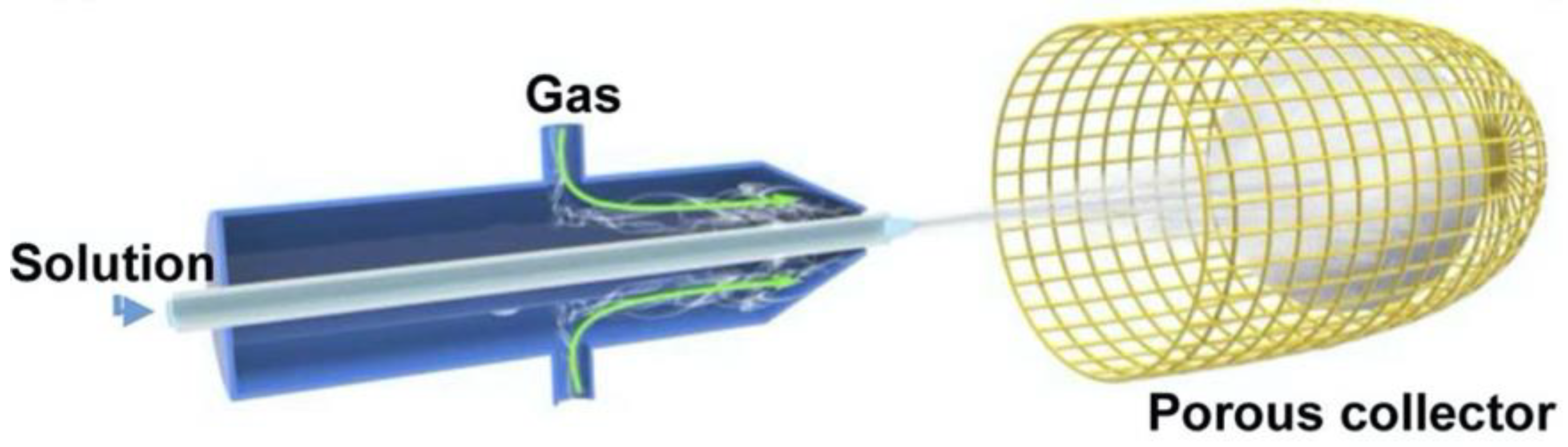
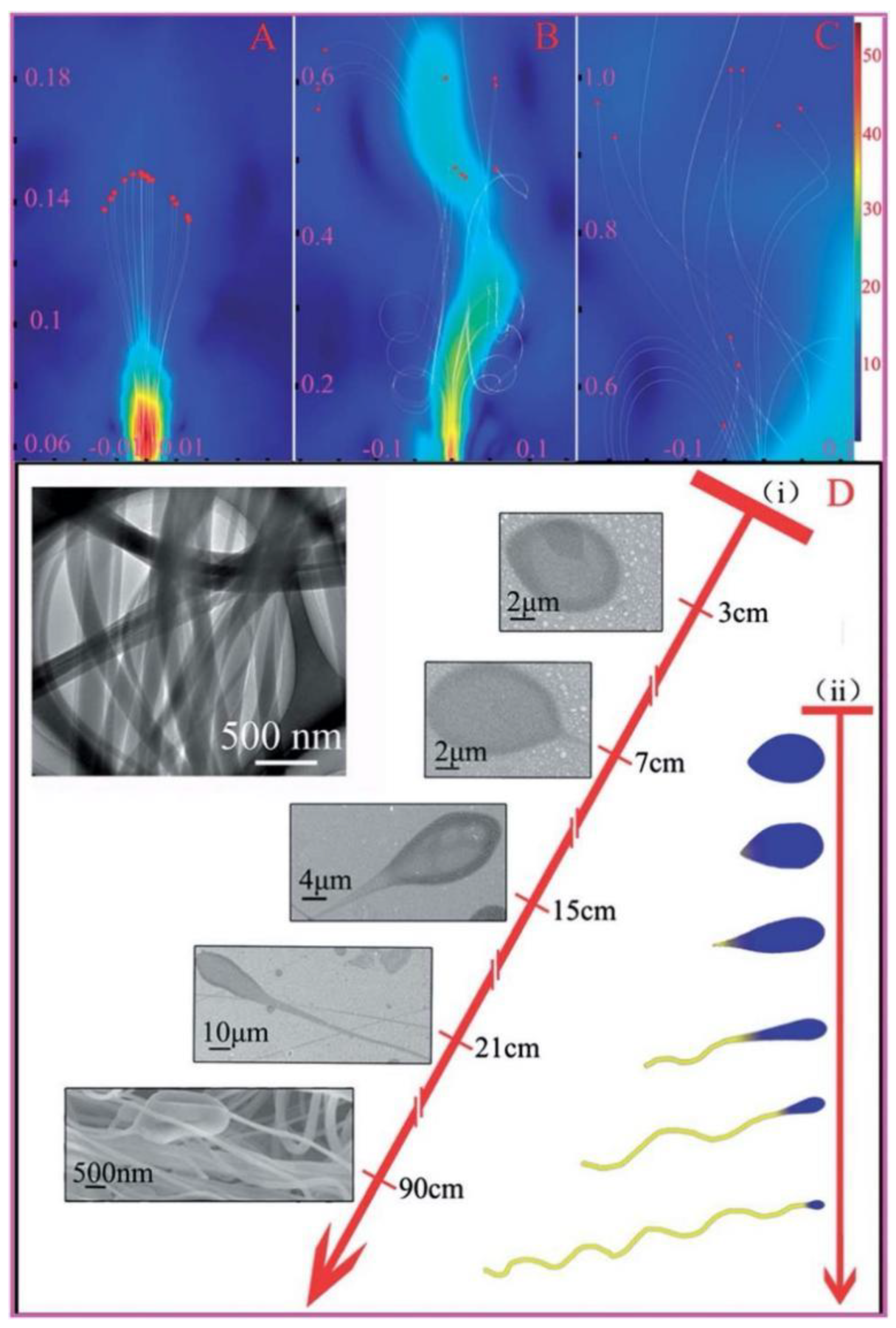
2.1.3. Solution Blow Spinning
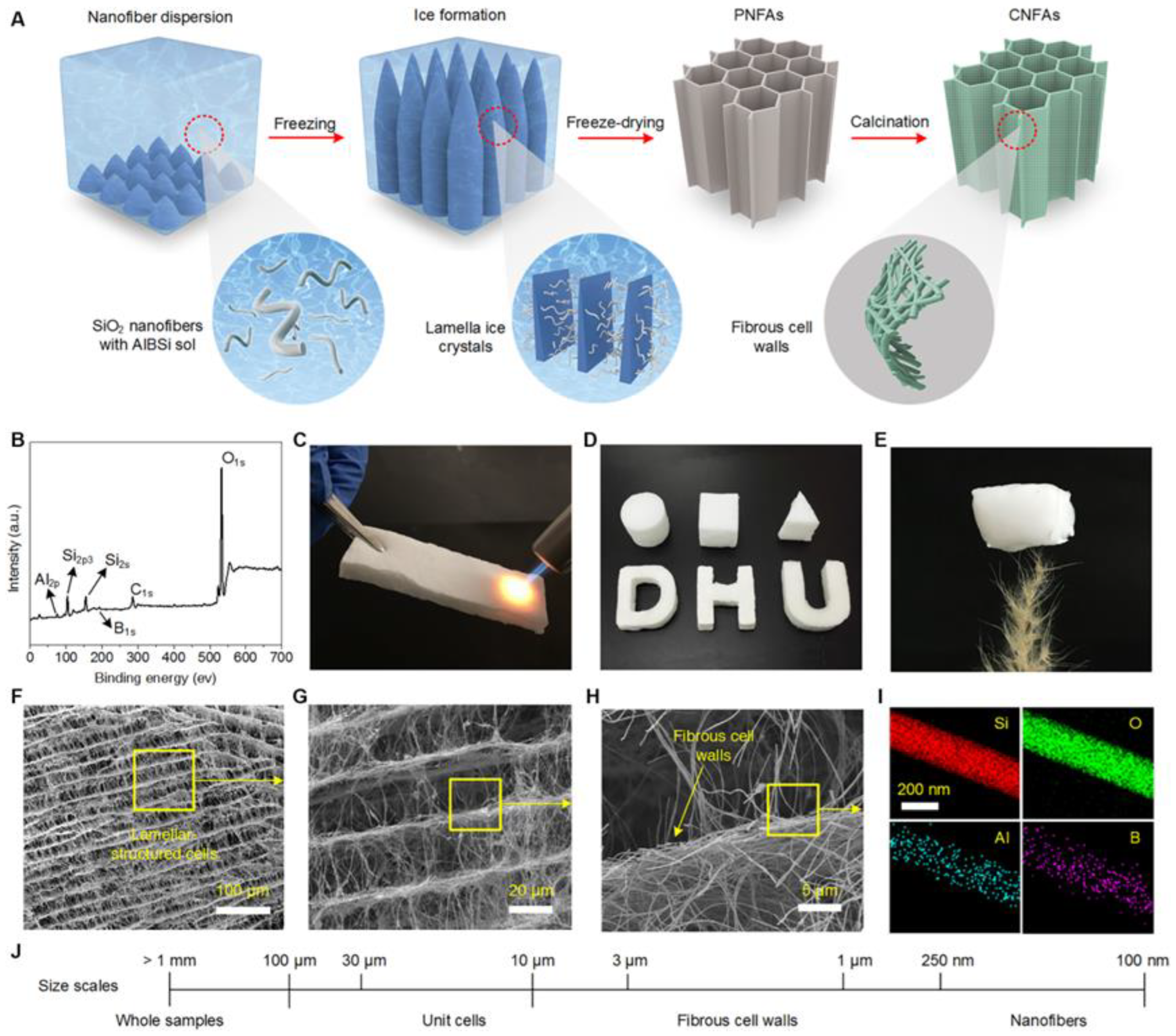
2.1.4. Self-Assembly (Freeze-Drying)
2.1.5. Other Routes
2.2. Nanofibers
2.2.1. Oxide Nanofibers
- (1)
- SiO2 nanofibers
- (2)
- Al2O3 nanofibers
- (3)
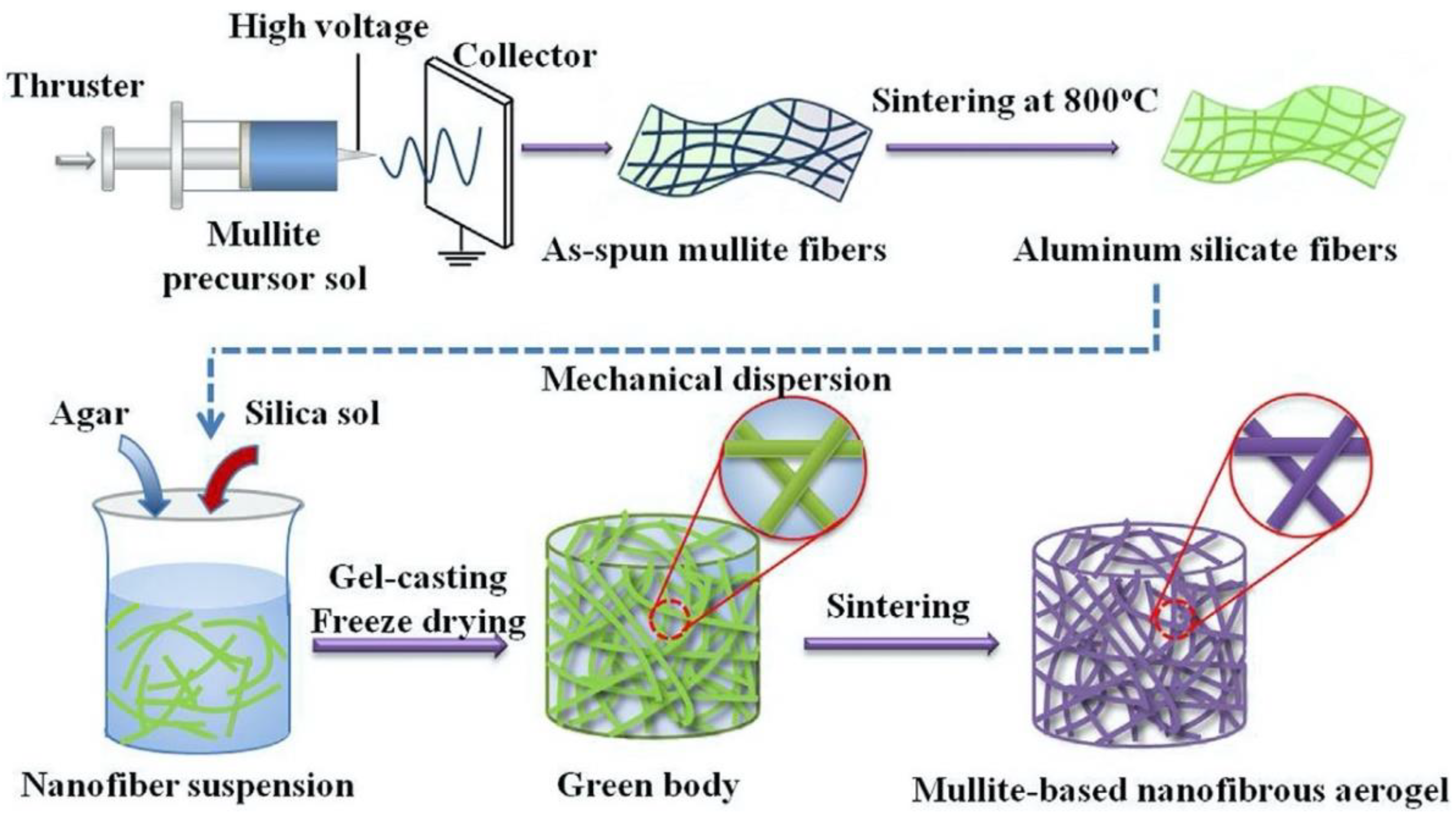
- Mullite nanofibers
- (4)
- ZrO2 nanofibers
- (5)
- Other oxide nanofibers
2.2.2. Carbide Nanofiber
2.2.3. Nitride Nanofiber
- (1)
- BN nanofiber
- (2)
- Si3N4 nanofiber
- (3)
- Other nitride nanofibers
3. Materials Prepared by the Nanofibers and Their Thermal Management Applications
4. Conclusions
- (1)
- Avoid the utilization of polymers to enhance the quality of nanofibers. Polymers result in fiber diameter reduction, formation of porous surface, and decrease in mechanical capacity. The way to eliminate this phenomenon is to enhance the solid content as much as possible and avoid polymer utilization.
- (2)
- Multiphase component nanofibers. For some single-component, ceramic-based nanofibers, their performance will decrease because of the nanometer effect. It is therefore necessary to obtain multiphase component nanofibers by adding some other components to improve their performance, such as the YSZ-Al2O3 nanofibers.
- (3)
- Improvement for efficient commercialization. The solution blow spinning possesses the highest efficiency to prepare nanofiber-based products, such as films and sponges, which ought to receive more research attention.
Author Contributions
Funding
Institutional Review Board Statement
Informed Consent Statement
Conflicts of Interest
References
- Jia, C.; Xu, Z.; Luo, D.; Xiang, H.; Zhu, M. Flexible Ceramic Fibers: Recent Development in Preparation and Application. Adv. Fiber Mater. 2022, 4, 573–603. [Google Scholar] [CrossRef] [PubMed]
- Jia, C.; Liu, Y.; Li, L.; Song, J.; Wang, H.; Liu, Z.; Li, Z.; Li, B.; Fang, M.; Wu, H. A foldable all-ceramic air filter paper with high efficiency and high-temperature resistance. Nano lett. 2020, 20, 4993–5000. [Google Scholar] [CrossRef] [PubMed]
- Jia, C.; Li, L.; Liu, Y.; Fang, B.; Ding, H.; Song, J.; Liu, Y.; Xiang, K.; Lin, S.; Li, Z.; et al. Highly compressible and anisotropic lamellar ceramic sponges with superior thermal insulation and acoustic absorption performances. Nat. Commun. 2020, 11, 3732. [Google Scholar] [CrossRef] [PubMed]
- Si, Y.; Yu, J.; Tang, X.; Tang, X.; Ge, J.; Ding, B. Ultralight nanofibre-assembled cellular aerogels with superelasticity and multifunctionality. Nat. Commun. 2014, 5, 5802. [Google Scholar] [CrossRef] [Green Version]
- Si, Y.; Wang, X.; Dou, L.; Yu, J.; Ding, B. Ultralight and fire-resistant ceramic nanofibrous aerogels with temperature-invariant superelasticity. Sci. Adv. 2018, 4, eaas8925. [Google Scholar] [CrossRef] [Green Version]
- Wang, H.; Zhang, X.; Wang, N.; Li, Y.; Feng, X.; Huag, Y.; Zhao, C.; Liu, Z.; Fang, M.; Ou, G.; et al. Ultralight, scalable, and high-temperature–resilient ceramic nanofiber sponges. Sci. Adv. 2017, 3, e1603170. [Google Scholar] [CrossRef] [Green Version]
- Li, Z.; Cui, Z.; Zhao, L.; Hussain, N.; Zhao, Y.; Yang, C.; Jiang, X.; Li, L.; Song, J.; Zhag, B.; et al. High-throughput production of kilogram-scale nanofibers by Kármán vortex solution blow spinning. Sci. Adv. 2022, 8, eabn3690. [Google Scholar] [CrossRef]
- George, G.; Luo, Z. A Review on Electrospun Luminescent Nanofibers: Photoluminescence Characteristics and Potential Applications. Curr. Nanosci. 2020, 16, 321–362. [Google Scholar] [CrossRef]
- Xue, J.; Wu, T.; Dai, Y.; Xia, Y. Electrospinning and Electrospun Nanofibers: Methods, Materials, and Applications. Chem. Rev. 2019, 119, 5298–5415. [Google Scholar] [CrossRef]
- Shamshirgar, A.S.; Rojas Hernández, R.E.; Tewari, G.C.; Fernández, J.F.; Ivanov, R.; Karppinen, M.; Hussainova, I. Functionally Graded Tunable Microwave Absorber with Graphene-Augmented Alumina Nanofibers. ACS Appl. Mater. Interfaces 2021, 13, 21613–21625. [Google Scholar] [CrossRef]
- Su, L.; Wang, H.; Niu, M.; Fan, X.; Ma, M.; Shi, Z.; Guo, S.-W. Ultralight, Recoverable, and High-Temperature-Resistant SiC Nanowire Aerogel. ACS Nano 2018, 12, 3103–3111. [Google Scholar] [CrossRef] [PubMed]
- Xue, Y.; Dai, P.; Zhou, M.; Wang, X.; Pakdel, A.; Zhang, C.; Weng, Q.; Takei, T.; Fu, X.; Popov, Z.; et al. Multifunctional superelastic foam-like boron nitride nanotubular cellular-network architectures. ACS Nano 2017, 11, 558–568. [Google Scholar] [CrossRef] [PubMed] [Green Version]
- Mahapatra, A.; Mishra, B.; Hota, G. Synthesis of ultra-fine α-Al2O3 fibers via electrospinning method. Ceram. Int. 2011, 37, 2329–2333. [Google Scholar] [CrossRef]
- Hou, T.; Li, X.; Lu, Y.; Yang, B. Highly porous fibers prepared by centrifugal spinning. Mater. Des. 2017, 114, 303–311. [Google Scholar] [CrossRef]
- Liu, H.-Y.; Chen, Y.; Liu, G.-S.; Pei, S.-G.; Liu, J.-Q.; Ji, H.; Wang, R.-D. Preparation of High-Quality Zirconia Fibers by Super-High Rotational Centrifugal Spinning of Inorganic Sol. Mater. Manuf. Process. 2013, 28, 133–138. [Google Scholar] [CrossRef]
- Tepekiran, B.N.; Calisir, M.D.; Polat, Y.; Akgul, Y.; Kilic, A. Centrifugally spun silica (SiO2) nanofibers for high-temperature air filtration. Aerosol Sci. Technol. 2019, 53, 921–932. [Google Scholar] [CrossRef]
- Sedaghat, A.; Taheri-Nassaj, E.; Naghizadeh, R. An alumina mat with a nano microstructure prepared by centrifugal spinning method. J. Non Cryst. Solids 2006, 352, 2818–2828. [Google Scholar] [CrossRef]
- Lu, Y.; Li, Y.; Zhang, S.; Xu, G.; Fu, K.; Lee, H.; Zhang, X. Parameter study and characterization for polyacrylonitrile nanofibers fabricated via centrifugal spinning process. Eur. Polym. J. 2013, 49, 3834–3845. [Google Scholar] [CrossRef]
- Wu, H.; Pan, W.; Lin, D.; Li, H. Electrospinning of ceramic nanofibers: Fabrication, assembly and applications. J. Adv. Ceram. 2012, 1, 2–23. [Google Scholar] [CrossRef] [Green Version]
- Xue, J.; Xie, J.; Liu, W.; Xia, Y. Electrospun Nanofibers: New Concepts, Materials, and Applications. Accounts Chem. Res. 2017, 50, 1976–1987. [Google Scholar] [CrossRef]
- Yan, J.; Zhao, Y.; Wang, X.; Xia, S.; Zhang, Y.; Han, Y.; Yu, J.; Ding, B. Polymer template synthesis of soft, light, and robust oxide ceramic films. Iscience 2019, 15, 185–195. [Google Scholar] [CrossRef] [PubMed] [Green Version]
- Song, X.; Liu, W.; Wang, J.; Xu, S.; Liu, B.; Cai, Q.; Ma, Y. Highly aligned continuous mullite nanofibers: Conjugate electrospinning fabrication, microstructure and mechanical properties. Mater. Lett. 2018, 212, 20–24. [Google Scholar] [CrossRef]
- Jia, C.; Li, L.; Song, J.; Li, Z.; Wu, H. Mass Production of Ultrafine Fibers by a Versatile Solution Blow Spinning Method. Accounts Mater. Res. 2021, 2, 432–446. [Google Scholar] [CrossRef]
- Daristotle, J.L.; Behrens, A.M.; Sandler, A.D.; Kofinas, P. A review of the fundamental principles and applications of solution blow spinning. ACS Appl. Mater. Interfaces 2016, 8, 34951–34963. [Google Scholar] [CrossRef] [Green Version]
- Wang, H.; Liao, S.; Bai, X.; Liu, Z.; Fang, M.; Liu, T.; Wang, N.; Wu, H. Highly flexible indium tin oxide nanofiber transparent electrodes by blow spinning. ACS Appl. Mater. Interfaces 2016, 8, 32661–32666. [Google Scholar] [CrossRef]
- Rotta, M.; Zadorosny, L.; Carvalho, C.; Malmonge, J.; Malmonge, L. YBCO ceramic nanofibers obtained by the new technique of solution blow spinning. Ceram. Int. 2016, 42, 16230–16234. [Google Scholar] [CrossRef] [Green Version]
- Silva, V.D.; Ferreira, L.S.; Simões, T.A.; Medeiros, E.S.; Macedo, D.A. 1D hollow MFe2O4 (M=Cu, Co, Ni) fibers by Solution Blow Spinning for oxygen evolution reaction. J. Colloid Interface Sci. 2019, 540, 59–65. [Google Scholar] [CrossRef]
- Li, L.; Xu, C.; Chang, R.; Yang, C.; Jia, C.; Wang, L.; Song, J.; Li, Z.; Zhang, F.; Fang, B.; et al. Thermal-responsive, super-strong, ultrathin firewalls for quenching thermal runaway in high-energy battery modules. Energy Storage Mater. 2021, 40, 329–336. [Google Scholar] [CrossRef]
- Lu, B.; He, Y.; Duan, H.; Zhang, Y.; Li, X.; Zhu, C.; Xie, E. A new ultrahigh-speed method for the preparation of nanofibers containing living cells: A bridge towards industrial bioengineering applications. Nanoscale 2012, 4, 1003–1009. [Google Scholar] [CrossRef]
- Li, G.; Zhu, M.; Gong, W.; du, R.; Eychmüller, A.; Li, T.; Lv, W.; Zhang, X. Boron Nitride Aerogels with Super-Flexibility Ranging from Liquid Nitrogen Temperature to 1000 °C. Adv. Funct. Mater. 2019, 29, 1900188. [Google Scholar] [CrossRef]
- Ichikawa, H. Polymer-derived ceramic fibers. Annu. Rev. Mater. Sci. 2016, 46, 335–356. [Google Scholar] [CrossRef]
- Wang, F.; Dou, L.; Dai, J.; Li, Y.; Huang, L.; Si, Y.; Yu, J.; Ding, B. In situ Synthesis of Biomimetic Silica Nanofibrous Aerogels with Temperature-Invariant Superelasticity over One Million Compressions. Angew. Chem. 2020, 132, 8362–8369. [Google Scholar] [CrossRef]
- Wang, X.; Dou, L.; Li, Z.; Yang, L.; Yu, J.; Ding, B. Flexible hierarchical ZrO2 nanoparticle-embedded SiO2 nanofibrous membrane as a versatile tool for efficient removal of phosphate. ACS Appl. Mater. Interfaces 2016, 8, 34668–34676. [Google Scholar] [CrossRef]
- Mi, H.-Y.; Jing, X.; Huang, H.-X.; Turng, L.-S. Instantaneous self-assembly of three-dimensional silica fibers in electrospinning: Insights into fiber deposition behavior. Mater. Lett. 2017, 204, 45–48. [Google Scholar] [CrossRef]
- Mao, X.; Si, Y.; Chen, Y.; Yang, L.; Zhao, F.; Ding, B.; Yu, J. Silica nanofibrous membranes with robust flexibility and thermal stability for high-efficiency fine particulate filtration. RSC adv. 2012, 2, 12216–12223. [Google Scholar] [CrossRef]
- Huang, T.; Zhu, Y.; Zhu, J.; Yu, H.; Zhang, Q.; Zhu, M. Self-reinforcement of light, temperature-resistant silica nanofibrous aerogels with tunable mechanical properties. Adv. Fiber Mater. 2020, 2, 338–347. [Google Scholar] [CrossRef]
- Ren, L.; Simmons, T.J.; Lu, F.; Rahmi, O.; Kotha, S.P. Template free and large-scale fabrication of silica nanotubes with centrifugal jet spinning. Chem. Eng. J. 2014, 254, 39–45. [Google Scholar] [CrossRef]
- Ren, L.; Ozisik, R.; Kotha, S.P. Rapid and efficient fabrication of multilevel structured silica micro-/nanofibers by centrifugal jet spinning. J. Colloid Interface Sci. 2014, 425, 136–142. [Google Scholar] [CrossRef]
- Wang, Y.; Li, W.; Jiao, X.; Chen, D. Electrospinning preparation and adsorption properties of mesoporous alumina fibers. J. Mater. Chem. A 2013, 1, 10720–10726. [Google Scholar] [CrossRef]
- Wang, Y.; Li, W.; Xia, Y.; Jiao, X.; Chen, D. Electrospun flexible self-standing γ-alumina fibrous membranes and their potential as high-efficiency fine particulate filtration media. J. Mater. Chem. A 2014, 2, 15124–15131. [Google Scholar] [CrossRef]
- Song, X.; Zhang, K.; Song, Y.; Duan, Z.; Liu, Q.; Liu, Y. Morphology, microstructure and mechanical properties of electrospun alumina nanofibers prepared using different polymer templates: A comparative study. J. Alloys Compd. 2020, 829, 154502. [Google Scholar] [CrossRef]
- Li, L.; Kang, W.; Zhao, Y.; Li, Y.; Shi, J.; Cheng, B. Preparation of flexible ultra-fine Al2O3 fiber mats via the solution blowing method. Ceram. Int. 2015, 41, 409–415. [Google Scholar] [CrossRef]
- Akia, M.; Capitanachi, D.; Martinez, M.; Hernandez, C.; de Santiago, H.; Mao, Y.; Lozano, K. Development and optimization of alumina fine fibers utilizing a centrifugal spinning process. Microporous Mesoporous Mater. 2018, 262, 175–181. [Google Scholar] [CrossRef]
- Liu, R.; Dong, X.; Xie, S.; Jia, T.; Xue, Y.; Liu, J.; Jing, W.; Guo, A. Ultralight, thermal insulating, and high-temperature-resistant mullite-based nanofibrous aerogels. Chem. Eng. J. 2019, 360, 464–472. [Google Scholar] [CrossRef]
- Zadeh, M.M.A.; Keyanpour-Rad, M.; Ebadzadeh, T. Synthesis of mullite nanofibres by electrospinning of solutions containing different proportions of polyvinyl butyral. Ceram. Int. 2013, 39, 9079–9084. [Google Scholar] [CrossRef]
- Song, X.; Ma, Y.; Wang, J.; Liu, B.; Yao, S.; Cai, Q.; Liu, W. Homogeneous and flexible mullite nanofibers fabricated by electrospinning through diphasic mullite sol–gel route. J. Mater. Sci. 2018, 53, 14871–14883. [Google Scholar] [CrossRef]
- Xian, L.; Zhang, Y.; Wu, Y.; Zhang, X.; Dong, X.; Liu, J.; Guo, A. Microstructural evolution of mullite nanofibrous aerogels with different ice crystal growth inhibitors. Ceram. Int. 2020, 46, 1869–1875. [Google Scholar] [CrossRef]
- Farias, R.M.D.C.; Menezes, R.R.; Oliveira, J.E.; de Medeiros, E.S. Production of submicrometric fibers of mullite by solution blow spinning (SBS). Mater. Lett. 2015, 149, 47–49. [Google Scholar] [CrossRef]
- Ruiz-Rosas, R.; Bedia, J.; Rosas, J.; Lallave, M.; Loscertales, I.; Rodríguez-Mirasol, J.; Cordero, T. Methanol decomposition on electrospun zirconia nanofibers. Catal. Today 2012, 187, 77–87. [Google Scholar] [CrossRef]
- Chen, Y.; Mao, X.; Shan, H.; Yang, J.; Wang, H.; Chen, S.; Tian, F.; Yu, J.; Ding, B. Free-standing zirconia nanofibrous membranes with robust flexibility for corrosive liquid filtration. RSC Adv. 2014, 4, 2756–2763. [Google Scholar] [CrossRef]
- Wang, H.; Lin, S.; Yang, S.; Yang, X.; Song, J.; Wang, D.; Wang, H.; Liu, Z.; Li, B.; Fang, M.; et al. High-temperature particulate matter filtration with resilient yttria-stabilized ZrO2 nanofiber sponge. Small 2018, 14, 1800258. [Google Scholar] [CrossRef] [PubMed]
- Costa, D.L.; Leite, R.S.; Neves, G.A.; Santana, L.N.D.L.; Medeiros, E.S.; Menezes, R.R. Synthesis of TiO2 and ZnO nano and submicrometric fibers by solution blow spinning. Mater. Lett. 2016, 183, 109–113. [Google Scholar] [CrossRef]
- Wang, F.; Song, L.; Zhang, H.; Meng, Y.; Luo, L.; Xi, Y.; Liu, L.; Han, N.; Yang, Z.; Tang, J.; et al. ZnO Nanofiber Thin-Film Transistors with Low-Operating Voltages. Adv. Electron. Mater. 2017, 4, 1700336. [Google Scholar] [CrossRef] [Green Version]
- Ning, Y.; Zhang, Z.; Teng, F.; Fang, X. Novel Transparent and Self-Powered UV Photodetector Based on Crossed ZnO Nanofiber Array Homojunction. Small 2018, 14, e1703754. [Google Scholar] [CrossRef]
- Ahmad, M.; Pan, C.; Luo, Z.; Zhu, J. A single ZnO nanofiber-based highly sensitive amperometric glucose biosensor. J. Phys. Chem. C 2010, 114, 9308–9313. [Google Scholar] [CrossRef]
- Wang, X.; Zhao, M.; Liu, F.; Jia, J.; Li, X.; Cao, L. C2H2 gas sensor based on Ni-doped ZnO electrospun nanofibers. Ceram. Int. 2013, 39, 2883–2887. [Google Scholar] [CrossRef]
- Zhang, M.; Wang, Y.; Zhang, Y.; Song, J.; Si, Y.; Yan, J.; Ma, C.; Liu, Y.T.; Yu, J.; Ding, B. Conductive and elastic TiO2 nanofibrous aerogels: A new concept toward self-supported electrocatalysts with superior activity and durability. Angew. Chem. 2020, 59, 23252–23260. [Google Scholar] [CrossRef]
- Zhang, R.; Wang, X.; Song, J.; Si, Y.; Zhuang, X.; Yu, J.; Ding, B. In situ synthesis of flexible hierarchical TiO2 nanofibrous membranes with enhanced photocatalytic activity. J. Mater. Chem. A 2015, 3, 22136–22144. [Google Scholar] [CrossRef]
- Wu, M.-C.; Sápi, A.; Avila, A.; Szabó, M.; Hiltunen, J.; Huuhtanen, M.; Toth, G.; Kukovecz, A.; Konya, Z.; Keiski, R.; et al. Enhanced photocatalytic activity of TiO2 nanofibers and their flexible composite films: Decomposition of organic dyes and efficient H2 generation from ethanol-water mixtures. Nano Res. 2011, 4, 360–369. [Google Scholar] [CrossRef]
- Santos, A.; Mota, M.; Leite, R.; Neves, G.A.; Medeiros, E.; Menezes, R. Solution blow spun titania nanofibers from solutions of high inorganic/organic precursor ratio. Ceram. Int. 2018, 44, 1681–1689. [Google Scholar] [CrossRef]
- Gonzalez-Abrego, M.; Hernandez-Granados, A.; Guerrero-Bermea, C.; de la Cruz, A.M.; Garcia-Gutierrez, D.; Sepulveda-Guzman, S.; Cruz-Silva, R. Mesoporous titania nanofibers by solution blow spinning. J. Sol-Gel Sci. Technol. 2017, 81, 468–474. [Google Scholar] [CrossRef]
- Qian, L.; Willneff, E.; Zhang, H. A novel route to polymeric sub-micron fibers and their use as templates for inorganic structures. Chem. Commun. 2009, 3946–3948. [Google Scholar] [CrossRef] [PubMed]
- Korhonen, J.T.; Hiekkataipale, P.; Malm, J.; Karppinen, M.; Ikkala, O.; Ras, R.H.A. Inorganic Hollow Nanotube Aerogels by Atomic Layer Deposition onto Native Nanocellulose Templates. ACS Nano 2011, 5, 1967–1974. [Google Scholar] [CrossRef] [PubMed]
- Liu, H.; Chen, Y.; Pei, S.; Liu, G.; Liu, J. Preparation of nanocrystalline titanium dioxide fibers using sol–gel method and centrifugal spinning. J. Sol-Gel Sci. Technol. 2013, 65, 443–451. [Google Scholar] [CrossRef]
- Bao, N.; Wei, Z.; Ma, Z.; Liu, F.; Yin, G. Si-doped mesoporous TiO2 continuous fibers: Preparation by centrifugal spinning and photocatalytic properties. J. Hazard. Mater. 2010, 174, 129–136. [Google Scholar] [CrossRef]
- Dai, Y.; Tian, J.; Fu, W. Shape manipulation of porous CeO2 nanofibers: Facile fabrication, growth mechanism and catalytic elimination of soot particulates. J. Mater. Sci. 2019, 54, 10141–10152. [Google Scholar] [CrossRef]
- Wu, H.; Lin, D.; Pan, W. Fabrication, assembly, and electrical characterization of CuO nanofibers. Appl. Phys. Lett. 2006, 89, 133125. [Google Scholar] [CrossRef]
- An, Z.; Ye, C.; Zhang, R.; Zhou, P. Flexible and recoverable SiC nanofiber aerogels for electromagnetic wave absorption. Ceram. Int. 2019, 45, 22793–22801. [Google Scholar] [CrossRef]
- Liu, Y.; Liu, Y.; Choi, W.C.; Chae, S.; Lee, J.; Kim, B.-S.; Park, M.; Kim, H.Y. Highly flexible, erosion resistant and nitrogen doped hollow SiC fibrous mats for high temperature thermal insulators. J. Mater. Chem. A 2017, 5, 2664–2672. [Google Scholar] [CrossRef]
- Li, Y.; Yan, G.; Zhao, Y.; Kang, W.; Li, L.; Zhuang, X.; Cheng, B.; Li, X. Emulsion-blow spun self-sustained crystalline β-silicon carbide (SiC) fiber mat and its conductivity property. Trans. Indian Ceram. Soc. 2017, 76, 159–164. [Google Scholar] [CrossRef]
- Wang, Y.; Han, C.; Zheng, D.; Lei, Y. Large-scale, flexible and high-temperature resistant ZrO2/SiC ultrafine fibers with a radial gradient composition. J. Mater. Chem. A 2014, 2, 9607–9612. [Google Scholar] [CrossRef]
- Wu, N.; Wan, L.Y.; Wang, Y.; Ko, F. Conversion of hydrophilic SiOC nanofibrous membrane to robust hydrophobic materials by introducing palladium. Appl. Surf. Sci. 2017, 425, 750–757. [Google Scholar] [CrossRef]
- Guo, A.; Roso, M.; Modesti, M.; Liu, J.; Colombo, P. Preceramic polymer-derived SiOC fibers by electrospinning. J. Appl. Polym. Sci. 2014, 131, 39836. [Google Scholar] [CrossRef]
- Dong, X.; Liu, R.; Dong, W.; Wang, Z.; Guo, A.; Liu, J.; Chen, C.; Jiang, Y. Fabrication and properties of lightweight SiOC fiber-based assembly aerogels with hierarchical pore structure. Ceram. Int. 2018, 44, 22760–22766. [Google Scholar] [CrossRef]
- Wang, P.; Cheng, L.; Zhang, L. Lightweight, flexible SiCN ceramic nanowires applied as effective microwave absorbers in high frequency. Chem. Eng. J. 2018, 338, 248–260. [Google Scholar] [CrossRef]
- Song, Y.; Li, B.; Yang, S.; Ding, G.; Zhang, C.; Xie, X. Ultralight boron nitride aerogels via template-assisted chemical vapor deposition. Sci. Rep. 2015, 5, 10337. [Google Scholar] [CrossRef] [Green Version]
- Su, L.; Li, M.; Wang, H.; Niu, M.; Lu, D.; Cai, Z. Resilient Si3N4 nanobelt aerogel as fire-resistant and electromagnetic wave-transparent thermal insulator. ACS Appl. Mater. Interfaces 2019, 11, 15795–15803. [Google Scholar] [CrossRef]
- Huo, W.; Zhang, X.; Xu, J.; Hu, Z.; Yan, S.; Gan, K.; Yang, J. In situ synthesis of three-dimensional nanofiber-knitted ceramic foams via reactive sintering silicon foams. J. Am. Ceram. Soc. 2019, 102, 2245–2250. [Google Scholar] [CrossRef]
- Zhang, X.; Huo, W.; Chen, Y.; Hu, Z.; Wang, Y.; Gan, K.; Yang, J. Novel micro-spherical Si3N4 nanowire sponges from carbon-doped silica sol foams via reverse templating method. J. Am. Ceram. Soc. 2019, 102, 962–969. [Google Scholar]
- Wu, H.; Sun, Y.; Lin, D.; Zhang, R.; Zhang, C.; Pan, W. GaN nanofibers based on electrospinning: Facile synthesis, controlled assembly, precise doping, and application as high performance UV photodetector. Adv. Mater. 2009, 21, 227–231. [Google Scholar] [CrossRef]
- Dou, L.; Zhang, X.; Cheng, X.; Ma, Z.; Wang, X.; Si, Y.; Yu, J.; Ding, B. Hierarchical cellular structured ceramic nanofibrous aerogels with temperature-invariant superelasticity for thermal insulation. ACS Appl. Mater. Interfaces 2019, 11, 29056–29064. [Google Scholar] [CrossRef] [PubMed]
- Su, L.; Wang, H.; Niu, M.; Dai, S.; Cai, Z.; Yang, B.; Huyan, H.; Pan, X. Anisotropic and hierarchical SiC@ SiO2 nanowire aerogel with exceptional stiffness and stability for thermal superinsulation. Sci. Adv. 2020, 6, eaay6689. [Google Scholar]
- Xu, X.; Fu, S.; Guo, J.; Li, H.; Huang, Y.; Duan, X. Elastic ceramic aerogels for thermal superinsulation under extreme conditions. Mater. Today 2021, 42, 162–177. [Google Scholar] [CrossRef]
- Hu, P.; Liu, L.; Zhao, M.; Wang, J.; Ma, X.; Wang, J. Design, Synthesis, and Use of High Temperature Resistant Aerogels Exceeding 800 °C. ES Mater. Manuf. 2021, 15, 14–33. [Google Scholar] [CrossRef]
- Wang, B.; Niu, Y.; Zheng, S.; Yin, Y.; Ding, M. A High Temperature Sensor Based on Sapphire Fiber Fabry-Perot Interferometer. IEEE Photon Technol. Lett. 2019, 32, 89–92. [Google Scholar] [CrossRef]
- Chen, Y.; Chen, Y.; Ding, D.; Ding, Y.; Choi, Y.; Zhang, L.; Yoo, S.; Chen, D.; Deglee, B.; Xu, H.; et al. A robust and active hybrid catalyst for facile oxygen reduction in solid oxide fuel cells. Energy Environ. Sci. 2017, 10, 964–971. [Google Scholar] [CrossRef] [Green Version]
- He, Z.; Li, C.; Chen, C.; Tong, Y.; Luo, T.; Zhan, Z. Membrane-assisted propane partial oxidation for solid oxide fuel cell applications. J. Power Sources 2018, 392, 200–205. [Google Scholar] [CrossRef]
- Gao, Z.; Mogni, L.V.; Miller, E.C.; Railsback, J.G.; Barnett, S.A. A perspective on low-temperature solid oxide fuel cells. Energy Environ. Sci. 2016, 9, 1602–1644. [Google Scholar] [CrossRef]
- Yang, R.; Hu, F.; An, L.; Armstrong, J.N.; Hu, Y.; Li, C.; Huang, Y.; Ren, S. A Hierarchical Mesoporous Insulation Ceramic. Nano Lett. 2019, 20, 1110–1116. [Google Scholar] [CrossRef]
- Cheng, H.; Xue, H.; Hong, C.; Zhang, X. Preparation, mechanical, thermal and ablative properties of lightweight needled carbon fibre felt/phenolic resin aerogel composite with a bird’s nest structure. Compos. Sci. Technol. 2017, 140, 63–72. [Google Scholar] [CrossRef]
- Jin, H.; Zhou, X.; Xu, T.; Dai, C.; Gu, Y.; Yun, S.; Hu, T.; Guan, G.; Chen, J. Ultralight and Hydrophobic Palygorskite-based Aerogels with Prominent Thermal Insulation and Flame Retardancy. ACS Appl. Mater. Interfaces 2020, 12, 11815–11824. [Google Scholar] [CrossRef] [PubMed]
- Nguyen, B.N.; Meador, M.A.B.; Scheiman, D.; McCorkle, L. Polyimide Aerogels Using Triisocyanate as Cross-linker. ACS Appl. Mater. Interfaces 2017, 9, 27313–27321. [Google Scholar] [CrossRef] [PubMed]
- Randall, J.P.; Meador, M.A.B.; Jana, S.C. Tailoring Mechanical Properties of Aerogels for Aerospace Applications. ACS Appl. Mater. Interfaces 2011, 3, 613–626. [Google Scholar] [CrossRef] [PubMed]


| Methods | Material Types | Advantages | Disadvantages | Fiber Diameter | Industrialization Prospect |
|---|---|---|---|---|---|
| Centrifugal spinning | Melt | High efficiency | Relatively poor flexibility | >1 μm | High |
| Solution | High efficiency; broad material choice | Removal of polymer | Tens of nanometers to a few microns | Relatively high | |
| Sol | High efficiency; high yield; polymer free | Ununiform diameter | Hundreds of nanometers to tens of microns | Relatively high | |
| Electrospinning | Solution | Small and uniform diameter; diverse compositions and morphologies | Low efficiency; high voltage; removal of polymer | Tens of nanometers to a few microns | Relatively low |
| Sol | High yield; polymer free | Nonuniform diameter; high voltage | Tens of nanometers to a few microns | Relatively low | |
| Solution blow spinning | Solution | Simple and safe process; high efficiency; diverse compositions and structures | Removal of polymers | Tens of nanometers to a few microns | Relatively high |
| Self-assembly | Solution | Ribbon structure | Limited material choice; low efficiency; removal of organic | Width: hundreds of nanometers to a few microns. Thickness: a few nanometers | Low |
| Polymer conversion | Solution | Non-oxide component | Low efficiency; calcination in inert atmosphere | Tens of nanometers to a few microns | Relatively low |
| Materials | Density (mg·cm−1) | Thermal Conductivity (W·m−1·K−1) |
|---|---|---|
| SiO2 nanofibrous [84] | 0.2~17 | 0.0223 |
| Al2O3, SiO2 nanofiber [44] | 34.64~48.89 | 0.03274~0.04317 |
| Al2O3, ZrO2 nanofibrous [84] | - | 0.0322 at 1300 °C |
| Al2O3-SiO2 micron fibers and nanoparticles [84] | 0.36 | 0.082 at 1200 °C |
| BN nanobelts [30] | 15.5 | 0.0346 ± 0.0015 |
| Si3N4 nanobelts [77] | 1.8~9.6 | 0.029 |
| SiC Nanowires [84] | 11 | 0.025 |
Publisher’s Note: MDPI stays neutral with regard to jurisdictional claims in published maps and institutional affiliations. |
© 2022 by the authors. Licensee MDPI, Basel, Switzerland. This article is an open access article distributed under the terms and conditions of the Creative Commons Attribution (CC BY) license (https://creativecommons.org/licenses/by/4.0/).
Share and Cite
Zhang, J.; Zhang, J.; Sun, Q.; Ye, X.; Ma, X.; Wang, J. Sol–Gel Routes toward Ceramic Nanofibers for High-Performance Thermal Management. Chemistry 2022, 4, 1475-1497. https://doi.org/10.3390/chemistry4040098
Zhang J, Zhang J, Sun Q, Ye X, Ma X, Wang J. Sol–Gel Routes toward Ceramic Nanofibers for High-Performance Thermal Management. Chemistry. 2022; 4(4):1475-1497. https://doi.org/10.3390/chemistry4040098
Chicago/Turabian StyleZhang, Jing, Junxiong Zhang, Qilong Sun, Xinli Ye, Xiaomin Ma, and Jin Wang. 2022. "Sol–Gel Routes toward Ceramic Nanofibers for High-Performance Thermal Management" Chemistry 4, no. 4: 1475-1497. https://doi.org/10.3390/chemistry4040098