1. Introduction
T2K (Tokai to Kamioka) is the first long-base accelerator experiment of the second generation in Japan [
1,
2]. This project is aimed at finding a new source of violation of charge-conjugation parity-reversal (CP) symmetry in the neutrino sector, which is a necessary element for explaining physical phenomena beyond the standard model: in particular, the baryon asymmetry of the universe, as well as improving the accuracy of measuring the parameters of atmospheric neutrino oscillations, such as the difference,
, between the masses squared,
and
, of the neutrino mass eigenstates,
and
, and the mixing angle,
.
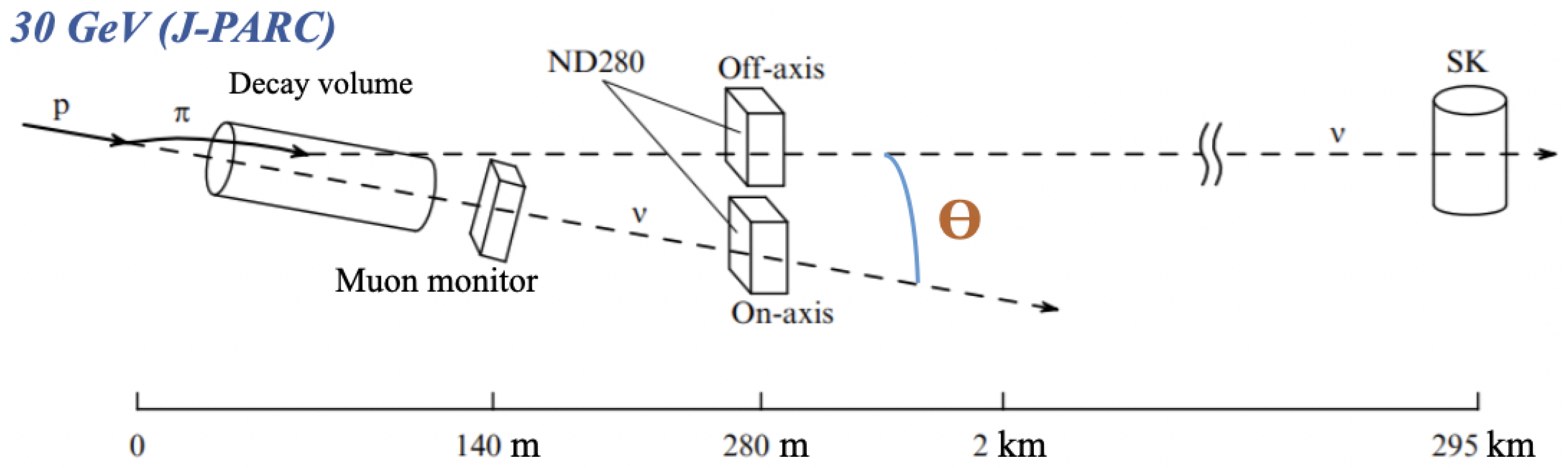
The general scheme of the T2K experiment is shown in
Figure 1. The main elements of T2K are a neutrino channel, a complex of near detectors (ND280) located at a distance of 280 m from the proton target [
3] and a far detector SuperKamiokande (SK) [
4,
5]—Cherenkov detector filled with 50 kilotons of ultra-pure water as a neutrino target, located 295 km away from the Japan Proton Accelerator Research Complex (J-PARC).
The main feature of T2K is a quasi-monoenergetic off-axis neutrino beam at an angle
of 2.5 degrees to the proton beam axis, tuned to the first oscillation maximum at a peak beam energy of 0.6 GeV [
6]. The off-axis configuration of the neutrino beam makes it possible to obtain a relatively pure muon neutrino composition with a small contamination of electron neutrinos.
A high-intensity proton beam generated by a 30 GeV proton synchrotron (PS) at the J-PARC hits a graphite target, resulting in the formation of secondary particles, namely pions and kaons. Positively charged particles, mainly , are focused by three toroidal pulsed magnets in the direction of the 94 m long neutrino channel filled with helium at a pressure of 1 atm, in order to reduce absorption and uncontrolled generation of pions. Inside the neutrino channel, pions decay in flight into muons and muon neutrinos. All the hadrons, as well as muons below 5 GeV/c, are stopped by the beam dump. Neutrinos and high-energy muons pass through the beam dump and then fall into the ND280 detectors.
The ND280 is divided in two parts: one of which is a neutrino beam monitor located on the proton beam axis [
7], and the second one is an off-axis neutrino detector complex located on the axis connecting the decay volume and the far detector SK, i.e., at an angle of 2.5 degrees to the proton beam. The ND280 complex is mainly designed to measure the parameters and control the direction and intensity of the initial neutrino beam, i.e., before the beginning of oscillations.
Currently, the T2K experiment results exclude the CP-conservation (with CP-violation phase,
or
) at the level of 90% CL (confidence level) [
8,
9]. In accordance with the need to increase the sensitivity of T2K to CP-violation, it is necessary to reduce any systematic uncertainties in predicting the number of events at the far SK detector. Thus, in 2017, the T2K Collaboration decided to launch an extensive upgrade program of the near off-axis detector, within the framework of which a highly segmented neutrino detector SuperFGD is planned to be constructed and to be put into operation [
10].
2. Upgrade Program Motivation
The current near off-axis ND280 consists of a UA1 experiment magnet, a neutral pion detector (
detector–P0D) [
11], a tracker that includes three time projection chambers (TPCs) [
12] surrounding two fine-grained scintillation detectors (FGDs) [
13], an electromagnetic calorimeter and a side muon range detector (SMRD) [
14].
The current off-axis ND280 is constrained to angular acceptance of mostly forward going events, and, in addition, the reconstruction of short tracks is limited. Thus, not every type of neutrino interaction can be analyzed with sufficient precision.
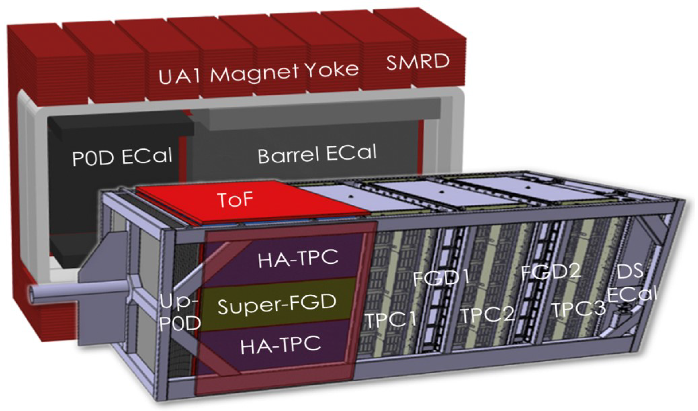
Figure 2 shows a general view of the current off-axis ND280 and the idea of its upgrade, which is the replacement of the P0D by a novel 3D (three-dimensional) fine-grained detector SuperFGD, which is planned to be located in the central part of the new tracker. At the same time, two high-angle time-projection chambers (HA-TPCs) to be installed above and below SuperFGD and six time-of-flight detectors (ToFs) [
15] around the new tracker.
The fine-grained structure of the SuperFGD is designed to provide a full solid-angle acceptance (4-acceptance) of charged particles produced from the neutrino interaction vertices; as in the far detector SK, due to the isotropic nature of the SuperFGD, significantly increases the detection efficiency of short tracks. In addition, both fine segmentation and high light output of the SuperFGD are able to reduce the energy threshold for detection of protons and pions and facilitate electron/gamma separation. In addition, the detection of neutrons becomes possible.
Thus, one expects reducing the systematic errors in T2K from the current level of 6–7% to 3–4% [
10].
3. SuperFGD
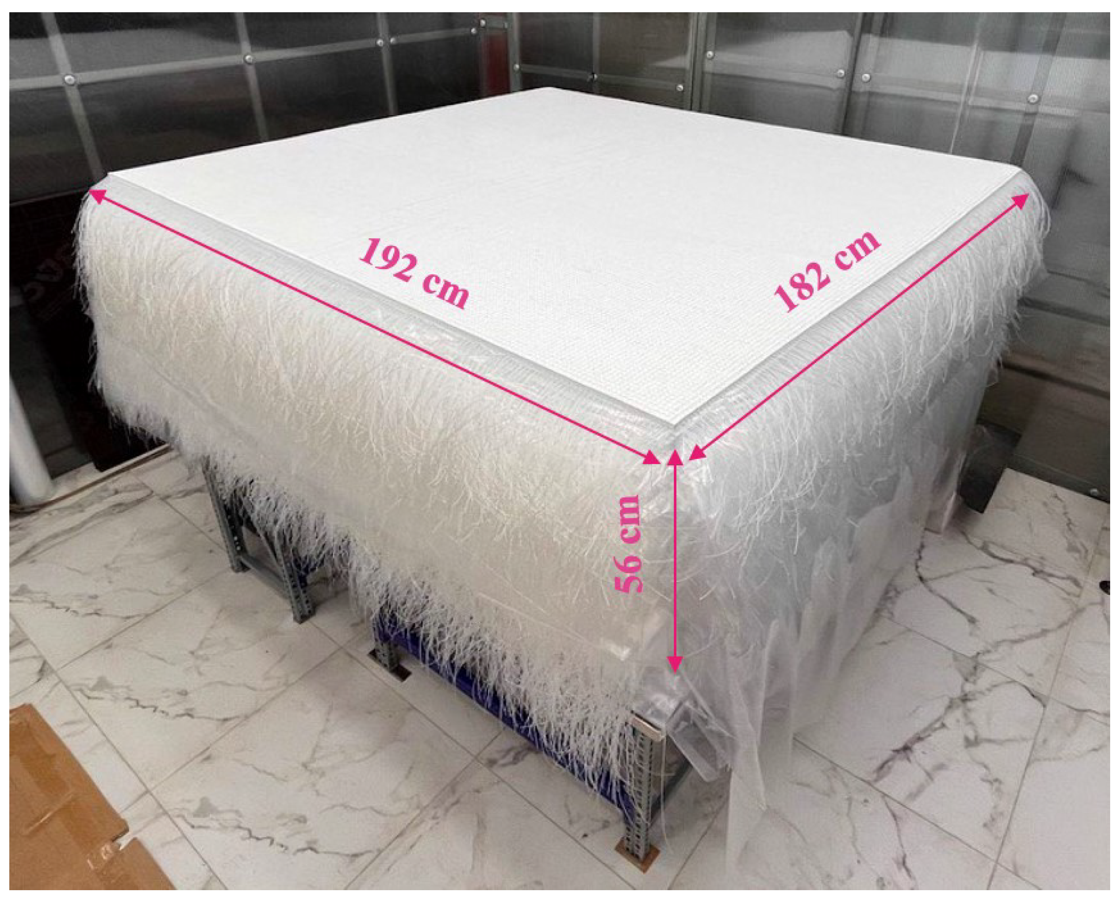
SuperFGD, as the key element of the upgraded ND280, is a fully active neutrino target consisting of about two million optically isolated plastic scintillator cubes with 1 cm sides. SuperFGD’s full size is
cm
and its total weight is about 2 tons. Each SuperFGD cube provides a 3D optical readout [
16,
17] by a diameter ⌀1 mm
Kuraray Y11 (200) multiclad S-type wavelength shifting (WLS) fibers and
Hamamatsu Photonics multi-pixel photon counters (MPPCs) of the S13360-1325PE series. The total number of SuperFGD electronic readout channels is about 60,000. The detector assembled using the fishing line method [
18] is shown in
Figure 3.
4. SuperFGD Cubes
SuperFGD cubes have been manufactured at
UNIPLAST Co. (Vladimir, Russia) by the injection molding method [
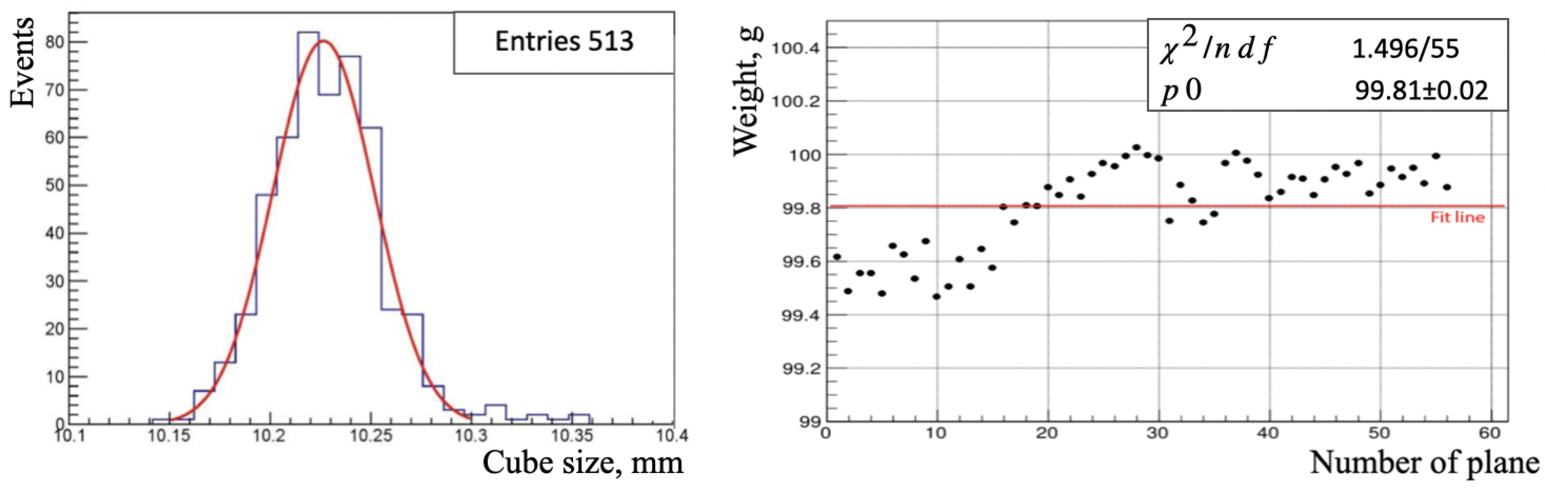
19]. The chemical composition of the cubes is based on polystyrene with scintillator dopants: 1.5% of paraterphenyl (PTP) and 0.01% of 1,4-bis(5-phenyloxazol-2-yl) benzene (POPOP). After manufacturing, each cube is covered with a reflective layer with a thickness in the range from 50 to 80 µm by etching the surface of the cubes with a chemical substance. In addition, three orthogonal through holes with a diameter of 1.5 mm for WLS fibers were drilled in each cube using precision 3D milling and engraving machines. As a result, each side of the SuperFGD cube has an average size of 10.23 mm ± 0.025 mm, and the weight of a single cube is 0.9977 ± 0.0002 g [
18]. These data are shown in
Figure 4.
The production of all 2 × 10 scintillator cubes was finished in January 2021.
5. SuperFGD Prototypes
Several SuperFGD prototypes have been tested in experimental beams with charged particles and neutrons.
The scintillator cubes for these prototypes are similar to the cubes for the SuperFGD itself, except for the manufacturing method. In the case of prototypes, cubes were made by extrusion of long slabs with a thickness of 1 cm, followed by cutting in the size of cm.
Tests with two SuperFGD prototypes: 125 (
cm
) cubes with 75 WLS fibers and 9216 (
cm
) cubes with 1728 WLS fibers were carried out in charged particle beams at CERN (the European Organization for Nuclear Research, Geneva, Switzerland) in 2017 [
20] and 2018 [
21], respectively.
As for the first prototype, the parameters of individual cubes were investigated using positively charged particles with a beam momentum of 6 GeV/
c (where
c denotes the speed of light in vacuum) with the following results: the average light yield per a fiber was about 40 p.e./MIP (photoelectrons per minimum ionizing particle) and about 80 p.e./MIP for the sum of two fibers, i.e., for a cube; the average time resolution per a fiber was 0.95 ns, and per two fibers, i.e., for a cube, was approximately 0.69 ns; and the optical crosstalk between neighboring cubes through one side of the cube was approximately 3%. These results were obtained using a 16-channel
CAEN digitizer DT5742 with a 5 GHz sampling rate and 12-bit resolution [
22].
The results of the test with the second prototype were aimed at studying the particle tracks identification within the beam momentum range from 0.4 to 8 GeV/
c. At the same time, three types of
Hamamatsu MPPCs: S13360-1325CS, S13081-050CS and S12571-025C [
23,
24] were mounted on the surface of the prototype throughout the volume to provide the required number of readout channels. Front-end electronics were based on the CITIROC (Cherenkov imaging telescope integrated read out chip) with the main component in this scheme: the front end board (FEB), on which three CITIROC chips are placed [
25]. This type of electronics is similar to the one that will be used in the SuperFGD itself.
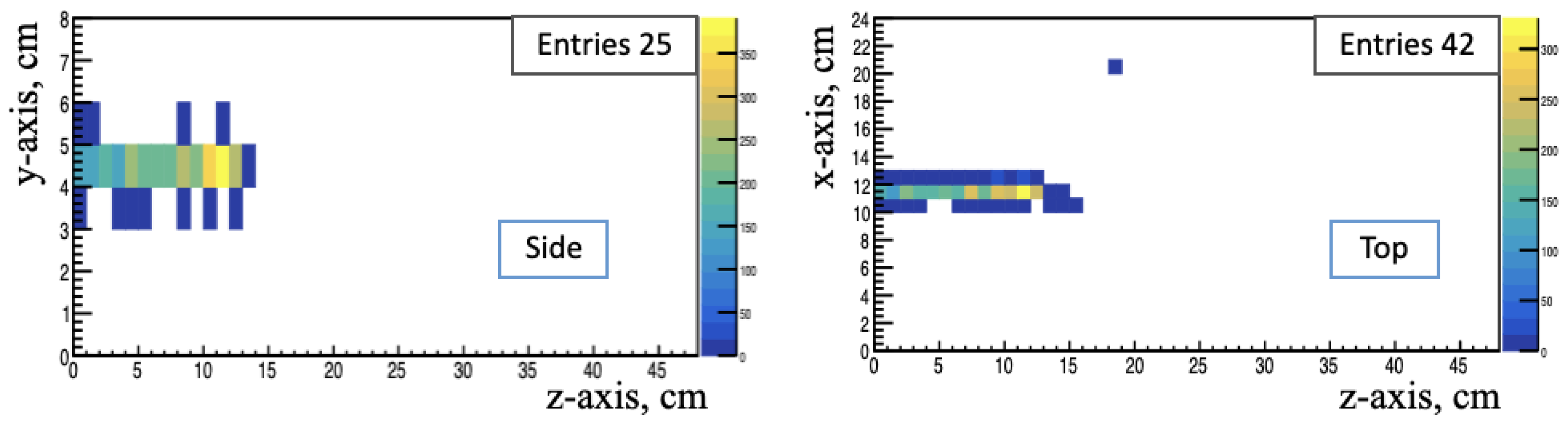
As an example, the proton track in two projections: top view (
-plane) and side view (
-plane), selected from a hadron beam with a momentum of 0.5 GeV/
c in a magnetic field of 0.2 T, close to one in the ND280 magnet, stopped inside the volume of the second SuperFGD prototype, is presented in
Figure 5.
Due to the good enough time resolution and high granularity of the SuperFGD, it becomes possible to measure the kinetic energy of neutrons in anti-neutrino interactions with the ToF method. This makes possible to improve the model of the neutrinos interaction with the nuclei of the detector substance and the methods of reconstruction of the neutrino energy.
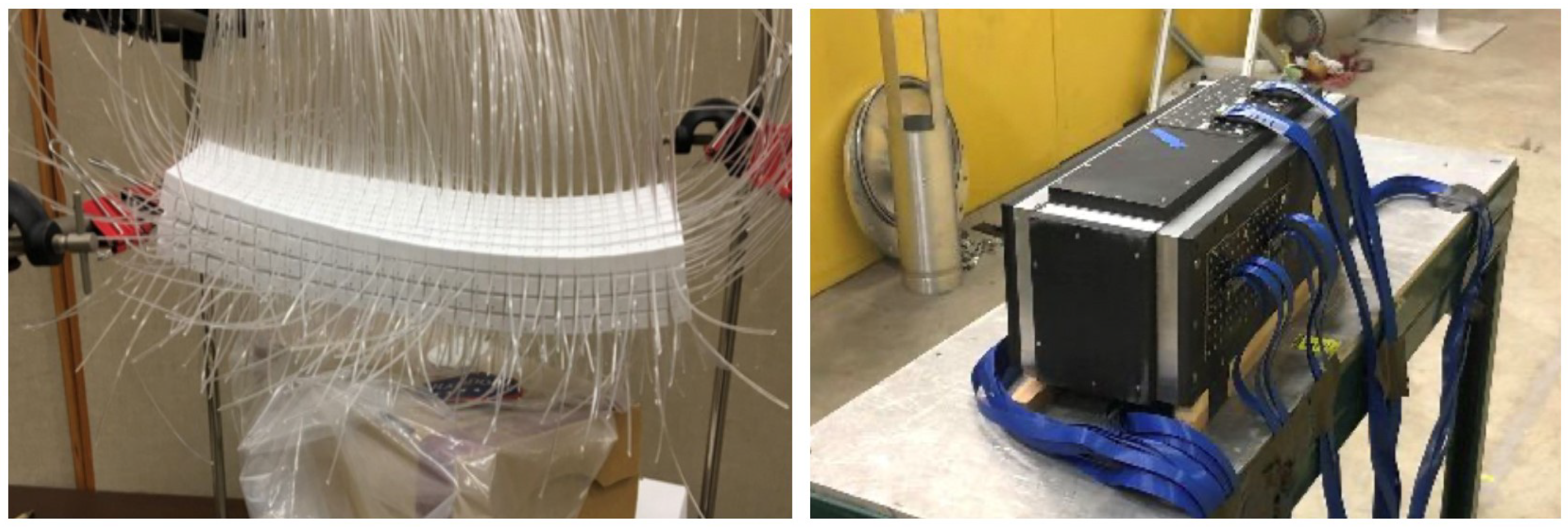
Tests with both SuperFGD prototypes: the larger SuperFGD prototype (
cm
) and US–Japan prototype with dimensions of
cm
(see
Figure 6) were carried out at the Los Alamos National Laboratory (LANL) with neutrons in the range of kinetic energy from 0 to 0.8 GeV, provided by the Weapons Neutron Research (WNR) facility in 2019 and 2020 [
26,
27].
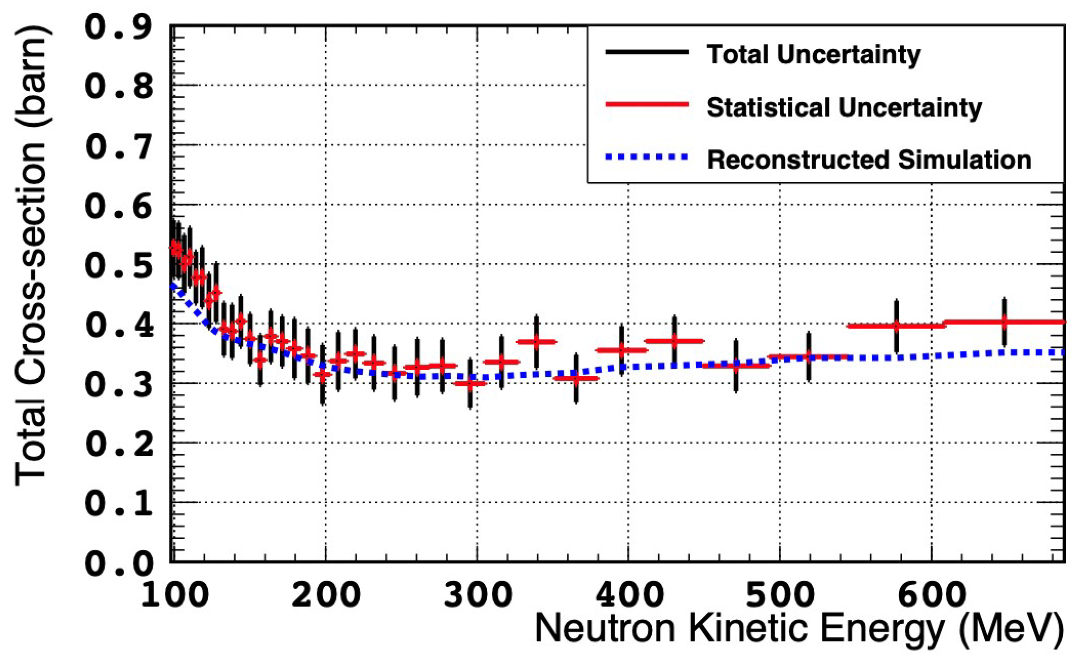
During these tests, the total neutron-scintillator cross-section is measured as a function of neutron energy to demonstrate the capability of the SuperFGD to detection of neutrons (see
Figure 7).
As can be seen from the
Figure 7, the total measured neutron cross-section in the scintillator in the range from 98 to 688 MeV is 0.36 ± 0.05 barn.
6. SuperFGD Mechanical Box
The housing for the SuperFGD cubes is a light-protected mechanical box with a sandwich structure based on the carbon-fiber (CF). It consists of six composite panels. The sandwich structure ensures the strength of the box, is designed for low density and provides extremely small deformation under the weight of the detector. The sandwich structure is the following: A
Divinycell H250 core [
28] (semi-rigid PVC (polyvinyl chloride) foam with excellent mechanical properties to low weight) with a density of 0.25 g/cm
is glued between two CF skins of 2.3 mm thickness each. The core thickness is variable between the side, top and bottom panels. Aluminum ribs built in the sandwich structure form a rigid frame at the edges of the composite panel. The datum surface outside the sandwich is made of G-10 with precision-milled cavities in order to attach MPPCs and LED (light emitting diode) calibration tools.
The ⌀3 mm holes available for the insertion of the WLS fibers are drilled through the box panels according to the whole geometry of the cubes stack, which were measured in advance [
18]. A foam layer with a thickness of about 5 mm is placed inside the box between the panel wall and the cubes to smooth the non-uniformities of cube assembly and fix its position inside the box. The whole weight of the box is about 550 kg.
7. SuperFGD Photosensors
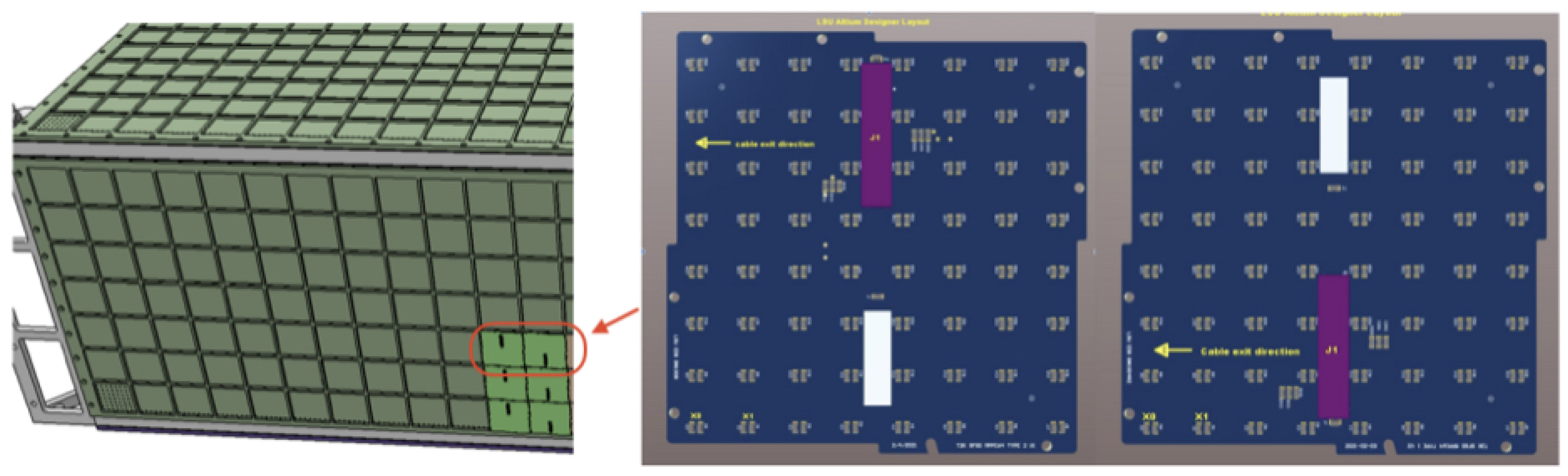
A total of 56,384 MPPCs of the S13360-1325PE series of
Hamamatsu Photonics with a sensitive area of
mm
and a pixel pitch of 25 µm each are arranged on a printed circuit boards (PCBs) with two types of connector positions in the form of
matrices (see
Figure 8). In addition, the main characteristics of these MPPCs include: total number of pixels of 2668, breakdown voltage of
V, photon detection efficiency at 500 nm (green light) of 25%, gain of
, and average dark count rate of below 40 kHz at 20 °C, according to the
Hamamatsu specification [
24]. The parameters of an individual MPPC64–PCB are the following: thickness of 1.7 mm and the length of one side is 8.83 mm. Thus, a total of 881 MPPC64–PCBs to be used to measure scintillation light collected by WLS fibers from SuperFGD cubes.
8. SuperFGD Calibration System
The LED calibration system with a light guide plate (LGP) is necessary for the initial check of all SuperFGD channels before and after the WLS fibers installation, as well as for the regular channel-by-channel gain calibration.
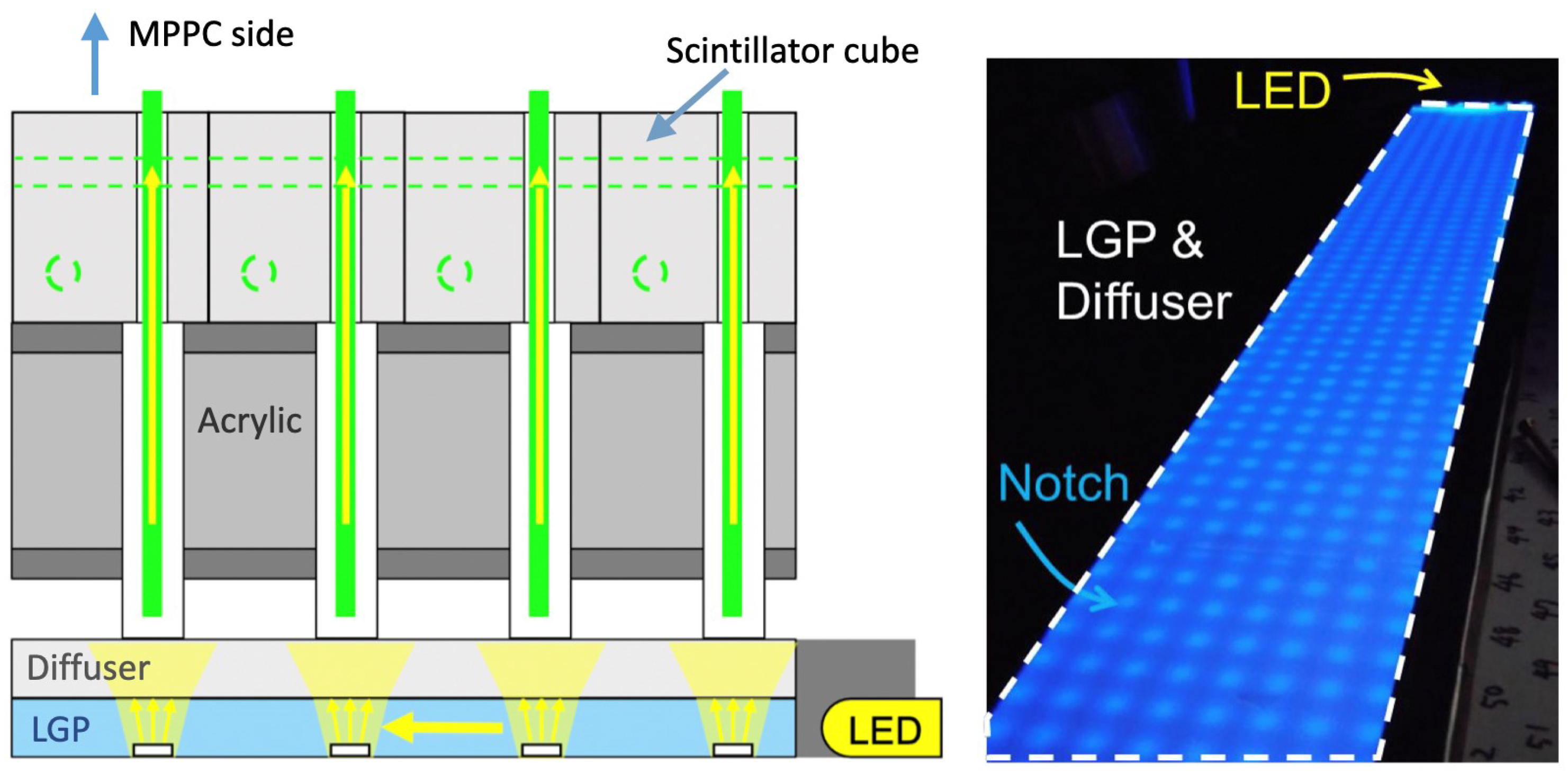
The LGP module includes the following components: a PCB with a LED-array and a LGP with a diffuser integrated into a light-tight black acrylic container with a thickness of about 8 mm (see
Figure 9). It holds the LEDs in the correct position and provides an optical divider between the LGP modules and the external SuperFGD box surface. The inside clearance between the LGP and the container is 0.5 mm and to be filled with a shim plate, and the outside clearance between the LGP modules themselves is 1.0 mm.
The principle of operation of the LGP module is as follows: light from the LED source propagating through the LGP module is reflected from its walls and, captured by one of the set of ⌀3 mm notches with a depth of 0.01 mm, is re-emitted at an angle necessary to hit the WLS fiber using a diffuser.
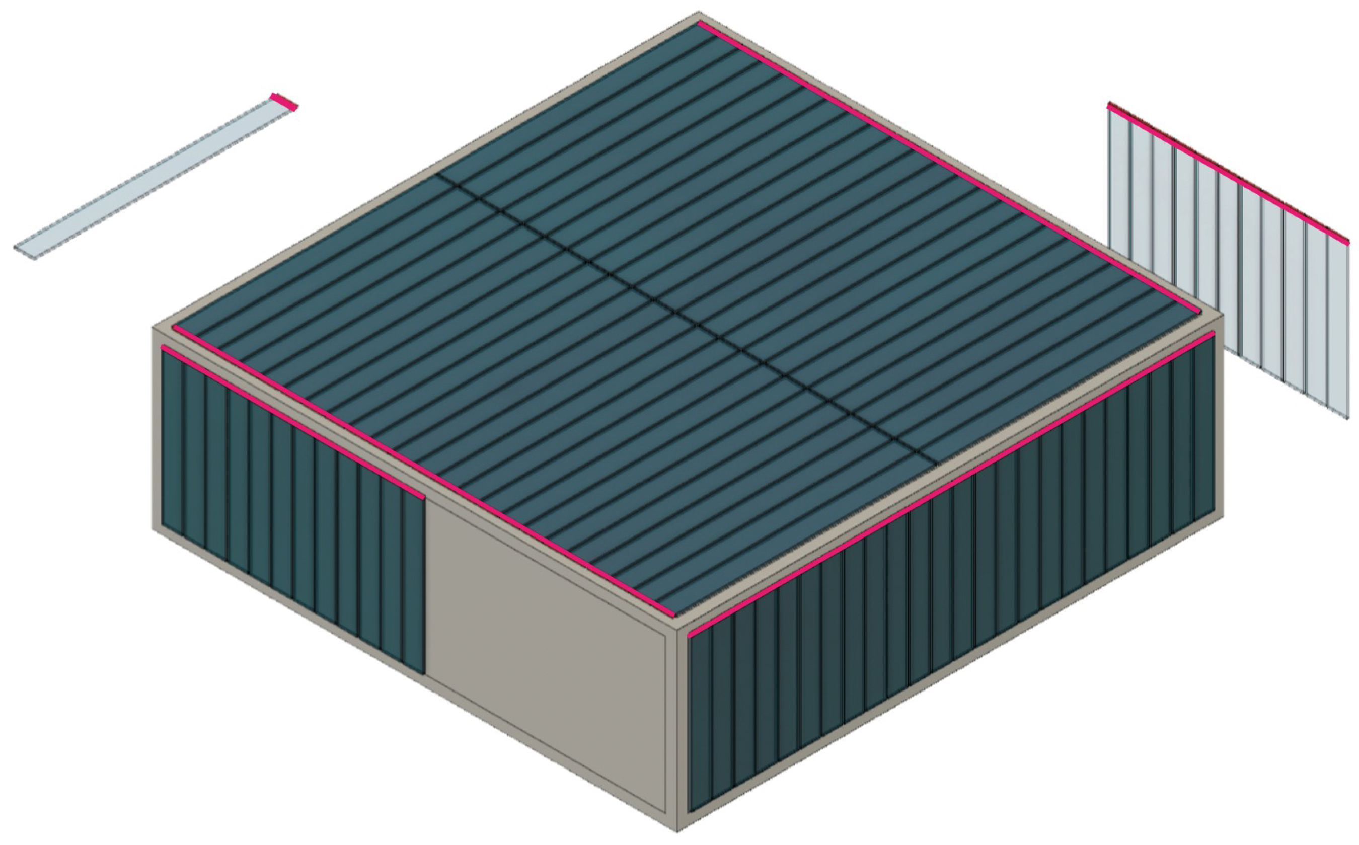
This calibration system is designed to be integrated into the SuperFGD mechanical box. Therefore, one has to avoid any interference with some objects on the surface of the box, such as MPPC64–PCBs, signal cables, and especially with the bracket at the side corner. In this regard, the LGP modules to be attached to the surface of the box with the orientation of the LED part (highlighted in red in
Figure 10) to the bottom corner.
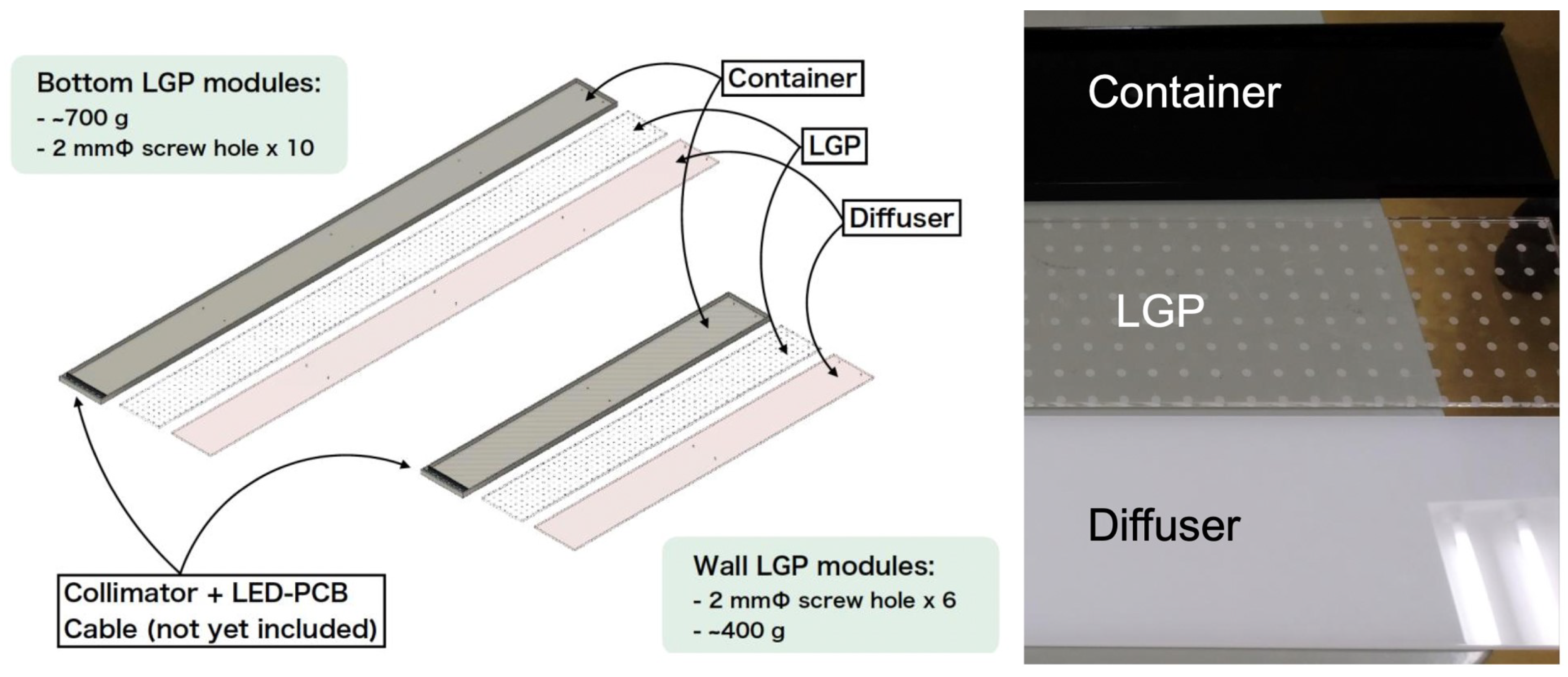
There are long and short types of LGP modules with a length of about 1 m and 0.6 m, respectively. The bottom plate and a half area of the side plate of the mechanical box are covered by long and short modules, respectively. A single long module can cover
channels with 7 LEDs, and a single short module can cover
channels with 7 LEDs, simultaneously. A total of 46 modules are necessary to cover
channels of the bottom plate of the box, and 47 modules are necessary to cover
channels of the side plate of the box (see
Figure 11).
9. SuperFGD Assembling at J-PARC
All 56 layers of the scintillator cubes assembled at Institute for Nuclear Research of the Russian Academy of Sciences (INR RAS, Moscow, Russia), as well as the assembly platform designed and manufactured at the Joint Institute for Nuclear Research (JINR, Dubna, Russia), have been delivered to J-PARC. The mechanical box for the SuperFGD was delivered there from CERN. Currently, the assembly of the SuperFGD is conducted in the Neutrino Assembly (NA) building at J-PARC.
9.1. SuperFGD Assembling Platform
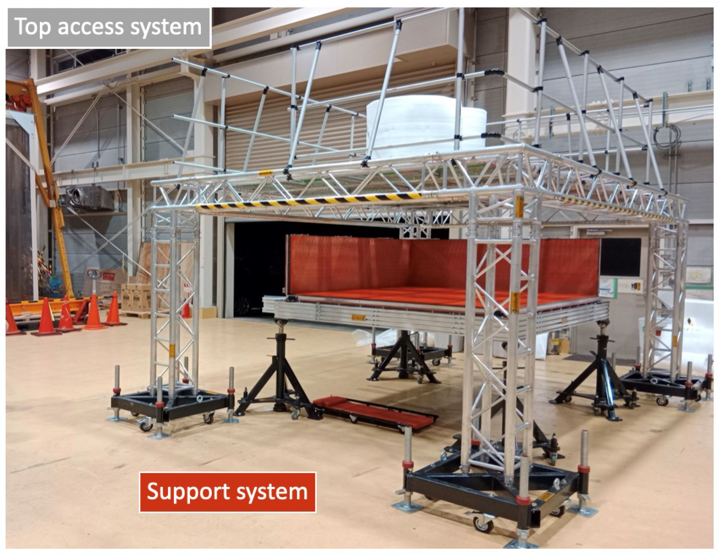
The SuperFGD assembly platform is a special equipment designed and constructed by the JINR group for the assembly of the SuperFGD with the possibility of unhindered access to all sides of the detector. The platform consists of two main parts: the top access system and the support system (see
Figure 12).
The top access system is a mechanical structure, consisting of a set of six frames with five mm removable floor cells in each. The frames are placed at an adjustable height, which provides access to the upper part of the SuperFGD. Access to the top system itself is provided by a ladder with a system of movement and fixation in a given position.
The support system is a power grid enclosed in a load-bearing frame mounted on four screw-adjustable elevators on wheels, which ensures the installation of the SuperFGD bottom panel and all four of its side panels with the possibility of moving them using installed power brackets, thus ensuring the fixation and retention of the detector at all stages of assembling and maintenance.
This platform and its components are designed to the SuperFGD mounting at the first stage: that is, the array of approximately 2 million scintillator cubes with 1 cm side, arranged in 56 horizontal planes of cubes each, is mounted in accordance with the assembling procedure, which is discussed below, as well as at the second stage: after closing the mechanical box, which includes the installation of WLS fibers, MPPC64–PCBs, LED calibration system and flexible cables for connecting the registration system.
At each stage of the SuperFGD assembling, the assembly platform and its components provide unhindered access to the detector from all sides, as well as reliable fixation of the detector in the correct spatial position at all stages of assembling and maintenance.
9.2. The First Stage of the SuperFGD Assembling
The SuperFGD assembly procedure was performed using the previously mounted assembly platform at J-PARC.
First of all, the installation of the bottom panel of the SuperFGD mechanical box with its fixation onto the support system was carried out. Following this, two side panels, namely the left and the upstream panels with a rigid angle of 90 degrees between them, were also installed on the support system in the area of the movement system of the brackets.
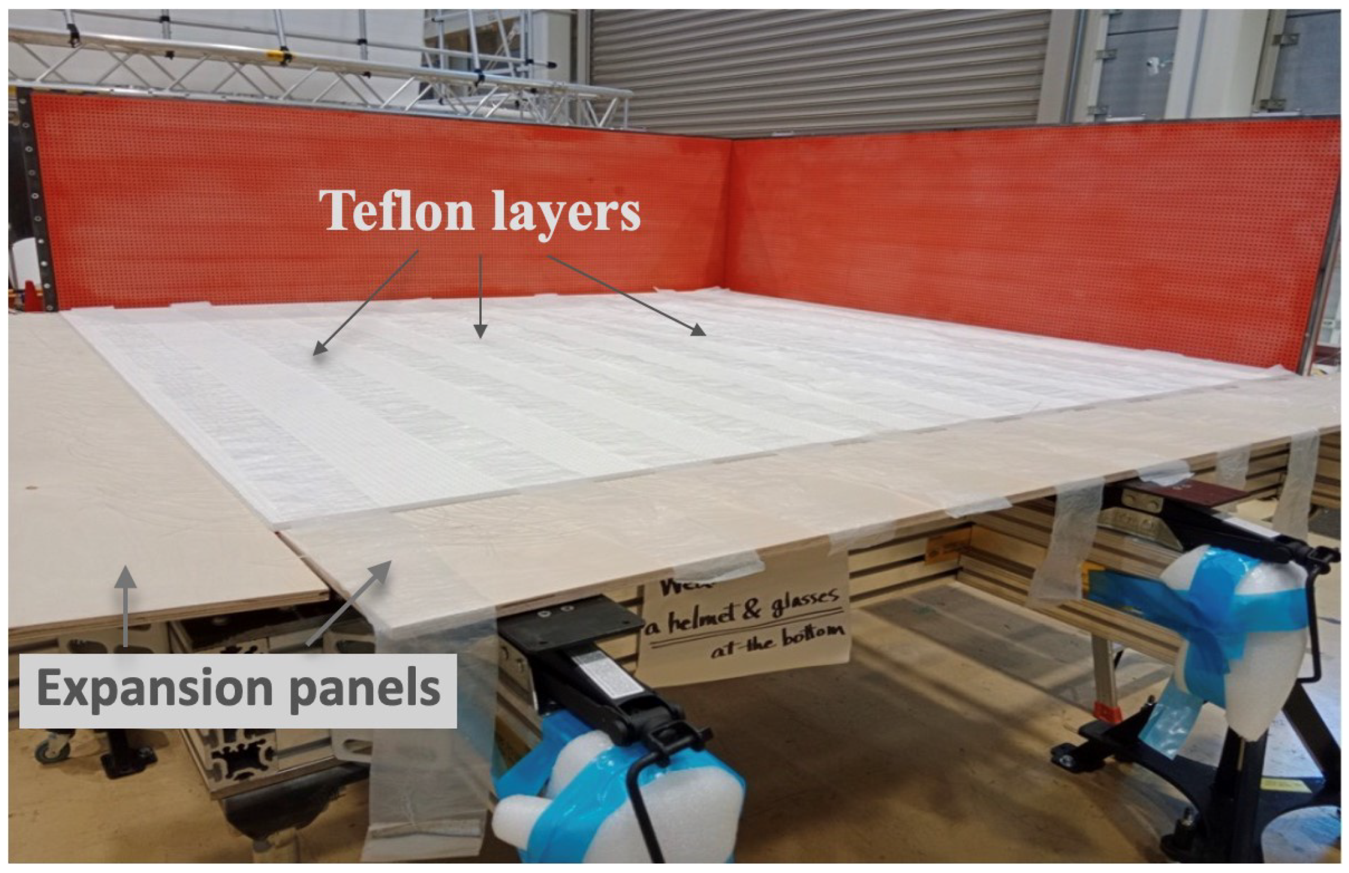
The next stage is the procedure of sequentially stacking 56 SuperFGD layers of
cubes each, assembled with horizontal fishing lines, on the bottom panel of the box. For this purpose, 10 teflon strips were prepared and rolled out on the bottom panel, and 2 expansion panels were installed on the open sides of the box to provide additional sliding of the SuperFGD layers when they are stacked on top of each other, as shown in
Figure 13.
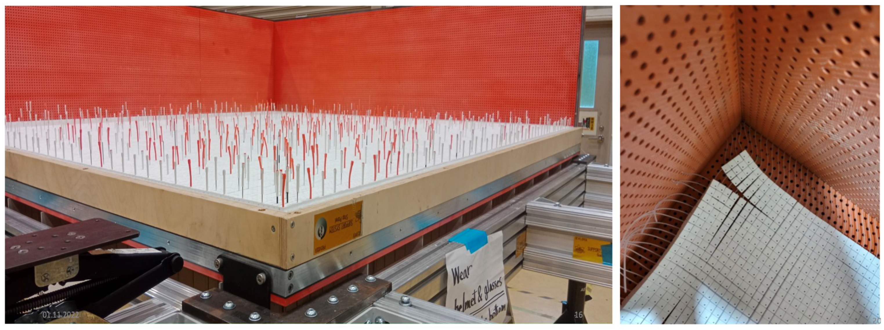
After these preparations, the first SuperFGD layer was placed on the bottom panel from the open sides of the box at the distance of 4–5 cm from the two side panels that are already mounted. When all fishing lines matched the box holes, this layer was pushed to the rigid corner of the box, as shown in
Figure 14. This procedure is the same for all layers. In addition, each two layers of the SuperFGD cubes were aligned vertically using about 1000 ⌀1.3 mm steel spokes. Every six layers were fixed vertically with stop wooden panels (see
Figure 13), with the exception of the first five SuperFGD layers, which were used to check the safety of the fishing lines during the detector assembly.
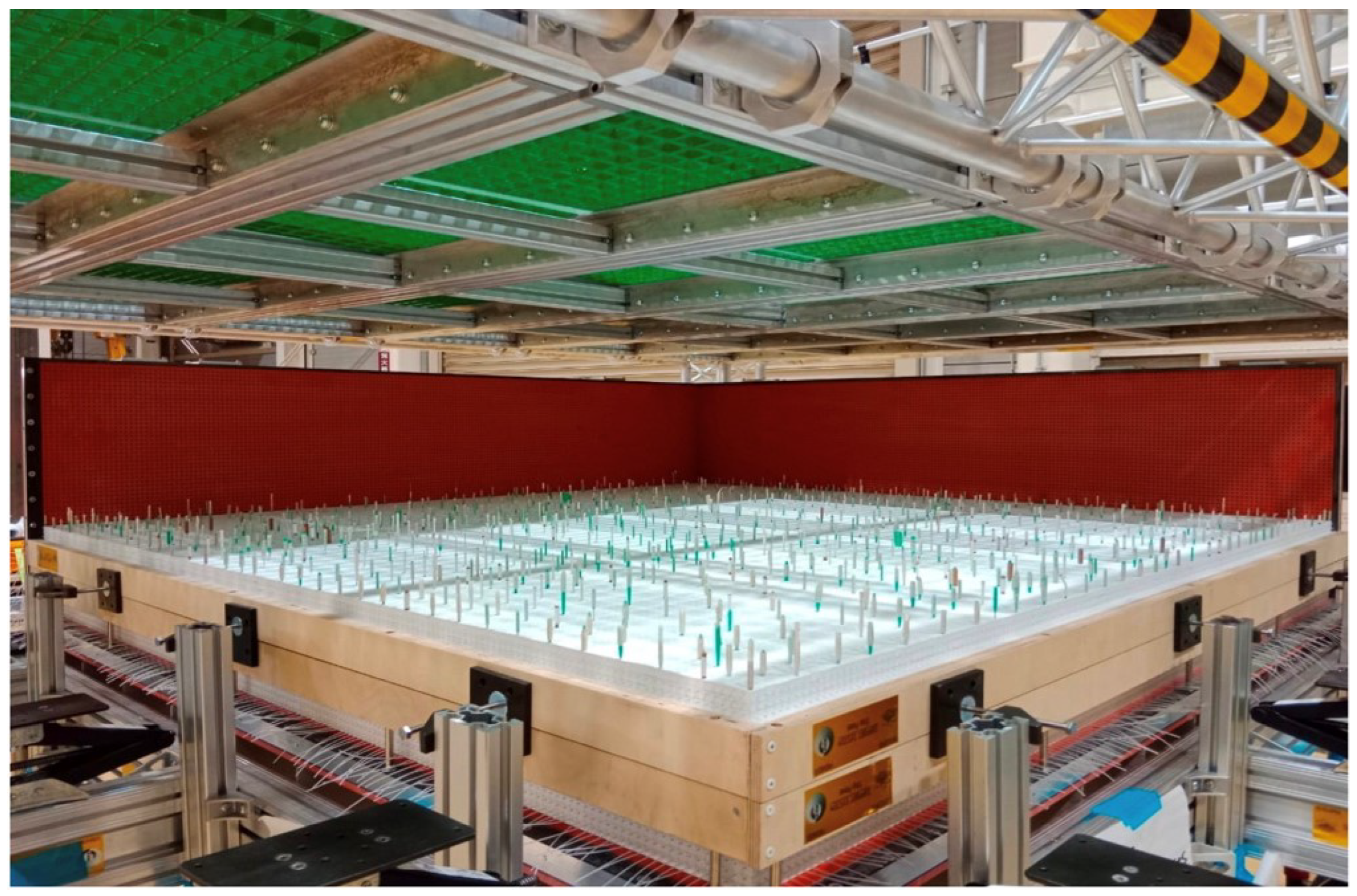
In addition, the preliminary result of the assembly of the SuperFGD is shown in
Figure 15.
Eventually, the assembly of all 56 layers of the SuperFGD cubes was completed, and the SuperFGD box was successfully closed with all of the cubes inside. At the same time, vertical alignment of the whole detector using about 12,000 welding rods with a diameter of 1.2 mm and a length of 94 cm was performed.
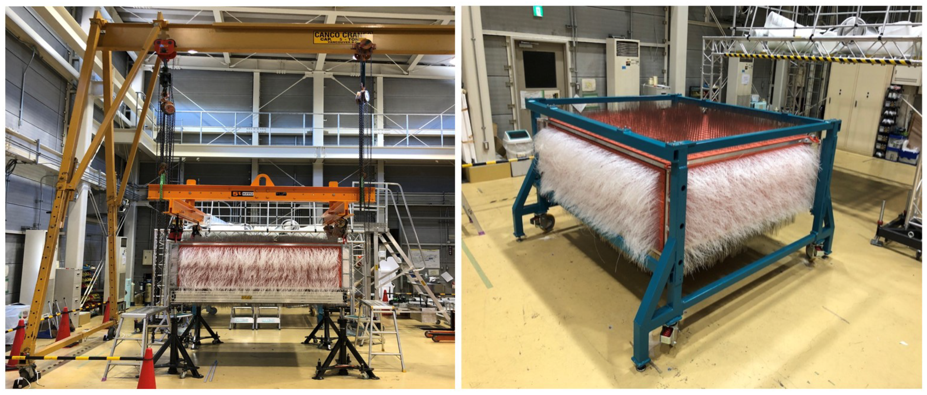
After that, the detector, consisting of the SuperFGD cubes inside the mechanical box, was dismantled from the support system using crane equipment and a specialized lifting device, such as a traverse, and installed into the mini Baby-Basket frame, which is shown in
Figure 16.
9.3. The Second Stage of the SuperFGD Assembling
Next, the detector was prepared for the second stage of assembly, that is, for the installation of electronics, mechanics, WLS fibers and the LED calibration system.
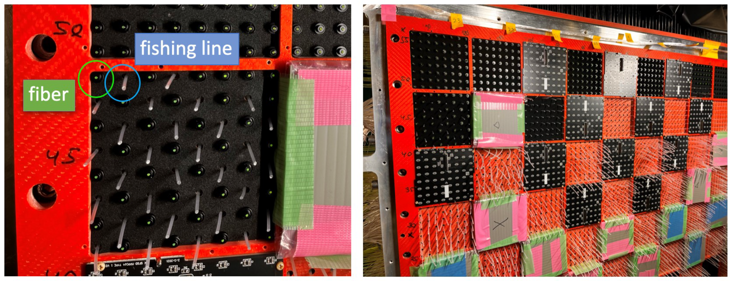
First of all, the installation of horizontal and vertical ⌀1 mm WLS fibers instead of fishing lines and welding rods, respectively, was carried out. During the manufacture of the SuperFGD mechanical box, all six faces of the SuperFGD were divided into cells with 64 holes in each, which corresponds to the size of a single PCB with 64 MPPC channels. The insertion of WLS fibers was carried out from the MPPCs side, while the removal of the fishing lines was carried out from the opposite side, designed for the integration of the LED calibration system.
The principle of inserting horizontal fibers from the upstream panel is demonstrated in
Figure 17.
On the removal side, the first group of 32 fishing lines was removed according to the chessboard scheme (see
Figure 17) in the
unit of through holes at the PCB level, without waiting for the insertion of the WLS fibers from the opposite side. Whereas, in the case of the second group of 32 fishing lines, the work on replacing them with WLS fiber was carried out one-by-one. The replacement of the welding rods with the optical WLS fibers in the vertical direction using the top access system was also carried out.
After installation, each WLS fiber was subjected to a quality control according to the criterion of emitting at least 70% of the total light absorbed by the fiber. For this purpose, a LED source, illuminating the ends of 64 WLS fibers cut off after their installation at a distance approximately of 5 mm from the wall of the SuperFGD mecanical box, and the PCB were used from opposite sides of the SuperFGD. As a result, out of the tested about 21,000 fibers in the horizontal direction (which corresponds to 329 PCBs), 21 fibers were discarded, and in the vertical direction out of about 35,000 fibers (552 PCBs), 42 fibers were determined to be of poor quality. The discarded fibers were replaced with new ones, followed by quality control.
After that, the attachment of the MPPC64–PCBs and the LED calibration system, with previously re-cutting of the ends of the WLS fibers, to the SuperFGD mechanical box surface was finished (see
Figure 18).
The next stage of the SuperFGD assembly consisted in closing the detector from all sides with a light barrier and installing 881 cables. The total weight of the detector, consisting of SuperFGD cubes and the box, is about 2.5 tons.
10. Conclusions
The ND280 upgrade is aimed at reducing systematic uncertanties at the far detector SuperKamiokande in the T2K experiment to 3–4% in order to improve its sensitivity to .
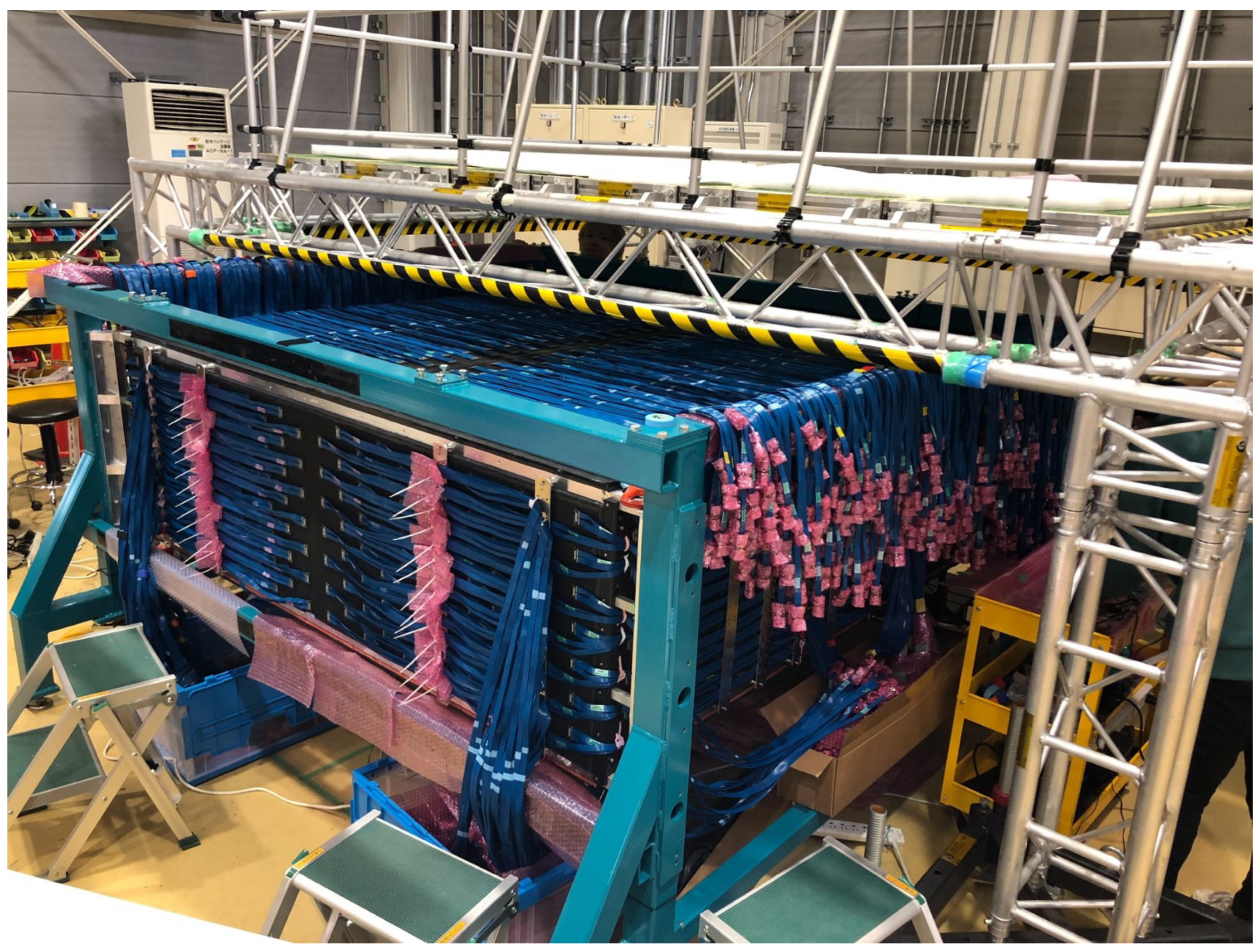
For this purpose, the novel fully active neutrino detector SuperFGD, which is the main part of the new upstream tracker of the off-axis ND280, has been developed. Currently, the assembly of the SuperFGD is actively carried out at J-PARC, in Japan. At present, the mechanical box with the SuperFGD cubes inside with already inserted WLS optical fibers, LED calibration system, PCBs, light barrier and with attached cables are fixed into the mini Baby-Basket (see
Figure 19). Tests with electronics for the SuperFGD are being conducted now, including global DAQ (data acquisition) integration tests and surface tests with MPPCs.
The T2K Collaboration expects to have a neutrino beam approximately at the beginning of November 2023. The exact time period is to be decided at the end of summer 2023. The milestones on the SuperFGD are the following: installation of the bottom and the downstream TOF panel and arrival of the first half of the SuperFGD electronics at J-PARC—July 2023; arrival of the bottom TPC and the second half of the SuperFGD electronics at J-PARC—August 2023; commissioning of the SuperFGD electronics at J-PARC on surface is planned at the end of August 2023. The commissioning of the fully upgraded off-axis ND280 is considered to be an important task in the calendar year 2024.
Author Contributions
Conceptualization, S.F., Y.K. and A.M.; Methodology, M.K., A.K., O.M. and N.Y.; Software, A.K. and A.M.; Validation, A.M. and O.M.; Formal analysis, A.D., D.C., A.C., G.E., D.F., S.F. and A.K.; Investigation, D.C., A.C., G.E., D.F., S.F., M.K. and N.Y.; Data curation, A.D, A.K. and A.M.; Writing–original draft, A.D.; Writing–review and editing, Y.K, O.M. and A.K.; Visualization, A.D.; Supervision, S.F., Y.K. and A.M.; Project administration, Y.K. All authors have read and agreed to the published version of the manuscript.
Funding
This work was supported in part by RSF (Russian Science Foundation) grants numbers 19-12-00325 and 22-12-00358.
Data Availability Statement
The data can be obtained from the references cited.
Acknowledgments
We wish to thank members of the T2K experiment for the cooperation and valuable discussions.
Conflicts of Interest
The authors declare no conflict of interest.
References
- Abe, K. et al. [T2K Collaboration]. The T2K experiment. Nucl. Instrum. Meth. Phys. Res. A. 2011, 659, 106–135. [Google Scholar] [CrossRef]
- Nakaya, T.; Nishikawa, K. Long baseline neutrino oscillation experiments with accelerators in Japan: From K2K to T2K. Eur. Phys. J. C 2020, 80, 344. [Google Scholar] [CrossRef]
- Kudenko, Y. The near neutrino detector for the T2K experiment. Nucl. Instrum. Meth. Phys. Res. A. 2009, 598, 289–295. [Google Scholar] [CrossRef] [Green Version]
- Abe, K.; Hayato, Y.; Iida, T.; Iyogi, K.; Kameda, J.; Kishimoto, Y.; Koshio, Y.; Marti, L.; Miura, M.; Moriyama, S.; et al. Calibration of the Super-Kamiokande detector. Nucl. Instrum. Meth. Phys. Res. A. 2014, 737, 253–272. [Google Scholar] [CrossRef] [Green Version]
- Fukuda, S. et al. [Super-Kamiokande Collab.]. The Super-Kamiokande detector. Nucl. Instrum. Meth. Phys. Res. A. 2003, 501, 418–462. [Google Scholar] [CrossRef]
- Hayato, Y. T2K at J-PARC. Nucl. Phys. B Proc. Suppl. 2005, 143, 269–276. [Google Scholar] [CrossRef]
- Abe, K. et al. [The T2K Collaboration]. Measurements of the T2K neutrino beam properties using the INGRID on-axis near detector. Nucl. Instrum. Meth. Phys. Res. A. 2012, 694, 211–223. [Google Scholar] [CrossRef] [Green Version]
- Abe, K. et al. [The T2K Collaboration]. Constraint on the matter-antimatter symmetry-violating phase in neutrino oscillations. Nature 2020, 580, 339–344. [Google Scholar] [CrossRef] [Green Version]
- Abe, K. et al. [T2K Collaboration]. Observation of electron neutrino appearance in a muon neutrino beam. Phys. Rev. Lett. 2014, 112, 061802. [Google Scholar] [CrossRef] [Green Version]
- Abe, K. et al. [T2K Collaboration]. T2K ND280 upgrade—Technical Design Report. arXiv 2019, arXiv:1901.03750. [Google Scholar] [CrossRef]
- Assylbekov, S.; Barr, G.; Berger, B.E.; Berns, H.; Beznosko, D.; Bodek, A.; Bradford, R.; Buchanan, N.; Budd, H.; Caffari, Y.; et al. The T2K ND280 off-axis pi-zero detector. Nucl. Instrum. Meth. Phys. Res. A. 2012, 686, 48–63. [Google Scholar] [CrossRef] [Green Version]
- Abgrall, N.; Andrieu, B.; Baron, P.; Bene, P.; Berardi, V.; Beucher, J.; Birney, P.; Blaszczyk, F.; Blondel, A.; Bojechko, C.; et al. Time projection chambers for the T2K near detectors. Nucl. Instrum. Meth. Phys. Res. A. 2011, 637, 25–46. [Google Scholar] [CrossRef] [Green Version]
- Amaudruz, P.A.; Barbi, M.; Bishop, D.; Braam, N.; Brook-Roberge, D.G.; Giffin, S.; Gomi, S.; Gumplinger, P.; Hamano, K.; Hastings, N.C.; et al. The T2K fine-grained detectors. Nucl. Instrum. Meth. Phys. Res. A. 2012, 696, 1–31. [Google Scholar] [CrossRef] [Green Version]
- Aoki, S.; Barr, G.; Batkiewicz, M.; Błocki, J.; Brinson, J.D.; Coleman, W.; Dąbrowska, A.; Danko, I.; Dziewiecki, M.; Ellison, B.; et al. The T2K Side Muon Range Detector (SMRD). Nucl. Instrum. Meth. Phys. Res. A. 2013, 698, 135–146. [Google Scholar] [CrossRef] [Green Version]
- Korzenev, A.; Barao, F.; Bordoni, S.; Breton, D.; Cadoux, F.; Favre, Y.; Khabibullin, M.; Khotyantsev, A.; Kudenko, Y.; Lux, T.; et al. A 4π time-of-flight detector for the ND280/T2K upgrade. J. Instrum. 2022, 17, P01016. [Google Scholar] [CrossRef]
- Mineev, O.; Fedotov, S.; Khotjantsev, A.; Korzenev, A.; Kudenko, Y.; Mefodiev, A.; Noah, E.; Sgalaberna, D.; Smirnov, A.; Yershov, N. Parameters of fine-grained scintillator detector prototype with 3D WLS fiber readout for T2K ND280 neutrino active target. Nucl. Instrum. Meth. Phys. Res. A. 2019, 936, 136–138. [Google Scholar] [CrossRef]
- Blondel, A.; Cadoux, F.; Fedotov, S.; Khabibullin, M.; Khotjantsev, A.; Korzenev, A.; Kostin, A.; Kudenko, Y.; Longhin, A.; Mefodiev, A.; et al. A fully-active fine-grained detector with three readout views. J. Instrum. 2018, 13, P02006. [Google Scholar] [CrossRef] [Green Version]
- Dergacheva, A.; Khotjantsev, A.; Kudenko, Y.; Mefodiev, A. 3D SuperFGD detector for the T2K experiment. Nucl. Instrum. Meth. Phys. Res. A. 2022, 1041, 167219. [Google Scholar] [CrossRef]
- Fedotov, S.; Dergacheva, A.; Filik, A.; Khabibullin, M.; Khotjantsev, A.; Kudenko, Y.; Mineev, O.; Yershov, N. Scintillator cubes for 3D neutrino detector SuperFGD. J. Phys. Conf. Ser. 2020, 2374, 012106. [Google Scholar] [CrossRef]
- Mineev, O.; Blondel, A.; Favre, Y.; Fedotov, S.; Khotjantsev, A.; Korzenev, A.; Kudenko, Y.; Mefodiev, A.; Noah, E.; Sgalaberna, D.; et al. Beam test results of 3D fine-grained scintillator detector prototype for T2K ND280 neutrino active target. Nucl. Instrum. Meth. Phys. Res. A 2019, 923, 134–138. [Google Scholar] [CrossRef] [Green Version]
- Blondel, A.; Bogomilov, M.; Bordoni, S.; Cadoux, F.; Douqa, D.; Dugas, K.; Ekelof, T.; Favre, Y.; Fedotov, S.; Fransson, K.; et al. The SuperFGD Prototype charged particle beam tests. J. Instrum. 2020, 15, P12003. [Google Scholar] [CrossRef]
- CAEN. Electronuc Instrumentation WP2081. Digital Pulse Processing in Nuclear Physics. Rev. 3 (August 2011). Available online: https://docplayer.net/65344973-Caen-electronic-instrumentation-wp2081-digital-pulse-processing-in-nuclear-physics-rev-august-guide.html (accessed on 25 May 2023).
- Orme, D.; Nagai, N.; Minamino, A.; Nakaya, T.; Yokoyama, M.; Nakadaira, T.; Murakami, T.; Tanaka, M.; Retiere, F.; Vacheret, A.; et al. Development of multi-pixel photon counters for the T2K long base-line neutrino experiment. Nucl. Instrum. Meth. Phys. Res. A. 2010, 623, 321–323. [Google Scholar] [CrossRef]
- Hamamatsu. MPPCs (SiPMs)/MPPC arrays. Available online: https://www.hamamatsu.com/jp/en/product/optical-sensors/mppc/mppc_mppc-array.html (accessed on 25 May 2023).
- Cizel, J.-B. Citiroc 1A: Scientific Instrumentation SiPM Read-out Chip. Datasheet. Dec. 2019. Available online: https://www.weeroc.com/products/sipm-read-out/citiroc-1a (accessed on 25 May 2023).
- Munteanu, L.; Suvorov, S.; Dolan, S.; Sgalaberna, D.; Bolognesi, S.; Manly, S.; Yang, G.; Giganti, C.; Iwamoto, K.; Jesús-Valls, C. A new method for an improved anti-neutrino energy reconstruction with charged-current interactions in next-generation detectors. Phys. Rev. D 2020, 101, 092003. [Google Scholar] [CrossRef]
- Agarwal, A.; Budd, H.; Capó, J.; Chong, P.; Christodoulou, G.; Danilov, M.; Dergacheva, A.; De Roeck, A.; Dokania, N.; Douqa, D.; et al. Total neutron cross-section measurement on CH with a novel 3D-projection scintillator detector. Phys. Lett. B. 2023, 840, 137843. [Google Scholar] [CrossRef]
- Diab. Divinycell-PVC Core Materials. Available online: https://www.diabgroup.com/products-services/divinycell-pvc/ (accessed on 25 May 2023).
Figure 1.
Schematic view of the T2K experiment. See text for details.
Figure 1.
Schematic view of the T2K experiment. See text for details.
Figure 2.
The current view of the off-axis ND280 and its upgrade idea. See text for details.
Figure 2.
The current view of the off-axis ND280 and its upgrade idea. See text for details.
Figure 3.
View of the SuperFGD assembled with fishing line method. The fishing lines to be replaced by wavelength shifting (WLS) fibers later.
Figure 3.
View of the SuperFGD assembled with fishing line method. The fishing lines to be replaced by wavelength shifting (WLS) fibers later.
Figure 4.
(Left) distribution of the cube side length. A total of 513 cubes were measured in random order: one side per cube. The red curve represents the Gaussian fit. (Right) weight distribution of a single cube. The “ndf” denotes the degrees of freedom for the fit with the straight line with the parameter .
Figure 5.
Track of 0.5 GeV/c proton stopped inside the volume of the SuperFGD prototype ( cm) in a magnetic field of 0.2 T in two projections. The color of each bin shows the value of the light yield in photoelectrons in the corresponding cube of the SuperFGD prototype as indicated.
Figure 5.
Track of 0.5 GeV/c proton stopped inside the volume of the SuperFGD prototype ( cm) in a magnetic field of 0.2 T in two projections. The color of each bin shows the value of the light yield in photoelectrons in the corresponding cube of the SuperFGD prototype as indicated.
Figure 6.
(Left) US–Japan prototype with a size of cm assembled on fishing lines. (Right) US–Japan prototype in a mechanical case with attached cables.
Figure 6.
(Left) US–Japan prototype with a size of cm assembled on fishing lines. (Right) US–Japan prototype in a mechanical case with attached cables.
Figure 7.
The total neutron cross-section on hydro-carbon as a function of neutron kinetic energy [
27].
Figure 7.
The total neutron cross-section on hydro-carbon as a function of neutron kinetic energy [
27].
Figure 8.
(Left) printed circuit boards (PCBs) attachment on the surface of the SuperFGD mechanical box. (Right) two types of connector position of multi-pixel photon counters (MPPCs) on the PCB.
Figure 8.
(Left) printed circuit boards (PCBs) attachment on the surface of the SuperFGD mechanical box. (Right) two types of connector position of multi-pixel photon counters (MPPCs) on the PCB.
Figure 9.
(Left) general view of the LED calibration module with a light guide plate (LGP). (Right) LGP module distributes light from the LED source directly to the MPPCs.
Figure 9.
(Left) general view of the LED calibration module with a light guide plate (LGP). (Right) LGP module distributes light from the LED source directly to the MPPCs.
Figure 10.
A view of the mechanical box from the bottom side with the LGP modules attached to the box surface. Space for the LED part (in red) is oriented to the bottom corner for minimal interference with the box structure such as a bracket.
Figure 10.
A view of the mechanical box from the bottom side with the LGP modules attached to the box surface. Space for the LED part (in red) is oriented to the bottom corner for minimal interference with the box structure such as a bracket.
Figure 11.
Bottom (left) and side (right) LGP modules with a length of about 1 m and 0.6 m, respectively.
Figure 11.
Bottom (left) and side (right) LGP modules with a length of about 1 m and 0.6 m, respectively.
Figure 12.
The top access system and the support system of the SuperFGD-assembling platform at J-PARC.
Figure 12.
The top access system and the support system of the SuperFGD-assembling platform at J-PARC.
Figure 13.
Teflon strips on the bottom panel and two expansion panels on the open sides of the box for the better sliding of the SuperFGD layers.
Figure 13.
Teflon strips on the bottom panel and two expansion panels on the open sides of the box for the better sliding of the SuperFGD layers.
Figure 14.
(Left) several SuperFGD layers stacked on top of each other using a stop panel and a set of steel spokes. (Right) the first SuperFGD layer on the bottom panel of the mechanical box.
Figure 14.
(Left) several SuperFGD layers stacked on top of each other using a stop panel and a set of steel spokes. (Right) the first SuperFGD layer on the bottom panel of the mechanical box.
Figure 15.
Assembling of the SuperFGD layers.
Figure 15.
Assembling of the SuperFGD layers.
Figure 16.
(Left) the process of the SuperFGD transportation to the mini Baby-Basket using crane equipment and the lifting device. (Right) SuperFGD inside the mini Baby-Basket frame.
Figure 16.
(Left) the process of the SuperFGD transportation to the mini Baby-Basket using crane equipment and the lifting device. (Right) SuperFGD inside the mini Baby-Basket frame.
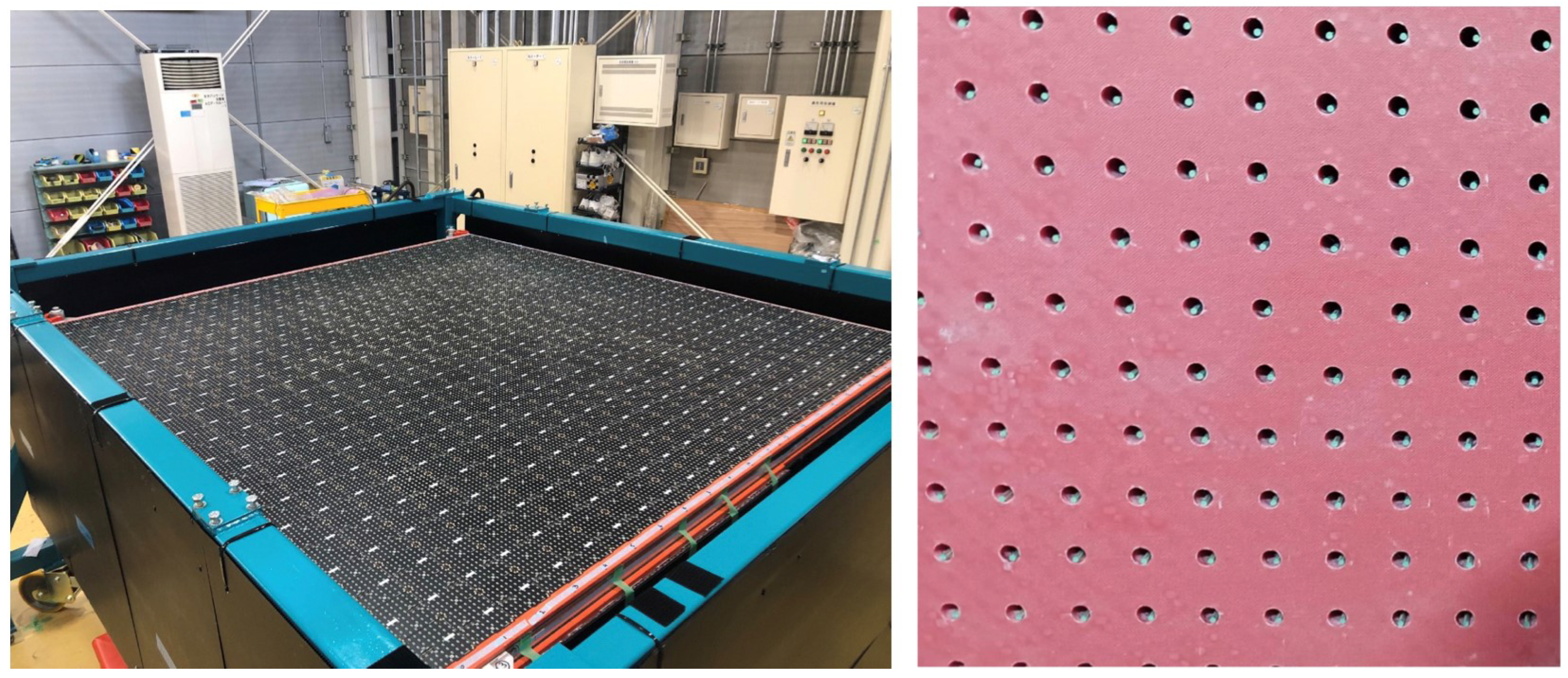
Figure 17.
(Left) a single unit of through holes on the upstream panel. (Right) general view of the upstream panel during the replacement of horizontal fishing lines with the WLS fibers.
Figure 17.
(Left) a single unit of through holes on the upstream panel. (Right) general view of the upstream panel during the replacement of horizontal fishing lines with the WLS fibers.
Figure 18.
(Left) top panel of the SuperFGD with the MPPC64–PCBs attachment. (Right) WLS fibers with cutting ends before the installation of the LED calibration system.
Figure 18.
(Left) top panel of the SuperFGD with the MPPC64–PCBs attachment. (Right) WLS fibers with cutting ends before the installation of the LED calibration system.
Figure 19.
The SuperFGD is closed by the light barrier with cables connected to it.
Figure 19.
The SuperFGD is closed by the light barrier with cables connected to it.
| Disclaimer/Publisher’s Note: The statements, opinions and data contained in all publications are solely those of the individual author(s) and contributor(s) and not of MDPI and/or the editor(s). MDPI and/or the editor(s) disclaim responsibility for any injury to people or property resulting from any ideas, methods, instructions or products referred to in the content. |
© 2023 by the authors. Licensee MDPI, Basel, Switzerland. This article is an open access article distributed under the terms and conditions of the Creative Commons Attribution (CC BY) license (https://creativecommons.org/licenses/by/4.0/).

 ,
, 


