Article

A Full Assistance System (FAS) for the Safe Use of the Tractor’s Foldable Rollover Protective Structure (FROPS)

1
Italian Workers’ Compensation Authority (INAIL), Monte Porzio Catone, 00078 Rome, Italy
2
Engineering Department, Universitas Mercatorum, 00186 Rome, Italy
*
Author to whom correspondence should be addressed.
AgriEngineering 2023, 5(1), 218-235; https://doi.org/10.3390/agriengineering5010015
Submission received: 16 December 2022 / Revised: 21 January 2023 / Accepted: 23 January 2023 / Published: 25 January 2023

Abstract

:
The use of agricultural tractors is a major concern in agriculture safety due to the high level of risk of loss of stability combined with the frequent absence of passive safety devices such as rollover protective structures (ROPSs). Indeed, although in most cases the ROPS is installed, when working in vineyards, orchards, or in other cases of limited crop height, the tractor is usually equipped with a foldable ROPS (FROPS), which is often misused because the effort needed for raising/lowering is excessive and the locking procedure is time-consuming. Thus, the goal of this research is to investigate the problem from the ergonomics point of view, developing a support system capable of facilitating FROPS operations. The research outcome consists of the development of a retrofitted full assistance system (FAS) for lowering/raising the FROPS by means of electric actuators. Additionally, an automatic locking device (ALD) was also developed to safely and automatically lock the FROPS. Both the FAS and ALD systems were implemented following a reverse-engineering approach, while their final validation was performed by means of a real prototype tested in a laboratory. The results achieved can contribute to expanding knowledge on human-centered research to improve safety in agriculture and thus social issues of sustainable agricultural systems.

1. Introduction

Putting them into practice, safety issues represent the operational command of sustainability [1], and occupational health and safety (OHS) initiatives aimed at reducing accidents represent the operationalization of sustainability in workplaces [2,3]. Accordingly, a human-centered approach to improve safety is regarded as a means to improve sustainable working systems [4]. In agricultural activities, although a decrease in accidents was registered in the last years, mainly due to the reduction in activities related to the COVID-19 pandemic, the number of injuries and fatalities is still great if compared to other sectors [5], as well as the occurrence of health diseases such as musculoskeletal disorders (MSDs) [6], and most severe injuries and fatalities concern the misuse of tractors [7]. In particular, the tractor’s rollover is reported as the main cause of fatalities [8,9], especially when the rollover protective structure (ROPS) had not been installed (e.g., in old vehicles) or when it was not correctly used. Actually, the ROPS is a roll bar that absorbs energy in the case of the tractor’s rollover, enabling a safety zone for the operator, which is called a “clearance zone”.
In Figure 1, two examples of two-post foldable ROPSs (FROPSs) for narrow-track tractors are shown: a rear-mounted FROPS on the left and a front-mounted FROPS on the right side of the figure.
To reduce such a phenomenon, different initiatives have been carried out worldwide [10], such as the updating of old tractors with ROPSs and seatbelts, which has been promoted in different countries by means of retrofitting campaigns [11,12,13], the issuing of technical guidelines [14,15], or training courses for farmers [16].
However, these initiatives hardly impact the misuse of foldable ROPSs; for example, when the foldable ROPS is disabled to better operate in vineyards, orchards, or in other cases of limited crop height and is not subsequently raised after this work. These situations are very common, as reported by numerous studies showing that up to 50% of fatalities are due to the misuse of foldable ROPSs [17,18,19].
According to occupational health and safety (OHS) guidelines, farmers can unfold the ROPS in cultivation work where there is a low clearance between the tractor and the vegetation (both in height and in width), but they should raise it again as soon as this specific work is completed. Instead, when operating in these environments, farmers usually keep it unfolded; such an unsafe behavior is very common and it is typically justified by farmers pointing out the excessive effort that they have to make to fold/unfold the ROPS several times in a work day [20,21]. It must be noted that the tractors used most in these operations are narrow-track models, which can be defined per Molari and Rondelli [22] as a tractor that, when equipped with tires of the greatest allowed dimensions, “has a minimum track width of not more than 1150 mm”.
The ergonomics literature has provided different approaches to deal with this problem: for example, Cremasco et al. [23] developed and tested a prototype solution to increase FROPS reachability, which consists of a rod that allows the users to raise a two-post rear-mounted FROPS more easily, respecting anthropometric variability. Differently, Etherton et al. [24] developed a telescoping structure for an automatically deployable ROPS. Similarly, Alkhaledia et al. [25] proposed an automatically foldable protective structure, which resulted in a very effective solution to protect the operator. The development of automatic solutions was investigated also by Ballesteros et al. [19], who proposed an automatically deployable (both in height and width) ROPS. All these mechanical solutions are noteworthy from the technical point of view, but often they are inconvenient from the financial one, especially in the case of upgrading old tractors. Moreover, they scarcely analyze the ergonomic issues, which leads to discomfort for the farmer when operating the ROPS. As remarked by recent studies [20,26] on this topic, further research is needed to make the ROPS’s lowering/raising more comfortable. Such an address was followed by Gattamelata et al. [27], who discussed the development of a partial assistance system (PAS) to reduce the operator’s physical effort: on the one hand, this system can improve the usability of the FROPS because it reduces the loads in lowering/raising operations by means of springs; on the other hand, such a solution represents a partial solution to reduce the operator’s discomfort and further analysis is needed to optimize the configuration and implement a safe locking system to practically increase the FROPS’s usability. In fact, although decreasing the operator’s stress in lowering/raising operations, such a solution does not avoid manual handling, which is the most common cause of FROPS misuse.
Hence, the goal of the current study is to expand the research outputs of Gattamelata et al. [27], focusing on the following issues:
  • The development of a full assistance system (FAS) by means of strength analysis;
  • The development of a system that can automatically lock the FROPS when it is unfolded without making the folding operations strenuous;
  • The constructive and dynamic integration of this automatic locking device (ALD) with the FAS;
  • The physical testing of the prototype.
The remainder of the article is organized as follows: in Section 2, the research approach is summarized, starting with the preliminary analysis related to the FROPS’s lowering/raising operations, which is illustrated in Section 3, providing the input criteria used for the design activities. In Section 4, the concrete experience analysis is summarized. Then, in Section 5, the design of the FAS is proposed, while in Section 6, the development of the ALD is addressed. Section 7 shows the results of both the virtual and practical prototyping of these systems. Section 8 discusses the outcomes of the study, while Section 9 contains conclusive remarks.

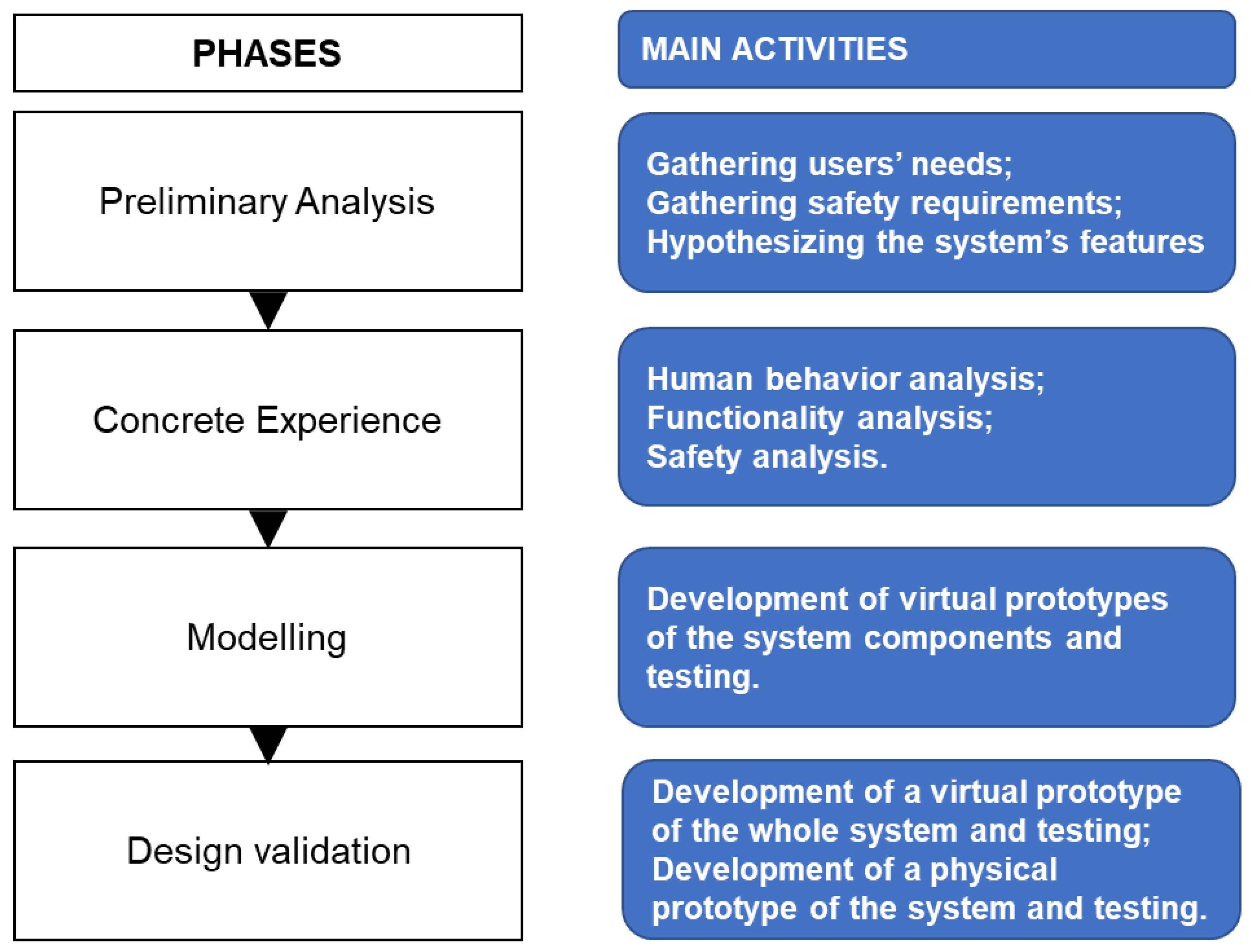
2. Research Approach

The development of the FAS and ALD system was carried out following a reverse-engineering approach, combining design for safety and ergonomics tools with a bottom-up approach [28]. As underlined by Wood et al. [29], such an approach mainly relies on the following activities:
  • Predicting the system behavior;
  • Predicting human behavior;
  • Analyzing the system functions;
  • Analyzing the users’ behavior;
  • Developing solution principles and the associated functions of the system;
  • Developing a virtual model and validating it;
  • Developing a physical prototype and validating it.
More in detail, the flow of activities that should be carried out can be schematized as in Figure 2. Needless to say, for each activity, the tools used to perform it can vary depending on the case context and engineers’ needs.

3. Preliminary Analysis

As previously mentioned, the most common tractor types equipped with foldable ROPS are those that can operate where there is a low clearance between the tractor and the vegetation, i.e., the narrow-track tractors, whose main features based on the OECD Codes are the following [30]:
  • A ground clearance not higher than 600 mm considering the lowest points of the axles;
  • A minimum track width with one of the axles less than 1150 mm when the tractor is equipped with tires or tracks of the largest size recommended by the manufacturer;
  • The unladen mass of the tractor, which can vary from 400 kg up to 3500 kg.
Moreover, the OECD Codes provide information on the ergonomic features of the foldable ROPS such as the criteria that must be used to measure loads in manual raising and lowering operations [27]. In such a context, useful definitions to determine the geometrical characteristics of these operations are:
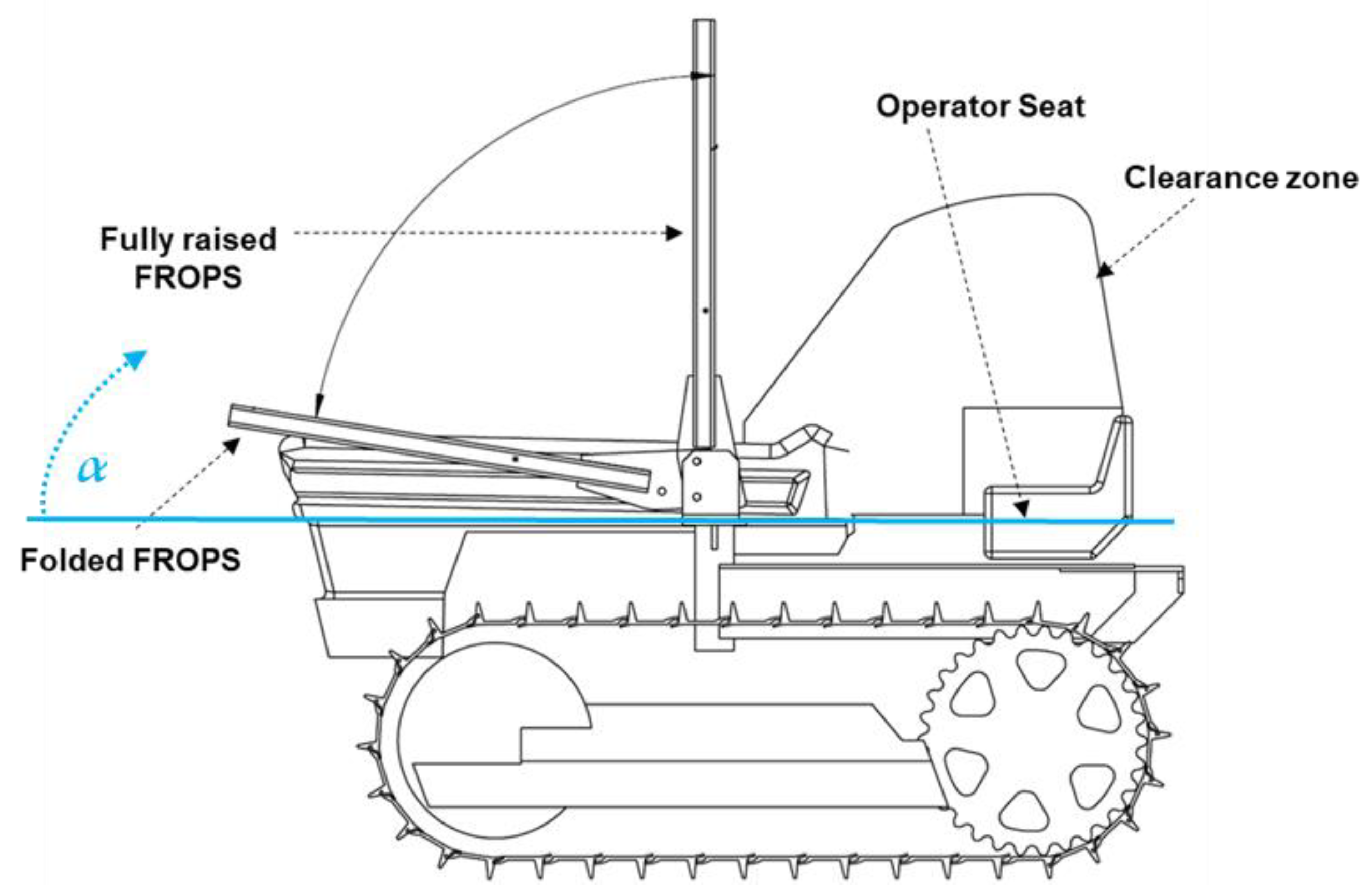
  • “Grasping area”, which is the part of the FROPS used by the operator to raise/lower the bar;
  • “Accessible part of the grasping area”, which represents the area that can be reached by the operator when raising/lowering the FROPS;
  • “Accessible zone”, consisting of the volume occupied by a standing operator when raising/lowering the FROPS.
Accordingly, the OECD Codes [30] indicate the acceptable force limits for raising/lowering operations, which can vary based on the different accessible zones: with reference to Figure 3, the acceptable force limit is:
  • For zone I, 100 N;
  • For zone II, 75 N;
  • For zone III, 50 N.
These values can also vary based on the different operations: for example, an increase in the force limits of up to 50% is allowed for lowering operations, and when the FROPS is fully raised or fully lowered, the force limit can be augmented by up to 25%. However, these indications are not sufficient at a practical level due to the variability of the operators and their real positioning when grasping the FROPS [23], which increases the efforts needed to operate the bar, leading to its misuse when working in fields. These criticalities have been brought forward by different researchers [31,32,33], who agree on the need to develop more human-centered solutions to reduce FROPS misuse. For the purpose of this study, a narrow-track tracklaying tractor equipped with a front-mounted two-post FROPS was used (Figure 4). It must be noted that in this figure, α represents the folding angle, and the rest configuration of the FROPS (folded FROPS) does not correspond to α = 0 because of the constructive features of the tractor’s bonnet. Actually, such features are very common for tracklaying tractors equipped with front-mounted FROPSs.

4. Concrete Experience

Following the proposed approach, a practical analysis of the ergonomics features of the FROPS’ use was carried out involving five tractor users to better define the dynamics and geometrical characteristics of raising/lowering operations practically. Each operator was asked to fold/unfold the FROPS several times, allowing us to register the body position and the handling points.
From the analysis of the raising/lowering operations, it emerged that the effort needed by the user to overwhelm the weight force of the FROPS when unfolding it and to maintain the bar when folding it is higher than the force limits foreseen by the OECD Codes. These results are in line with previous studies [31,34], showing that the risk of misuse of the FROPS is very high on the one hand, and the risk of musculoskeletal diseases should also be taken into account on the other, since raising/lowering operations might be repeated several times daily. Actually, it has to be considered that the weight of the FROPS is about 72 kg, while the roll bar height reaches 1210 mm, as per Gattamelata et al. [27].
Moreover, another issue that is scarcely treated in the extant literature is related to the risks that the operator is exposed to if the FROPS locking/unlocking operations are not performed correctly. In fact, to block the FROPS, two pins have to be used by the operator, who needs to walk around the tractor and fix them on both sides. These operations can contribute to FROPS misuse since additional physical efforts and a waste of time from the production point of view are required. Furthermore, the risk of entanglement and the risk deriving from the incorrect locking of the roll bar should also be considered.
Based on these considerations, the use of a full assistance system (FAS) that can support the operator in the FROPS raising operations, on the one hand, and the inclusion of an automatic locking device (ALD) to block the bar when fully raised, on the other, can certainly reduce the above-mentioned risks. The development of these safety devices was carried out considering their applicability to both new vehicles and old ones, i.e., the retrofitting of tractors already in use.

5. Modeling the Full Assistance System

The selection of the model was made considering the most diffused components and mechanical systems available on the market: it was found that the assistance system can be a linear or a rotating actuator, which acts on the FROPS, supporting its rotation with respect to the hinge joint. We decided to implement a linear actuator, as illustrated in Figure 5.
This choice is motivated by the fact that the FAS we are developing should be destined for the ROPS retrofit as well, limiting the costs that farmers have to bear for this type of upgrade. Accordingly, the electric linear actuator can be easily supplied by the tractor battery, and for this reason, it is much cheaper than a hydraulic or pneumatic system.
The dynamic analysis of the FROPS was based on the results of the ergonomic study proposed by Gattamelata et al. [27] and was aimed at evaluating the forces involved in the operation of folding/raising by means of the linear actuator. More in detail, the following moments were defined:
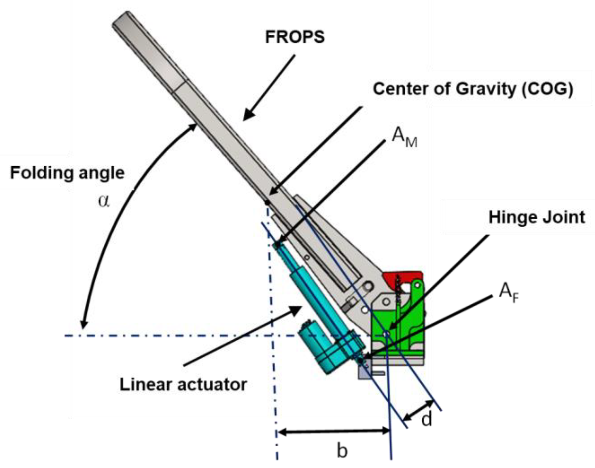
  • MW is the moment of the weight force of the FROPS: this moment varies depending on the horizontal distance of the center of gravity (GOC) from the axis of the hinge joint;
  • MACT represents the moment of the actuator, which varies on the basis of both the actuator type and the forces it can exert on the FROPS, considering the distance between the anchorage points AF (fixed anchorage point) and AM (mobile anchorage point) on the one hand, and the hinge axis to determine the arm lever on the other.
Accordingly, during the lowering/raising phase, MACT should be greater than the moment of the weight force, and the expression (1) must be satisfied:
MACT ≥ MW
The moment of the weight force MW can be determined by means of Equation (2) considering the folding angle α:
Mw = P × b × cos (α)
  • where P is the weight force of the FROPS, b is the arm of the weight force, and α represents the inclination of the FROPS (i.e., the folding angle), as schematized in Figure 5. It must be noted that MW reaches its maximum value in the rest configuration, and based on the data provided by [27], this value is about 187 Nm for each side.
  • The design of a suitable FAS requires an iterative procedure consisting of three main steps:
  • Step 1—identification of the actuator model in terms of strength (FACT) and stroke (i.e., the maximum and minimum distance between AF and AM allowed by the system);
  • Step 2—definition of the AF point on the FROPS’s fixed part and of AM on the FROPS’s mobile part;
  • Step 3—analysis of the load capability condition (MACT (α) ≥ MW).
It is noteworthy that in the second step, to allow an easy retrofit, a graphical procedure can be used that mimics the actuator behavior to find the position of the fixed and mobile hinge points without complex geometric calculations. Such a procedure is summarized in Figure 6 through three phases:
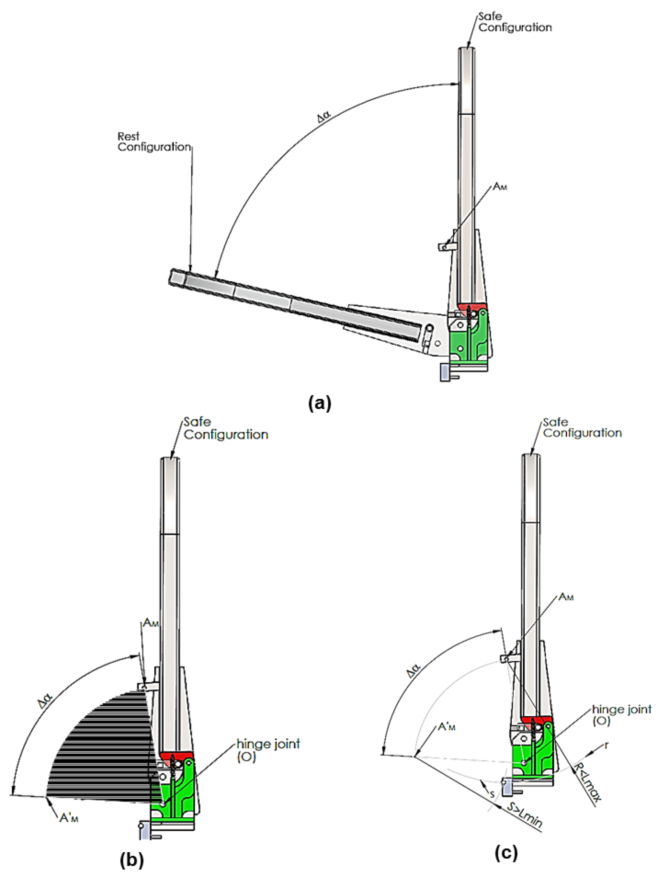
  • Phase 1: Evaluation of the angular range of motion of the FROPS, i.e., the span between the rest configuration (FROPS folded down) and safety configuration (FROPS fully raised); definition of the point AM;
  • Phase 2: Definition of the position of AM in the rest configuration (A’M) considering the sector of the circumference with the center corresponding to the projection of the hinge joint O (the amplitude corresponds to the angle ∆α);
  • Phase 3: Point AF of the actuator can be obtained as the intersection between the two circular arcs r and s, where s is the circumference arc centered at point AM (radius S), while r is the circumference arc centered in A’M (radius R). The anchorage points comply with the actuator range of motion only if R is smaller than the maximum elongation of the actuator Lmax and S is smaller than the minimum elongation of the actuator Lmin. If the actuator length and elongation do not meet these geometrical requirements, the AM point or/and the AF point should be changed iteratively.
Finally, it must be observed that step 3 concerns the dynamic validation of the actuator: if Equation (1) is not satisfied, it is necessary to restart the procedure with another actuator model. In this study, considering the inertia and dimensions of the prototype, and to be in compliance with Equation (1), an electric actuator with the following characteristics was chosen:
  • Nominal stroke: 152.4 mm;
  • Voltage: 12 V DC;
  • Current draw: 20 Amp;
  • Speed: 33 mm/sec;
  • Load: up to 18,000 N.

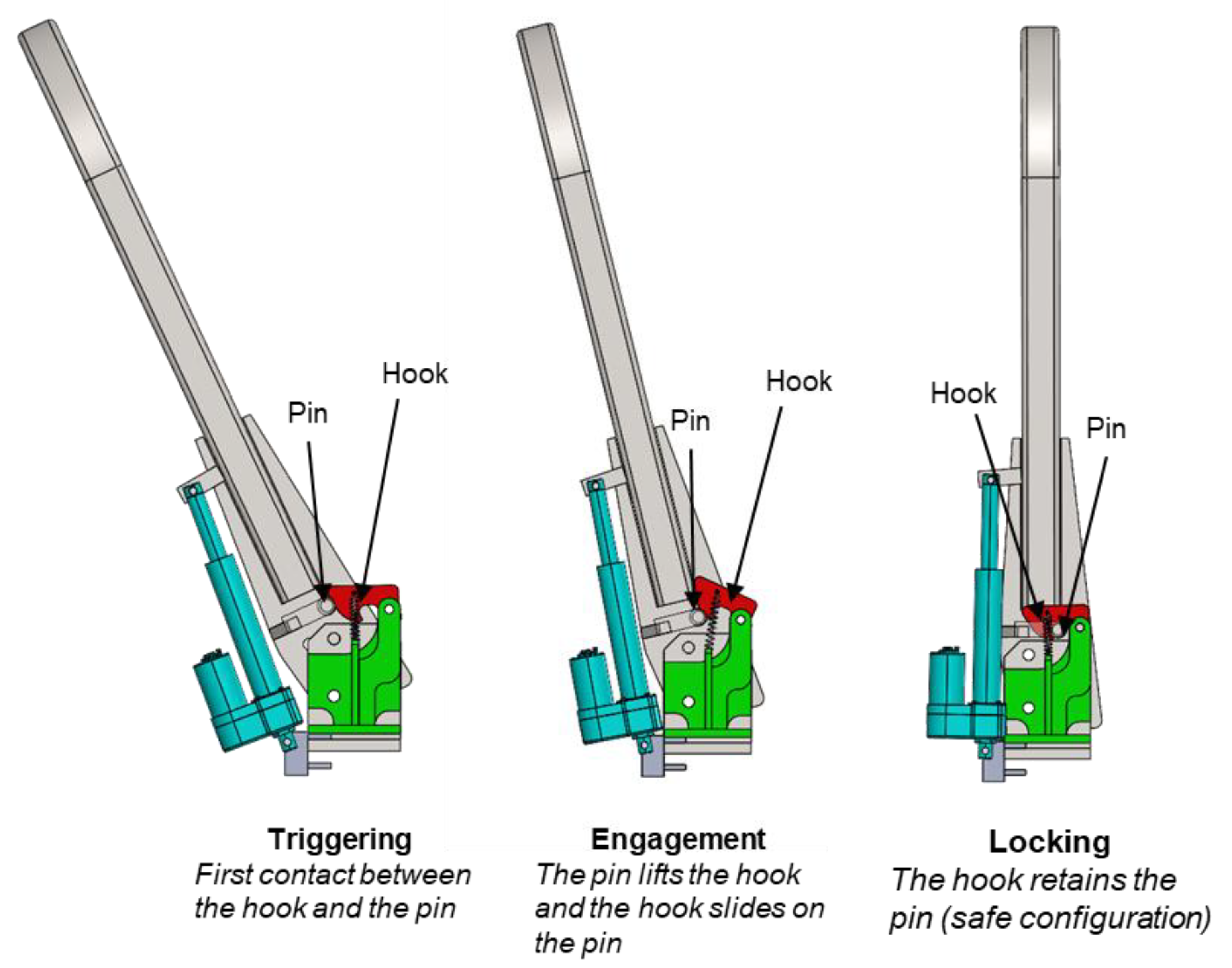
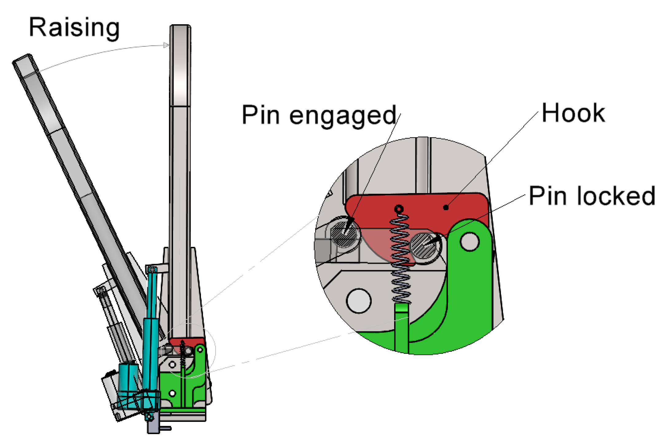
6. Modeling the Automatic Locking Device

The presence of a full assistance system to raise the FROPS eliminates the need to manually operate it, but in order to ensure the operator’s safety in case of a rollover, the FROPS must be locked in a safe configuration. The locking phase is usually made by the operator, who has to insert the pins in the locking holes on both sides of the tractor. The implementation of an automatic locking device (ALD) can avoid these operations and the risk of misusing the locking device. To achieve such a goal, it should be taken into account that an ALD must guarantee both safe locking and suitable structural resistance. These requirements, together with the need to keep the costs of the device at a feasible level, led us to implement a mechanical solution, capable of locking the roll bar automatically at the end of the raising phase and withstanding the loads deriving from the potential impact with the ground in case of a rollover. For these reasons, the ALD is preliminarily virtually prototyped to perform kinematic, dynamic, and strength analyses. Once the virtual model of the ALD satisfies all the performance requirements, a physical prototype will be developed and installed on a FROPS in order to carry out experimental tests of the whole system in accordance with the OECD Codes. In Figure 7, the model of this device assembled with the FAS is shown, describing its functionality that consists of three main phases:
  • Triggering;
  • Engagement;
  • Locking.

7. Validation

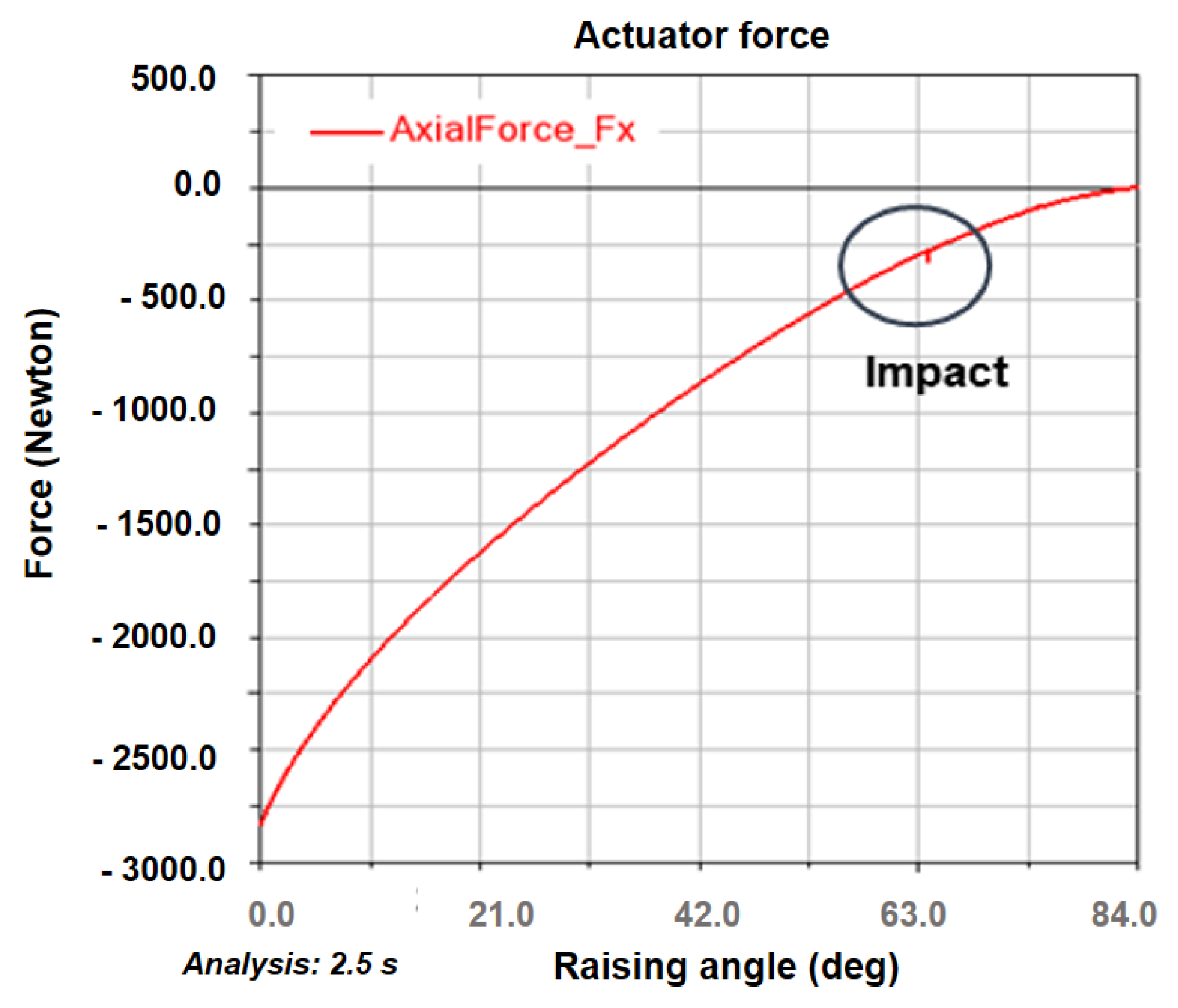
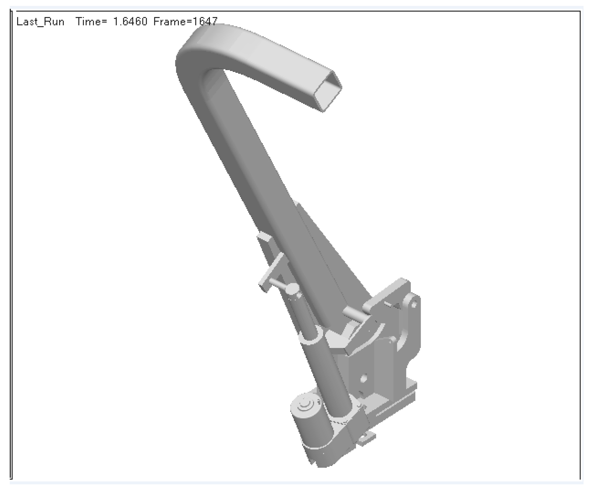
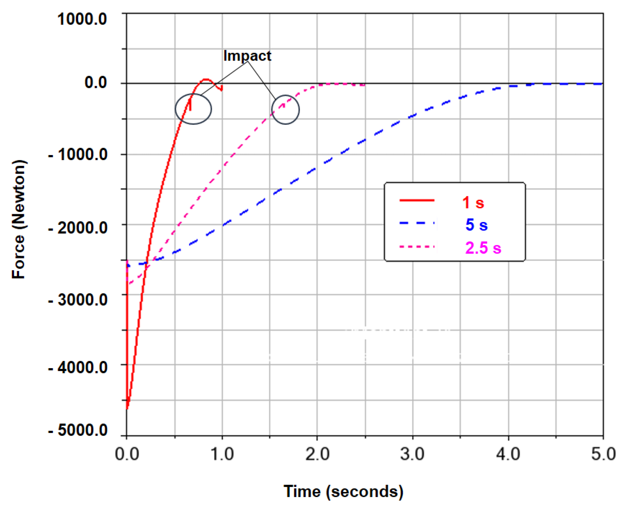
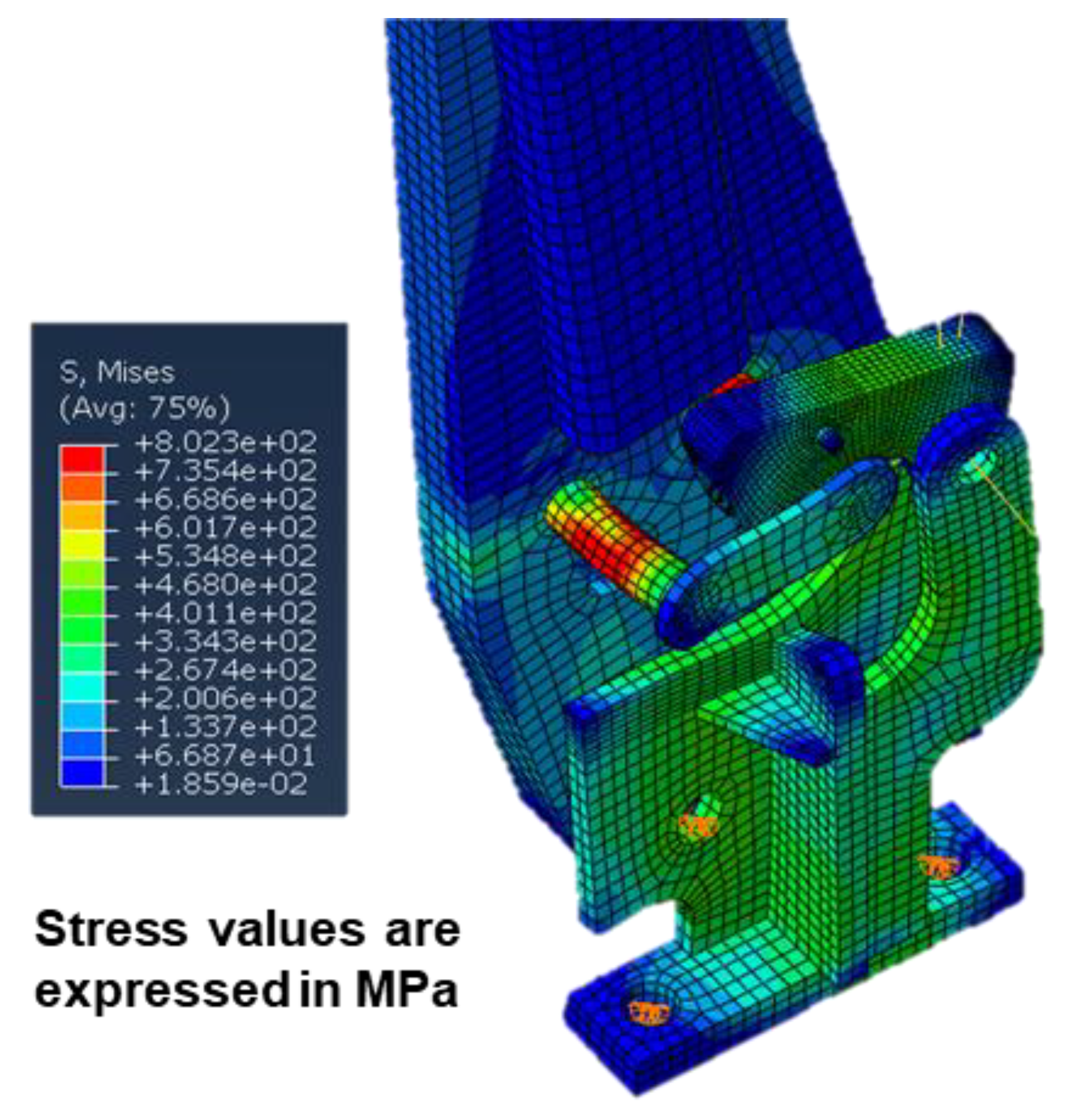
7.1. Virtual Testing

Once the geometrical features are defined, the whole system integrating both the FAS and the ALD was developed virtually to test its kinematical and dynamic features. Actually, dynamic analyses are useful to evaluate the correct engagement of the automatic locking device (i.e., the correct coupling between the profiles of the hook and the circular profile of the locking pin) and the effect of the FROPS inertia on the performance of the linear actuator. These issues were investigated by means of a multibody dynamics simulation software system (MSC Adams [35]).
Firstly, the correct coupling of the hook with respect to the pin on the FROPS was evaluated. In detail, the virtual testing consisted of verifying the hook profiles to optimize the engagement configuration and the locking one, as shown in Figure 8. In other words, the hook must have the two following features: on the one hand, the external profile has to be hit by the pin and raised without excessive effort by the actuator; on the other hand, the internal profile should constrain the pin as long as the hook is deliberately disengaged.
For the external profile of the hook, the most important geometrical feature is the inclination: thus, by simulating different values of the inclination angle of the external profile, the one requiring less dynamic variation force on the actuator during the hitting and sliding of the pin with the hook was chosen. This characteristic is well highlighted in Figure 9, where a post-processing multibody simulation diagram of the actuator force with respect to the raising angle is shown. It must be noted that the raising angle α’ is obtained by Equation (3) to take into account the fact that the rest configuration of the FROPS does not start at α = 0 (see Figure 4):
α’ = α − 6°
It is noteworthy to mention that the diagram has a little jitter at 63.5 degrees when the pin comes into contact with the hook and raises it.
In Figure 10, the 3D model used for this simulation is shown.
Furthermore, additional simulations with different raising times were performed to investigate the dynamic effect of the FROPS’s raising speed on the impact of the pin with the hook. Although numerous simulations were carried out, in Figure 11, the force behavior for a constant speed of the actuator corresponding to the following three raising times is shown:
  • One second, which is in line with the time of the tractor’s rollover;
  • Five seconds, which corresponds to the time needed by the chosen actuators to fully raise the FROPS;
  • Two and a half seconds, which is an intermediate value between 1 and 5 s that can add information on the effects of the impact on the ALD.
The impact of the pin and the hook has dynamic effects on the actuator only for a raising time of less than 2.5 s, while for a 5 s raising time, there is no effect on the actuator since the maneuver is slow. The raising time variation in the multibody dynamic simulation made it possible to quantify the outcome of the FROPS’s inertia when operating it with FAS and ALD systems. As shown in Figure 11, a shorter lifting time requires a stronger as well as faster actuator. Actually, a raising time of about 2.5 s requires an input force of the actuator of about 2840 N. In contrast, the 5 s raising time requires a force of 2585 N, while reducing the raising time to 1 s means adopting an actuator with a 4622 N input force at least, which is about 62.7% greater than the one required for the 2.5 s raising time, which is the selected option.
For the validation of the internal profile of the hook, the most important feature is the curvature, which must be greater than the pin radius value, but it cannot be too large since the hook must hold the pin in case of rear loading on the FROPS (i.e., when the tractor overturns backward due to a wheelie). For this purpose, the structural analysis of the hook allowed us to analyze if the locking device can bear the expected loads and retain the roll bar at the same time. The strength of the system was tested in accordance with the criteria provided by the OECD codes [30]. More in detail, the proposed locking device with hook and pin was tested with respect to the longitudinal load by means of the finite elements method (FEM). First, we considered the loads reached by a traditional structure characterized by manual locking pins: in this case, a load of about 21,000 N was applied at the upper part of the roll bar, considering that:
  • According to the authors’ experience in testing retrofitted ROPSs [7,13,27], a load of about 21,000 N is likely to meet the test criteria required by the OECD Codes and it was applied at the upper part of the roll bar;
  • The roll bar and plate material is S275 JR steel;
  • The locking pins were obtained from calibrated bolts of 10.9 grade (yield strength 940 MPa).
The contour plot of the Von Mises stress is shown in Figure 12, where the stress values are expressed in MPa.
It is important to underline that the developed FEM analysis represents a preliminary investigation to check if the ALD is able to withstand the loads that are hypothetically faced by the FROPS during a physical test. Then, it is always necessary to perform physical tests in order to assess the capability of the whole structure to act as a ROPS according to the OECD Codes.

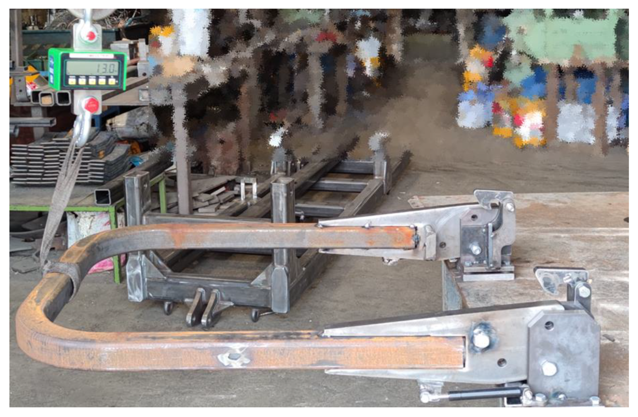
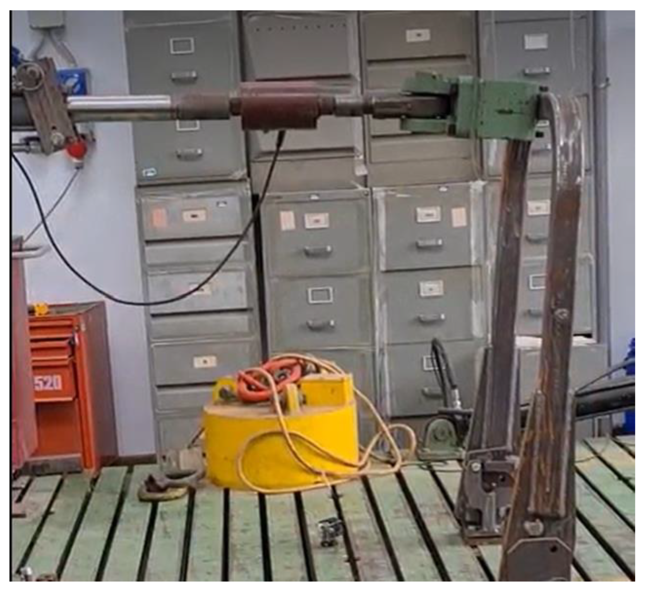
7.2. Physical Testing

Physical testing at the moment has been completed only for the validation of the ALD design, while the FAS system is still being analyzed.
In detail, a real prototype of the FROPS equipped with the locking system was realized and tested by means of the ROPS test rig set in the INAIL (the Italian Workers’ Compensation Authority) research center located in Monte Porzio Catone (Rome). The equipment installed in the laboratory can allow engineers to test the ROPS in accordance with the OECD Codes, thus ensuring the compliance of the system with current safety requirements. Due to privacy concerns, the description of the results achieved is simplified.
In Figure 13, the preliminary setting operations are shown, while in Figure 14, the test of the FROPS equipped with the ALD is shown, where a longitudinal force is applied at the top of the ROPS, pushing it from the front to the rear.
Indeed, this longitudinal force represents the most severe condition for the locking system, and the energy required by the OECD Code 7 [30] for a narrow-track wheeled tractor having a mass of 2000 kg was chosen as a benchmark. In practice, during the test, a maximum force of 20,480 N was reached, corresponding to the maximum deformation of the FROPS in the direction of the force, which was 223 mm (Figure 15).
The residual plastic deformation registered was about 96 mm. During the test that simulated the hit of the ground in case of a rollover, the locking system was able to maintain the FROPS in the upright locked configuration (safe configuration) and no significant deformations of the ALD were registered. After the removal of the force, both the locking systems (left and right) were still capable of locking the FROPS in the upright position as well as unlocking it for folding. Thus, the results achieved in terms of maximum deformation, plastic deformation, and maximum load (necessary for evaluating the energy absorbed by the structure) are in line with the results of tests developed on a similar FROPS with locking pins and mountings [36].

8. Discussion

Human interaction with mechanical systems represents a key factor in occupational safety in many sectors [37,38] and it is the cause of most severe injuries and fatalities occurring in agricultural activities [39]. Irwin and Poots [40] as well as Caffaro et al. [41], to cite a few, underlined the relevance of fatigue, time pressure, and stress as the main factors that can lead to the misuse of machinery among farmers Accordingly, a human-centered approach is needed to develop technical solutions aimed at facilitating working activities and reducing the risk of the misuse of work equipment such as tractors [42,43,44].
The current study represents a practical answer to these research hints through the development of a full assistance system (FAS) that can be applied to two-post FROPSs, which are usually equipped on narrow-track tractors. In addition, the FAS’s implementation was integrated with the development of a specific automatic locking device (ALD). The use of these combined systems can certainly reduce the risk of FROPS misuse since it eliminates manual handling by the operator. Moreover, the full assistance device also eliminates the risks of musculoskeletal diseases and those related to maneuvering the bar (whose weight is more than 70 kg in the analyzed case study), such as entanglement, cuts, and crashing.
The reliability of both the FAS and ALD has been verified by means of virtual modeling and testing: the output of these analyses demonstrated that the proposed approach can be suitable for retrofitting two-post FROPSs for narrow-track tractors. Indeed, considering the features of the components analyzed, the developed solutions can represent a useful reference for the implementation of FAS and ALD systems to a large variety of tractors already in use. Hence, these outcomes can be used to effectively increase the spread of retrofitted safety solutions for agricultural tractors, consistent with Kogler et al. [45], who stressed the need to augment information concerning safety solutions that can reduce the occupational risks of agricultural tractor users.
Compared to the development of similar technical solutions, such as the AutoROPS by Etherton et al. [24] or similar attempts [19,25], the FAS and ALD combined system presented in the current study presents the following advantages:
  • The system can be easily adapted to existing FROPS models, even if, in this case, an additional structural test is necessary to verify the compliance of the modified model of the protective structure with the OECD Codes;
  • The implementation costs are very low considering that the two electric actuators (one for each side of the FROPS) can be connected to the tractor’s battery for the energy supply;
  • Lowering/raising and locking operations can be carried out by the operator from the driving seat.
From the methodical point of view, the proposed approach is in line with the research findings of Casazza et al. [46], providing a detailed description of a reverse-engineering procedure that can be followed by researchers and practitioners to deal with the development of similar devices. Indeed, such an approach is effective when technical components have to be developed to upgrade existing machinery, consistent with Urbanic and El Maraghy [47]. Thus, FAS and ALD systems can be developed to equip both new tractor models and existing ones that should be retrofitted. These criteria can make the updating of tractors easier, facilitating compliance with OHS requirements [48].
Besides these positive results, the limitations of the study also need to be underlined. First, the application of the proposed approach requires a more extended validation concerning:
  • The physical tests of the FROPS equipped with the ALD to verify compliance with the OECD Codes;
  • The completion of the practical implementation of both systems on the tractor.
The integration of the FAS and ALD systems on the tractor is currently being analyzed to develop easy-to-use and safe leverage that should be installed in the tractor cockpit. This will allow us to better analyze the feasibility of the proposed solutions and their testing during working activities, i.e., when the tractor is used in in-field operations. Another criticality is related to the fact that the implementation of these systems has been verified for one type of tractor only, while further dimensioning to adapt them to other tractor models is needed.

9. Conclusions

Nowadays, agricultural machinery safety still represents a criticality both considering occupational contexts (i.e., the use of work equipment in agricultural companies) and private activities (i.e., the use of agricultural machinery by so-called hobbyists). For this reason, the inclusion of ergonomics analyses to improve the safety and usability of tractors can be beneficial in both contexts, contributing to increasing the social aspects of the sustainability of agricultural systems.
More specifically, the current study is an attempt to reduce the research gap on the misuse of FROPSs, which has been highlighted by numerous authors, improving the results of previous studies through the development of two novel technical solutions to augment the safety level of farmers.
Hence, the results achieved can augment knowledge on FROPS assistance systems for agricultural tractors on the one hand, while on the other providing a methodical approach that can be used to include the ergonomics and human factors analysis in the development of technical solutions to upgrade this type of machinery in accordance with current safety requirements.
However, further research is being carried out to fully validate the systems and complete the feasibility analysis both for the analyzed tractor model and for other types.

Author Contributions

Conceptualization, D.G., L.V., D.P. and M.F.; methodology, D.G., L.V., D.P. and M.F.; software, D.G. and L.V.; validation, D.G., L.V., D.P. and M.F.; writing—review and editing, D.G., L.V., D.P. and M.F. All authors have read and agreed to the published version of the manuscript.

Funding

This research received no external funding.

Data Availability Statement

Not applicable.

Conflicts of Interest

The authors declare no conflict of interest.

References

  1. Nawaz, W.; Linke, P.; Koҫ, M. Safety and sustainability nexus: A review and appraisal. J. Clean. Prod. 2019, 216, 74–87. [Google Scholar] [CrossRef]
  2. Fargnoli, M.; Lombardi, M. NOSACQ-50 for safety climate assessment in agricultural activities: A case study in Central Italy. Int. J. Environ. Res. Public Health 2020, 17, 9177. [Google Scholar] [CrossRef] [PubMed]
  3. Barneo-Alcántara, M.; Díaz-Pérez, M.; Gómez-Galán, M.; Carreño-Ortega, Á.; Callejón-Ferre, Á.J. Musculoskeletal disorders in agriculture: A review from Web of Science core collection. Agronomy 2021, 11, 2017. [Google Scholar] [CrossRef]
  4. International Labour Office (ILO). Safety and Health at Work, A Vision for Sustainable Prevention. Available online: https://www.ilo.org/wcmsp5/groups/public/@ed_protect/@protrav/@safework/documents/publication/wcms_301214.pdf (accessed on 19 November 2022).
  5. Facchinetti, D.; Santoro, S.; Galli, L.E.; Pessina, D. Agricultural tractor roll-over related fatalities in Italy: Results from a 12 years Analysis. Sustainability 2021, 13, 4536. [Google Scholar] [CrossRef]
  6. Pochi, D.; Fornaciari, L.; Vassalini, G.; Grilli, R.; Fanigliulo, R. Levels of whole-body vibrations transmitted to the driver of a tractor equipped with self-levelling cab during soil primary tillage. AgriEngineering 2022, 4, 695–706. [Google Scholar] [CrossRef]
  7. Vita, L.; Gattamelata, D.; Pessina, D. Retrofitting agricultural self-propelled machines with roll-over and tip-over protective structures. Safety 2021, 7, 46. [Google Scholar] [CrossRef]
  8. Pinzke, S.; Svennefelt, C.A.; Lundqvist, P. Occupational injuries in Swedish agriculture–development and preventive actions. J. Agric. Saf. Health 2018, 24, 193–211. [Google Scholar] [CrossRef]
  9. Myers, J.R.; Hendricks, K.J. Agricultural tractor overturn deaths: Assessment of trends and risk factors. Am. J. Ind. Med. 2010, 53, 662–672. [Google Scholar] [CrossRef]
  10. Fargnoli, M.; Lombardi, M. Safety vision of agricultural tractors: An engineering perspective based on recent studies (2009–2019). Safety 2020, 6, 1. [Google Scholar] [CrossRef] [Green Version]
  11. Sorensen, J.A.; Jenkins, P.; Bayes, B.; Clark, S.; May, J.J. Cost-effectiveness of a ROPS social marketing campaign. J. Agric. Saf. Health 2010, 16, 31–40. [Google Scholar] [CrossRef]
  12. Hard, D.L.; McKenzie, E.A.; Cantis, D.; May, J.; Sorensen, J.; Bayes, B.; Madden, E.; Stone, B.; Maass, J. The NIOSH CROPS demonstration project: A study in New York and Virginia with an emphasis on youth. J. Agric. Saf. Health 2016, 22, 173–186. [Google Scholar] [CrossRef] [Green Version]
  13. Cavallo, E.; Langle, T.; Bueno, D.; Tsukamoto, S.; Görücü, S.; Murphy, D. Rollover protective structure (ROPS) retrofitting on agricultural tractors: Goals and approaches in different countries. J. Agromed. 2014, 19, 208–209. [Google Scholar] [CrossRef]
  14. European Agency for Safety and Health at Work (EU-OSHA). Maintenance in Agriculture—A Safety and Health Guide; Publications Office of the European Union: Luxembourg, 2011; Available online: https://data.europa.eu/doi/10.2802/54188 (accessed on 19 November 2022).
  15. Gattamelata, D.; Puri, D.; Vita, L.; Fargnoli, M.; Lombardi, M. Retrofitting agricultural tractors with aftermarket weather cabins: Safety issues for manufacturers and users. In Proceedings of the International Conference on Industrial Engineering and Operations Management (IEOM), Rome, Italy, 2–5 August 2021; pp. 339–350. Available online: http://ieomsociety.org/proceedings/2021rome/306.pdf (accessed on 19 November 2022).
  16. Mann, A.J.; Jepsen, S.D. Using expert panel data to guide youth agricultural safety and health training resources in the US. Safety 2017, 3, 4. [Google Scholar] [CrossRef] [Green Version]
  17. Silleli, H.; Dayıoglu, M.A.; Gültekin, A.; Saranlı, G.; Yıldız, M.A.; Akay, E.; Ekmekçi, K. Anchor mechanism to increase the operator clearance zone on narrow-track wheeled agricultural tractors: Static and field upset test results. Biosyst. Eng. 2008, 99, 196–204. [Google Scholar] [CrossRef]
  18. Ballesteros, T.; Arana, I.; Ezcurdia, A.P.; Alfaro, J.R. E2D-ROPS: Development and tests of an automatically deployable, in height and width, front-mounted ROPS for narrow-track tractors. Biosyst. Eng. 2013, 116, 1–14. [Google Scholar] [CrossRef]
  19. Ballesteros, T.; Arana, J.I.; De Ezcurdia, A.P.; Alfaro, J.R. Development and validation of automatically deployable ROPS based on airbag inflator technology. Biosyst. Eng. 2015, 130, 92–105. [Google Scholar] [CrossRef]
  20. Cremasco, M.M.; Caffaro, F.; Giustetto, A.; Vigoroso, L.; Paletto, G.; Cavallo, E. Tractor rollover protection: Is the incorrect use of foldable rollover protective structures due to human or to technical issues? Hum. Factors J. Hum. Factors Ergon. Soc. 2020, 62, 64–76. [Google Scholar] [CrossRef]
  21. Vigoroso, L.; Caffaro, F.; Micheletti Cremasco, M.; Cavallo, E. Improving tractor safety: A comparison between the usability of a conventional and enhanced rear-mounted foldable ROPS (FROPS). Int. J. Environ. Res. Public Health 2022, 19, 10195. [Google Scholar] [CrossRef]
  22. Molari, G.; Rondelli, V. On the definition of narrow-track wheeled agricultural tractors. Biosyst. Eng. 2004, 88, 75–80. [Google Scholar] [CrossRef]
  23. Micheletti Cremasco, M.; Vigoroso, L.; Caffaro, F.; Paletto, G.; Cavallo, E. Considering human variability in the design of safe interaction with agricultural machinery: The case of foldable roll-over protective structure (FROPS) manual handling. Agronomy 2021, 11, 1303. [Google Scholar] [CrossRef]
  24. Etherton, J.; McKenzie, J.E.A.; Lutz, T.; Cantis, D.; Kau, T.Y. An initial farmer evaluation of a NIOSH AutoROPS prototype. Int. J. Ind. Ergon. 2004, 34, 155–165. [Google Scholar] [CrossRef]
  25. Alkhaledi, K.; Means, K.; McKenzie, J.E.; Smith, J. Reducing occupational fatalities by using NIOSH 3rd generation automat-ically deployable rollover protective structure. Saf. Sci. 2013, 51, 427–431. [Google Scholar] [CrossRef]
  26. Pessina, D.; Facchinetti, D. A survey on fatal accidents for overturning of agricultural tractors in Italy. Chem. Eng. Trans. 2017, 58, 79–84. [Google Scholar] [CrossRef]
  27. Gattamelata, D.; Vita, L.; Fargnoli, M. Machinery safety and ergonomics: A case study research to augment agricultural tracklaying tractors’ safety and usability. Int. J. Environ. Res. Public Health 2021, 18, 8643. [Google Scholar] [CrossRef] [PubMed]
  28. Fargnoli, M.; Vita, L.; Gattamelata, D.; Laurendi, V.; Tronci, M. A reverse engineering approach to enhance machinery design for safety. In Proceedings of the DESIGN 2012, the 12th International Design Conference, Dubrovnik, Croatia, 21–24 May 2012; Marjanovic, D., Storga, M., Pavkovic, N., Bojcetic, N., Eds.; International Design Conference: Dubrovnik, Croatia, 2012; pp. 627–636, ISBN 978-953-7738-17-4. [Google Scholar]
  29. Wood, K.L.; Jensen, D.; Bezdek, J.; Otto, K.N. Reverse engineering and redesign: Courses to incrementally and systematically teach design. J. Eng. Educ. 2001, 90, 363–374. [Google Scholar] [CrossRef]
  30. Organisation for the Economic Co-Operation and Development (OECD). Tractors standard Codes 4, 6, 7, 8. Organisation for the Economic Co-Operation and Development Paris, France. Available online: https://www.oecd.org/agriculture/tractors/codes/ (accessed on 19 November 2022).
  31. Pessina, D.; Facchinetti, D.; Giordano, D.M. Narrow-track agricultural tractors: A survey on the load of the hand-operated foldable rollbar. J. Agric. Saf. Health 2016, 22, 275–284. [Google Scholar] [CrossRef] [Green Version]
  32. Franceschetti, B.; Rondelli, V. Models to predict the force to operate front foldable rollover protective structures for narrow-track tractors. Biosys. Eng. 2019, 185, 126–134. [Google Scholar] [CrossRef]
  33. Vigoroso, L.; Caffaro, F.; Cremasco, M.M.; Giustetto, A.; Paletto, G.; Cavallo, E. A bottom-up approach to tractor safety: Improving the handling of foldable roll-over protective structures (FROPS) through user-centred design. In Innovative Bio-Systems Engineering for Sustainable Agriculture, Forestry and Food Production, Lecture Notes in Civil Engineering 67, Proceedings of the International Mid-Term Conference of the Italian Association of Agricultural Engineering, Matera, Italy, 12–13 September 2019; Coppola, A., Di Renzo, G., Altieri, G., D’Antonio, P., Eds.; Springer Nature: Geneve, Switzerland, 2020; pp. 645–652. [Google Scholar] [CrossRef]
  34. Vigoroso, L.; Caffaro, F.; Cavallo, E.; Cremasco, M.M. User-centred design to promote the effective use of rear-mounted foldable roll-over protective structures (FROPSs): Prototype evaluation among novice and expert farmers. Span. J. Agric. Res. 2021, 19, e0207. [Google Scholar] [CrossRef]
  35. MSC Adams Software. Available online: https://hexagon.com/it/products/product-groups/computer-aided-engineering-software/adams (accessed on 19 November 2022).
  36. Italian Workers’ Compensation Authority (INAIL). L’installazione dei Dispositivi di Protezione in Caso di Ribaltamento nei Trattori Agricoli o Forestali. Linee Guida: (Installation of Protection Devices in the Event of Overturning of Agricultural or Forestry Tractors. Guidelines). Available online: https://www.inail.it/cs/internet/comunicazione/pubblicazioni/catalogo-generale/linstallazione-dei-dispositivi-di-protezione.html (accessed on 19 November 2022).
  37. Fargnoli, M. Design for safety and human factors in industrial engineering: A review towards a unified framework. In Proceedings of the 11th Annual International Conference on Industrial Engineering and Operations Management, Singapore, 7–11 March 2021; pp. 7511–7522. [Google Scholar]
  38. Urquhart, L.; Wodehouse, A.; Loudon, B.; Fingland, C. The application of generative algorithms in human-centered product development. Appl. Sci. 2022, 12, 3682. [Google Scholar] [CrossRef]
  39. Kim, H.; Lee, K.; Räsänen, K. Agricultural injuries in Korea and errors in systems of safety. Ann. Agric. Environ. Med. 2016, 23, 432–436. [Google Scholar] [CrossRef]
  40. Irwin, A.; Poots, J. Investigation of UK farmer go/no-go decisions in response to tractor-based risk scenarios. J. Agromed. 2018, 23, 154–165. [Google Scholar] [CrossRef]
  41. Caffaro, F.; Cremasco, M.M.; Roccato, M.; Cavallo, E. Drivers of farmers’ intention to adopt technological innovations in Italy: The role of information sources, perceived usefulness, and perceived ease of use. J. R. Stud. 2020, 76, 264–271. [Google Scholar] [CrossRef]
  42. Fargnoli, M.; Lombardi, M.; Haber, N. A fuzzy-QFD approach for the enhancement of work equipment safety: A case study in the agriculture sector. Int. J. Reliab. Saf. 2018, 12, 306–326. [Google Scholar] [CrossRef]
  43. Sadeghi, L.; Dantan, J.Y.; Mathieu, L.; Siadat, A.; Aghelinejad, M.M. A design approach for safety based on product-service systems and function–behavior–structure. CIRP J. Manuf. Sci. Technol. 2017, 9, 44–56. [Google Scholar] [CrossRef] [Green Version]
  44. Keskin, S.G.; Keskin, M.; Soysal, Y. Assessing farm tractor incidents and awareness levels of operators for tractor safety issues in the Hatay province of Turkey. J. Agric. Saf. Health 2012, 18, 113–128. [Google Scholar] [CrossRef]
  45. Kogler, R.; Quendler, E.; Boxberger, J. Occupational accidents with agricultural machinery in Austria. J. Agromed. 2016, 21, 61–70. [Google Scholar] [CrossRef]
  46. Casazza, C.; Martelli, R.; Rondelli, V. Evaluation of a commercial tractor safety monitoring system using a reverse engineering procedure. J. Agric. Saf. Health 2016, 22, 215–225. [Google Scholar] [CrossRef] [Green Version]
  47. Urbanic, R.J.; ElMaraghy, W. A design recovery framework for mechanical components. J. Eng. Des. 2009, 20, 195–215. [Google Scholar] [CrossRef]
  48. Tinc, P.J.; Gadomski, A.; Sorensen, J.A.; Weinehall, L.; Jenkins, P.; Lindvall, K. Applying the consolidated framework for implementation research to agricultural safety and health: Barriers, facilitators, and evaluation opportunities. Saf. Sci. 2018, 107, 99–108. [Google Scholar] [CrossRef]
Figure 1. Examples of a rear-mounted FROPS (left) and a front-mounted FROPS (right).
Agriengineering 05 00015 g001
Figure 2. Scheme of the proposed research approach.
Agriengineering 05 00015 g002
Figure 3. Accessible zones of the grasping area for a wheeled tractor according to OECD Code 6 criteria.
Agriengineering 05 00015 g003
Figure 4. Scheme of the analyzed tractor (α represents the folding angle of the FROPS).
Agriengineering 05 00015 g004
Figure 5. Model of the geometrical features of the linear actuator (AF and AM represent the anchorage points of the actuator).
Agriengineering 05 00015 g005
Figure 6. Procedure to define the AF and AM points: (a) determination of the angular range of motion ∆α and AM; (b) determination of the AM point in the rest configuration (A’M); (c) determination of the fixed anchorage point of the linear actuator (AF).
Agriengineering 05 00015 g006
Figure 7. Operating phases of the locking device.
Agriengineering 05 00015 g007
Figure 8. Scheme of the engagement and locking configuration.
Agriengineering 05 00015 g008
Figure 9. Dynamic simulation of the system (raising time 2.5 s and constant speed of the actuator).
Agriengineering 05 00015 g009
Figure 10. Three-dimensional model of the system used for the dynamic simulation.
Agriengineering 05 00015 g010
Figure 11. Comparison of the FAS raising force when adopting three raising times (1 s, 2.5 s, and 5 s).
Agriengineering 05 00015 g011
Figure 12. Von Mises stress diagram of the longitudinal load (energy value 4500 Joules).
Agriengineering 05 00015 g012
Figure 13. Preliminary setting operations.
Agriengineering 05 00015 g013
Figure 14. Application of a longitudinal force to test the behavior of the ALD.
Agriengineering 05 00015 g014
Figure 15. The plot of the plastic deformation.
Agriengineering 05 00015 g015
Disclaimer/Publisher’s Note: The statements, opinions and data contained in all publications are solely those of the individual author(s) and contributor(s) and not of MDPI and/or the editor(s). MDPI and/or the editor(s) disclaim responsibility for any injury to people or property resulting from any ideas, methods, instructions or products referred to in the content.

