Article

Performance Evaluation of Balcony Designs for Mitigating Ground Level Noise

Institute of High Performance Computing (IHPC), Agency for Science, Technology and Research (A*STAR), 1 Fusionopolis Way, #16-16 Connexis, Singapore 138632, Singapore
*
Authors to whom correspondence should be addressed.
Acoustics 2024, 6(1), 272-297; https://doi.org/10.3390/acoustics6010015
Submission received: 24 December 2023 / Revised: 16 February 2024 / Accepted: 27 February 2024 / Published: 11 March 2024

Abstract

:
This study aims to tackle the challenge of high noise levels on balconies while preserving natural ventilation. Eight innovative balcony designs, incorporating elements like diffuser edges, undulating ceilings, Helmholtz resonators, grooves, or sound traps, were evaluated via finite element (FE) modeling. The insertion loss results showed that for many balcony designs, noise reduction in the balcony could deteriorate beyond an elevation of 8 m. However, the front jagged and full wavy ceiling designs were shown to be more robust in noise attenuation across balconies on different floors. The jagged ledge and grooved parapet designs yielded an overall 1.5 dBA lower SPL at the exterior regions, compared to other designs, which implies that the designs are less acoustically detrimental to nearby residential blocks as they tend to diffract and absorb incident noise. The jagged ledge design is more effective for lower floors while the jagged ceiling design is more effective for higher floors. A combination of the protruded jagged ledge for the lower floor and jagged balcony ceiling for the higher floor would result in the lowest noise ingress over three stories of residential units: this would be capable of achieving more than 3 dB noise reduction and would offer viable options for improving balcony noise mitigation, by providing valuable insights to architects and designers seeking practical solutions for outdoor noise reduction. Our study highlights that whereas the spectrum characteristics of acoustic absorption materials may be less tunable, and where reduced head space is traded for thicker material for greater ab-sorption and added affixation and maintenance cost, the jagged ledge and ceiling curvatures can actually be shape-tuned, say for every 3 to 4 floors up the high-rise to more effective reduce noise ingress and possibly improve the architecture façade outlook.

1. Introduction

1.1. Background

In residential buildings, opting for a balcony instead of traditional windows offers various advantages, including the provision of panoramic views, space for planting, and improved natural ventilation. The benefits extend beyond mitigating internal noise levels in adjacent rooms, as the open balcony brings additional benefits such as enhancing thermal comfort and indoor air quality. An upper-floor balcony serves the dual purpose of offering solar shading and reducing the electricity consumption of air conditioning in the underlying flat, contributing to sustainable, green building design [1]. In recognising balconies as a green feature, the Building and Construction Authority (BCA) of Singapore incorporated them into its Green Mark Scheme [2]. The BCA incentivizes developers and architects by offering up to 2% additional gross floor area beyond the master plan gross plot ratio for incorporating such features. Hong Kong similarly recognizes noise attenuating balconies as green features in residential buildings [3]. These considerations highlight the multifaceted advantages and environmental sustainability associated with incorporating balconies into residential building designs.
Balcony acoustic treatments typically involve constructing solid parapets and ensuring the balcony ceiling has acoustic absorption [1]. Li et al. [4] conducted a study of open-type (cantilever) and close-type (featuring a parapet at the front or sides) balconies exposed to traffic noise from parallel and perpendicular roads. The results indicated that on lower floors, the broader viewing angle allowed sound rays to penetrate and undergo reflections, leading to poorer insertion loss (IL). Conversely, on higher floors, receivers situated deeper in the shadow zone exhibited better IL due to a limited viewing angle. Li et al. [4] also observed a decrease in IL values with an increase in receiver height from the balcony floor, which is intuitively explained by lower points being within the balcony’s shadow zone and higher points being closer to or within the illumination zone. Additionally, they found that side walls might amplify noise through reverberation, particularly when the road is parallel to the balconies and traffic noise intrudes through the front opening. The efficacy of parapets or side walls against road traffic noise hinges on their orientations to the affecting roads, and factors such as reflecting surfaces and diffraction of sound waves at parapet edges contribute to the overall balcony performance.

1.2. Literature Review

Lee et al. [5] conducted a comprehensive study of various balcony treatments, including parapets, lintels, absorbers, and different balcony ceiling angles, to assess their efficacy in reducing exterior noise for a group of buildings. Utilizing computer simulations and scale model tests, they found that parapets were more effective than lintels, and also observed taller parapets demonstrated greater noise reduction by limiting the viewing angle of incident and reflected sounds. Inclined ceilings did not yield positive noise reduction in lower building stories but reached a maximum reduction of 9.4 dB on the 11th floor, which was attributed to varying incident angles from the sound source. As reported by various studies [4,5,6,7,8,9,10], acoustic treatment of wall surfaces could reduce road traffic noise by approximately 10–15 dBA, depending on balcony geometry, street geometry, and noise sources. The design incorporating absorbing materials on both the ceiling and inner side of the parapet demonstrated the highest noise reduction. Sound pressure level (SPL) measurements of balconies revealed that noise from nearby areas, such as a parking lot and outdoor market, could propagate to upper floors without significant reduction, resulting in slightly higher noise levels on upper floors. This observation is consistent with the findings reported by others [9,11], whereby rigid walls parallel to each other on either side of the road could give rise to multiple reflections between them, resulting in significantly poorer performance. Lee et al. [5] observed noise reduction with increasing floor levels in isolated buildings but noted decreased acoustic performance in an apartment complex due to increased sound reflection and long reverberation time.
El Dien and Woloszyn [12] conducted an investigation into the acoustic characteristics of balconies with three different ceiling inclined angles (5°, 10°, and 15°) using computer simulations, and found the orientation of the balcony ceiling influenced noise ingress by redirecting reflected rays away from the dwelling. Interestingly, the impact of an inclined ceiling was not discernible below the fourth floor, where the dominant direct noise component prevailed. Contrary to expectations, larger balcony depths led to noise amplification with an inclined ceiling, which was attributed to an increase in reflective surfaces. Effective noise attenuation was observed beyond the fifth floor, both in terms of height and balcony depth, as the inclined parapet expanded the shadow zone of the building facade.
Yeung [13] proposed alternative noise mitigation strategies for specially designed balconies, presenting viable options when conventional measures like solid parapet walls are impractical. One such design featured balconies equipped with full-height top-hung windows, limiting the opening angle to 10°, and tempered glass barriers at the lower part of the window opening to mitigate rail traffic noise. The attenuation effect was enhanced through the incorporation of a micro-perforated membrane on the acoustic box (with absorbent on all sides) and the windowsill, which was situated atop the tempered glass barrier with absorbent material underneath. In-situ measurements demonstrated a substantial noise level difference of approximately 17 dBA between the interior and exterior of balconies with the top-hung window open. These specially designed balconies proved effective in addressing noise challenges at the sites and facilitated adequate natural ventilation.
Hammad et al. [14] utilized a scale model to assess the attenuation within an adjacent room, both before and after installing different balcony types. Their findings revealed that the efficacy of a solid parapet diminishes at higher floor levels and on deeper balconies, due to a reduction in the additional path difference introduced by the solid parapet. Introducing semi-permeable screens above parapets was found to increase the shielded area of reflective surfaces within the balcony, thereby improving noise attenuation. Kropp and Bérillon [15] validated their three-dimensional theoretical model through scale model tests, finding that ceiling absorption has a more pronounced effect when the balcony is elevated significantly against the source position but is less effective when the source and balcony are at similar elevations.
Tang’s [7] investigation into various balcony types, conducted with a 1:10 scale model, revealed that closed balconies exhibited the highest IL, while bottom-type balconies showed the lowest. The variation of the elevation angle between the source and the balcony was found to be correlated with the IL by a second-order polynomial equation. The study emphasized that the screening performance of balconies was primarily influenced by the front panel, a factor of increasing significance, particularly for distant noise sources. In the presence of a ceiling, amplification was observed at heights 2 m above the balcony floor. In contrast, when no ceiling was present, positive IL values were mostly noted for all heights above the balcony floor and across all balcony types. The higher attenuation observed for closed and front–bottom balconies suggested that parapets contribute more to diffraction attenuation than to reverberation amplification. Interestingly, with a ceiling, the type of balcony did not seem to significantly impact IL on a frequency basis. As the distance between the noise source and receiver increased, Tang [7] also reported an increase in IL in mid to high frequencies. Additionally, the study found that treating balcony floors did not provide significant acoustic protection, especially for distant noise sources. Instead, the influence of ceiling reflection became more crucial when the building was in proximity to the noise source. Tang [7] highlighted that ceiling reflection resulted in sound amplification at nearly all height levels of balconies.
Ho et al. [16] presented innovative strategies for mitigating road traffic noise. One design involved fixed windows placed in protruded rooms facing significant traffic noise sources, while openable side windows faced quieter fronts. Another approach featured a modified double-glazed window with offset openings to facilitate natural ventilation. Additionally, an acoustic balcony design was developed, incorporating a front parapet inclined upward by approximately 25°. To address noise concerns, a sliding screen was installed in front of the balcony door, offering effective noise reduction of about 2 to 6 dBA, as confirmed by resident surveys conducted after the building was being occupied. The tenants expressed satisfaction with the noise reduction achieved by this design.
Naish et al. [17] investigated the spatial distribution of noise levels on balconies constructed with solid parapets, side walls, ceiling shields, and absorptive material, with a focus on assessing the impact of road traffic noise on speech interference. The acoustic absorption on ceilings and walls involved corrugated sheet metal perforated with holes, offset from the outer surface to create a 25 mm cavity filled with absorptive material such as fiberglass. In a related study, Hothersall et al. [9] employed two-dimensional boundary element models to examine the sound field around balconies in a tall building near a roadway. Their findings indicated that treating the ceiling or the rear balcony wall was the most effective in reducing traffic noise levels by 4 to 7 dBA. The balconies considered in both studies had dimensions 0.9 m in depth, 2.9 m in height, and a balcony wall height of 0.1 m, mirroring the models used in the current study. Hothersall et al. [9] suggested that impinging noise resulted from scattering due to the non-planar building façade and the effects of sound interference and standing waves within the balcony caused by reflections from parapet walls. The oscillations in the IL spectra were attributed to the interference of waves reflected from internal balcony surfaces. The study noted diminishing returns in increasing the absorption-treated area. While Hothersall et al. [9] considered surface treatments, we chose to explore the use of both sound traps and Helmholtz resonators, leveraging available space at the ceiling.
In a laboratory study, Chiu et al. [18] showed that balconies featuring ceilings and side walls with sound absorption materials covering all internal surfaces could achieve a traffic noise IL of approximately 6 dBA, compared to traditional open windows. Lars et al. [19] investigated the effectiveness of double-layered windows with an intervening air gap, incorporating sound-absorbing slits or perforated plates along window edges to facilitate ventilation. These designs exhibited favorable acoustic properties, leveraging a large vertical channel that the noise must traverse before reaching the inner part’s outlet. To enhance sound insulation in the lower frequency range, the researchers further improved the design by incorporating sound absorbers based on Helmholtz resonators and perforated plates within the cavity. For the resonator-based approach, a small cavity was constructed within the external cavity wall, filled with mineral wool, and fitted with Helmholtz resonators facing the cavity between the windows. The external cavity wall was then sealed with gypsum plates, featuring holes in the resonator positions. In the perforated plate design, a small cavity was built around the window edges at the top, bottom, and sides. By involving the construction of an external sound trap or plywood box attached to the external surface of the façade, the setup allowed for noise absorption while enabling ventilation.
El Dien and Woloszyn [20] emphasized that the traditional approach to enhancing the sound insulation of building facades involves treatments such as installing sealed double glazing or incorporating absorbing materials. An alternative strategy is to design self-protecting buildings where weak points on facades are shielded from direct external noise. Acoustic protection at lower levels, and across all balcony depths, was identified as suboptimal due to the strong influence of direct and reflected noise components. The study explored the inclination of balcony ceilings as a method to reduce the power of reflection and diffuse energy components. Results indicated that inclined angles exceeding 5° were more effective at lower levels, while an inclined angle of 5° was more effective at higher levels. Experiments by Tong et al. [21] concluded that the balcony ceiling was the most suitable location for installing artificial sound absorption to enhance broadband IL, a finding consistent with Hothersall et al. [9]. The maximum broadband road traffic noise IL was approximately 7 dB. Tong et al. [21] and El Dien and Woloszyn [20] highlighted that the up-and-down fluctuations in IL observed in their plots were a result of resonant modes caused by reflections and barrier effect, which varied with frequency. It was observed that the number of longitudinal modes between the balcony and window openings increased with higher frequency, leading to a reduction in balcony IL. The results suggested that sound absorption treatment of the balcony ceiling was the most effective, followed by absorption of the rear or side walls. Additional sound absorption beyond treating the ceiling and side walls yielded negligible improvement of broadband IL, reaching a maximum amount of about 7 dB.
In a separate experimental study, El Dien and Woloszyn [10] suggested that increasing balcony depth and inclining the parapet could effectively diminish reflected and diffuse energy components, thereby enhancing the shielding zone, compared to the conventional parapet design. Two parapet incline angles, 15° and 30° to the vertical, were tested. The results indicated that, for a balcony depth of 1 m, the parapet inclined at 15° was more effective at higher floors. However, for deeper balconies of 2 m and 3 m, the parapet inclined at 30° exhibited greater reduction and proved more effective for higher floors. They observed that projection depths led to average reductions ranging from 4 to 8 dBA, while inclined parapets provided additional reduction values of 0.5 to 4 dBA. Notably, higher points in the structure exhibited greater improvements in protection, which was attributed to the increased shadow zone resulting from the inclined parapet.
The exploration of active noise control to mitigate sound diffraction at balcony edges has been a focus of research [22]. Wang et al. [23] presented a balcony design with a ceiling made from materials of inhomogeneous impedance. This approach manipulated the behavior of reflected waves, altering the angle of reflection on the ceiling to guide sound energy away from the balcony dwelling rather than reflecting deeper into the balcony space. The balcony ceiling in their design featured a closely spaced array of progressively tuned hollow tubes, creating a phase gradient with varying specific impedance. The calculated IL of this treatment ranged from 6 to 15 dB, with the maximum IL observed at 4000 Hz. This concept aligns with our work, in which both front jagged and full wavy ceiling designs aim to modify absorption and reflection characteristics to achieve a reduction of noise ingress. However, the design proposed by Wang et al. [23] is more intricate and poses challenges for maintenance and cleaning, due to the numerous sharp edges in the small channels. Additionally, it may not be regarded as aesthetically pleasing when compared to our proposed designs. Wang et al. [23] reported that with optimal design considerations for tube separation and length periodization, the performance of a balcony with closely spaced tubes in the low- and mid-frequency bands can be further improved.

1.3. Motivation

Noise pollution regulations in Singapore establish that the maximum permissible vehicle noise for the motorcycle and motorcar is 94 and 96 dBA, respectively. The recommended noise level within the residential unit so quality of life and rest at night-time are not affected is 60 dBA. In the literature review presented above, it is obvious that typical balconies cannot provide adequate acoustical protection in the presence of ceiling reflections, since the ingress SPL are reported to be above 60 dBA. Windows on the balconies would usually have to be shut to fully prevent noise ingress or significant sound absorption treatment of the balcony surfaces would have to be incorporated. Whereas most studies reported using conventional absorption material, such as fiber glass boards or foams, we instead focused on the physical form of the ceiling and parapet walls to investigate the as–is effect of such balcony design, since the former may not be durable for long term use due to exposure to the weather, and hence is likely to incur more maintenance costs. Furthermore, there are already many absorption materials on the market. Running models with different absorption values, compared to modifying the structural shape of the balcony to improve noise attenuation performance, do not provide further academic insight. Our work can be viewed as an extension of the work by Wang et al. [23], which explored various designs that modify the response of localized balcony regions.

2. Materials and Methods

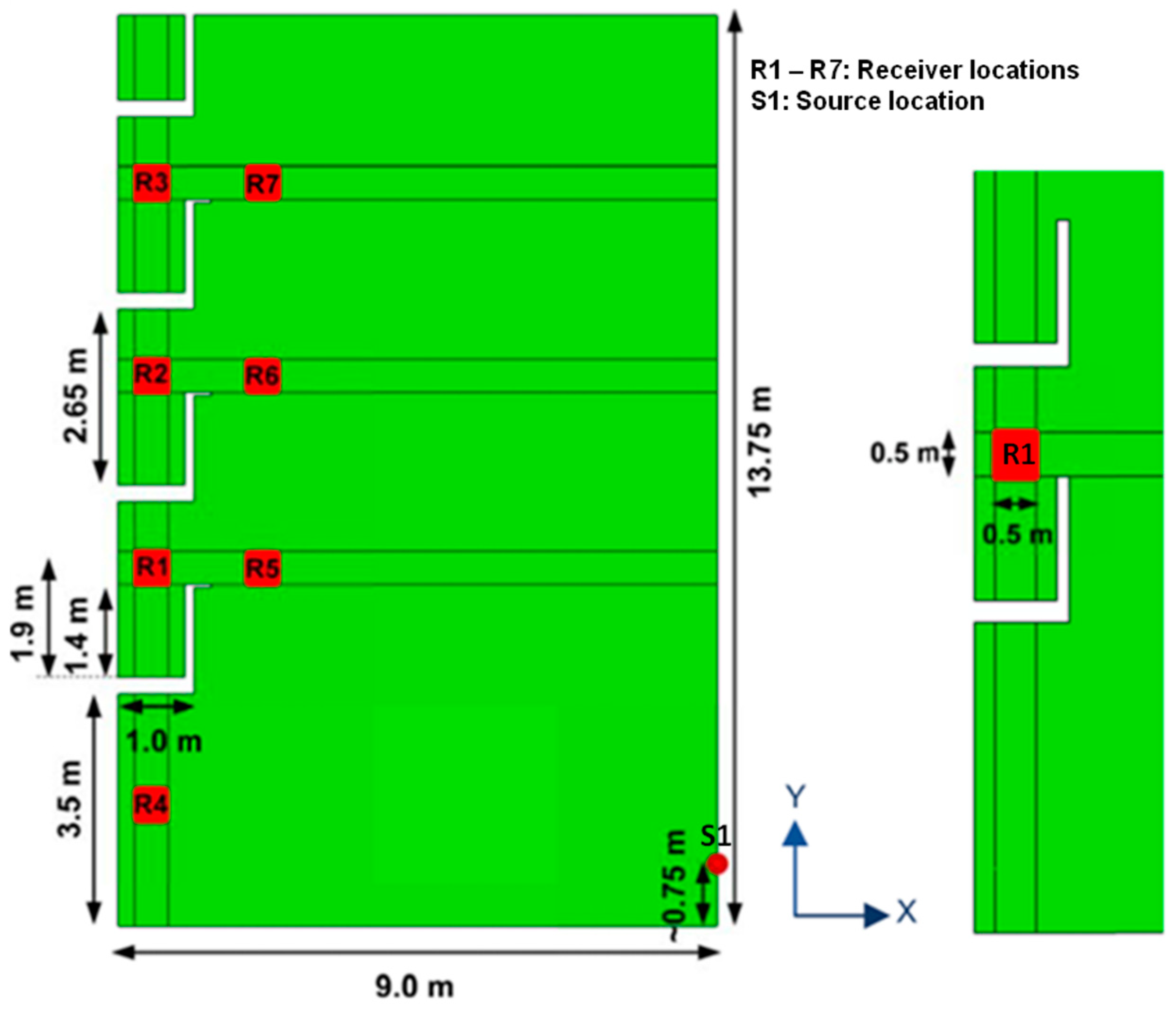
2.1. Finite Element Model

The main objective of this work was to investigate the effect of different balcony designs on the mitigation of ground noise. The investigated range of frequency was from 200 Hz to 2000 Hz because our previous studies revealed that the source frequencies for both traffic and construction noises are typically between 500 Hz and 1200 Hz. The steady-state dynamics (direct analysis) procedure in Abaqus/Standard v2016 was used to perform the frequency sweep analysis at a linear interval of 100 Hz. The frequency sweep analysis is an approach that runs the simulation for every 100 Hz (interval) from 500 Hz to 1200 Hz as the frequency of the sound waves emitting from the noise source. This resulted in a total of 19 data points for each element of the model. The air domain was created by immersing the air block within the geometries of balcony floors, ceilings, and parapet walls. In the Assembly module, the merge/cut function was employed to generate the final air domain by removing air regions occupied by the balcony. Eight different balcony designs were examined—see Figure 1, which provides an overall view of the balcony models. The details of the balcony features will be discussed later. 3D acoustic analysis was performed on sliced models, which were used to incorporate a thickness component, to facilitate the study of non-axisymmetric designs of parapet ledges. The primary focus was on front parapet and ceiling designs, aligning with findings from the literature that suggest these features—specifically, front parapet screening and diffraction effects, and ceiling reflection—have the most significant impact on balcony noise. In contrast, side walls, consistently reported to have a lesser effect on balcony noise, were not investigated in this study.
The acoustic modeling space for FE analysis measured 9 m by 13.75 m, with a thickness of 0.767 m (see Figure 2). This floor elevation is almost five stories with four balconies and is similar to the measurement space reported by Li et al. [4] and May [6]. It was observed that for high-story balconies, there is typically minimal ground noise diffraction at the parapet or ceiling reflection [7]. Consequently, beyond a certain elevation, such as the seventh floor, traffic noise from the ground is unlikely to reach within the balcony, especially when the noise source is close to the building. This is due to the absence of a direct line-of-sight from the balcony ledge or ceiling to the sound source, along with natural noise attenuation over the significant distance. The modeled balcony had a depth of 1 m, a 25 cm thick balcony floor slab, and a floor-to-ceiling height of 2.65 m. The front parapet wall was 1.4 m tall and 15 cm thick. The acoustic properties of air at 25 °C were utilized in the analyses (Table 1).
In all models, the surfaces of the balconies were assumed to be smooth and rigid. Consequently, these surfaces within the air domain were assigned a sound hard reflecting boundary condition. Since we were simulating an exterior problem, the two large surfaces on the X–Y plane and the top edge of the models were given radiative boundary conditions. Additionally, acoustic infinite elements were utilized to enable the dissipation of sound energy from these surfaces, creating a simulation of an external environment. In our study, there was no assumption of a rear wall for the balcony. Instead, a full-wall window providing access to the balcony was considered to be completely open. This setup allowed us to evaluate the worst-case scenario, in which noise could propagate into the adjacent room. Therefore, the left edges of the air domain within the balcony were also subjected to the aforementioned boundary conditions.
A spherical noise source, S1, generating 1 Pa (equivalent to 94 dB SPL) was positioned at a node on the left edge of the models, as illustrated in Figure 2. This is similar to the sound pressure level of 93.5 dBA measured by Lee et al. [5] using a single spark source. The source was horizontally situated 7.85 m away from the exterior surface of the parapets, at a height of 0.73 m from the ground. In the frequency sweep analysis, the 1 Pa sound source remained constant across all analyzed frequency steps. The specific value of the sound source is not crucial since the assessment of designs relied on comparing sound levels within the balcony. It is essential that all boundary and source conditions remained consistent across all models. The right edge was assigned a sound hard reflecting boundary condition, while the ground was subjected to impedance values referenced from absorption coefficients reported for porous asphalt road and ground [24,25,26]. The equation for converting an absorption coefficient to the corresponding acoustic impedance for a specific frequency is given by
Z f = Z 0 1 + 1 α f 1 1 α f
where the subscript f (Hz) denotes the frequency, α f denotes the frequency-dependent absorption coefficient, Z 0 denotes the acoustic impedance for air (Ns/m3), and Z 0 denotes the frequency-dependent acoustic impedance of the material (Ns/m3).
It is well-established [27] that there should be at least six linear elements spanning across the shortest wavelength of interest (i.e., highest frequency of interest). At 2 kHz, the corresponding wavelength is 0.17 m for the speed of sound given in Table 1. This led to an element size of around 2.45 cm. A mesh sensitivity check was made by the Mesh module to ensure that the analyses would be accurate for up to 2 kHz. In total, the different models were made up of 7.7–11.6 millions of elements. This large-scale FE problem requires the use of a high-performance workstation with 256 GB of memory and 12 processors, each running at 3.2 GHz. Abaqus/Standard v2016 was used to solve the acoustic problem and each balcony case typically requires 48 h of computational time. We could only consider the human vocal range caused by grassroot activities up to 2 kHz due to computational limitations. This modelling methodology has been validated in smaller scale tests for acoustic windows [28,29] and interested readers can seek out the references to obtain further details.
For quantitative analysis, nodes within seven receiver regions in the models were extracted. The locations of the seven receiver regions, namely R1 to R7, are shown in Figure 2. The absolute and horizontal distances of source to the receiver locations are given in Table 2.
R1 to R3 represent the elevation of an individual standing on the balcony, positioned at 25 cm behind the front parapet walls. The receiver regions measured 0.5 m by 0.5 m each, covering a range from 1.4 m to 1.9 m above the floor and extending 0.5 m into the dwelling. The rationale for utilizing averaged values from a region, rather than a single point, is rooted in the observation that results from the latter tend to exhibit high variability from one point to another. Consequently, assessing the performance of balcony designs based on individual points becomes challenging. Averaged values from a specific region offer a more representative depiction of the overall noise experienced within the balcony. This height range is also similar to what other researchers have used [5,7,13].
The dimensions of 0.5 m by 0.5 m were chosen to encompass typical heights of individuals, ranging from teens to adults, and to cover the common depth locations within the balcony. These dimensions were deemed suitable for capturing noise levels that can also serve as a representation of the noise energy entering the room. No receiver regions close to the balcony floor were designated, as studies suggest that such measurements would typically yield lower noise levels and are not at a common height for the human ear. Regions near the floor are consequently considered less critical, compared to those in proximity to the parapet edge, where diffraction sensitivity is at its peak.
R4, situated between 1.4 m and 1.9 m from the ground, focused on assessing noises on the void deck, where individuals may be seated at fixed tables or walking by. R5 to R7 represent receiver locations positioned 1 m away from the outer surface of the parapet wall, directly in front of the balcony receivers. This distance aligns with the common practices of reported experiments, where noise was measured approximately 1 m away from the balcony, facilitating IL evaluation. In our study, measurements at R5 to R7 also enabled the analysis of noise reflected from various parapet wall ledges and balcony ceiling designs.

2.2. Simulation Cases

The purpose of the parametric analysis is to facilitate the virtual design of the acoustic balcony by evaluating the performance of each design in terms of the surrounding acoustic pressure (Pa) fields and the SPL (dB) recorded at different regions. Table 3 provides the geometric specifications for the various designs. Only one design is used for each simulation case, meaning that all balcony designs are exactly the same for all floors. Case 1 served as the benchmark model against which the acoustic performances of other designs were compared. This design features a conventional front parapet wall, as research indicated that the front parapet wall is particularly effective in mitigating exterior noise [4,7,17]. Our focus was on enhancing this configuration. Case 2 introduced an additional uniformly protruded ledge, extending 25 cm from the top of the parapet wall, to address ground traffic noise. This design can be easily implemented in construction without significantly increasing the weight of the front parapet. Noise screening is improved by reducing exposure to direct sound sources. In Case 3, strategically positioned cavities were created near the top edge of the parapet wall, with openings facing the exterior to enhance noise absorption and generate interference through cavity resonance. The volume of the cavity, size of the openings, and neck thicknesses were meticulously calculated to target noise attenuation within the frequency range of 800 Hz to 1.4 kHz. The Helmholtz resonant frequency can be determined by [30]
f n = c 2 π S V L + 0.9 σ
where c (m/s) is the speed of sound in air, S (m2) is the cross-sectional area of the opening, V (m3) is the volume of the cavity, L (m) is the length of the neck, and σ (m) is the silt size.
Case 4 was derived by modifying the uniform ledge in Case 2 to a jagged profile. The periodic shape, featuring 16 cm per cycle, was specifically designed to target frequencies ranging from 1.2 kHz to 1.6 kHz [30]. The jagged edge was implemented to reduce noise ingress by inducing destructive interference of sound waves. In a traditional straight edge barrier, the phase of the source along the edge remains coherent. However, with a jagged edge profile, the phase becomes random and less coherent [31]. Previous studies [31,32,33] reported that jagged edge barriers can achieve higher IL compared to straight edge barriers, especially at high frequencies, although they may exhibit poorer performance at low frequencies. Notably, jagged edge designs may potentially allow for a reduction in the average height and cost of barriers without a significant loss of sound attenuation. In our model, the tips of the jagged edges were made blunt to align with the cultural preference of Asian architecture avoiding sharply pointed structures, which are considered unfavorable in Feng shui. Additionally, we found that blunt tips outperform sharp tips in noise attenuation. Comparative analysis of balcony IL and SPL in Cases 2 to 4 and Case 1 would enable the evaluation and assessment of the effectiveness of these designs.
Cases 5 to 7 were derived by modifying balcony ceiling contours to mitigate noise ingress into the room due to ceiling reflections. Studies have highlighted that treating the balcony ceiling is a highly effective method for addressing noise related to reflections within the balcony [5,6]. While the literature has discussed the analysis of inclined ceilings, the current cases went a step further by incorporating undulating designs that can diffuse, absorb, or redirect noise away from the balcony. These ceiling shapes can be aesthetically contoured with various patterns. In Case 5, a periodic jagged ceiling near the exterior was introduced, featuring 19 cm per cycle, which was designed to target noise in the frequency range from 1.2 kHz to 1.7 kHz. Case 6 presented a full undulating wavy ceiling with three crests, two troughs, and a periodic cycle of 82.5 cm. Case 7 shared the same shape as Case 6 but included two small Helmholtz resonators near the first trough and a sizable cavity at the second crest, acting as a sound trap. Given the height of the balcony ceiling, various designs were explored to utilize the available space for sound absorption rather than just reflection. This is also consistent with Lee et al. [5], who reported that treatment of the ceiling was the most efficient method for reducing noise ingress. For instance, sculptured concrete or plaster boards can be used to construct ceiling shapes, creating cavities above the boards that significantly enhance noise absorption. Another innovative idea, suggested by Wang [23], involves creating a series of ceiling-based Helmholtz resonators with spatially varying resonant frequencies to introduce impedance inhomogeneity and alter the behavior of reflected sound. Unlike designs that modify the balcony ceiling or ledge of the parapet wall, Case 8 was derived to investigate the performance of front parapet walls with corrugations or large grooves facing the exterior, to investigate changes in the behavior of reflected sound and trap noise for dissipation. Hence, FE analysis was employed due to the complex geometries and shapes, as theoretical formulations would be challenging to apply in this context.

3. Results and Discussion

In this section, we first discuss the acoustic pressure contour plots. Subsequently, we analyze the spectrum plots of the balcony IL in regions R1 to R3 and assess the equivalent SPL (LAeq) for the regions and trends, with specific reference to the floor height.

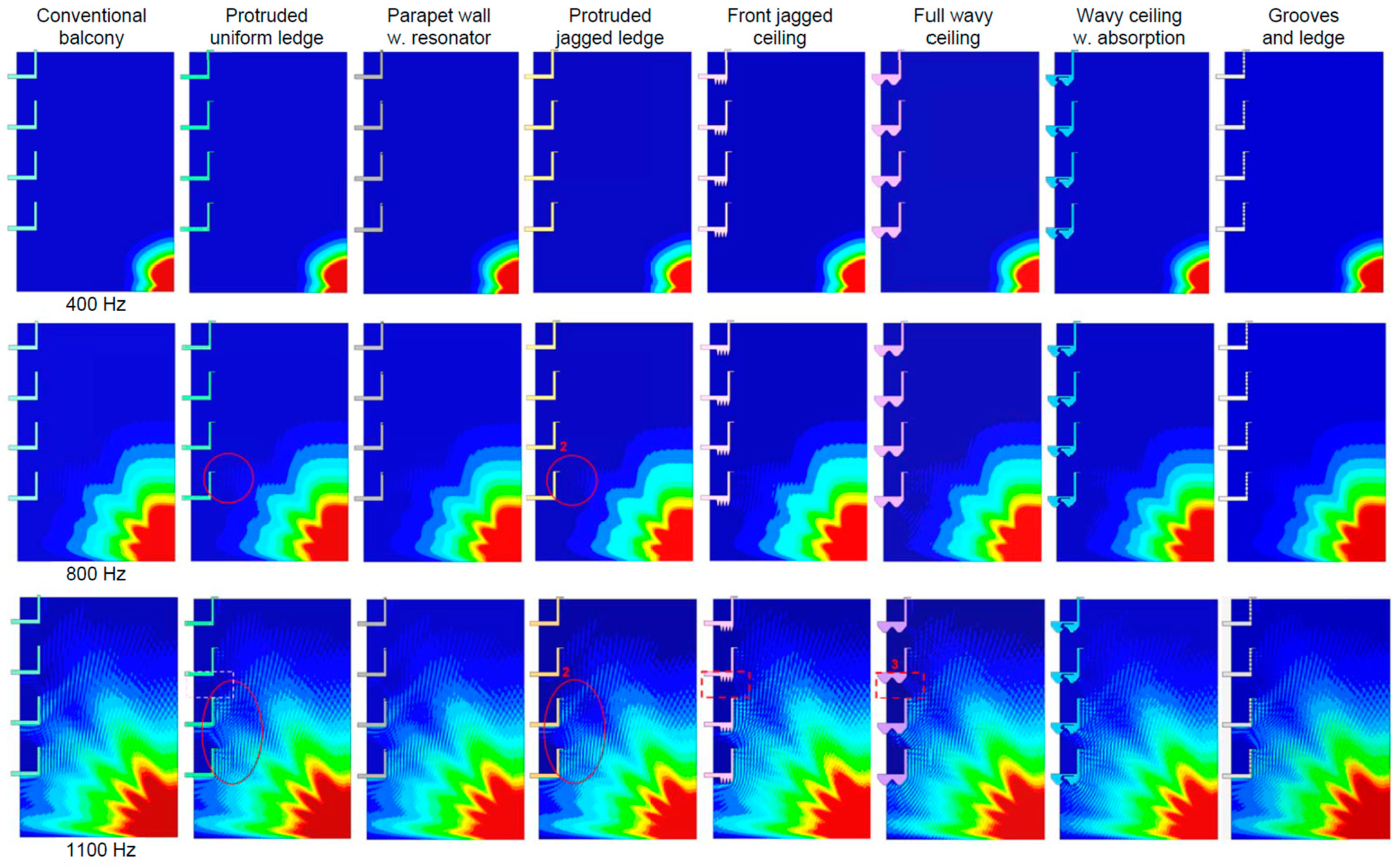
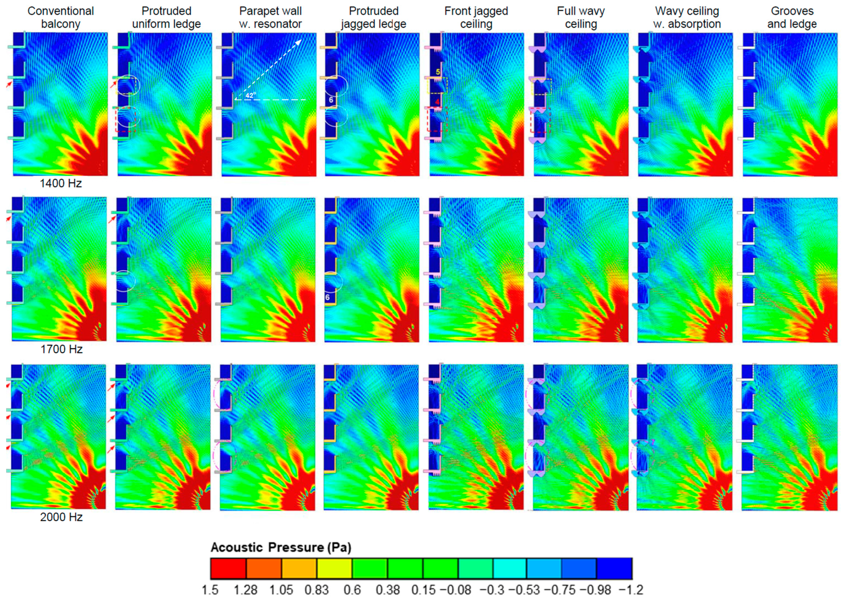
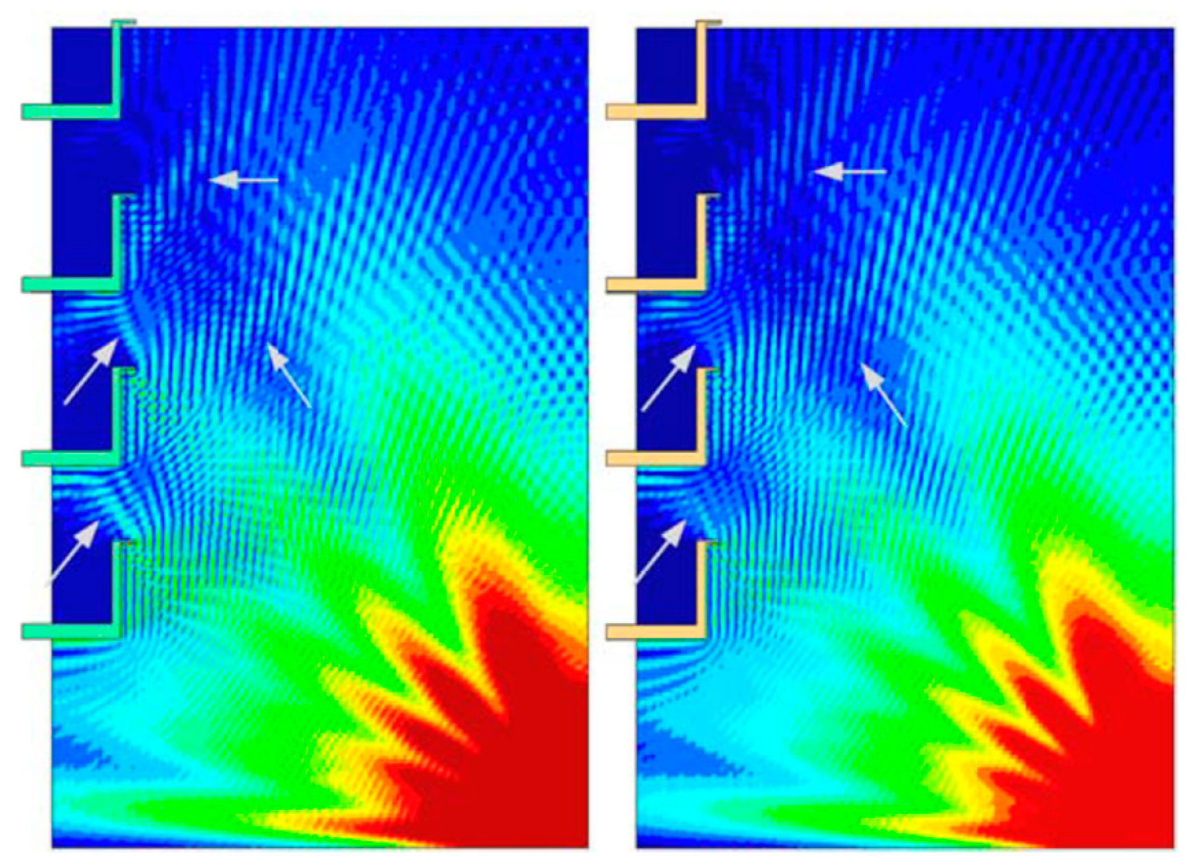
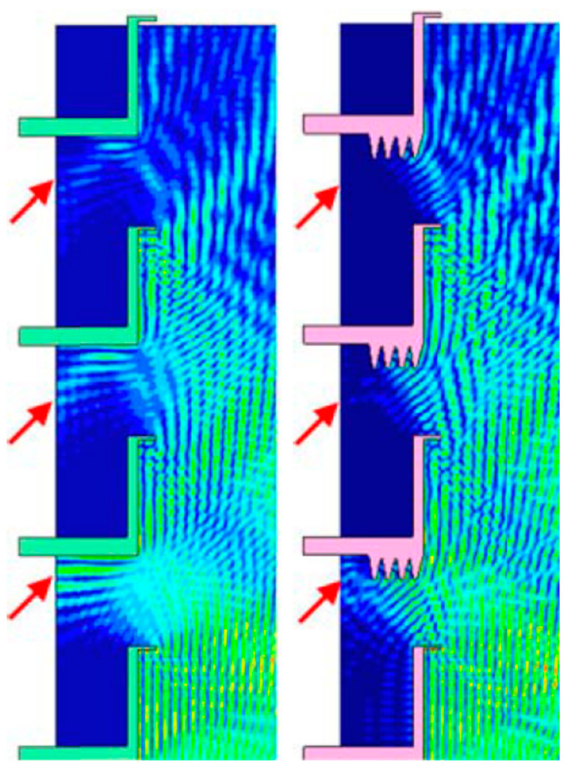
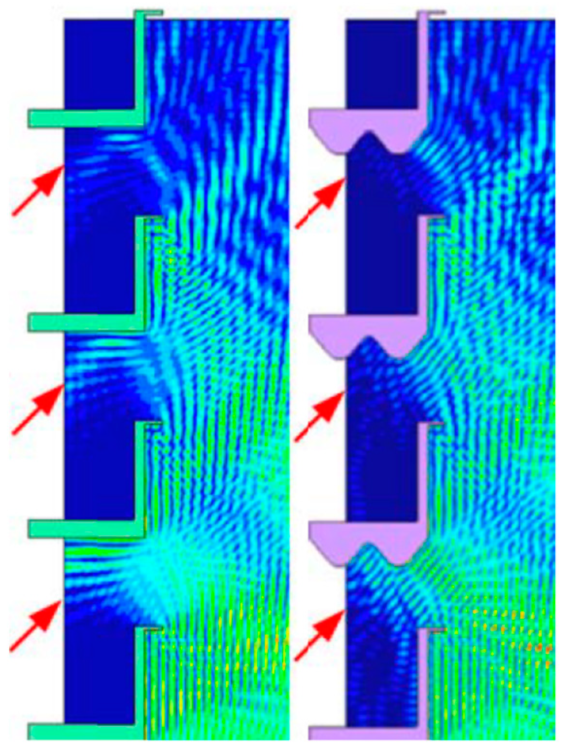
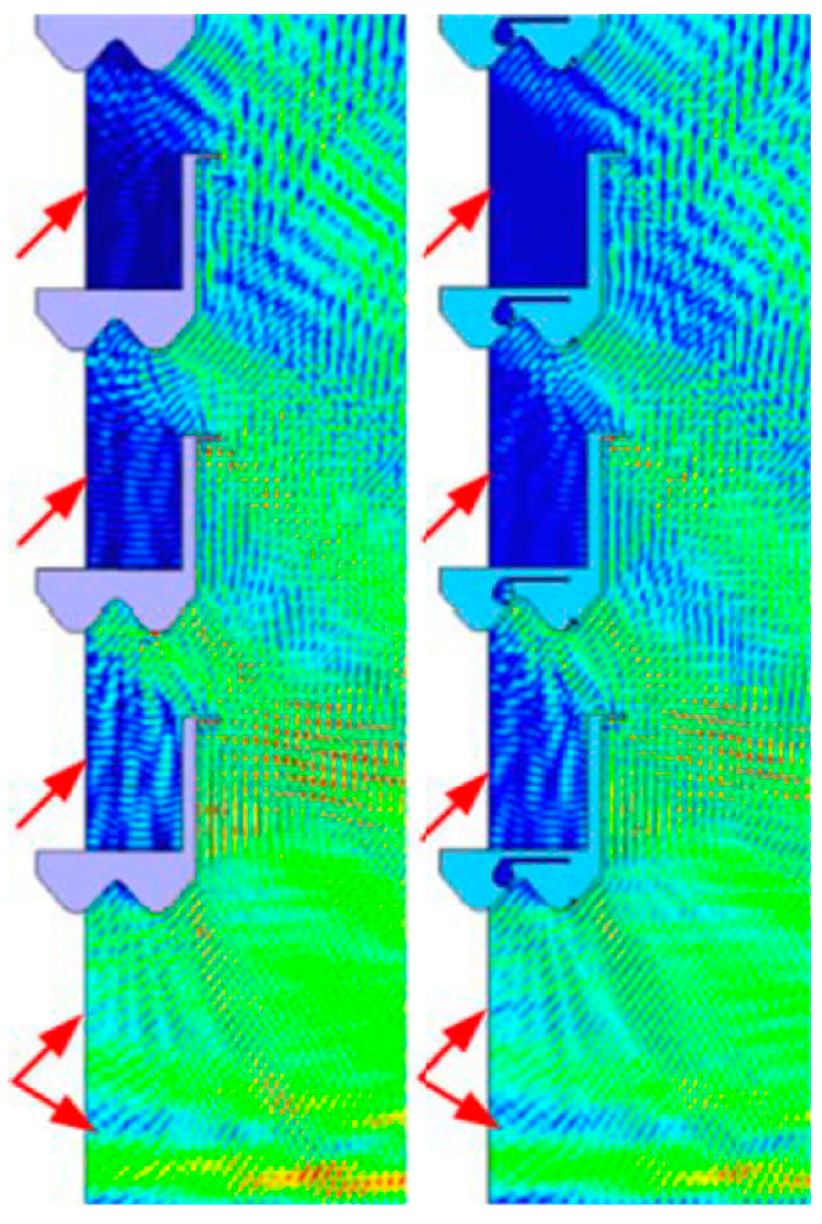
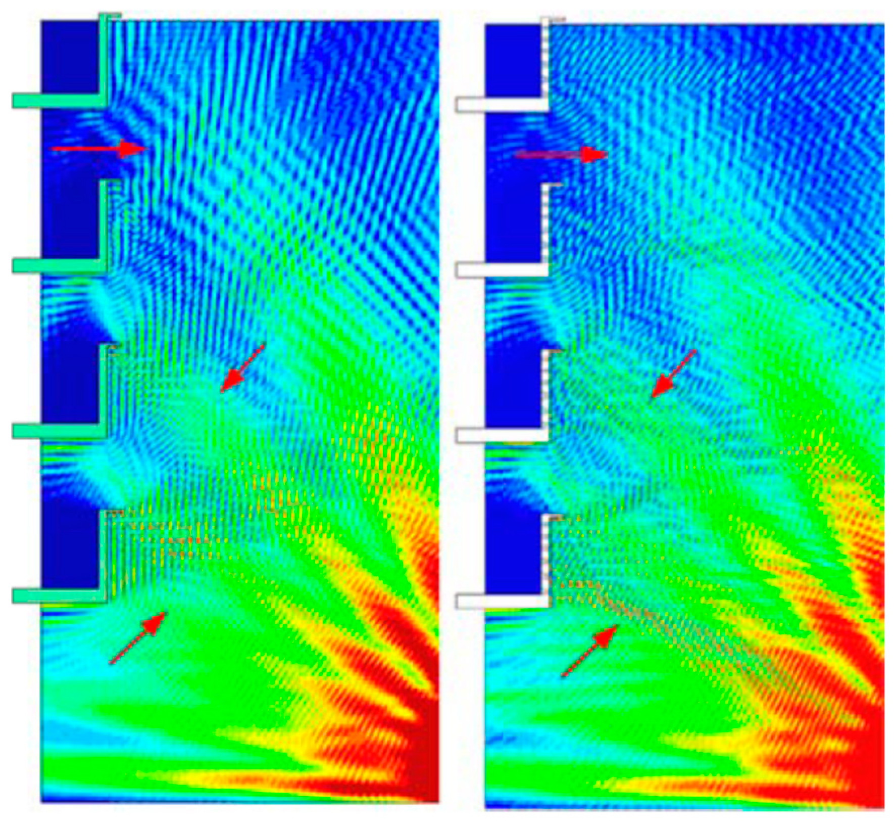
3.1. Evaluation of Balcony Designs Using Acoustic Pressure Contour Plots

Figure 3 illustrates the acoustic pressure in the air surrounding various balcony designs in different frequency steps. The color contours are consistently fixed across all figures to ensure a fair comparison of sound pressures, with blue and red representing low and high acoustic pressures, respectively. FE analysis was employed to present the complete field of pressure contours, offering more detailed information about the precise locations of loud and soft noises, compared to theoretical or ray methods. The leftmost figures depict acoustic pressures around the standard balcony, enabling the assessment of additional IL resulting from modifications to the balcony ceiling or parapet wall. Not all plots of every frequency step are included in Figure 3. This is because in low frequencies, the pressure contours are typically highly similar, as many design solutions are only meant to be effective at above 800 Hz. Figure 3 reveals variations in the noise field within and outside the balconies for different designs, with higher pressure closer to the sound source. As frequency increased, pressure contours near the sound source exhibited more “loops” or undulations, which were attributed to the ground impedance boundary condition causing the reflection of noise and the formation of standing waves between the source and the ground. This resulted in more jagged-shaped contours.
At 1.1 kHz, the jagged ledge (Case 4) diffused less noise into the balcony on the second floor, compared to the uniform ledge in Case 2. Case 4 also exhibited the lowest acoustic pressure in the void deck regions on the first floor. Furthermore, the front jagged ceiling (Case 5) reflected less noise into the balcony, compared to the full wavy ceiling (Case 6). The full wavy ceiling, in turn, displayed the highest acoustic pressure at the void deck for this frequency.
At 1.4 kHz, a comparison of Cases 1, 2, and 4 revealed that the jagged ledge was best able to diffuse noise in front of it, followed by the balcony with the protruded uniform ledge. The conventional balcony without an extended ledge at the front parapet wall yielded the highest acoustic pressure near the top regions of balconies on the second, third, and fourth floor. Both the front jagged ceiling and the full wavy ceiling designs diffused and lowered the acoustic pressure on the balcony ceilings, compared to the Cases of the protruded jagged ledge and uniform ledge. The wavy ceiling with absorption treatment using Helmholtz resonators and cavities showed better absorption at the ceiling and reduced noise near to the ceiling, compared to the full wavy ceiling without any absorption treatment. Again, at 1.4 kHz, the exterior noise contours for all the designs looked very similar, implying that there was minimal change in the noise reflected away from the building façade. The angle of reflection from the parapet wall was, with regard to the horizontal, measured at about 42°, with the noise being reflected upwards.
At 1.7 kHz, noise reflection to the balcony ceilings was observed to be more defined, especially for designs without ceiling treatments, such as Cases 1, 2, 3, 4, and 8. The balcony design with slot holes and ledge (Case 8) showed greater interference of reflected noise with the incident noise outside the balcony than the conventional balcony (Case 1) and the counterpart with the uniform ledge (Case 2). The former revealed dispersion of the reflected noise from the façade, in the horizontal and slightly downward direction, while Cases 1 and 2 had reflection rays that generally pointed diagonally upwards. At this frequency, we observed that both the front jagged and full wavy ceiling are likely not recommended for lower floors, as they can, compared to other designs, worsen performance by promoting increased noise entry into the balcony. However, both designs are recommended for higher floors—at least above the fourth floor—as their noise mitigation performance is better than other designs. The jagged ledge can better diffuse noise at the trailing edges near the parapet wall, compared to the uniform ledge design, and this effect is evident for all floors of the building. The pressure contours also showed that the slot holes or groove design performed just slightly better than the conventional balcony, implying that modifications to parapet external surfaces do not considerably improve noise attenuation around this frequency.
At 2 kHz, we observed that the interference of the reflected noise with the source was rather significant, with the angle of the reflected noise being maintained at around 42° from the horizontal. We also observed that the front jagged ceiling design seemed to reflect off the incident sound at a greater range of angles at the second floor, when compared to the full wavy ceiling design. This implies that for a cluster of buildings that may be very closely situated together or for two buildings that are facing each other, both the slot or groove parapet and the front jagged ceiling may reflect noise to the opposite building instead of projecting it upwards away from the buildings.

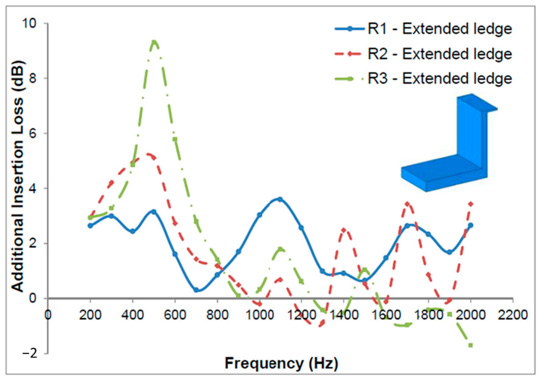
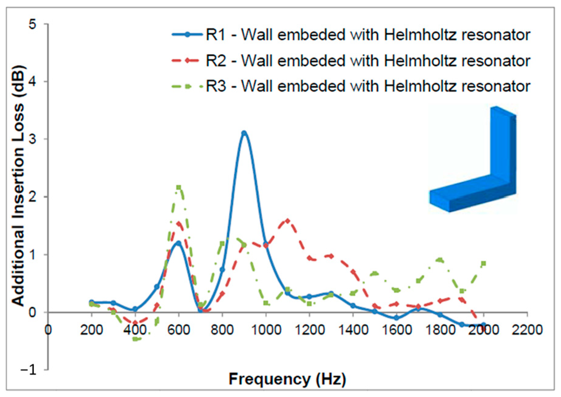
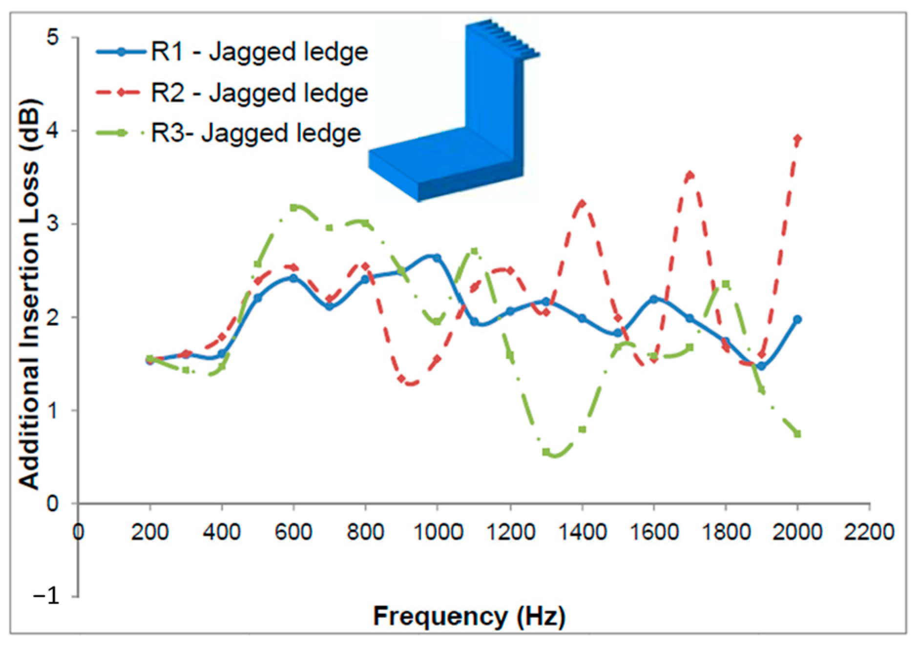
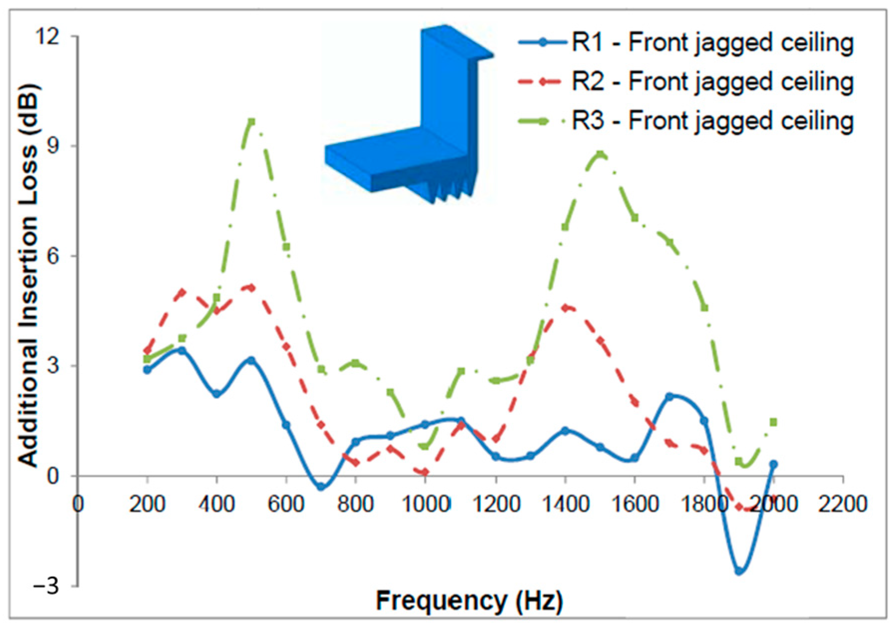
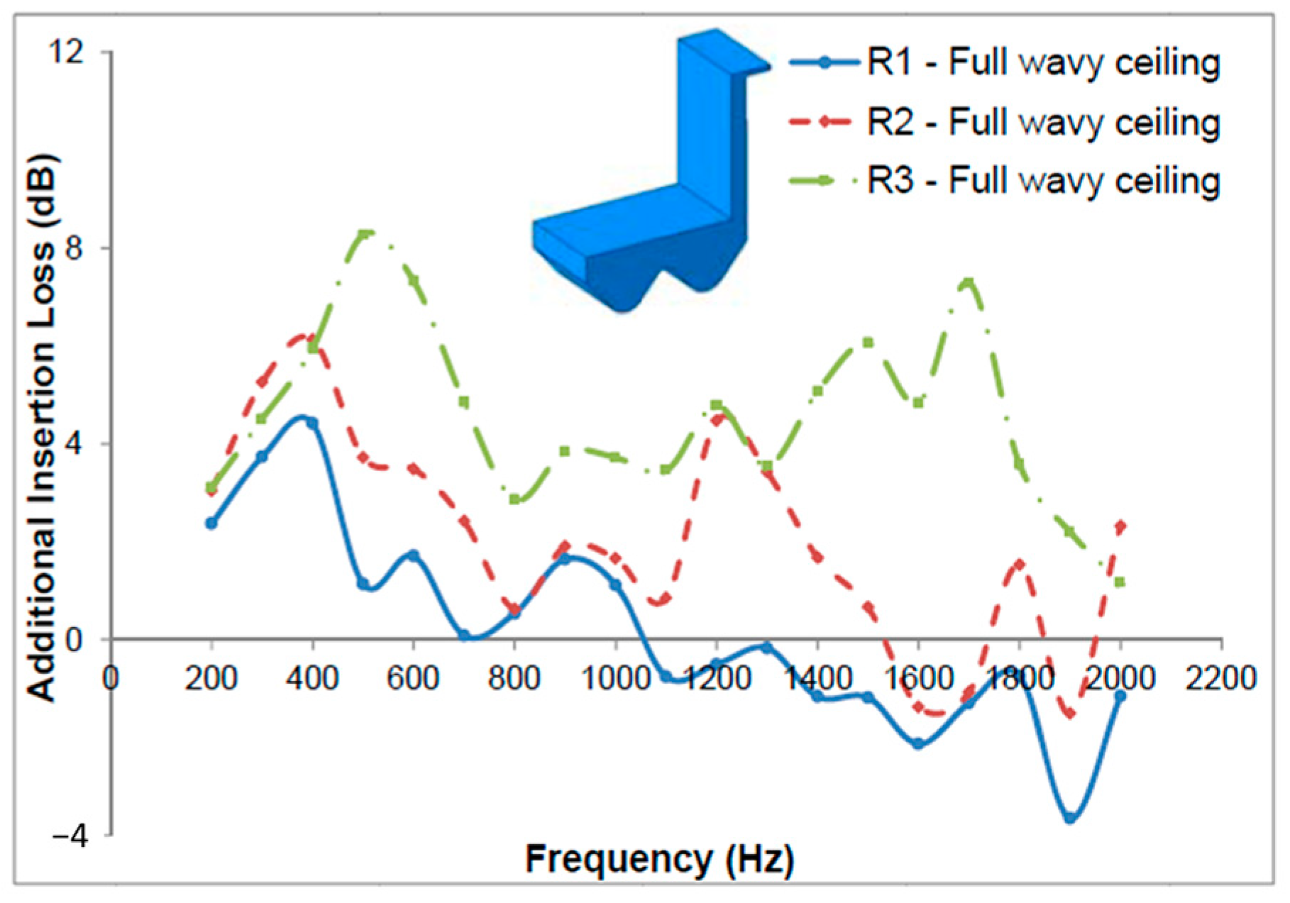
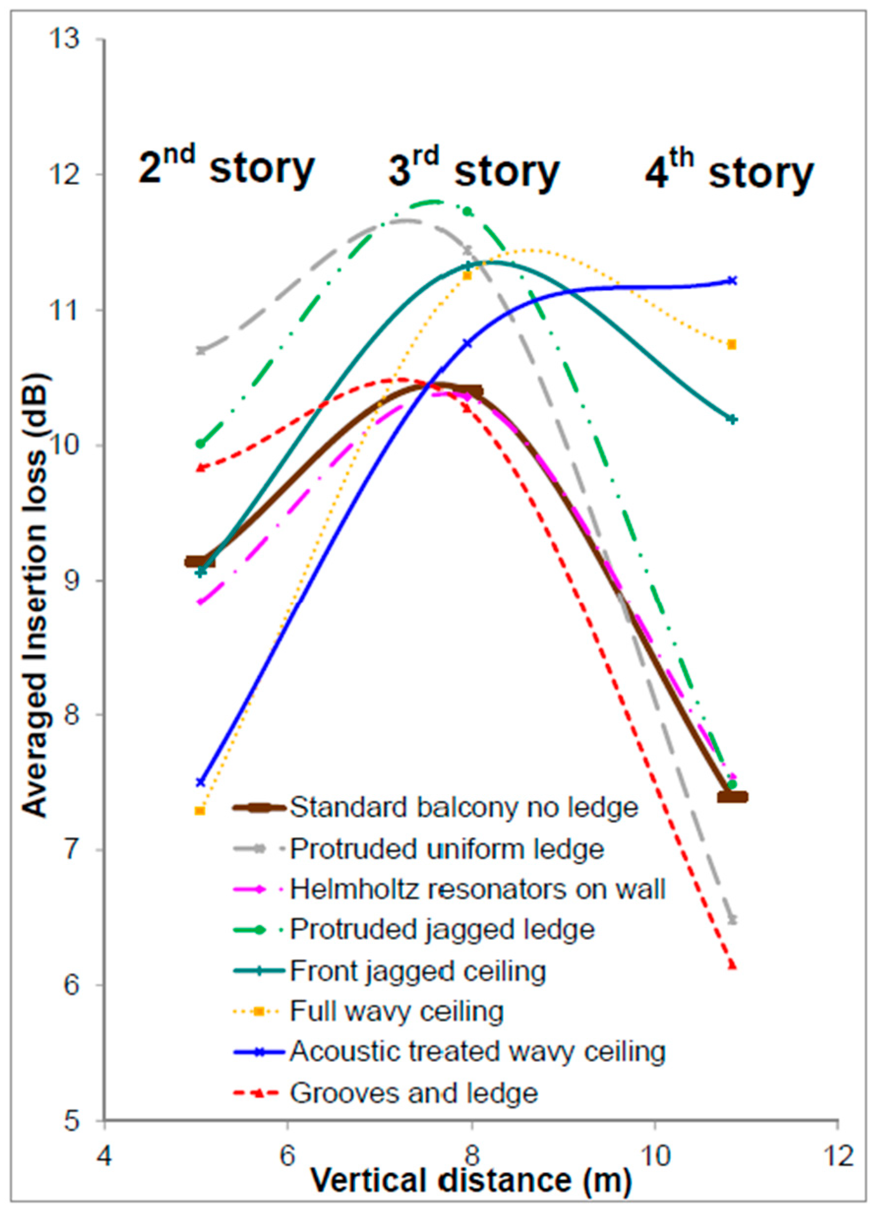
3.2. Quantitative Analysis of the Insertion Loss

In the analysis, the acoustic pressures of the nodes at receiver regions R1 to R3 for each frequency step were extracted and averaged before the values were converted to SPL. The resulting sound pressure levels were then utilized to calculate the additional IL characteristics, defined as the difference in SPL between the specific balcony design under consideration and the standard balcony without an extended ledge. IL is the preferred metric for evaluation because the conventional front parapet balcony serves as the default construction in many countries. The focus of the investigation is on understanding the additional IL achievable through the modification of this default design. A negative IL value indicates sound amplification, while a positive IL implies further sound attenuation. In an apartment complex, various sources, such as noises from vehicles, construction equipment on nearby construction sites, or outdoor events (like markets or grassroots events) may contribute to the acoustic environment. The effectiveness of different balcony types as screening devices for different noise signatures or profiles has not been extensively reported. The presentation of the IL spectra allows for the assessment of the suitability of each design against different noise sources. Figure 4, Figure 5, Figure 6, Figure 7, Figure 8, Figure 9, Figure 10 and Figure 11 depict plots of additional IL versus frequency for the various designs.
The literature [4,7] has indicated that direct sound and ceiling reflection are the most dominant effects, leading to a primary focus on the design of the parapet, ledge, and ceiling in balcony solutions. Figure 4 illustrates that the protruded ledge (Case 2) resulted in a positive impact on reducing noise entering the apartments from the balcony. The 25 cm protruded ledge (5 cm thickness) exhibited IL peaks at 500 Hz and 1100 Hz. The results highlighted an improvement in IL performance at below 800 Hz with increasing floor heights (R3 > R2 > R1). At the fourth floor, the peak IL reached 9.4 dB at 500 Hz. On lower floors, the performance was relatively consistent without very high peaks or troughs. However, some negative IL was observed for higher stories, which was partially attributed to resonant modes between the ledge and the ceiling, particularly when the noise frequency exceeded 1.6 kHz. The suitability of this design depends on the expected noise sources. If noise primarily originates from construction or traffic and falls below 800 Hz, the effectiveness of the protruded ledge increases with floor heights. However, if noise sources are from outdoor markets or events, this design may not be as useful, particularly for higher frequencies. The design may be more suitable for middle floors (second to fourth floors) because of the observed performance—albeit relatively low IL—over nearly the entire frequency range of interest. For higher floors, the protruded ledge alone should not be used. This is because although the design could achieve high positive IL at below 800 Hz, its performance could be detrimental at higher frequencies. Therefore, additional attenuation measures, such as ceiling treatments or further extension of the ledge, are necessary for higher floors to cover a broader frequency band.
In Figure 5, we observed that the wall-embedded Helmholtz resonators (Case 3) effectively mitigated noise ingress into the balcony. The two resonators, designed to operate at 900 Hz and 1.2 kHz, demonstrated distinct IL peaks at both frequencies. Notably, the second IL peak on the third floor, R2, exhibited a broader bandwidth, which is a desirable characteristic. The embedded resonators were strategically positioned near the tip of the parapet wall to facilitate absorption and resonance in proximity to the ledge where noise ingress occurs (the opening between the ceiling and the wall).
As depicted in Figure 5, the two small resonators generally yielded lower IL, with the highest IL of 3.1 dB occurring at 900 Hz for the balcony on the second floor. The overall IL values ranged from about 1 to 1.5 dB reduction across the spectrum, which is lower than the extended ledge design and many other solutions. Typically, the greater the volume of the cavity and the number of embedded resonators, the better the attenuation [28]. A favorable trait of this design is that it yielded a very wide range of frequencies with positive IL, making it seemingly applicable to balconies on any floor. On lower floors, the peak IL was at 900 Hz, gradually shifting to peak at 600 Hz as the number of floors increased.
Figure 6 presents the IL profiles of the jagged ledge (Case 4), showcasing a consistently positive IL across the entire frequency range from 200 Hz to 2 kHz without any negative IL observed. However, the magnitude of the positive IL was not as superior as the jagged or wavy balcony ceiling designs. The design did not show any dominant performance because of the lack in distinctive peaks. Some undulation in the IL profile for R2 was observed above 1.4 kHz, similar to that observed for the uniform protruded ledge design. These peaks and troughs within the spectrum plots for similar frequencies are likely standing wave resonance effects due to the balcony space size.
Figure 7 shows that the jagged ledge had the effect of diffusing noise near the balcony and reducing the magnitude of reflected noise (indicated by white arrows in the figure). This design exhibited an overall higher IL profile than Case 3 but lower IL peaks than Case 2. Similar to the other two designs, the jagged ledge showed that higher floors provided better attenuation at below 1.1 kHz. However, at above 1.1 kHz, the middle floor showed better attenuation.
Figure 8 shows the balcony IL characteristics for the front jagged ceiling and parapet ledge design (Case 5). With the implementation of both a beneficial balcony ceiling and wall ledge, significant noise reduction in the balcony was observed. Throughout the three different stories, the IL was also mostly positive. Two distinctive peaks in the IL spectrum were observed, one dominating at around 500 Hz and another at around 1.4 kHz. The two main peaks for insertion loss were mainly due to diffraction and interference effects of sound. The first peak was caused by the ledge design, as also observed in Figure 4, while the second peak was due to the jagged diffuser design of the balcony ceiling. The analysis demonstrated that while the ledge (depending on its depth) was effective at attenuating noise at the lower frequency range, designs for the balcony ceilings would improve noise attenuation in the middle to higher frequency range. Hence, the combination of the two designs allowed for a more comprehensive attenuation coverage, with a broader attenuation bandwidth. The combination of the two designs, likely due to some overlapping influence, also helped raise the IL profiles so that almost the entire IL curve was positive. However, it was noted that the IL from 800 Hz to 1.2 kHz was still relatively low. Therefore, one way of further improving this design might be to include wall-embedded Helmholtz resonators whose effectiveness from 800 Hz to 1.2 kHz was shown in the IL plots. Finally, the plot also shows that the several peaks and troughs from 1.4 kHz were non-existent, meaning that this front jagged ceiling design can effectively break down or disrupt room standing wave resonance effects, as previously observed in Figure 4 and Figure 6.
Figure 8 also revealed that the jagged ceiling diffuser became increasingly more effective in noise attenuation on higher floors further away from the source. This design may be considered for any balconies that are three stories in height and above. Figure 9 compares the acoustic contours of both the uniform ledge and jagged ceiling designs and illustrates how the jagged ceiling could diffract and diffuse the noise at the balcony ceiling at 1.5 kHz, reducing ceiling reflections and limiting noise ingress in the apartment as shown by the regions indicated by the red arrows in the figures.
Figure 10 shows the IL characteristics for the full balcony wavy ceiling design (Case 6). Again, several peaks were observed for the middle to higher floor balconies. The peak at around 500 Hz was attributed to the effect of the protruded ledge, while the other peaks, from 1.2 kHz to 1.7 kHz, were likely because of the wavy ceiling. Both the front jagged and wavy ceiling designs yielded good mitigation performance at higher frequencies, implying that they are also more suitable when considered against the human vocal range.
The comparison of Figure 8 and Figure 10 showed that the full wavy ceiling yielded poorer IL characteristics, with peaks lower than those from the front jagged ceiling, and that there were more frequencies in the lower and middle stories with negative IL. The full wavy ceiling was investigated because it is more aesthetically pleasing than the front jagged ceiling. The design showed improvement in reducing noise into the balcony, particularly at higher floors. The spread of the effective bandwidth for positive IL of the fourth floor was much better than that of the front jagged ceiling, in which poorer performance was observed from 800 Hz to 1.2 kHz. The negative IL of the second floor implies that implementing the full wavy ceiling design could cause increased noise on lower floors. Similar to the front jagged ceiling, we noted that when floors were higher, ceiling design was more effective. Hence, this design may be suitable for higher floor balconies, depending on the proximity of the sound source and ledge depth. Figure 11 compares the acoustic contours of the uniform ledge and full wavy ceiling designs, revealing how the wavy ceiling was able to reduce noise reflections at 1.5 kHz and limit noise ingress into the apartment as shown by the regions indicated by the red arrows in the figures.
Figure 12 shows the IL characteristics of the same wavy ceiling design but with acoustic treatment (Case 7). The acoustic treatment consisted of two small Helmholtz resonators near the trough of the first wave at the front of the balcony, and a large cavity near the crest of the second wave in the middle of the balcony. Both resonators and the cavity helped promote sound absorption at their designed frequencies. The comparison of Figure 10 and Figure 12 showed that there was indeed improvement in the IL performance of the latter design. In particular, the IL peaks for the balcony on the fourth floor were higher than before, and the negative IL for the balcony on the second floor was improved. Improvements for frequencies above 1.7 kHz were significant, with new peaks being introduced for the fourth floor, while the IL for the other two floors were generally pushed up. Figure 10 and Figure 12 also showed that acoustic ceilings can effectively disrupt room standing wave resonance effects, compared to Figure 4 and Figure 6. Although there is minor insertion loss improvement of the wavy ceiling with Helmholtz resonators, the disadvantage is that it generates greater IL fluctuations from 1.5 kHz that may not be as comfortable for the residents, due to the incorporation of the resonators. One recommendation might be to use noise absorption materials for the ceiling, rather than incorporating the resonators, with the aim of achieving better performance.
Figure 13 shows the acoustic pressure contours between the untreated and treated wavy ceilings at 1.5 kHz, which evidently showed, from the regions indicated by the red arrows, that the treated ceiling had less noise reflection to the lower portion of the balcony. It is of interest to note that the acoustic pressures at the void deck also showed lower intensity for the ceiling with acoustic treatment. This implies that to achieve noise control on the void deck, potted plants should be placed near the entrance and the void deck ceiling should be treated, to reduce noise ingress if the floor cannot be modified.
Figure 14 shows the IL characteristics of the balcony design with both uniform ledge and slot holes at the exterior surface of the front parapet wall. In comparing this figure with Figure 4 (balcony with uniform ledge only), we observed that the distinct IL peak at 500 Hz of the latter design was no longer reflected in the IL plot for the grooved wall. Instead, we observed two new IL peaks at 300 Hz and 600–700 Hz. Although there were multiple IL peaks, the peak magnitudes were much lower than those observed for the ceiling designs. The grooves on the parapet mostly affected IL performance at the lower frequency range. In particular, acoustic attenuation on the third floor was even better than that on the fourth floor, at 300 Hz.
The second peak, at around 700 Hz, is desirable when compared to Case 2 (balcony with uniform ledge), as the latter design showed insignificant IL at around this frequency range. The grooved wall design was also shown to be better at attenuating noise on the lower floors than Case 2 and 5–7. Hence, the grooved wall design may be considered for use on the lower floors. Figure 15 shows the pressure contours between the slot hole and no slot hole parapet wall designs at 1.8 kHz, which evidently showed, from the regions indicated by the red arrows, that the slots could diffract incident noise horizontally and downwards, instead of upwards. Such a design may be detrimental for residential buildings that are closely facing one another. Therefore, this design is not an effective design because only frequencies below 1.1 kHz can be improved; beyond this, the performance is erratic, with alternating positive and negative IL over the spectrum.

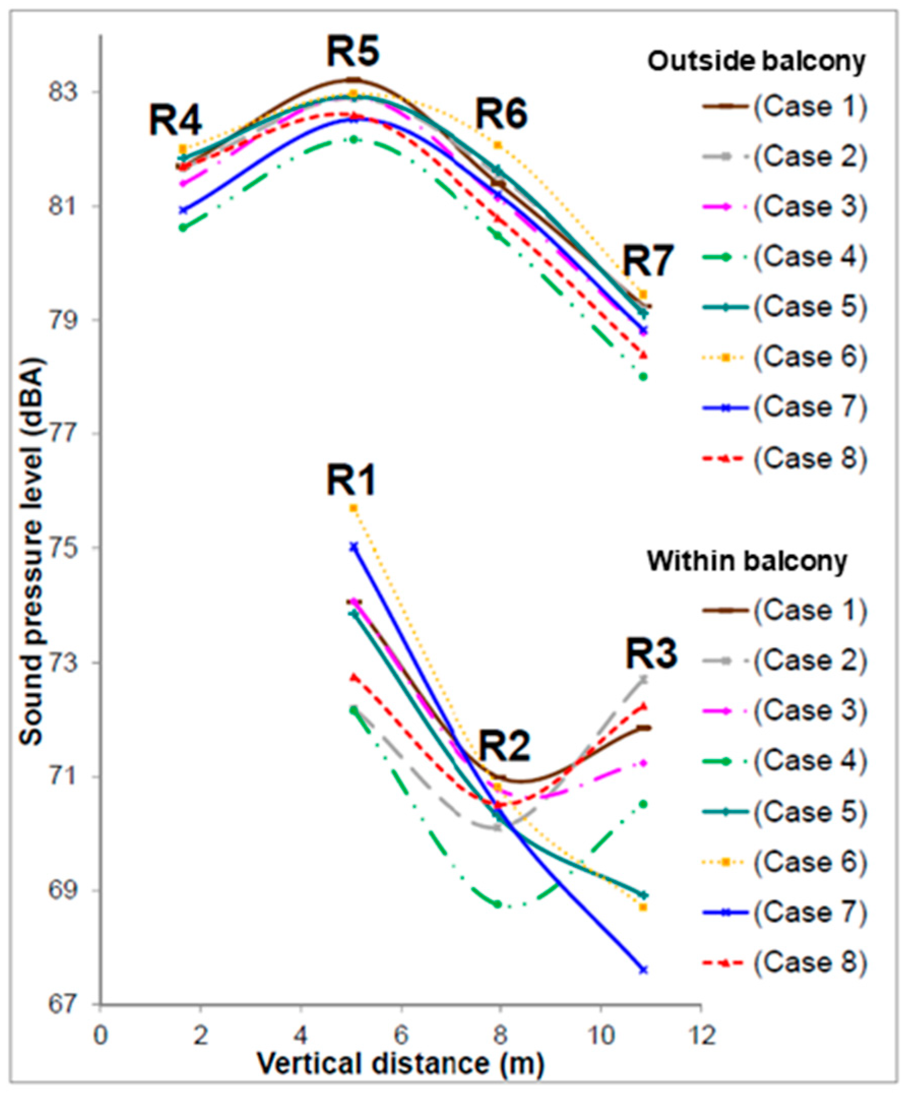
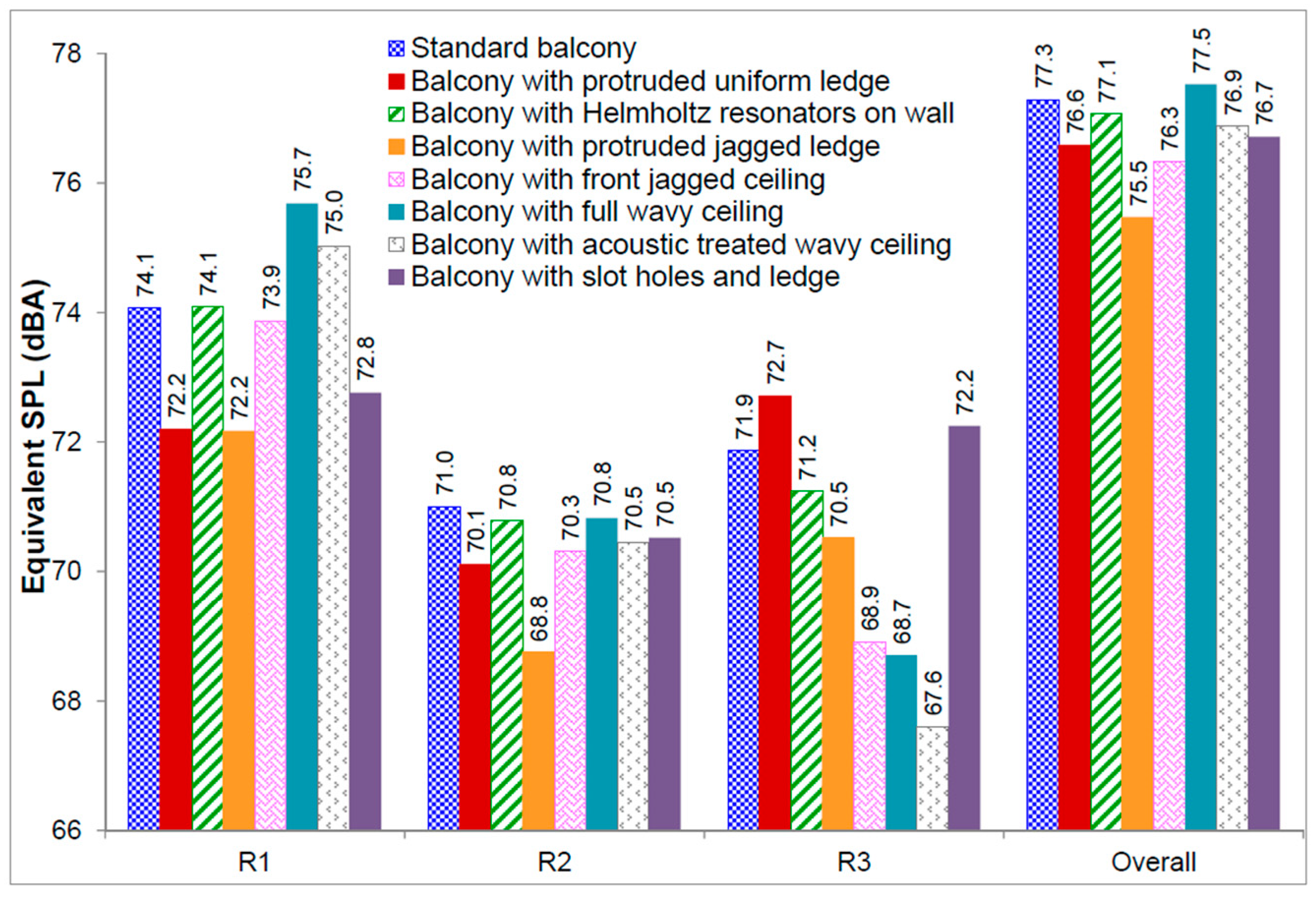
3.3. Analysis of Sound Pressure Levels at Receiver Locations

The SPL in pre-designated regions were obtained to quantitatively assess the acoustic performance of the balcony designs. Regions marked R1 to R7 (see Figure 2), each measuring 0.5 m by 0.5 m, were selected to evaluate the SPL, both inside and outside the balcony. R1 to R4 helped to monitor the SPL on the void deck and the second to fourth floor, respectively. R5 to R7 were defined as receiver locations 1 m outside of the parapet walls, allowing the analysis of the SPL of the incident and reflected noise near the façade. Another motivation for extracting SPL at regions outside the balcony is to evaluate the effect of reflected or diffracted noise on the environment, to ensure the noise does not get overly amplified, and cause a problem for nearby residential blocks.
For each frequency, the acoustic pressures of the nodes within the regions were averaged before being converted to SPL. These values were then applied with the A-weighting. Here, consider that spectrum analysis was complex because the performance of one design can be better than another, with respect to a given frequency. We adopted a single number metric—equivalent SPL (LAeq)—to account for the contribution of each frequency (Li), allowing us to make a direct assessment of the designs. The formula for obtaining the equivalent SPL is given by
L A e q = 10 log i = 1 n 10 0.1 L i
By combining the SPL contributions across different frequencies, the resulting equivalent SPL at the receiver locations, as a function of vertical distance from the ground, is shown in Figure 16. In this figure, it is shown that the noise outside of the balcony ranged from around 82.5 dBA on the second floor to around 79 dBA on the fourth floor. The natural noise attenuation over a distance of about 6 m between R5 and R7 appeared to be relatively linear. For R5 to R7, we observed that for a doubling of sound propagation distance, there was a SPL reduction of about 4 dB. Although not presented here, the variation in SPL for these exterior receivers can be similarly plotted as a function of the absolute distance from the sound source or as a variation in elevation angle from the source to the receivers. The latter showed similar correlations, and hence only Figure 16 is presented. Between the various designs, the observed deviations were about 2 dBA. This can be attributed to both interference and reflection effects from the building façade, which is not a plane surface owing to the presence of the balconies. Due to the proximity of R5 to R7 near the building façade, the noise attenuation over distance is typically lower than that for an unobstructed noise source. Case 4 (Jagged ledge) and Case 8 (Front parapet with grooves) yielded overall lower SPL at the exterior regions, compared to other designs. This implies that the designs are less acoustically detrimental to nearby residential blocks. This may be intuitive because the jagged ledge tends to diffract and diffuse incident noise, while the grooved parapet wall allows absorption and dissipation of sound.
We also observed that the noise level at R4 (void deck) was lower than that at R5 (second floor) and about the same as that at R6 (third floor). This observation shows the effect of the void deck ceiling in reducing noise at this location because, by extrapolating R5 upwards on the graph, the equivalent SPL would likely be around 85 dBA at the same vertical distance from the ground. This understanding demonstrates that the void deck could, when compared to the exterior at the same elevation, reduce noise by around 4 dBA. The acoustic pressure contours in Figure 3 also corroborated this finding. However, noise reduction at the void deck was small compared to at R1 to R3, which were within the balcony of the upper floors due to the screening effect of the parapet.
The SPL curves for R1 to R3 were relatively far below the plots for R4 to R7, implying a significant reduction in noise at the respective balconies. Subtracting the “within balcony” values from the corresponding “outside balcony” values in Figure 16 would allow the evaluation of noise reduction for each balcony design. Figure 17 shows the effectiveness of the various balcony designs in reducing noise on different floors in terms of IL. The IL values are in the same range as those reported by Li et al. (i.e., around 6 dBA at lower floors) [4] and Yeung (i.e., around 5 dBA) [13]. The thick line represents the performance of the standard balcony without a ledge. On the fourth floor, many of the balcony designs had a lower IL due to ceiling reflection. The protruded jagged ledge and front jagged ceiling designs were superior to the standard balcony because their IL curves were entirely above it. Generally, the “within balcony” values were observed to be about 10 dBA lower than the “outside balcony” values, implying that the use of a balcony with a front parapet wall should readily achieve such an amount of noise reduction. The IL plots for many balcony designs tended to be “N-shaped,” indicating that beyond a certain elevation, noise attenuation in the balcony could deteriorate. This finding is similar to the acoustic treatment study by Lee et al. [5] who reported that the noise reduction fluctuated, depending on the floor of the building and the incidence angle. However, the front jagged and full wavy ceiling designs (Cases 5 to 7) yielded curves that were the least “N-shaped,” revealing that these two designs could be more robustly used across balconies at different floors. Table 4 shows the equivalent A-weighted IL for the various balcony designs. The bracketed values are the additional insertion loss calculated with reference to Case 1. The standard balcony yielded around 9 dBA of noise attenuation, which is consistent with that reported by Tang at an elevation angle of 1 radian [7], and Lee et al. (i.e., up to 9 dBA and 7 dBA, both with and without absorbing materials) [5], May (i.e., 7–8 dBA reduction) [6] and Hammad et al. [14]. The ceiling designs (Cases 5–7) showed about 3 dBA reduction compared to the standard balcony at R3 (4th floor), which is consistent with reported ceiling treatments producing around 4 dBA reduction [6].
The protruded jagged ledge (Case 4) and jagged ceiling (Case 5) solutions yielded the highest overall IL performance among the three analyzed balcony floors. These two designs also, when reference is made to Case 1 (standard balcony without ledge), offer positive additional IL of 0.7 dBA and 0.9 dBA, respectively.
Figure 18 shows the A-weighted equivalent SPL of the various designs in a bar chart. The leftmost bars for each set represent the SPL of the standard balcony and serve as a benchmark for the performance of the various designs. The lower the SPL, the better the sound attenuation at the frequency. From the figure, we observed that several designs performed well in some regions but performed poorer in other regions. On the second floor, the balcony with the protruded uniform ledge and jagged ledge performed well by reducing around 2 dBA, compared to the standard balcony. However, on the fourth floor, the protruded ledge performed worse than the standard balcony, and the better-performing designs are the untreated and treated wavy ceiling. Although the jagged ledge had a similar performance to the uniform ledge on the second floor, the jagged ledge showed better performance on the higher floors (close to 2 dBA for the fourth floor). Comparing both designs, the jagged ledge design can potentially further reduce up to about 1.4 dBA more than the uniform ledge design. Compared to the standard balcony without ledge, the jagged ledge design can potentially reduce about 2 dBA overall, which is better than the uniform ledge design, which only reduced about 0.8 dBA.
Furthermore, the front jagged ceiling performed much better than the full wavy ceiling, signifying that there is no need to install a full ceiling for the balcony, but only for the outer region. Figure 18 also shows that for the balcony with either jagged or wavy ceilings, the higher the floor, the better the attenuation performance. Based on the results, a combination of protruded jagged ledge on the lower floor and jagged or wavy balcony ceilings on the higher floor would most likely result in the lowest noise ingress into all the residential units.
The slot holes design had about the same performance as the balcony with protruded uniform ledge. The former performed poorer on lower floors and slightly better on higher floors, which shows that the grooved wall design is not an effective strategy for limiting noise ingress into the apartment.

4. Conclusions

Eight unique designs, incorporating curved surfaces, diffuser edges or Helmholtz resonators, were proposed and evaluated for noise mitigation, showing their useful attenuation bandwidth. The IL plots for many balcony designs tended to be “N-shaped”, indicating that, beyond a certain elevation, noise attenuation in the balcony could deteriorate. However, the front jagged and full wavy ceiling designs (Cases 5 to 7) yielded curves that were the least “N-shaped”, revealing that these designs could be more robustly used across balconies on different floors.
Case 4 (jagged ledge) showed about 2 dBA reduction over the standard balcony across all floors and provided stable positive IL across 200 Hz to 2 kHz. This structural design can be considered superior to acoustic treatments [5] because, in obtaining similar noise reduction, it is both cheaper and easier to incorporate the ledge as part of balcony construction (rather than as absorption materials, which are more cost sensitive to affix and maintain. Case 4 (jagged ledge) and Case 8 (front parapet with grooves) yielded an overall 1.5 dBA lower SPL at the exterior regions, compared to other designs. This implies that the designs are less acoustically detrimental to nearby residential blocks, which is due to the diffractive and absorptive nature of the designs, respectively. The jagged ledge design is more effective on lower floors while the jagged ceiling design is more effective on higher floors. Based on our results, a combination of Case 4 (protruded jagged ledge) on the lower floor and Case 5 (jagged balcony ceiling) for the higher floor would result in the lowest noise ingress into all the residential units and would be capable of achieving more than 3 dB in noise reduction. Our study highlights that while the spectrum characteristics of acoustic absorption materials may be less tunable, trading reduced head space for thicker material for greater absorption can enable the ceiling curvatures to actually be tuned (e.g., every two to three floors up the high-rise), which will more effectively reduce noise ingress and possibly improve the architectural façade outlook.
We also found that, while acoustically treating ceilings produced a minimal improvement in overall performance, the costs required for fabrication and maintenance may not sufficiently justify its full-scale implementation.

Author Contributions

Conceptualization, L.B.T.; methodology, L.B.T.; validation, L.B.T.; formal analysis, L.B.T.; resources, L.Y.L.A.; data curation, L.B.T.; writing—original draft preparation, L.B.T.; writing—review and editing, L.Y.L.A.; visualization, L.B.T. and L.Y.L.A.; supervision, L.B.T.; project administration, L.B.T. and L.Y.L.A. All authors have read and agreed to the published version of the manuscript.

Funding

This research received no external funding.

Data Availability Statement

The data presented in this study are available on request from the corresponding authors. The data are not publicly available due to confidentiality issues in certain areas.

Acknowledgments

The authors would like to acknowledge the contribution of Kian-Meng Lim and Heow Pueh Lee, National University of Singapore (NUS), for contributing technical advice to this research.

Conflicts of Interest

The authors declare no conflicts of interest.

Abbreviations

The following abbreviations are used in this manuscript:
FEFinite Element
ILInsertion Loss
SPLSound Pressure Level

References

  1. Chan, A.L.S. Investigation on the appropriate floor level of residential building for installing balcony, from a view point of energy and environmental performance. A case study in subtropical Hong Kong. Energy 2015, 85, 620–634. [Google Scholar] [CrossRef]
  2. Ting, K.H. Tropical green building rating systems: A comparison between Green Building Index and BCA Green Mark. In Proceedings of the 2012 IEEE Business, Engineering & Industrial Applications Colloquium (BEIAC), Kuala Lumpur, Malaysia, 7–8 April 2012; IEEE: Piscataway, NJ, USA, 2012; pp. 263–268. [Google Scholar]
  3. Lam, W.H.K.; Tam, M.L. Reliability analysis of traffic noise estimates in Hong Kong. Transp. Res. Part Transp. Environ. 1998, 3, 239–248. [Google Scholar] [CrossRef]
  4. Li, K.M.; Lui, W.K.; Lau, K.K.; Chan, K.S. A simple formula for evaluating the acoustic effect of balconies in protecting dwellings against road traffic noise. Appl. Acoust. 2003, 64, 633–653. [Google Scholar] [CrossRef]
  5. Lee, P.J.; Kim, Y.H.; Jeon, J.Y.; Song, K.D. Effects of apartment building façade and balcony design on the reduction of exterior noise. Build. Environ. 2007, 42, 3517–3528. [Google Scholar] [CrossRef]
  6. May, D.N. Freeway noise and high-rise balconies. J. Acoust. Soc. Am. 1979, 65, 699–704. [Google Scholar] [CrossRef]
  7. Tang, S.K. Noise screening effects of balconies on a building façade. J. Acoust. Soc. Am. 2005, 118, 213–221. [Google Scholar] [CrossRef] [PubMed]
  8. Oldham, D.J.; Mohsen, E.A. A model investigation of the acoustical performance of courtyard houses with respect to noise from road traffic. Appl. Acoust. 1979, 12, 215–230. [Google Scholar] [CrossRef]
  9. Hothersall, D.C.; Horoshenkov, K.V.; Mercy, S.E. Numerical modelling of the sound field near a tall building with balconies near a road. J. Sound Vib. 1996, 198, 507–515. [Google Scholar] [CrossRef]
  10. El Dien, H.H.; Woloszyn, P. The acoustical influence of balcony depth and parapet form: Experiments and simulations. Appl. Acoust. 2005, 66, 533–551. [Google Scholar] [CrossRef]
  11. Watts, G.R. Acoustic performance of parallel traffic noise barriers. Appl. Acoust. 1996, 47, 95–119. [Google Scholar] [CrossRef]
  12. El Dien, H.H.; Woloszyn, P. Prediction of the sound field into high-rise building facades due to its balcony ceiling form. Appl. Acoust. 2004, 65, 431–440. [Google Scholar] [CrossRef]
  13. Yeung, M. Adopting specially designed balconies to achieve substantial noise reduction for residential buildings. In Proceedings of the 45th International Congress and Exposition of Noise Control Engineering (INTER-NOISE 2016), Hamburg, Germany, 21–24 August 2016; Institute of Noise Control Engineering: Wakefield, MA, USA, 2016; pp. 2492–2497. [Google Scholar]
  14. Hammad, R.N.S.; Gibbs, B.M. The acoustic performance of building façades in hot climates: Part III—Conventional screens. Appl. Acoust. 1987, 20, 183–194. [Google Scholar] [CrossRef]
  15. Kropp, W.; Bérillon, J. A theoretical model to consider the influence of absorbing surfaces inside the cavity of balconies. Acta Acust. United Acust. 2000, 86, 485–494. [Google Scholar]
  16. Ho, J.H.-L. Research and development of noise mitigation measures for public housing development in Hong Kong: A case study of acoustic balcony. In Proceedings of the 45th International Congress and Exposition of Noise Control Engineering (INTER-NOISE 2016), Hamburg, Germany, 21–24 August 2016; Institute of Noise Control Engineering: Wakefield, MA, USA, 2016; pp. 3161–3169. [Google Scholar]
  17. Naish, D.A.; Tan, A.; Demirbilek, F.N. Investigations on road noise level spatial variability within a specially designed acoustic balcony. In Proceedings of the 43rd International Congress and Exposition of Noise Control Engineering (INTER-NOISE 2014), Melbourne, Australia, 16–19 November 2014; Australian Acoustical Society: Toowong, QLD, Australia, 2014; p. 207. [Google Scholar]
  18. Chiu, C.C.; Yeung, M.; Lee, B. Investigation of special designed building façade devices for effective noise reduction. In Proceedings of the 40th International Congress and Exposition of Noise Control Engineering (INTER-NOISE 2011), Osaka, Japan, 4–7 September 2011; Institute of Noise Control Engineering: Wakefield, MA, USA, 2011; pp. 4558–4563. [Google Scholar]
  19. Lars, S.S.; Egedal, R. Open windows with better sound insulation. In Proceedings of the 45th International Congress and Exposition of Noise Control Engineering (INTER-NOISE 2016), Hamburg, Germany, 21–24 August 2016; Institute of Noise Control Engineering: Wakefield, MA, USA, 2016; p. 1167. [Google Scholar]
  20. El Dien, H.H.; Woloszyn, P. Balcony form: An approach to reduce sound pressure level into the building façades. WIT Trans. Built Environ. 2003, 69, 349–358. [Google Scholar]
  21. Tong, Y.G.; Tang, S.K.; Yeung, M.K.L. Full scale model investigation on the acoustical protection of a balcony-like façade device (L). J. Acoust. Soc. Am. 2011, 130, 673–676. [Google Scholar] [CrossRef]
  22. Oldham, D.J.; Mohsen, E.A. A technique for predicting the performance of self-protecting buildings with respect to traffic noise. Noise Control Eng. 1980, 15, 11. [Google Scholar] [CrossRef]
  23. Wang, X.; Mao, D.; Yu, W.; Jiang, Z. Acoustic performance of balconies having inhomogeneous ceiling surfaces on a roadside building façade. Build. Environ. 2015, 93, 1–8. [Google Scholar] [CrossRef]
  24. Bezemer-Krijnen, M.; Wijnant, Y.H.; de Boer, A.; Bekke, D. On the sound absorption coefficient of porous asphalt pavements for oblique incident sound waves. In Proceedings of the 43rd International Congress and Exposition of Noise Control Engineering (INTER-NOISE 2014), Melbourne, Australia, 16–19 November 2014; Institute of Noise Control Engineering: Wakefield, MA, USA, 2014; p. 272. [Google Scholar]
  25. de Sotomayor, R.A.; Yanguas, S.; Gonzalez, J.; Parra, L. Measurement of sound absorption coefficient of road surfaces in situ. In Proceedings of the 7th Symposium on Pavement Surface Characteristics (SURF 2012), Norfolk, VA, USA, 18–21 September 2013; Virginia Tech Transportation Institute: Blacksburg, VA, USA, 2012. [Google Scholar]
  26. Raimundo, I.; Freitas, E.; Inacio, O.; Pereira, P. Sound absorption coefficient of wet gap graded asphalt mixtures. In Proceedings of the 39th International Congress and Exposition of Noise Control Engineering (INTER-NOISE 2010), Lisbon, Portugal, 13–16 June 2010. [Google Scholar]
  27. Ang, L.Y.L.; Koh, Y.K.; Lee, H.P. Acoustic metamaterials: A potential for cabin noise control in automobiles and armored vehicles. Int. J. Appl. Mech. 2016, 8, 1650072. [Google Scholar] [CrossRef]
  28. Lee, H.M.; Tan, L.B.; Lim, K.M.; Lee, H.P. Experimental study of the acoustical performance of a sonic crystal window in a reverberant sound field. Build. Acoust. 2017, 24, 5–20. [Google Scholar] [CrossRef]
  29. Lee, H.P.; Tan, L.B.; Lim, K.M. Assessment of the performance of sonic crystal noise barriers for the mitigation of construction noise. In Proceedings of the 45th International Congress and Exposition of Noise Control Engineering (INTER-NOISE 2016), Hamburg, Germany, 21–24 August 2016; Institute of Noise Control Engineering: Wakefield, MA, USA, 2016; p. 4220. [Google Scholar]
  30. Everest, F.A.; Pohlmann, K.C. Master Handbook of Acoustics, 6th ed.; McGraw-Hill Education: New York, NY, USA, 2015; ISBN 978-0-07-184104-7. [Google Scholar]
  31. Shao, W.; Lee, H.P.; Lim, S.P. Performance of noise barriers with random edge profiles. Appl. Acoust. 2001, 62, 1157–1170. [Google Scholar] [CrossRef]
  32. Menounou, P.; Ho You, J. Experimental study of the diffracted sound field around jagged edge noise barriers. J. Acoust. Soc. Am. 2004, 116, 2843–2854. [Google Scholar] [CrossRef]
  33. Ho, S.S.T.; Busch-Vishniac, I.J.; Blackstock, D.T. Noise reduction by a barrier having a random edge profile. J. Acoust. Soc. Am. 1997, 101, 2669–2676. [Google Scholar] [CrossRef]
Figure 1. An overview of the balcony models.
Acoustics 06 00015 g001
Figure 2. Illustration showing the analysis space and the locations of sound source and receiver regions.
Acoustics 06 00015 g002
Figure 3. Acoustic pressure (Pa) contour plots at different frequencies for the various balcony designs.
Acoustics 06 00015 g003aAcoustics 06 00015 g003b
Figure 4. Additional IL characteristics for balcony with protruded parapet ledge (Case 2).
Acoustics 06 00015 g004
Figure 5. Additional IL characteristics for balcony with parapet embedded with Helmholtz resonator (Case 3).
Acoustics 06 00015 g005
Figure 6. Additional IL characteristics for balcony with jagged ledge (Case 4).
Acoustics 06 00015 g006
Figure 7. Acoustic pressures around the balcony for both uniform (Case 2, (left)) and jagged (Case 4, (right)) ledge designs.
Acoustics 06 00015 g007
Figure 8. Additional IL characteristics for balcony with front jagged ceiling (Case 5).
Acoustics 06 00015 g008
Figure 9. Acoustic pressure contours around the balcony for both uniform ledge (Case 2, (left)) and front jagged ceiling (Case 5, (right)) designs.
Acoustics 06 00015 g009
Figure 10. Additional IL characteristics for the balcony with full wavy ceiling design (Case 6).
Acoustics 06 00015 g010
Figure 11. Acoustic pressure contours around the balcony for both uniform ledge (Case 2, (left)) and full wavy ceiling (Case 6, (right)) designs.
Acoustics 06 00015 g011
Figure 12. Additional IL characteristics of the balcony with a wavy ceiling treated with additional absorption (Case 7).
Acoustics 06 00015 g012
Figure 13. Acoustic pressure contours around the balcony, for both wavy ceiling designs untreated (Case 6, (left)) and treated (Case 7, (right)) with additional absorption.
Acoustics 06 00015 g013
Figure 14. Additional IL characteristics for the balcony wall with ledge and grooves (Case 8).
Acoustics 06 00015 g014
Figure 15. Acoustic pressure contours around the balcony for both uniform ledge (Case 2, (left)) and grooved wall (Case 8, (right)) designs.
Acoustics 06 00015 g015
Figure 16. Equivalent sound pressure levels (LAeq) at different receiver locations (R1 to R7).
Acoustics 06 00015 g016
Figure 17. Insertion loss against vertical distance for the various balcony designs.
Acoustics 06 00015 g017
Figure 18. Equivalent sound pressure level in different regions for the various balcony designs.
Acoustics 06 00015 g018
Table 1. Acoustic properties defined in the models. Re and Im denote the real and imaginary components of the ground impedance, respectively.
Air Density
(kg/m3)
Air Bulk Modulus
(N/m2)
Speed of Sound in Air
(m/s)
1.184141,990340
Ground Impedance
(Pa·s/m3)
Freq (Hz)100126160200250317400502
Re6166.86110.65005.93147.42178.31932.31644.31436.3
Im−11.82−11.82−11.82−11.82−11.82−11.82−11.82−11.82
Freq (Hz)63079610001262.516001998.525003169
Re1278.31116.71039.6976.1965.21119.61384.11534.9
Im−13.5−13.5−13.5−13.5−13.5−13.5−13.5−13.5
Table 2. Horizontal (H) and absolute (A) distances from the source to the respective receiver locations (R1 to R7).
R1R2R3R4R5R6R7
8.5 m (H)8.5 m (H)8.5 m (H)8.5 m (H)6.75 m (H)6.75 m (H)6.75 m (H)
9.53 (A)11.46 m (A)13.21 (A)8.55 m (A)8.01 m (A)9.88 m (A)12.16 m (A)
Table 3. Geometric specifications for the eight designs investigated in this study.
NoDesign DescriptionIllustration
1Conventional balcony
Feature:
Balcony with front parapet and ceiling only
Acoustics 06 00015 i001
2Extended ledge
Feature:
Balcony with protruded parapet ledge
Acoustics 06 00015 i002
3Wall with Helmholtz resonators
Feature:
Front parapet wall with Helmholtz resonator at top edge
Acoustics 06 00015 i003
4Jagged ledge
Feature:
Parapet wall with protruded jagged ledge
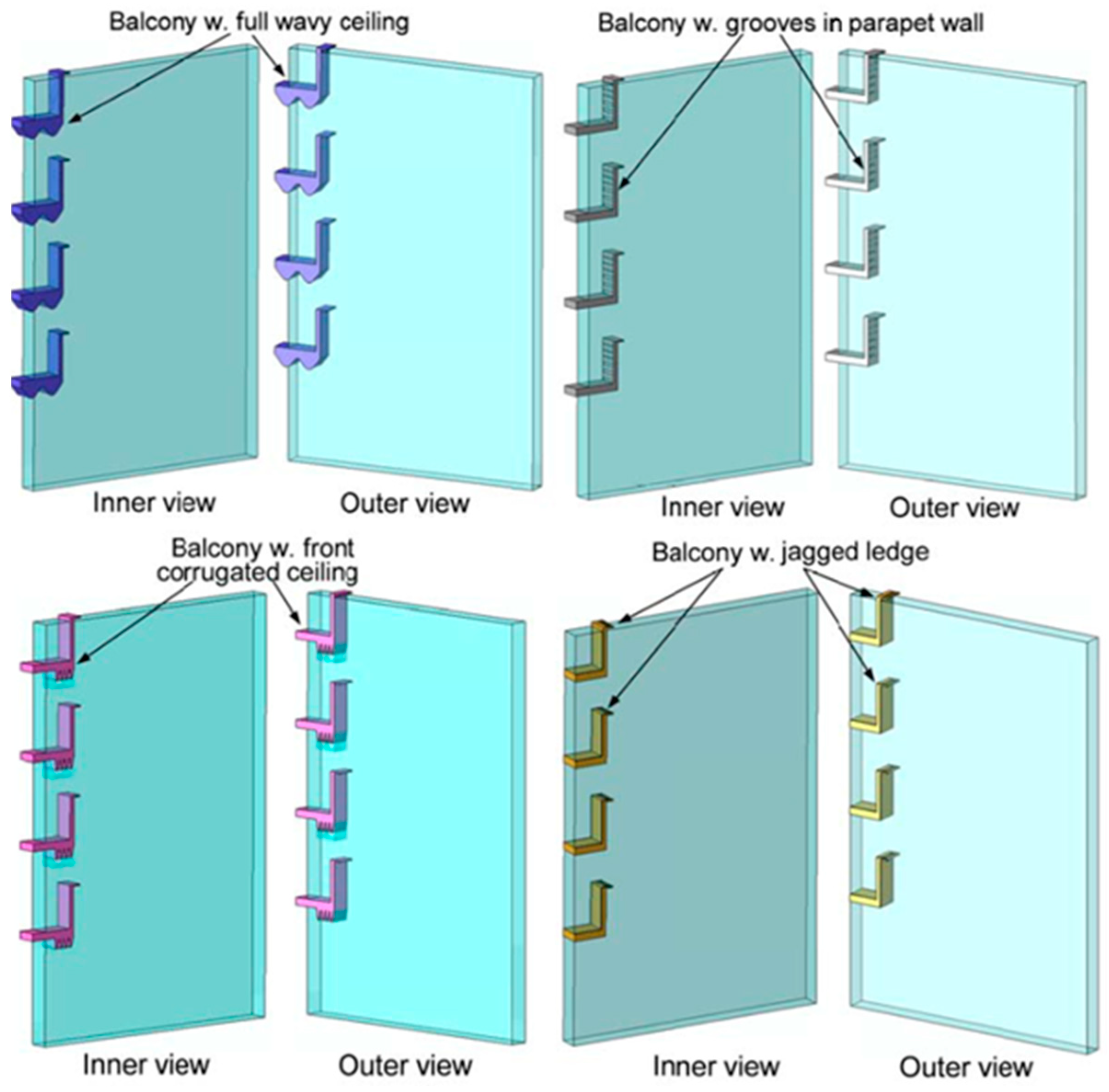
Acoustics 06 00015 i004
5Extended ledge with Jagged ceiling
Feature:
Front balcony portion having undulating ceiling
Acoustics 06 00015 i005
6Extended ledge with Full wavy ceiling
Feature:
Full undulating balcony ceiling with three crests and two troughs
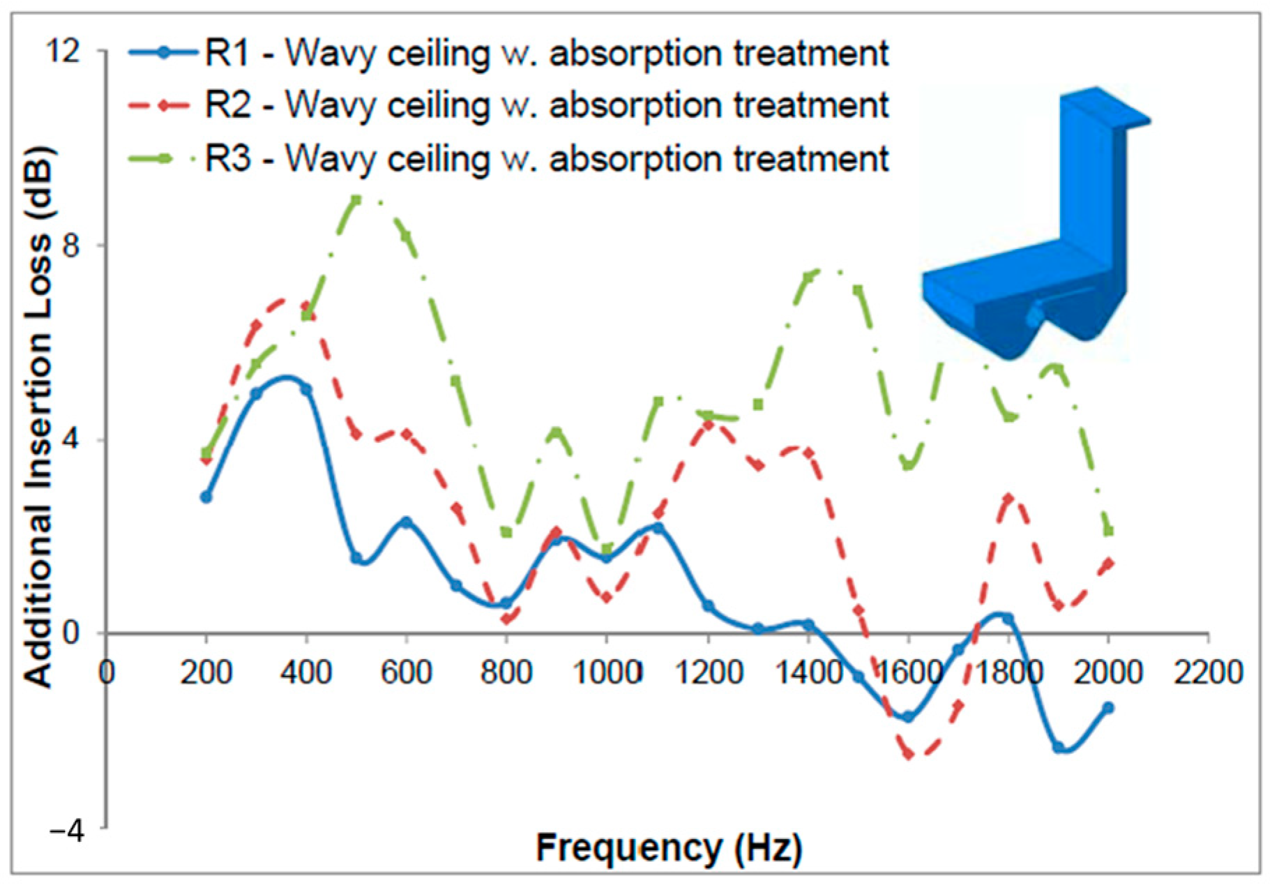
Acoustics 06 00015 i006
7Full wavy ceiling with absorption treatment
Feature:
Full undulating balcony ceiling with Helmholtz resonators
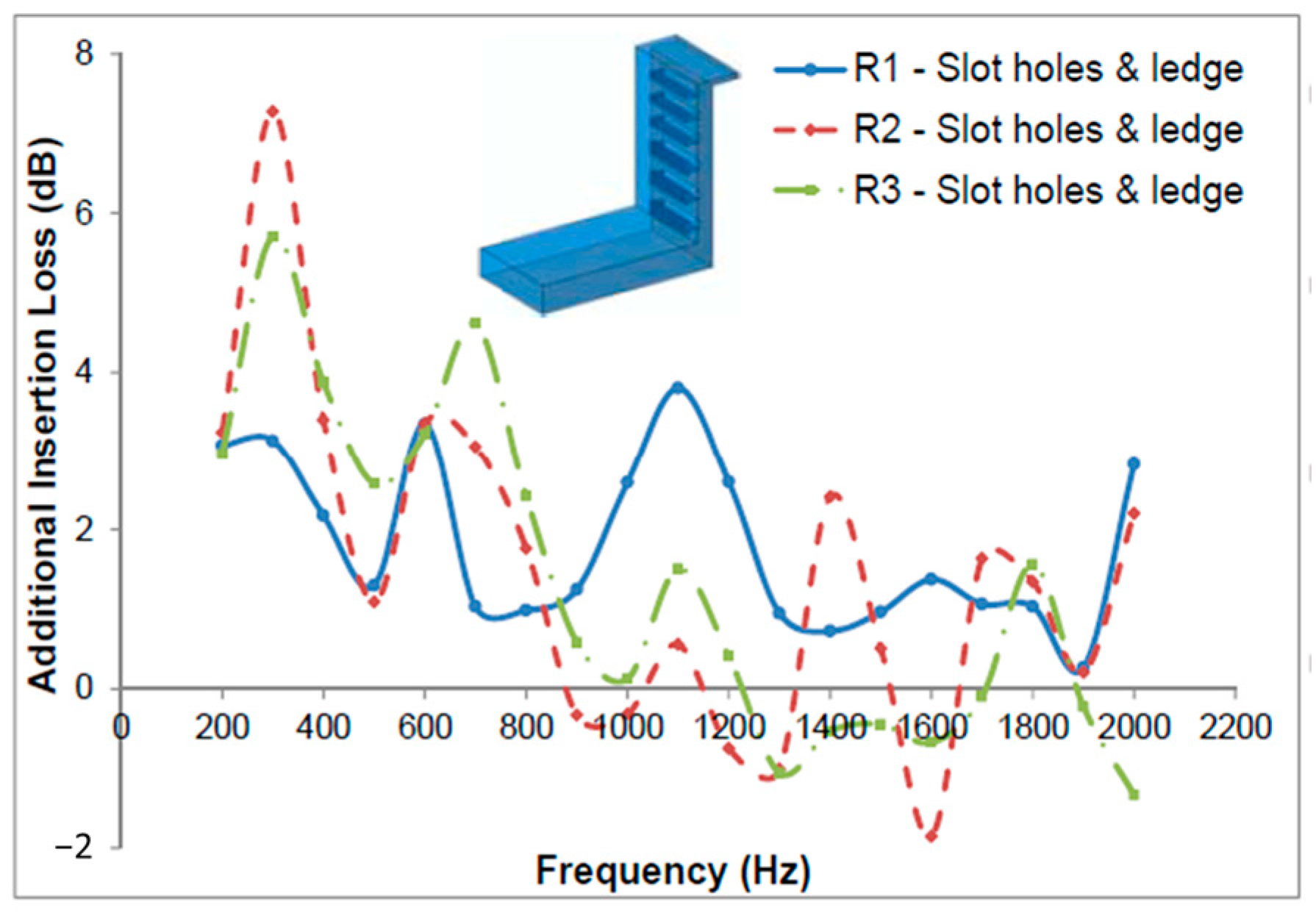
Acoustics 06 00015 i007
8Extended ledge with Corrugated front parapet
Feature:
Balcony with front parapet wall having slotted grooves
Acoustics 06 00015 i008
Table 4. Equivalent A-weighted insertion loss for R1 to R7.
DesignA-Weighted Insertion Loss (dBA)
R1R2R3Overall
Standard balcony without ledge (Case 1)9.110.47.49.1
Protruded uniform ledge (Case 2)10.7 (+1.6)11.4 (+1)6.5 (−0.9)9.7 (+0.6)
Helmholtz resonators on wall (Case 3)8.8 (−0.3)10.4 (0)7.5 (+0.1)9.6 (+0.5)
Protruded jagged ledge (Case 4)10.0 (+0.9)11.7 (+1.3)7.5 (+0.1)9.8 (+0.7)
Front jagged ceiling (Case 5)9.1 (0)11.3 (+0.9)10.2 (+2.8)10.0 (+0.9)
Full wavy ceiling (Case 6)7.3 (−1.8)11.3 (+0.9)10.7 (+3.3)9.0 (−0.1)
Treated wavy ceiling (Case 7)7.5 (−1.6)10.8 (+0.4)11.2 (+3.8)9.0 (−0.1)
Slot holes and ledge (Case 8)9.8 (+0.7)10.3 (−0.1)6.2 (−1.2)9.0 (−0.1)
Disclaimer/Publisher’s Note: The statements, opinions and data contained in all publications are solely those of the individual author(s) and contributor(s) and not of MDPI and/or the editor(s). MDPI and/or the editor(s) disclaim responsibility for any injury to people or property resulting from any ideas, methods, instructions or products referred to in the content.

