Article

Computational Prediction of New Series of Topological Ternary Compounds LaXS (X = Si, Ge, Sn) from First-Principles

by
Jack Howard
1,
Joshua Steier
2,
Neel Haldolaarachchige
3 and
Kalani Hettiarachchilage
1,*
1
Department of Physics, Seton Hall University, South Orange, NJ 07079, USA
2
Department of Applied Mathematics and Statistics, Stony Brook University, Stony Brook, NY 11790, USA
3
Department of Physical Science, Bergen Community College, Paramus, NJ 07652, USA
*
Author to whom correspondence should be addressed.
J 2021, 4(4), 577-588; https://doi.org/10.3390/j4040042
Submission received: 15 September 2021 / Revised: 23 September 2021 / Accepted: 28 September 2021 / Published: 30 September 2021
(This article belongs to the Special Issue Quantum Matter with Topological Properties)

Abstract

:
Dirac materials and their advanced physical properties are one of the most active fields of topological matter. In this paper, we present an ab initio study of electronics properties of newly designed LaXS (X = Si, Ge, Sn) tetragonal structured ternaries, with the absence and presence of spin–orbit coupling. We design the LaXS tetragonal non-symophic p4/nmm space group (no. 129) structures and identify their optimization lattice parameters. The electronic band structures display several Dirac crossings with the coexistence of both type I and type II Dirac points identified by considering the effect of spin–orbit coupling toward the linear crossing. Additionally, we perform the formation energy calculation through the density functional theory (DFT) to predict the stability of the structures and the elastic constants calculations to verify the Born mechanical stability criteria of the compounds.

1. Introduction

Adding topological insulators and topological semimetals beyond conventional insulators, metals, semimetals, and semiconductors expands quantum matter towards a new era. The nontrivial topology of electronic band structure of these distinct materials highlights exotic physical properties such as ultra-high mobility and extremely large, linear magneto-resistances [1]. Topological insulators exhibit gap-less, conducting surface states [2,3] while topological semimetals (Dirac semimetals, Weyl semimetals, and nodal line semimetals) exhibit band crossings in momentum space which are inverted beyond the crossing point (or line) [4,5,6]. In Dirac materials, linearly dispersed conduction and valence bands touch each other at single, discrete points near Fermi energy in momentum space. Those linearly dispersed band crossings are protected by topological invariants and the symmetries of the material’s crystalline space group. To describe the mass-less high mobility electrons behaviors of this unusual band dispersion require relativistic Dirac description contrasts to the usual non-relativistic Schrödinger description employed in the usual set of bulk electronic materials.
After the first discovery of Dirac band dispersion in graphene [7,8], the search for Dirac materials was extended to three-dimensional (3D) materials [9,10,11]. After experimental realization of symmetry protected 3D Dirac cones in both Cd3As2 and Na3Bi by using angle-resolved photo-electron spectroscopy (ARPES) [12,13,14,15], many different materials that host Dirac behaviors are predicted theoretically and verified experimentally. Among them Dirac semimetal behavior in Na3Bi and Cd3As2 [1,9,12,13,14,16,17,18,19,20], Weyl semimetal behavior in TaAs, TaP, NbAs [21,22,23,24,25,26,27], and nodal line semimetal behavior predicted in Cu3PdN, Ca3P2, CaP3, PbO2, CaAg, TiB2, CaAgAs, ZrB2, SrSi2 [10,28,29,30,31,32,33,34,35] and realized in PbTaSe2, PtSn4, ZrSiS, ZrSiSe, ZrSiTe, HfSiS, and ZrSnTe [27,36,37,38,39,40,41,42,43] are to name but a few examples.
By considering the slope of a linear band dispersion at the crossing point, Type I and Type II Dirac points can be identified. Type I points straighten in respect to energy with having equal and opposite slopes of the bands, while type II point tilted with having unequal slopes of the bands [44,45,46]. The concept of non-symmorphic symmetry plays an important role for identifying new types of Dirac cones as suggested by Young and Kane [47]. With the interest of searching materials belonging to non-symmorphic space groups, ZrSiS [42] was discovered and realized experimentally, and followed by ZrSiSe, ZrSiTe, HfSiS, and ZrSnTe [36,39,40,43].
In this work, a detailed study of the electronic band structures and density of states (DOS) of new ternary LaXS (X = Si, Ge, Sn) compounds belong to non-symmorphic space group is presented. To the best of our knowledge, these compounds have not yet been reported. In this paper, we report calculated electronic structures of LaXS after following carefully detailed volume optimization scheme for tetragonal structure to minimize the energy. We predict the formation of type I and type II Dirac crossings near the Fermi level. With careful investigation of electron bands and DOS features with and without inclusion of SOC effect, topological features are identified and discussed in detail. Most importantly, we identify type II Dirac crossings along Γ M plane and a few crossings belong to type I along R Γ X Z path. Three compound’s DOS and band structure with and without SOC effect are calculated and compared. Additionally, elastic constants and formation energy calculations are performed to verify the mechanical and structural stability of the new compounds.

2. Computational Method

First principal density functional theory (DFT) calculation were performed mainly using the Quantum ESPRESSO (QE) simulation package [48,49]. The plane-wave pseudo-potential method formulated with generalized gradient approximation (GGA) and the Perdew-Burke-Ernzerhof (PBE) scheme has been used with the ultra soft pseudo-potentials from PSlibrary, including fully relativistic ultra soft pseudo-potentials for spin–orbit coupling (SOC) [50,51,52,53,54,55]. We used the k-mesh of 20 × 20 × 20, kinetic energy cutoff for wave functions of 80 Ry and kinetic energy cutoff for charge density and potential of 480 Ry with checking extreme convergence of energy and charge to increase the accuracy of the simulation. Additionally, WEIN2K simulation package by using PBE pseudo-potentials and plane-wave basis set with GGA is used to compare and verify the QE results [56,57]. ElaStic software package interfaced with QE, a tool to calculate the full second order elastic stiffness tensor, has been used to calculate elastic properties [58]. The elastic tensor of second order is calculated by using the expansion of the elastic energy in terms of the applied strain and the best polynomial fits.

3. Results and Discussion

3.1. Crystal Structure

Electron configurations of La, Si, Ge, Sn and S are [Xe] 5 d 1 6 s 2 , [Ne] 3 s 2 3 p 2 , [Ar] 3 d 10 4 s 2 4 p 2 , [Kr] 4 d 10 5 s 2 5 p 2 , and [Ne] 3 s 2 3 p 4 , respectively. The La-d orbitals, X (Si, Ge, Sn)-p orbitals, and S-p orbitals are not fully occupied. The LaXS compounds are designed with tetragonal lattice structure with non-symmorphic space group symmetry of 129 (P4/nmm), by using data available for ZrSiS in Material Project [59]. The crystal structure of LaXS is consisting of S-La-X-La-S layers and held together weakly by van-der-Waals forces. There is a cleavage plane between the layers and belong to square-net materials [60]. The LaSiS structure is shown in Figure 1a. The other two structures, LaGeS and LaSnS, are the same by replacing Si with Ge and Sn, respectively. The Si, Ge, and Sn represented in blue are at top square net layer, the red La atoms are in hollow layer, and the green S atoms are in the next layer, and so on. The first Brillouin zone (BZ) of the structure shows in Figure 1b with the high symmetric points on the Brillouin zone (BZ) with Γ (0, 0, 0) point located at the center. The calculated Fermi surfaces displays in Figure 1c by indicating diamond shape interior Fermi surface with extended multiple Fermi pockets outward within the BZ. The crystal momentum in units of k = ( π / a , π / a , π / c ) is used throughout the discussion unless otherwise specified.

3.2. Volume Optimization

The volume that has the lowest total energy is identified as the ground state volume of the stable structure. Therefore, the first step is to optimize the crystals and find the volume that has the lowest total energy. In our calculations, we performed the geometry optimizations of the unit cell by using following scheme. First, the total energy has been calculated for different volumes of crystal structure by changing the lattice parameter a and by keeping the same c / a ratio. After taking the optimized volume, we calculate the total energy for different c / a ratios by keeping the same optimized volume in the above step. By varying these parameters until reaching the minimum of energy, we have performed detailed structural optimizations of the unit cell geometries as a function of the external stress and strain. The final volume optimizations graphs of LaSiS are presented in Figure 1d. Volume is calculated as V = a 2 c since the structures are tetragonal. The data points of the total energy as a function of a and c / a are plotted and fitted to third order polynomials. After following detailed optimization procedure for the LaXS, we identify the lattice parameters corresponding to the lowest energy structure as shown in Table 1. We update the unit cell parameters retaining the same atomic coordinates for all three compounds. Hence, the crystal structures at optimized bulk lattice parameters are used for further investigation of LaXS properties during the project.

3.3. Formation Energy

At thermal equilibrium, compounds that show negative formation energies with respect to its elemental phases are stable. Therefore, to study the stability of the structures, we have calculated the energy of formation for LaXS (X = Si, Ge, Sn) compounds. In general, the formation energy per atom for ternary LaXS can be calculated as
E f L a X S = E L a X S N L a E L a N X E X N S E S N L a + N X + N S = E L a X S 2 E L a 2 E X 2 E S 6 ,
where N L a , N X , and N S are the numbers of La, X (Si, Ge, Sn), and S atoms in the unit cell, respectively. Since the LaXS unit cell have two atoms of each element, N L a = N X = N S = 2 is taken. E L a X S is the calculated total free energy of the LaXS compound, and E L a , E X , and E S , are the calculated total free energies per atom of the elemental phases of La, X, and S, sequentially.
During total energy calculation of La, X, and S, we use optimized structures of hexagonal space group 194 (P63/mmc) for La, face centered space group 227 (Fd3m) for X, and monoclinic space group 13 (P2/c) for S. The calculation of formation energies of LaXS are presented in Table 1. Using these formation energies, stable and competing phases can easily be illustrated. By using Equation (1) the calculated formation energy for LaSiS, LaGeS, and LaSnS are −1.1898 eV/atom, −1.2830 eV/atom, and −1.2089 eV/atom, sequentially. Since all three compounds indicate negative formation energies with respect to its elemental phases, we identify those structures are stable.

3.4. Elastic Properties

First principles density functional calculations were applied to extensively explore the mechanical properties of the structures. The elastic constants are essential parameters that can provide valuable information about crystal stability and stiffness together with mechanical properties. The elastic stiffness matrix C i j or flexibility matrix S i j ( = [ C i j ] 1 ) is used to calculate the bulk modulus, Young’s modulus, shear modulus, and Poisson’s ratio of LaXS polycrystals by Voigt–Reuss approximation methods [58]. Average polycrystalline modules (Hill’s average) are obtained by using the upper limit and lower limit of the actual effective modulus correspond to Voigt bound and Reuss bound, which is said to be mostly agreed with the experimental result [58].
A tetragonal structure is characterized by six independent non-zero elastic constants, namely C 11 , C 12 , C 13 , C 33 , C 44 , and C 66 . The calculated elastic constants and effective bulk, shear, and Young’s modules for LaXS are given in Table 2.
The elastic constants calculated for the tetragonal crystal should satisfy the following mechanical stability criteria [61,62]:
C 11 > C 12 ; 2 C 13 2 < C 33 ( C 11 + C 12 ) C 44 > 0 ; C 66 > 0 ,
where C i j represent six independent non-zero elastic constants. The C i j results are obtained for large deformations with high-order polynomial fit by identifying the plateau regions which provides good reasonable results [58].
Calculated elastic constants for all three LaXS compounds satisfy the Born mechanical stability criteria as shown in Equation (2). Due to the negative formation energies with the fulfillment of the mechanical stability scheme, we conclude that all three compounds are mechanically and structurally stable.

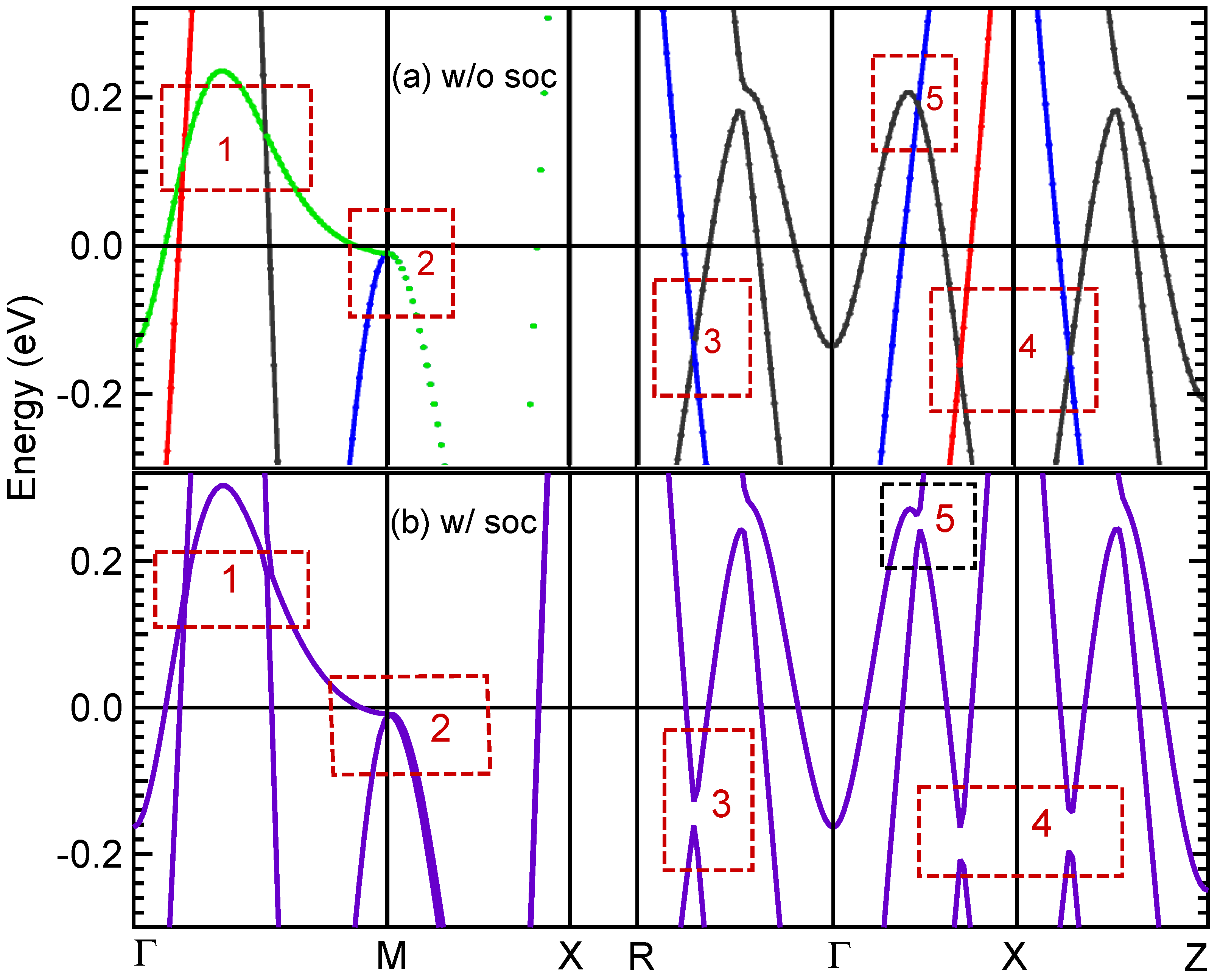
3.5. Band Structure and DOS Properties

The band structure calculations of LaSiS within GGA with and without inclusion of the SO coupling along high-symmetry k-path Γ M X R Γ X Z are plotted by setting the Fermi level at 0 eV on energy scale as shown in Figure 2. The top panel shows the band structure of LaSiS compound without inclusion of SOC effect and the bottom panel shows the compound calculated band structure with inclusion of SOC effect (purple color lines). Irreducible representation (symmorphic crystal symmetries) of band structure without SOC effect in the top panel shows band symmetries by using different colored solid lines. There are few bands near the Fermi level. Interesting band features near Fermi level are noted by using red dotted boxes, and numerated from 1 to 5. Since irreducible representation allows us to access each eigenvalues along the chosen k-path, we can identify connecting lines of bands and the symmetries by looking for the same colored bands for the same symmetry [63,64].
The two linear tilted crossings in Γ -M plane (Figure 2-bin 1), Dirac like crossing at M (Figure 2-bin 2), a single linear crossing in R Γ plane (Figure 2-bin 3), two linear crossings in Γ X and X Z planes (Figure 2-bin 4), and a single crossing in Γ X (Figure 2-bin 5) are identified. Since the SOC (some of the degenerate atomic levels split without magnetic field) have appeared as promising candidates for exotic band behaviors of Dirac materials, we perform SOC calculation to identify the topological features at the crossings. As shown in the bottom panel in Figure 2, it is clear that the crossings at bin 3, 4, and 5 are gapped out with inclusion of SO coupling. The Dirac point located at bin 3 (−0.15 eV) with the coordination of k = (0, −0.30742, 0.11663) is gapped out into two fold degeneracy. Black color represents the Γ 1 and blue color represents the Γ 5 in irreducible representations with space group C s . The blue band is identified as Si−p and black band is identified as hybridized bands of La−d and Si−p orbital by using the flat band orientations.
The two crossings located at bin 4 (left at −0.18 eV and right at −0.18 eV) are gapped out again into two fold degeneracy. At the right crossing (k = 0.30742, 0, 0.04998), black and blue bands represent the Γ 1 and Γ 5 in orderly with space group C s . At the left crossing (k = 0.30288, 0, 0), black and red colors (dominated by Si−p orbitals) represent the Γ 1 and Γ 3 , respectively, with space group C 2 v . Therefore, the crossings at around −0.15 eV and −0.18 eV are identified as type I two-fold degenerate Dirac points. These lines at crossing points display the same and opposite slopes around ±5 eV Å. These Dirac points are protected by absence of SOC with the predicted electron velocity of around 7.5 × 10 15 Å/s calculated by ( 1 / ) d E / d k , which is similar to the experimentally measured velocity of Cd3As2 [1]. The crossing in bin 5 (0.20 eV) shows two-fold degeneracy with representing black and blue symmetries as above, but there is not enough information to identify them as linear bands. The tilted crossings at bin 1 at coordinates k = (0.08783, 0.08783, 0) (left −0.11 eV) and k = (0.22568, 0.22568, 0) (right −0.17eV) are not effected by SOC and identified as Type II Dirac crossings. Here, black, red, and green colors represent the Γ 1 , Γ 3 , and the Γ 4 , respectively, in irreducible representation with space group C 2 v . The other Dirac-like crossings at the M point at energy −0.02 eV (bin 2) is protected by the non-symmorphic symmetry of the space group and not influenced by SOC effect in Figure 2b.
The results of total and partial DOS of LaSiS provide valuable information about the origin of bands with contributions from each atom and each orbital. Figure 3 display total and atom-projected DOS calculations with and without SOC effect for LaSiS. Figure 3a shows the total DOS of each atom of the LaSiS compound without SOC. Blue, red, and green represent the atom-projected DOS for La, Si, and S, respectively. The total DOS at Fermi level is around 1.8 states per eV per unit cell and dominated by Si atom DOS. Figure 3b shows the orbital projected DOS from each atom. Mostly contributed DOS at Fermi level are identified Si−p and La−d orbitals showing corresponding blue and red solid lines in Figure 3b.
The total DOS for LaSiS together with and without SOC effect display in the Figure 3c. The solid orange lines represent the total DOS with inclusion of SOC and dashed black lines represent the total DOS without SOC effect. There is no measurable differences in the total DOS near Fermi level.
We perform the band structure and DOS calculations for LaGeS and LaSnS by using the same structure as LaSiS. All the calculations are done by using the optimized lattice parameters from Table 2. Comparing the band structures for LaXS for X(=Si, Ge, Sn) in Figure 4, we conclude that all three compounds display the same band characteristics as discussed above for LaSiS. The Dirac point located at bin 3 in Figure 2 for X = Si at energy around −0.15 eV displays in Figure 4b and c at 0.08 eV for X = Ge and at 0.10 eV for X = Sn. The two crossings located at bin 4 in Figure 2 are present at energy around −0.18 eV, 0.10 eV, and 0.15 eV for LaXS (X = Si, Ge, S), respectively. The tilted left crossings at bin 1 in Figure 2 at energy around −0.11 eV for X = Si, exhibit in Figure 4b and c around 0.25 eV for X = Ge, and 0.20 eV for X = Sn. The tilted right crossings located at Figure 4-bin 1 of energy around −0.17 eV for LaSiS, display in Figure 4 around 0.10 eV for LaGeS, and −0.05 eV for LaSnS. The other Dirac-like crossings located at the M point of energy −0.02 eV (bin 2) in Figure 2 for LaSiS, change in Figure 4b and c to around −0.15 eV for LaGeS, and −0.35 eV for LaSnS. Comparing the band structures behavior with including SOC effect for LaXS with X(= Si, Ge, Sn) in Figure 4d, e and f, we identify the manifest SOC effect to three Dirac crossings located at bin 3 and 4 in Figure 2. Opening energy gaps due to SOC (ΔE) are recognized around 0.08 eV for LaSiS, 0.12 eV for LaGeS, and 0.22 eV for LaSnS as shown in Figure 4 d, e and f. The strength of SOC effect on type I Dirac points on three compounds are as follows: ΔESi < ΔEGe < ΔESn.
Comparing the total DOS for LaXS with and without inclusion of SOC for (X = Si, Ge, Sn) in Figure 5, we conclude that electrons of X element contributes mainly to the DOS of all three compounds near Fermi level. The total DOS at Fermi level display almost the same number of states per eV for all three compounds, but X = Sn shows the lowest (top panel brown dashed lines in Figure 5). The total DOS for LaXS with inclusion of SOC for X(= Si, Ge, Sn) displays in the bottom panel of Figure 5 by denoting red, blue, and brown for X = Si, Ge, and Sn accordingly. The difference between the total DOS at Fermi level with and without SOC of three compounds are 0.0225/eV for LaSiS, 0.7543/eV for LaGeS, and 0.0901/eV for LaSnS. Inset in the bottom panel of Figure 5 shows the SOC effect on DOS at Fermi level and is determined that the order of strength of SOC effect at the Fermi level is ΔDOSSi < ΔDOSSn < ΔDOSGe. The LaGeS compound shows the strongest SOC effect and we suggest further theoretical and experimental investigation of the SOC effect.

4. Conclusions

In summary, our studies of LaXS (X = Si, Ge, Sn) compounds suggest that these compounds are interesting systems to study. Dirac band behaviors near Fermi level and strong spin–orbit coupling effects can have theoretical and experimental significance on material properties, therefore further studies of LaXS are suggested. Linear band crossings near Fermi level are discovered, and type I and type II Dirac crossings are identified by investigating the SOC effect. Calculated elastic constants and formation energy predict the mechanical and structural stability of the compounds. The predicted electronic structures of LaXS, its important topological properties, and stability criteria will be useful for searching novel Dirac materials for further studies.

Author Contributions

K.H. and N.H. wrote the manuscript with the contribution from J.H. and J.S. J.H. contributes to editing, data analysis, plotting and simulation. J.H. and J.S. validate the results and contribute to data analysis and discussion. K.H. and N.H. conceptualize, supervise, validate and review the results. All authors have read and agreed to the published version of the manuscript.

Funding

N.H. acknowledges the financial support from STEMatics grant, Department of Education. N.H. and K.H. acknowledge the Extreme Science and Engineering Discovery Environment (XSEDE), supported by grant number TG-PHY190050. K.H. and J.H. acknowledge the financial support from Undergraduate Prestigious Fellowships from Seton Hall University.

Conflicts of Interest

We all certify that we have no affiliations with or involvement in any organization or entity with any financial interest or non-financial interest in the subject matter or materials discussed in this paper. The authors declare no conflict of interest.

References

  1. Liang, T.; Gibson, Q.; Ali, M.N.; Liu, M.; Cava, R.J.; Ong, N.P. Ultrahigh mobility and giant magnetoresistance in the Dirac semimetal Cd3As2. Nat. Mater. 2015, 14, 280–284. [Google Scholar] [CrossRef] [Green Version]
  2. Hasan, M.Z.; Kane, C.L. Topological insulators. Rev. Mod. Phys. 2010, 82, 3045. [Google Scholar] [CrossRef] [Green Version]
  3. Qi, X.-L.; Zhang, S.-C. Topological insulators and superconductors. Rev. Mod. Phys. 2011, 83, 1057. [Google Scholar] [CrossRef] [Green Version]
  4. Yang, B.-J.; Nagaosa, N. Classification of stable three-dimensional Dirac semimetals with nontrivial topology. Nat. Commun. 2014, 5, 4898. [Google Scholar] [CrossRef] [PubMed] [Green Version]
  5. Xu, G.; Weng, H.; Wang, Z.; Dai, X.; Fang, Z. Chern Semimetal and the Quantized Anomalous Hall Effect in HgCr2Se4. Phys. Rev. Lett. 2011, 107, 186806. [Google Scholar] [CrossRef] [PubMed] [Green Version]
  6. Zyuzin, A.A.; Wu, S.; Burkov, A.A. Weyl semimetal with broken time reversal and inversion symmetries. Phys. Rev. B 2012, 85, 165110. [Google Scholar] [CrossRef] [Green Version]
  7. Nair, R.R.; Blake, P.; Grigorenko, A.N.; Novoselov, K.S.; Booth, T.J.; Stauber, T.; NPeres, N.M.R.; Geim, A.K. Fine structure constant defines visual transparency of graphene. Science 2008, 320, 1308. [Google Scholar] [CrossRef] [Green Version]
  8. Zhang, Y.; Tan, Y.-W.; Stormer, H.L.; Kim, P. Experimental observation of the quantum Hall effect and Berry’s phase in graphene. Nature 2005, 438, 201–202. [Google Scholar] [CrossRef] [PubMed] [Green Version]
  9. Liu, Z.K.; Jiang, J.; Zhou, B.; Wang, Z.J.; Zhang, Y.; Weng, H.M.; Prabhakaran, D.; Mo, S.-K.; Peng, H.; Dudin, P.; et al. A stable three-dimensional topological Dirac semimetal Cd3As2. Nat. Mater. 2014, 13, 677–681. [Google Scholar] [CrossRef] [PubMed]
  10. Rui, Y.; Weng, H.; Fang, Z.; Dai, X.; Hu, X. Topological Node-Line Semimetal and Dirac Semimetal State in Antiperovskite Cu3PdN. Phys. Rev. Lett. 2015, 115, 036807. [Google Scholar]
  11. Young, S.M.; Zaheer, S.; Teo, J.C.Y.; Kane, C.L.; Mele, E.J.; Rappe, A.M. Dirac Semimetal in Three Dimensions. Phys. Rev. Lett. 2012, 108, 140405. [Google Scholar] [CrossRef]
  12. Liu, Z.K.; Zhou, B.; Zhang, Y.; Wang, Z.J.; Weng, H.M.; Prabhakaran, D.; Mo, S.-K.; Shen, Z.X.; Fang, Z.; Dai, X.; et al. Discovery of a Three-Dimensional Topological Dirac Semimetal, Na3Bi. Science 2014, 343, 864–867. [Google Scholar] [CrossRef] [Green Version]
  13. Neupane, M.; Xu, S.-Y.; Sankar, R.; Alidoust, N.; Bian, G.; Liu, C.; Belopolski, I.; Chang, T.-R.; Jeng, H.-T.; Lin, H.; et al. Observation of a three-dimensional topological Dirac semimetal phase in high-mobility Cd3As2. Nat. Commun. 2014, 5, 3786. [Google Scholar] [CrossRef] [Green Version]
  14. Xu, S.; Xu, S.-Y.; Liu, C.; Kushwaha, S.K.; Sankar, R.; Krizan, J.W.; Belopolski, I.; Neupane, M.; Bian, G.; Alidoust, N.; et al. Observation of Fermi arc surface states in a topological metal. Science 2015, 347, 294–298. [Google Scholar] [CrossRef] [Green Version]
  15. Borisenko, S.; Gibson, Q.; Evtushinsky, D.; Zabolotnyy, V.; Büchner, B.; Cava, R.J. Experimental Realization of a Three-Dimensional Dirac Semimetal. Phys. Rev. Lett. 2014, 113, 027603. [Google Scholar] [CrossRef] [PubMed] [Green Version]
  16. Yan, M.; Huang, H.; Zhang, K.; Wang, E.; Yao, W.; Deng, K.; Wan, G.; Zhang, H.; Arita, M.; Yang, H.; et al. Lorentz-violating type-II Dirac fermions in transition metal dichalcogenide PtTe2. Nat. Commun. 2017, 8, 257. [Google Scholar] [CrossRef]
  17. Noh, H.-J.; Jeong, J.; Cho, E.-J.; Kim, K.; Min, B.I.; Park, B.-G. Experimental Realization of Type-II Dirac Fermions in a PdTe2 Superconductor. Phys. Rev. Lett. 2017, 119, 016401. [Google Scholar] [CrossRef] [Green Version]
  18. Gibson, Q.D.; Schoop, L.M.; Muechler, L.; Xie, L.S.; Hirschberger, M.; Ong, N.P.; Car, R.; Cava, R.J. Three-dimensional Dirac semimetals: Design principles and predictions of new materials. Phys. Rev. B 2015, 91, 205128. [Google Scholar] [CrossRef] [Green Version]
  19. Schoop, L.M.; Pielnhofer, F.; Lotsch, B.V. Chemical Principles of Topological Semimetals. Chem. Mater. 2018, 30, 3155–3176. [Google Scholar] [CrossRef] [Green Version]
  20. Chang, T.-R.; Chang, T.-R.; Xu, S.-Y.; Sanchez, D.S.; Tsai, W.-F.; Huang, S.-M.; Chang, G.; Hsu, C.-H.; Bian, G.; Belopolski, I.; et al. Type-II Symmetry-Protected Topological Dirac Semimetals. Phys. Rev. Lett. 2017, 119, 026404. [Google Scholar] [CrossRef] [PubMed] [Green Version]
  21. Xu, S.-Y.; Belopolski, I.; Alidoust, N.; Neupane, M.; Bian, G.; Zhang, C.; Sankar, R.; Chang, G.; Yuan, Z.; Lee, C.-C.; et al. Discovery of a Weyl fermion semimetal and topological Fermi arcs. Science. 2015, 349, 613–617. [Google Scholar] [CrossRef] [Green Version]
  22. Lv, B.Q.; Weng, H.M.; Ma, J.Z.; Richard, P.; Huang, X.C.; Zhao, L.X.; Chen, G.F.; Matt, C.E.; Bisti, F.; Strocov, V.N.; et al. Observation of Weyl nodes in TaAs. Nat. Phys. 2015, 11, 724–727. [Google Scholar] [CrossRef]
  23. Lv, B.Q.; Gresch, D.; Wang, Z.; Wu, Q.; Troyer, M.; Dai, X.; Bernevig, B.A. Type-II Weyl semimetals. Nature 2015, 527, 495–498. [Google Scholar]
  24. Deng, K.; Wan, G.; Deng, P.; Zhang, K.; Ding, S.; Wang, E.; Yan, M.; Huang, H.; Zhang, H.; Xu, Z.; et al. Experimental observation of topological Fermi arcs in type-II Weyl semimetal MoTe2. Nat. Phys. 2016, 12, 1105–1110. [Google Scholar] [CrossRef]
  25. Xu, N.; Weng, H.M.; Lv, B.Q.; Matt, C.E.; Park, J.; Bisti, F.; Strocov, V.N.; Gawryluk, D.; Pomjakushina, E.; Conder, K.; et al. Observation of Weyl nodes and Fermi arcs in tantalum phosphide. Nat Commun. 2016, 7, 11006. [Google Scholar] [CrossRef] [PubMed] [Green Version]
  26. Yang, L.X.; Liu, Z.K.; Sun, Y.; Peng, H.; Yang, H.F.; Zhang, T.; Zhou, B.; Zhang, Y.; Guo, Y.F.; Rahn, M.; et al. Weyl semimetal phase in the non-centrosymmetric compound TaAs. Nat. Phys. 2015, 11, 728–732. [Google Scholar] [CrossRef] [Green Version]
  27. Huang, S.-M.; Xu, S.-Y.; Belopolski, I.; Lee, C.-C.; Chang, G.; Wang, B.; Alidoust, N.; Bian, G.; Neupane, M.; Zhang, C.; et al. A Weyl Fermion semimetal with surface Fermi arcs in the transition metal monopnictide TaAs class. Nat. Commun. 2015, 6, 7373. [Google Scholar] [CrossRef]
  28. Xie, L.S.; Schoop, L.M.; Seibel, E.M.; Gibson, Q.D.; Xie, W.; Cava, R.J. A new form of Ca3P2 with a ring of Dirac nodes. APL Mater. 2015, 3, 083602. [Google Scholar] [CrossRef] [Green Version]
  29. Xu, Q.; Yu, R.; Fang, Z.; Dai, X.; Weng, H. Topological nodal line semimetals in the CaP3 family of materials. Phys. Rev. B. 2017, 95, 045136. [Google Scholar] [CrossRef] [Green Version]
  30. Wang, Z.; Wang, G. A new strongly topological node-line semimetal β-PbO2. Phys. Lett. A. 2017, 381, 2856–2859. [Google Scholar] [CrossRef]
  31. Yamakage, A.; Yamakawa, Y.; Tanaka1, Y.; Okamoto1, Y. Line-Node Dirac Semimetal and Topological Insulating Phase in Noncentrosymmetric Pnictides CaAgX (X = P, As). J. Phys. Soc. Jpn. 2016, 85, 013708. [Google Scholar] [CrossRef] [Green Version]
  32. Feng, X.; Yue, C.; Song, Z.; Wu, Q.; Wen, B. Topological Dirac nodal-net fermions in AlB2 -type TiB2 and ZrB2. Phys. Rev. Mater. 2018, 2, 014202. [Google Scholar] [CrossRef] [Green Version]
  33. Hirayama, M.; Okugawa, R.; Miyake, T.; Murakami, S. Topological Dirac nodal lines and surface charges in fcc alkaline earth metals. Nat. Commun. 2017, 8, 14022. [Google Scholar] [CrossRef] [PubMed]
  34. Mikitik, G.P.; Sharlai, Y.V. Band-contact lines in the electron energy spectrum of graphite. Phys. Rev. B. 2006, 73, 235112. [Google Scholar] [CrossRef] [Green Version]
  35. Huang, H.; Liu, J.; Vanderbilt, D.; Duan, W. Topological nodal-line semimetals in alkaline-earth stannides, germanides, and silicides. Phys. Rev. B 2016, 93, 201114. [Google Scholar] [CrossRef] [Green Version]
  36. Lou, R.; Ma, J.-Z.; Xu, Q.-N.; Fu, B.-B.; Kong, L.-Y.; Shi, Y.-G.; Richard, P.; Weng, H.-M.; Fang, Z.; Sun, S.-S.; et al. Emergence of topological bands on the surface of ZrSnTe crystal. Phys. Rev. B. 2016, 93, 241104. [Google Scholar] [CrossRef] [Green Version]
  37. Wu, Y.; Wang, L.-L.; Mun, E.; Johnson, D.D.; Mou, D.; Huang, L.; Lee, Y.; Bud’ko, S.L.; Canfield, P.C.; Kaminski, A. Dirac node arcs in PtSn4. Nat. Phys. 2016, 12, 667–671. [Google Scholar] [CrossRef]
  38. Bian, G.; Chang, T.-R.; Sankar, R.; Xu, S.-Y.; Zheng, H.; Neupert, T.; Chiu, C.-K.; Huang, S.-M.; Chang, G.; Belopolski, I.; et al. Topological nodal-line fermions in spin–orbit metal PbTaSe2. Nat. Commun. 2016, 7, 10556. [Google Scholar] [CrossRef]
  39. Takane, D.; Wang, Z.; Souma, S.; Nakayama, K.; Trang, C.X.; Sato, T.; Takahashi, T.; Ando, Y. Dirac-node arc in the topological line-node semimetal HfSiS. Phys. Rev. B. 2016, 94, 121108. [Google Scholar] [CrossRef] [Green Version]
  40. Topp, A.; Lippmann, J.M.; Varykhalov, A.; Duppel, V.; Lotsch, B.V.; Ast, C.R.; Schoop, L.M. Non-symmorphic band degeneracy at the Fermi level in ZrSiTe. New J. Phys. 2016, 18, 125014. [Google Scholar] [CrossRef] [Green Version]
  41. Haubold, E.; Koepernik, K.; Efremov, D.; Khim, S.; Fedorov, A.; Kushnirenko, Y.; van den Brink, J.; Wurmehl, S.; Büchner, B.; Kim, T.K.; et al. Experimental realization of type-II Weyl state in noncentrosymmetric TaIrTe4. Phys. Rev. B 2017, 95, 241108(R). [Google Scholar] [CrossRef] [Green Version]
  42. Schoop, L.; Ali, M.N.; Straβer, C.; Topp, A.; Varykhalov, A.; Marchenko, D.; Duppel, V.; Parkin, S.S.P.; Lotsch, B.V.; Ast, C.R. Dirac cone protected by non-symmorphic symmetry and three-dimensional Dirac line node in ZrSiS. Nat. Commun. 2016, 7, 11696. [Google Scholar] [CrossRef]
  43. Hu, J.; Tang, Z.; Liu, J.; Liu, X.; Zhu, Y.; Graf, D.; Myhro, K.; Tran, S.; Lau, C.N.; Wei, J.; et al. Evidence of Topological Nodal-Line Fermions in ZrSiSe and ZrSiTe. Phys. Rev. Lett. 2016, 117, 016602. [Google Scholar] [CrossRef] [Green Version]
  44. Huang, H.; Zhou, S.; Duan, W. Type-II Dirac fermions in the PtSe2 class of transition metal dichalcogenides. Phys. Rev. B 2016, 94, 121117. [Google Scholar] [CrossRef] [Green Version]
  45. Muechler, L.; Alexandradinata, A.; Neupert, T.; Car, R. Topological Nonsymmorphic Metals from Band Inversion. Phys. Rev. X 2016, 6, 041069. [Google Scholar] [CrossRef] [Green Version]
  46. Chen, Y.; Xie, Y.; Yang, S.A.; Pan, H.; Zhang, F.; Cohen, M.L.; Zhang, S. Nanostructured Carbon Allotropes with Weyl-like Loops and Points. Nano Lett. 2015, 15, 6974–6978. [Google Scholar] [CrossRef] [Green Version]
  47. Young, S.; Kane, C.L. Dirac Semimetals in Two Dimensions. Phys. Rev. Lett. 2015, 115, 126803. [Google Scholar] [CrossRef] [Green Version]
  48. Giannozzi, P.; Baroni, S.; Bonini, N.; Calandra, M.; Car, R.; Cavazzoni, C.; Ceresoli, D.; Chiarotti, G.L.; Cococcioni, M.; Dabo, I.; et al. QUANTUM ESPRESSO: A modular and open-source software project for quantum simulations of materials. J. Phys. Condens. Matter. 2009, 21, 395502. [Google Scholar] [CrossRef] [PubMed]
  49. Giannozzi, P.; Andreussi, O.; Brumme, T.; Bunau, O.; Nardelli, M.B.; Calandra, M.; Car, R.; Cavazzoni, C.; Ceresoli, D.; Cococcioni, M.; et al. Advanced capabilities for materials modelling with Quantum ESPRESSO. J. Phys. Condens. Matter. 2017, 29, 465901. [Google Scholar] [CrossRef] [PubMed] [Green Version]
  50. Perdew, J.P.; Burke, K.; Ernzerhof, M. Generalized Gradient Approximation Made Simple. Phys. Rev. Lett. 1996, 77, 3865. [Google Scholar] [CrossRef] [PubMed] [Green Version]
  51. Singh, D.J.; Nordstrom, L. Planewaves, Pseudopotentials, and the LAPW Method, 2nd ed.; Springer: New York, NY, USA, 2006; pp. 1–134. [Google Scholar]
  52. Sjöstedt, E.; Nordström, L.; Singh, D.J. An alternative way of linearizing the augmented plane-wave method. Solid State Commun. 2000, 114, 15–20. [Google Scholar] [CrossRef]
  53. Madsen, G.K.H.; Blaha, P.; Schwarz, K.; Sjöstedt, E.; Nordström, L. Efficient linearization of the augmented plane-wave method. Phys. Rev. B 2001, 64, 195134. [Google Scholar] [CrossRef]
  54. Hohenberg, P.; Kohn, W. Inhomogeneous Electron Gas. Phys. Rev. 1964, 136, B864. [Google Scholar] [CrossRef] [Green Version]
  55. Kohn, W.; Sham, L.J. Self-Consistent Equations Including Exchange and Correlation Effects. Phys. Rev. 1965, 140, A1133. [Google Scholar] [CrossRef] [Green Version]
  56. Blaha, P.; Schwarz, K.; Sorantin, P.; Trickey, S.B. Full-potential, linearized augmented plane wave programs for crystalline systems. Commput. Phys. Commun. 1990, 59, 399–415. [Google Scholar] [CrossRef]
  57. Blaha, P.; Schwarz, K.; Tran, F.; Laskowski, R.; Madsen, G.K.H.; Marks, L.D. WIEN2k: An APW+lo program for calculating the properties of solids. J. Chem. Phys. 2020, 152, 074101. [Google Scholar] [CrossRef] [PubMed]
  58. Golesorkhtabar, R.; Pavone, P.; Spitaler, J.; Puschniga, P.; Draxl, C. ElaStic: A tool for calculating second-order elastic constants from first principles. Comp. Phys. Commun. 2013, 184, 1861–1873. [Google Scholar] [CrossRef]
  59. Jain, A.; Ong, S.P.; Hautier, G.; Chen, W.; Richards, W.D.; Dacek, S.; Cholia, S.; Gunter, D.; Skinner, D.; Ceder, G.; et al. Commentary: The Materials Project: A materials genome approach to accelerating materials innovation. APL Mater. 2013, 1, 011002. [Google Scholar] [CrossRef] [Green Version]
  60. Lee, I.; Hyun, S.I.; Shim, J.H. Topological classification of nodal-line semimetals in square-net materials. Phys. Rev. B 2021, 103, 165106. [Google Scholar] [CrossRef]
  61. Born, M. On the stability of crystal lattices. I. Math. Proc. Camb. Philos. Soc. 1940, 36, 160–172. [Google Scholar] [CrossRef]
  62. Mouhat, F.; Coudert, F.-X. Necessary and sufficient elastic stability conditions in various crystal systems. Phys. Rev. B 2014, 90, 224104. [Google Scholar] [CrossRef] [Green Version]
  63. Kittle, C. Introduction to Solid State Physics, 8th ed.; John Wiley & Sons: New York, NY, USA, 2004; pp. 1–704. [Google Scholar]
  64. Koster, G.F.; Dimmock, J.D.; Wheeler, R.G.; Statz, H. Properties of the Thirty-Two Point Groups, 1st ed.; MIT Press: Cambridge, MA, USA, 1963; pp. 1–104. [Google Scholar]
Figure 1. (Color online) Structure of bulk LaSiS. Panel (a): Crystal structure of LaSiS. The a, b, and c show the real space lattice vectors. The blue, red, and green solid spheres denote the Si, La, and S atoms, respectively. Panel (b): Bulk primitive BZ. The k x , k y , and k z show the reciprocal lattice vectors. The black dots displays the high symmetry points of the BZ with labeling Γ (0, 0, 0), M(0.5, 0.5, 0.0), X(0, 0.5, 0), R(0, 0.5, 0.5), and Z(0, 0, 0.5). Paths labeled in blue display the k-path selection for the calculations. Panel (c): Fermi surface of LaSiS bands. Panel (d): Volume optimization of LaSiS Structure. Main graph displays the volume optimization for lattice parameter a (data points represented in black solid circles and third order polynomial plot represented in red dotted lines) and the inset displays the volume optimization by choosing c / a ratio (data points represented in blue solid circles and third order polynomial fit represented in blue dotted lines).
J 04 00042 g001
Figure 2. (Color online) Calculated electronic band structure of LaSiS compound with and without SOC interaction along the high symmetry lines on the BZ k-path Γ M X R Γ X Z . (a): Irreducible representation of Calculated bulk band structure without SOC. Colors have meaning of band symmetries discussed in the text. (b): Calculated bulk band structure with SOC effect. Red dotted boxes are the topological behaviors as discussed in the text. The solid black line at zero indicates the Fermi level.
J 04 00042 g002
Figure 3. (Color online) Calculated atom-projected DOS for LaSiS without SOC and total DOS with and without SOC effect. Panel (a): Calculated DOS without SOC for La, Si, and S represented in blue, red and green, respectively. Panel (b): Calculated DOS for La( s , p and d), Si(s and p), and S(s and p) orbitals without SOC. Panel (c): Calculated total DOS for LaSiS with (black) and without (orange) SOC. The solid black vertical line at zero indicates the Fermi level.
J 04 00042 g003
Figure 4. (Color online) Calculated electronic band structures of LaXS (X = Si, Ge, Sn) with and without SOC effect. Panel (ac) represents band structures without SOC effect for LaXS compound in red (Si), blue (Ge) and brown (Sn) solid lines, respectively. Panel (df) displays the band structures with SOC effect for LaXS compounds by using the same colors lines as above. The same high symmetry k-path are used as Figure 2 to calculate band structures of LaXS. The solid black line at zero indicates the Fermi level.
J 04 00042 g004
Figure 5. (Color online) Calculated total DOS for LaXS compounds with and without SOC effect. Panel (a): Calculated DOS without SOC effect denoted by Red (X = Si), blue (X = Ge), and brown (X = Sn) for three LaXS compounds, respectively. Panel (b): Calculated DOS for LaXS with SOC effect presented in Red, blue and brown for X = (Si, Ge, Sn), sequentially. The SOC strength of three samples shows in the inset. Zero energy is set to Fermi level in all panels.
J 04 00042 g005
Table 1. The calculated lattice constants a, c, and formation energies, E of LaXS compounds.
a (Å)c (Å)E (eV/atom)
LaSiS3.78549.9782−1.1898
LaGeS3.85819.9772−1.2830
LaSnS4.054610.1559−1.2089
Table 2. The calculated elastic constants ( C i j ), bulk modulus (B), shear modulus (G), Young’s modulus (E) in units of GPa, and Poisson’s ratio ( ν ) for the LaXS compounds.
C 11 C 12 C 13 C 33 C 44 C 66 BGE ν
LaSiS139.931.439.832.821.823.945.4421.8556.500.29
LaGeS134.157.039.747.114.752.355.8224.2063.420.31
LaSnS112.378.221.463.81.090.753.6516.0043.650.36
Publisher’s Note: MDPI stays neutral with regard to jurisdictional claims in published maps and institutional affiliations.

