
Rethinking Figure-of-Merits of Liquid Crystals Shielded Coplanar Waveguide Phase Shifters at 60 GHz

Department of Electrical and Electronic Engineering, Imperial College London, London SW7 2AZ, UK
J 2021, 4(3), 444-451; https://doi.org/10.3390/j4030034
Submission received: 12 July 2021
/
Revised: 27 July 2021
/
Accepted: 10 August 2021
/
Published: 17 August 2021
(This article belongs to the Section Engineering)
Abstract
:The demand for reconfigurable millimetre-wave (mm-Wave) components based on highly anisotropic liquid crystals (LC) is higher than ever before for the UK and worldwide. In this work, 60 GHz investigation on a bespoke shielded coplanar waveguide (SCPW) phase shifter structure filled with 16 types of microwave-enabled nematic LCs respectively indicates that the patterns of the device’s figure-of-merit (FoM, defined as the ratio of maximum differential phase shift to maximum insertion loss) reshuffle from those of the characterised LC materials’ FoM (defined as the ratio of tunability to maximum dissipation factor). To be more specific, GT7-29001- and MDA-03-2838-based phase shifters exhibit the highest FoM for devices, outperforming phase shifters based on GT5-28004 and TUD-566 with the highest FoM for materials. Such a mismatch between the device’s FoM and LC’s FoM implies a nonlinearly perturbed wave-occupied volume ratio effect. Furthermore, the relationship between insertion loss and the effective delay line length is nonlinear, as evidenced by measurement results of two phase shifters (0–π and 0–2π, respectively). Such nonlinearities complicate the established FoM metrics and potentially lead to a renewed interest in the selection and material synthesis of LCs to optimise reconfigurable mmWave devices, and promote their technological exploitation in phased array systems targeting demanding applications such as inter-satellite links and satellite internet.
1. Introduction
Mobile broadband terminals [1,2,3] are becoming a prime need and rely increasingly on a continuously tunable liquid crystals (LC)-based [4,5,6,7] millimetre-wave (mmWave) beam steering flat-panel [8] antenna array, in lieu of rotating parabolic dishes [9]. The recent upsurge of high-bandwidth low-loss use cases places new demands on the selection of highly anisotropic LCs, which is as important for meeting the phase-tuning requirement as it is vital for low power dissipations in gigahertz (GHz) [10,11,12,13] and towards terahertz (THz) [14,15,16,17] regimes. Figure-of-merit (FoM) [18,19] is hence introduced to balance the above two key performance characteristics. For the past two decades of development in the field of LC-based phase shifters (variable delay lines), FoM has received a considerable level of interest as a dominant framework for the interpretation of performance, which is particularly instrumental when different research groups report their devices with diverse achievable phase-shifting ranges (at the same frequency) but intend to compare the maximum insertion loss in a fair manner.
The history and fundamental physics of LCs have well been studied [20,21]. From the electronically tunable LC material to a reconfigurable device (e.g., a phase shifter) combined with LC, without loss of generality, it is tempting to ask whether the material’s characterised FoM could directly inform the LC-based phase shifting device’s FoM. Such a research topic has neither been raised nor been answered clearly in existing literature. In the early contexts where conventional tunable materials (e.g., ferroelectrics [22,23]) are employed, various integral parameters of FoM are defined, e.g., a commutation quality factor [24]. Recent review papers on state-of-the-art microwave LC technologies [8,25] attempted to analytically link the phase shifter device’s FoM with the LC material’s FoM based on several loss-free assumptions that are impractical. The derived approximated equations have neither conveyed physical insights, nor been supported by highly resolved simulations or experimental validations. In other reviews [6,26], the authors only briefly mentioned the LC device’s FoM without involving the material’s FoM in the investigation.
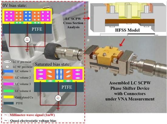
To investigate this knowledge gap, this work intends to quantify the tunable LC materials’ FoM (ratio of materials’ tunability to maximum dissipation factor) and the device’s FoM (ratio of differential phase shift to the maximum insertion loss) based on both numerical and experimental analysis performed on a state-of-the-art shielded coplanar waveguide (SCPW) [7]. The SCPW phase shifter is fabricated with nickel-free gold plating of an optimum thickness [27] (Figure 1) and edge-mounted with V connectors (1.85 mm). To probe the underlying behaviours, simulation is performed using an Ansys High-frequency Structure Simulator (HFSS, see top right of Figure 1) based on a bespoke mixed-signal quasi-analytical model (see the schematic view at the bottom left of Figure 1) that allows affordable yet reasonably reliable computation with a dielectric partitioning scheme [28] for local polarisation and tunability analysis of LC molecules interfacing the guided mmWave signals. Geometry details of Figure 1 are provided in the following section.
2. Materials and Methods
Sixteen well-established thermotropic types of microwave-engineered tunable LCs in nematic phase are evaluated in this work, with the material codes (and companies), namely, 5CB, E7, BL006, BL037, GT3-23001, GT3-24002, GT5-26001, GT5-28004, GT7-29001, TUD-566, MDA-03-2838, MDA-03-2844 (Merck KGaA, Darmstadt, Germany), CLHS-1 [6], QYPD036, QYPD142, and QYPD193 (Qingdao QY Liquid Crystal Co., Ltd., Qingdao, China). To facilitate comparison and analysis, LC material’s FoM is denoted as FoM′ and represented in Equation (1) and LC tunability is defined in Equation (2), where and denote the two extreme values of the dielectric constant at parallel and perpendicular states, respectively. Here the max. dissipation factor represents the loss tangent state with the LC molecular director biased normal to the mmWave polarisation.
FoM′ = LC tunability/max. LC dissipation factor
Comparatively, the LC-filled phase shifter’s FoM is represented by FoM″ and defined in a like manner as Equation (3) below in the degrees/decibels scale.
FoM″ = max. phase shift (°)/max. insertion loss (dB)
The geometry size of the SCPW is unified as per our experimentally optimised prototype [7], i.e., a core line width of 0.293 mm, coplanar channel (gap) width of 0.203 mm, LC layer thickness of 0.14 mm, and effective line length of 14.32 mm to produce a maximum differential phase shift of π at 60 GHz. To ensure the elimination of return loss and radiation loss due to impedance mismatching, port impedance in the simulation is intended to not necessarily be normalised to any specific impedance. In this way, the insertion loss is unambiguously related to dissipations by the materials’ absorptions only (i.e., from both dielectrics and conductors).
The cost of computational efforts for simulation analysis is economically viable by leveraging our existing experimentation knowledge with the GT3 series of LC, instead of fully probing via experiments with all 16 types of LC (the size and expenses would be non-manageable, and some of these LCs may be subject to export control protocols, even though no defence application is involved). The computer-based simulation analysis in this work is built upon our previous experimentations, which suffices to draw new insights from data, and it exhibits unique advantages, in particular as controlled experiments are infeasible to implement, with tremendous lead times and costs for the procurement of the 16 types of LCs (most of the materials are research grade and not commercially available) and the fabrication of 16 SCPW devices for measurements. Instead, parametric simulation is expandable with ease for a vast type of LCs with no additional expenses.
3. Results
LCs’ intrinsic dielectric properties (i.e., tunability, maximum dissipation factor) and hence the materials’ FoM′ were quantified for the 16 types of microwave-enabled LCs, as depicted in Figure 2 and Figure 3, respectively. Among the LCs characterised, the MDA group exhibited high tunability and moderate dissipation factors, with the overall FoM higher than the QYPD group, but less competitive than the GT series. In particular, GT5-28004 exhibited the highest material FoM′, followed by TUD-566, GT5-26001, and GT7-29001.
Comparing Figure 4 (below) against Figure 3 (below), however, patterns for the device’s FoM″ were reshuffled significantly, with GT7-29001 and MDA-03-2838 ranked at the top. The difference was attributed to the perturbed wave-occupied volume ratio of the tunable-to-non-tunable dielectrics confined in the SCPW mode, with LCs of diverse permittivity values, whereas the PTFE substrate material and SCPW geometry remained unchanged. It is interesting to note that the concept of wave-occupied-volume ratio (WoVR) was first described in our prototype [7] centred on LC-based planar devices with a non-tunable dielectric substrate. WoVR concerns the ratio of the volume taken up by the tunable medium (LC) to the total volume of dielectrics (i.e., tunable LC plus the non-tunable substrate). There are two nonlinear relationships here: first, differential phase shift versus WoVR, and second, insertion loss versus the dielectric constant ratio of tunable to non-tunable media. Future work may explore these complex interactions via machine learning (efforts underway).
It is worth noting that it is difficult for a highly integrated FoM metric to tell the physical phenomena and the effect of scale. To this end, a geometrical factor (GF) can be defined in Equation (4) and is computationally quantified in Figure 5 below. The unit for the GF here is intended to be relaxed, rendering this a relative magnitude for relevant comparisons.
GF = FoM″/FoM′
With a direct connection to WoVR, GF represents the efficiency of the specific type of LC material fitting into the device geometry. The results in Figure 5 reveal that a large part of the LCs with high material FoM′ essentially exhibited unsatisfyingly low GF (e.g., GT5-28004 and TUD-566), which limits their potential to achieve a higher device FoM″ of interest in practice.
Another insight that might have long been overlooked by existing literature is that an LC-based phase shifter’s FoM″ is not invariable concerning the line length effect. Although the achievable phase shift increases linearly with the effective line length, the insertion loss’s dependency on the effective line length is nonlinear. As a consequence, for device designs with the same cross-sectional geometry, FoM″ can vary with the line length, as evidenced in our 67 GHz experiments [29] with two LC-based phase shifter demos of the same design that differed in line length. A 0-π phase shifter with a length of L reported a maximum insertion loss of −4.37 dB, i.e., FoM″ (L) of 41.2°/dB. By upgrading the effective length to 2L and achieving a phase-shifting capability of 0–2π, the updated maximum insertion loss became −8.28 dB, i.e., FoM″ (2L) of 43.5°/dB, a 5.6% increase as compared to the FoM″ (L). This illustrates another limitation of a device’s FoM″ being a direct performance comparison metric among devices of different phase-tuning ranges. By way of illustration, a 0–π phase shifter design with a lower FoM″ (from research group 1) may not perform strictly worse than a 0–2π one (a different design by research group 2) with a higher FoM″. A more rigorous benchmarking criteria needs to adapt the FoM″ for comparing the maximum insertion loss only with the same phase-tuning range.
4. Discussion
The figure-of-merit (FoM) of LC-based phase-shifting devices is arguably the art of a unified cost–benefit ratio that replaces a set of performance parameters and facilitates benchmarking communication between the UK and global liquid crystals research. For the first time, this work reflects on a mismatching phenomenon between an LC-based phase shifter device’s FoM″ and the embedded LC material’s FoM′. By computationally analysing 16 types of mainstream mmWave-engineered LCs in a case study with an unconventional LC-based SCPW structure at 60 GHz, GT7-29001 and MDA-03-2838 exhibited the highest FoM″ for devices, surpassing those based on GT5-28004 and TUD-566 (with the highest intrinsic material FoM′). Geometrical factors were quantified and compared to explain such a discrepancy, underpinned by nonlinear wave-occupied volume effects on the phase shift as well as the line-length effect that was not linearly scalable for the insertion loss.
The constraint on existing FoM metrics could partially be remediated by incorporating the mmWave phase-tuning speed, which is remarkably limited by the fall time (FT) [12,30] of the bulk LC layer where energy is stored. An updated definition of FoM‴ can accordingly be adapted in Equation (5), catering to speed-sensitive applications, such as the emerging LC-based flat-panel antenna array for automotive radars. Factoring this into a global benchmark, optimisation insights on material synthesis could be envisioned, e.g., by balancing the polar and non-polar components [18].
FoM‴ = FoM″/FT
Albeit many open challenges remain (e.g., various nonlinear effects) for formulating a rigorously unified and reliable metric, the value of tailoring a specific FoM is still clear and remains of keen interest to LC researchers and mmWave engineers. It is advisable to keep an eye not only on the generic modalities of phase shift and insertion loss, but also on integrating more specific variables underlying the device operation, e.g., driving voltage, power handling, volume, weight, viscosity, temperature dependence, fabrication cost, and the stability of insertion loss magnitude over different driving voltages, among others. A more comprehensive performance metric can arguably enhance decision-making in navigating LCs for bespoke mmWave applications (e.g., inter-satellite links [31] and satellite internet [32]) beyond the photonics-based display sector. Though the results from this work are exclusively dedicated to LC SCPW phase shifters at 60 GHz, the implications are to a great extent transferrable to the performance evaluation of other LC-based reconfigurable mmWave devices, such as resonators, filters, etc. One of the proposed future work prospects is thus to generalise the characteristic of tunable mmWave components with FoMs of LC materials and LC devices. Another scope of research direction is about leveraging machine learning-related techniques to decipher the complex non-linearities (as discussed above) and aid in reconfigurable device design optimisation with LC materials.
Author Contributions
The author undertakes the conceptualization, modelling, simulation, experimental verification, data analysis, visualisation, manuscript writing, reviewing, and editing. The author has read and agreed to the published version of the manuscript.
Funding
This research received no external funding.
Acknowledgments
Sincere thanks to Electrical Engineering Division, Department of Engineering, the University of Cambridge, where part of the insights builds upon the author’s previous prototypes of LC SCPW phase shifters [7] developed with extensive academic training support from Daping Chu at the Centre for Photonic Devices and Sensors. Special thanks also go to Imperial College London and University of Southampton, who houses the Ansys Electronics Desktop (AEDT) and dedicated software packages for modelling and data analysis in this work.
Conflicts of Interest
The author declares no conflict of interest.
References
- Koul, S.K.; Karthikeya, G.S. Millimetre Wave Antennas for 5G Mobile Terminals and Base Stations, 1st ed.; CRC Press: Boca Raton, FL, USA, 2020. [Google Scholar]
- Attaran, M. The impact of 5G on the evolution of intelligent automation and industry digitization. J. Ambient. Intell. Humaniz. Comput. 2021, 21, 1–7. [Google Scholar]
- Maune, H.; Jost, M.; Wiens, A.; Weickhmann, C.; Reese, R.; Nikfalazar, M.; Schuster, C.; Franke, T.; Hu, W.; Nickel, M.; et al. Tunable Microwave Component Technologies for SatCom-Platforms. Frequenz 2017, 71, 129–142. [Google Scholar] [CrossRef]
- Jasiurkowska-Delaporte, M.; Kolek, Ł. Nematic Liquid Crystals. Crystals 2021, 11, 381. [Google Scholar] [CrossRef]
- Bulja, S.; Mirshekar-Syahkal, D.; Yazdanpanahi, M.; James, R.; Day, S.E.; Fernández, F.A. Liquid Crystal Based Phase Shifters in 60 GHz Band. In Proceedings of the 3rd European Wireless Technology Conference, Paris, France, 27–28 September 2010; pp. 37–40. [Google Scholar]
- Maune, H.; Jost, M.; Reese, R.; Polat, E.; Nickel, M.; Jakoby, R. Microwave Liquid Crystal Technology. Crystals 2018, 8, 355. [Google Scholar] [CrossRef] [Green Version]
- Li, J.; Chu, D. Liquid Crystal-Based Enclosed Coplanar Waveguide Phase Shifter for 54–66 GHz Applications. Crystals 2019, 9, 650. [Google Scholar] [CrossRef] [Green Version]
- Jakoby, R.; Gaebler, A.; Weickhmann, C. Microwave Liquid Crystal Enabling Technology for Electronically Steerable Antennas in SATCOM and 5G Millimeter-Wave Systems. Crystals 2020, 10, 514. [Google Scholar] [CrossRef]
- Deng, B.; Wang, H.; Qin, Y.; Zhu, S.; Li, X. Rotating parabolic-reflector antenna target in SAR data: Model, characteristics, and parameter estimation. Int. J. Antennas Propag. 2013, 2013, 1–13. [Google Scholar] [CrossRef] [Green Version]
- Jost, M.; Weickhmann, C.; Strunck, S.; Gäbler, A.; Fritzsch, C.; Karabey, O.H.; Jakoby, R. Liquid crystal based low-loss phase shifter for W-band frequencies. Electron. Lett. 2013, 49, 1460–1462. [Google Scholar] [CrossRef]
- Goelden, F.; Gaebler, A.; Goebel, M.; Manabe, A.; Mueller, S.; Jakoby, R. Tunable liquid crystal phase shifter for microwave frequencies. Electron. Lett. 2009, 45, 686–687. [Google Scholar] [CrossRef]
- Nova, V.; Bachiller, C.; Villacampa, B.; Kronberger, R.; Boria, V.E. Characterization of Nematic Liquid Crystals at Microwave Frequencies. Crystals 2020, 10, 1106. [Google Scholar] [CrossRef]
- Tesmer, H.; Razzouk, R.; Polat, E.; Wang, D.; Jakoby, R.; Maune, H. Temperature Characterization of Liquid Crystal Dielectric Image Line Phase Shifter for Millimeter-Wave Applications. Crystals 2021, 11, 63. [Google Scholar] [CrossRef]
- Bui, V.B.; Inoue, Y.; Moritake, H. NRD waveguide-type terahertz phase shifter using nematic liquid crystal. Jpn. J. Appl. Phys. 2019, 58, 022001. [Google Scholar] [CrossRef]
- Yang, C.S.; Kuo, C.; Chen, P.H.; Wu, W.T.; Pan, R.P.; Yu, P.; Pan, C.L. High-Transmittance 2π Electrically Tunable Terahertz Phase Shifter with CMOS-Compatible Driving Voltage Enabled by Liquid Crystals. Appl. Sci. 2019, 9, 271. [Google Scholar] [CrossRef]
- Ito, R.; Kumagai, T.; Yoshida, H.; Takeya, K.; Ozaki, M.; Tonouch, M.; Nose, T. THz Nematic Liquid Crystal Devices Using Stacked Membrane Film Layers. Mol. Cryst. Liq. Cryst. 2011, 543, 77–843. [Google Scholar] [CrossRef]
- Fuscaldo, W.; Tofani, S.; Zografopoulos, D.C.; Baccarelli, P.; Burghignoli, P.; Beccherelli, R.; Galli, A. Tunable Fabry-Perot cavity THz antenna based on leaky-wave propagation in nematic liquid crystals. IEEE Antennas Wirel. Propag. Lett. 2017, 16, 2046–2049. [Google Scholar] [CrossRef]
- Belyaev, V.; Chigrinov, V. Figure of merit of liquid-crystal materials for optically addressed spatial modulators. Appl. Opt. 1993, 32, 141–146. [Google Scholar] [CrossRef]
- Cai, L.; Xu, H.; Li, J.; Chu, D. High Figure-of-merit compact phase shifters based on liquid crystal material for 1–10 GHz applications. Jpn. J. Appl. Phys. 2017, 56, 011701. [Google Scholar] [CrossRef]
- Dierking, I. Textures of Liquid Crystals; Wiley-VCH: Weinheim, Germany, 2003. [Google Scholar]
- Dierking, I. Handbook of liquid crystals. Liq. Cryst. Today 2015, 24, 25–27. [Google Scholar] [CrossRef]
- Tagantsev, A.; Sherman, V.; Astafiev, K.; Venkatesh, J.; Setter, N. Ferroelectric Materials for Microwave Tunable Applications. J. Electroceramics 2003, 11, 5–66. [Google Scholar] [CrossRef]
- Auciello, O.; Saha, S.; Kaufman, D.; Streiffer, S.; Fan, W.; Kabius, B.; Im, J.; Baumann, P. Science and technology of high dielectric constant thin films and materials integration for application to high frequency devices. J. Electroceramics 2004, 12, 119–131. [Google Scholar] [CrossRef]
- Vendik, I.B.; Vendik, O.G.; Kollberg, E.L. Commutation quality factor of two-state switchable devices. IEEE Trans. Microw. Theory Tech. 2000, 48, 802–808. [Google Scholar] [CrossRef]
- Zografopoulos, D.C.; Ferraro, A.; Beccherelli, R. Liquid-crystal high-frequency microwave technology: Materials and Characterization. Adv. Mater. Technol. 2019, 4, 1800447. [Google Scholar] [CrossRef]
- Ting, T. Technology of liquid crystal based antenna. Opt. Express 2019, 27, 17138–17153. [Google Scholar] [CrossRef]
- Li, J. 60 GHz optimised nickel-free gold-plated enclosed coplanar waveguide liquid crystal phase shifter. In Proceedings of the 2020 IEEE MTT-S International Microwave Workshop Series on Advanced Materials and Processes for RF and THz Applications, Suzhou, China, 29–31 July 2020; pp. 1–3. [Google Scholar]
- Li, J. An efficient mixed-signal dielectric-partitioning model of liquid crystals based shielded coplanar waveguide for electronically reconfigurable delay lines design. Proc. SPIE 2021, 11775, 1177519. [Google Scholar]
- Li, J. Millimetre-wave beam steering with analog-resolution and minimised distortion based on liquid crystals tunable delay lines with enhanced signal-to-noise ratios. Proc. SPIE 2020, 11541, 115410H. [Google Scholar]
- Garbovskiy, Y.; Zagorodnii, V.; Krivosik, P.; Lovejoy, J.; Camley, R.E.; Celinski1, Z.; Glushchenko, A.; Dziaduszek, J.; Dąbrowski, R. Liquid crystal phase shifters at millimetre wave frequencies. J. Appl. Phys. 2012, 111, 054504. [Google Scholar] [CrossRef]
- Tebbe, M.; Hoehn, A.; Nathrath, N.; Weickhmann, C. Manufacturing and testing of liquid crystal phase shifters for an electronically steerable array. In Proceedings of the 2017 IEEE Aerospace Conference, Big Sky, MT, USA, 4–11 March 2017; pp. 1–12. [Google Scholar]
- Wittek, M.; Fritzsch, C.; Schroth, D. Employing Liquid Crystal-Based Smart Antennas for Satellite and Terrestrial Communication. Inf. Disp. 2021, 37, 17–22. [Google Scholar]
Figure 1.
Modelled and fabricated prototype of an LC-based SCPW phase shifter device for 60 GHz.

Figure 2.
Various LCs’ dielectric properties characterised for 60 GHz.

Figure 3.
Various LC materials’ FoM′ at 60 GHz (results derived from Figure 2).
Figure 3.
Various LC materials’ FoM′ at 60 GHz (results derived from Figure 2).

Figure 4.
Devices’ FoM″ with different LCs at 60 GHz (simulated with HFSS).


Publisher’s Note: MDPI stays neutral with regard to jurisdictional claims in published maps and institutional affiliations. |
© 2021 by the author. Licensee MDPI, Basel, Switzerland. This article is an open access article distributed under the terms and conditions of the Creative Commons Attribution (CC BY) license (https://creativecommons.org/licenses/by/4.0/).
Share and Cite
MDPI and ACS Style
Li, J. Rethinking Figure-of-Merits of Liquid Crystals Shielded Coplanar Waveguide Phase Shifters at 60 GHz. J 2021, 4, 444-451. https://doi.org/10.3390/j4030034
AMA Style
Li J. Rethinking Figure-of-Merits of Liquid Crystals Shielded Coplanar Waveguide Phase Shifters at 60 GHz. J. 2021; 4(3):444-451. https://doi.org/10.3390/j4030034
Chicago/Turabian StyleLi, Jinfeng. 2021. "Rethinking Figure-of-Merits of Liquid Crystals Shielded Coplanar Waveguide Phase Shifters at 60 GHz" J 4, no. 3: 444-451. https://doi.org/10.3390/j4030034