1. Introduction
Nowadays, the drift in the energy world is directed toward flexibility, portability, high capability, multifunctionality, and scale reduction in the development of power generators [
1,
2,
3,
4]. Power generation can be defined as a collection of energy from surrounding environments in the form of Vivo energies, light, or radio waves to be converted into and stored as electric power. The common resources are fluid flows, heat, and mechanical vibrations/stress. This energy can be supplied to different types of devices, such as biomedical devices, mobile electronic devices, and wireless sensor devices. However, electrochemical batteries are the main power source for these devices. The disadvantages of such power sources are the limited lifetime of batteries and the replacement process. On the other hand, there is a difference in the power level that is produced by clean energy generators and other power generation ideologies [
5]. Accordingly, the need for advanced energy generation technology, such as wireless power transmission and self-power devices, has increased [
6,
7,
8,
9].
Energy harvesting became the alternative application of batteries as an electric power source [
10,
11]. Human movement and activities, transportation means, and industrial equipment are examples of energy sources that can be converted to electric power. Unlike conventional batteries, these energy sources allow operation in different environmental conditions. Furthermore, there have been several approaches proposed to harvest energy, such as electromagnetic, triboelectric, electrostatic, piezoelectric, and different transduction mechanisms, at different scales [
12]. Piezoelectric generators utilize active materials to convert mechanical pressure or stress into electric power. However, the other approaches would utilize capacitance, electrostatic induction, heat, or frictional contact to generate electric power.
Piezoelectricity is an area that has sparked research in various fields due to its nature in obtaining efficient energy. This is because of how mechanical pressure generates energy that can be converted to valuable electric power [
10,
13,
14,
15,
16,
17]. It uses specific materials with a crystalline molecular formation, quartz, tourmaline, and Rochelle salt to effectively generate a voltage along the surface of these crystals. A separate voltage source, material contact, or magnetic field are not required for piezoelectric due to its essential polarization, unlike triboelectric, electromagnetic, and electrostatic [
18,
19]. Therefore, piezoelectric is more reliable than other renewable energy generators [
20,
21,
22,
23,
24,
25]. For example, piezoelectric is capable of converting different types of mechanical energy to power electricity [
22]. In addition, piezoelectric is capable of generating more energy compared to triboelectric with the same size [
21]. Piezoelectric can be compacted and integrated into microdevices. Furthermore, it is resistant to the environment; it is not affected by temperature [
1,
26,
27] with certain exceptions, such as biodegradable piezoelectric material; for example, PLLA shows low stability in a high-temperature environment. It has been demonstrated, however, that piezoelectric technology is suitable for a wide range of applications and has shown promising results in most instances [
26].
Composites, ceramics, bio-inspired materials, polymers, and crystals are piezoelectric resources that are used to design piezoelectric harvesters with different scales and layer stacks. The application most affected by the improvement of piezoelectric technology is the wireless sensor system. The need for a sustainable power supply to these systems has increased as the number of distributed sensors within arranged fields has increased. Thus, the power requirement is a highly continuous demand. The latent field of applications for this technology is environmental monitoring, infrastructure, transportation, industry, and healthcare. Through piezoelectric energy generators, it became possible to monitor tire pressure wirelessly via sensor devices [
28,
29].
On the other hand, the power grid nowadays relies heavily on fossil fuels, which are harmful to the environment, and is seeing its supplies diminish at a high rate. According to the US Energy Information Administration, fossil fuels accounted for 62.7% of the electricity generated in the United States in 2019 [
30]. To alleviate the pressure on the limited fossil fuel resources, we planned to innovate and research new “clean” energy sources. That way, when the reserves deplete, technologies capable of harvesting this energy are well developed and can substitute it as a new primary energy source.
In brief, the focus of this paper is to tickle more into the “piezoelectric effect” and integrate it with Qi-standard wireless transmission to design a reliable wireless charging system. Our plan is to pair piezoelectric technology with Bluetooth Low Energy (BLE) to find a green way to generate and store power wirelessly for later use. BLE is a form of communication that allows for the short-range transfer of data using low power compared to traditional Bluetooth technologies [
31]. For this reason, BLE is being implemented in numerous Internet of Things devices. We believe that utilizing piezoelectricity and wireless transmission would lead to a technology that provides useful information and data that can be observed throughout the system.
This paper is organized as follows: the state-of-the-art background is discussed in
Section 2.
Section 3 presents the proposed system architecture, design process, and implementation, and the results. The work is concluded in
Section 4.
3. Proposed System
Unlike existing designs, our goal is to achieve a fully working piezoelectric wireless charger, which current chargers do not have the capacity to perform. While wireless chargers are a prevalent technology, the addition of piezoelectric technology is a relatively unexplored field [
45]. For this reason, harnessing piezoelectricity for wireless charging would prove to be innovative. Another original concept for this design is that it utilizes a custom-built application for providing the user with important system data.
The main problem we have encountered with piezoelectricity is the difficulty of generating electrical current simultaneously. The needs will be met by implementing a wireless charging solution using stored electricity that is generated from piezoelectric materials. This solution will adhere to Qi standards to be widely compatible with many devices. These piezoelectric harvesters will generate electricity through the user’s mechanical energy. The harvester will be connected to a storage system, which will be a wireless charger capable of recharging a user’s handheld devices. This paper will demonstrate that piezoelectric wireless chargers hold massive potential through their scalability. Piezoelectric transducers are quite small; they are typically about one inch in diameter. Their small size allows them to be configured to apply to different systems such as shoes, wheelchairs, and more. With piezoelectricity, users can generate electricity that can be harnessed for their electronic devices efficiently and wirelessly. Wireless charging also introduces a convenience factor that eliminates the need for obstructive wires that can get in the user’s way while causing discomfort. Additionally, it allows a convenient way to charge a user’s device quickly and easily without taking the time to plug in the device or being restricted by wires.
This paper seeks to provide a clean generation approach paired with a method for wirelessly charging devices. Since electricity will be harvested from mechanical stresses such as vibration, it provides a greener way of generating electricity. In today’s world, where most of our power generation comes from non-renewable sources, it is a welcome sight to see new green power being generated. Since the concept is made with portability in mind, it has the capability of being worn or used by any operator on the go. Place the apparatus in gloves, on shoes, or along a wheelchair. Daily movements, such as those associated with walking or rolling, will be capable of generating electricity. As a result, it will also empower people to be more active in their daily lives because there is an additional incentive than just having a healthy lifestyle. It will be very convenient when charging your devices as you will not have to search for a charger wire and deal with its unreliability.
3.1. Hardware Design Setup
The system architecture is modular, consisting of four main subsystems: full-wave-rectified piezoelectric generation, battery storage, Qi-standard wireless transmission, BLE, and a monitoring app; three of which have extensive hardware infrastructure. The piezoelectric generation circuit was first designed using simulation software such as MATLAB/Simulink. This allowed for testing our design and making necessary changes before purchasing components. The hardware of this subsystem consists of a piezoelectric element that will generate electricity from mechanical stress. The generated electricity is then converted into DC using full-wave bridge rectifiers to be stored in battery cells. Here is where a voltage sensor will transmit the voltage data to the application via BLE, where it will be displayed along with other information on the application for the user. Then, the stored electricity will be transferred by a Qi-standard wireless transmitter to be able to charge devices. Qi standards ensure that our system allows for maximum compatibility.
3.2. Software Setup
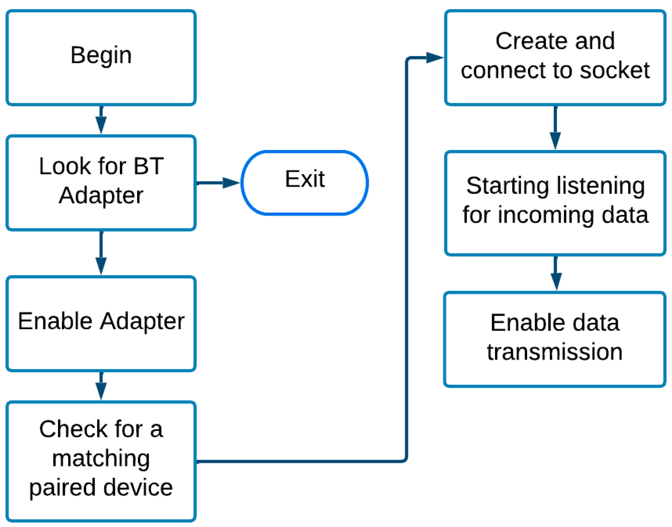
Android Studio provides an excellent environment for creating applications. Using Android Studio, we were able to take advantage of a user interface that allows you to see changes to the application in real time. Additionally, an emulator feature allows building and installing your application on a simulated Android environment. API levels are another important parameter when programming an application because restrictions can occur when utilizing features in applications, such as Bluetooth Low Energy. Bluetooth Low Energy (BLE) implements several Java functions, which work by performing the following procedure (see
Appendix A,
Figure A1).
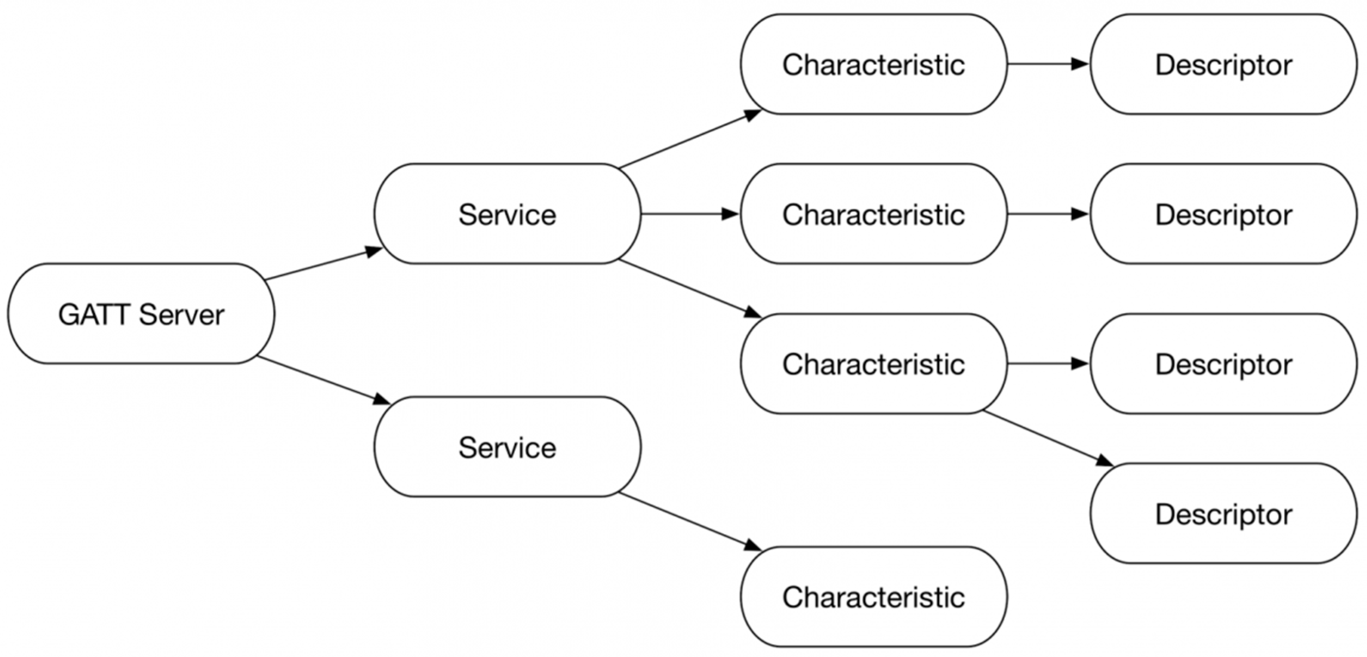
BLE enabled us to transfer data from the design piezoelectric generator to our application so that the user remains updated about the devices’ status. For the application to obtain data from the hardware subsystems, it must have a BLE server to which it can connect. The server connection parameters and services were all defined in the PSoC Creator app, which is then programmed into the chip. The Cypress BLE chip then acted as a gateway for communication between the hardware and the application. The Cypress BLE chip organized a server consisting of a GATT server. The GATT server contains a hierarchical data organization, as shown in
Appendix A,
Figure A2.
The services contain a set of different data types, each characteristic having an actual data value, and the descriptor describes the data type, such as percentage, voltage, current, etc. The characteristics include a voltage signal read and sent to the BLE chip’s built-in analog-to-digital converter. This converts the voltage data into a readable value by the system. To implement this, several requirements must be completed for BLE to work with the application. These requirements will be discussed in the next section.
3.3. Materials and Methods
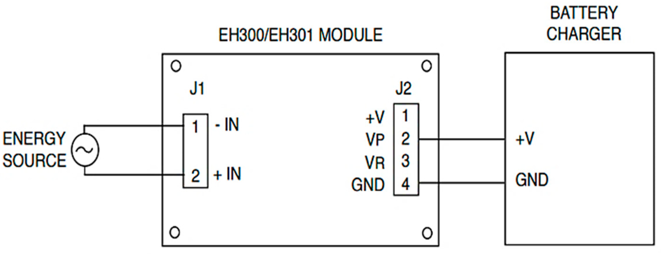
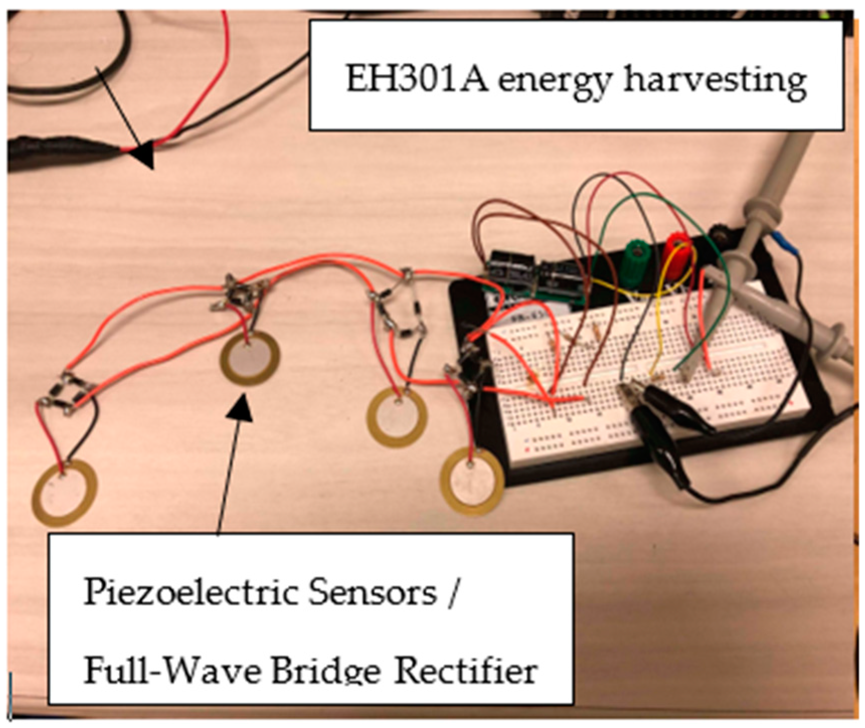
For the hardware, due to the AC output of a piezoelectric transducer, we rectified it with the 1N4001 Schottky diodes to obtain a DC signal. Each transducer must be rectified before each branch could be hooked up in parallel to avoid deconstructive interference between them. The generation subsystem interfaced with the storage subsystem, where the charging operation occurred. This was performed via a charge bursting operation. Based on our research, we chose an energy harvesting module, specifically the EH301A. Theoretically, this module stores up to 55 mJ of energy from various types of electrical sources, which can be used to power conventional 3.3 V and 5.0 V devices. We used full-wave-rectified piezoelectric devices configured parallelly for our source of electrical energy. Below,
Figure 1 shows how the EH301A will be used to charge the batteries (batteries were used as storage to test our design).
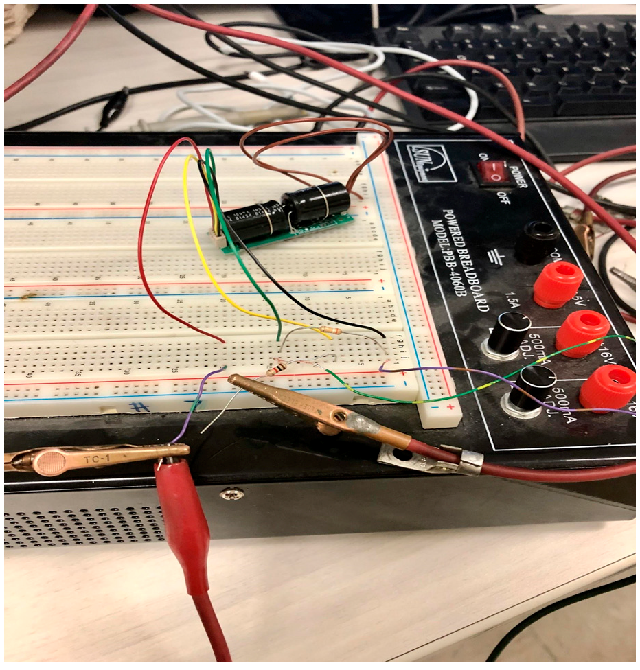
Figure 2 shows the functionality being tested.
This testing revealed that the EH301A energy harvester had an issue charging up to the triggering value VH = 5.2 V when tested with a single piezoelectric transducer. Despite the fact that this issue could be solved with our multiple parallel configurations, the module charged slower as the stored energy in it increased. The issue would easily be resolved, given the fact the finished system has many more piezoelectric sources. This would have been implemented either by tuning a high-resistance voltage divider between +V, VP, and GND or through a software trigger of the Cypress module. By using this module to capture the small amounts of electrical power generated by stressing the piezoelectric elements, AA battery cells will be charged in parallel and hooked up in a series configuration. Special switching circuitry was installed to ensure the device worked as intended. A power converter was necessary to energize the Qi-transmitter, which requires 1–2 A at a steady 5 V.
Applying Equation (1) allowed us to define the power input and output relationships of the internal subsystems:
The power converter must output 5–10 W. Since each AA battery has a nominal voltage of 1.3 V, four of these in series yield 5.2 V. Equation (2) shows the relationship between power, voltage, and current:
Since we desire maximal power generation, Equation (2) also helped us conduct our short-circuit analysis. This means 0.962–1.923 A must be drawn into the power converter, assuming 100% efficiency, which is not the case. Power factor is the relationship between Pin and Pout, and Equation (3) is:
Split between two branches of four AA batteries, each branch must contribute 0.481–0.962 A. Given the AA batteries have a capacity of 2800 mAh, it is clear that the current drawn by the power converter is capable of being supplied by the AA batteries.
To approximate the DC output that results from the cycling of the EH301A, Equation (4):
The value “
” can be computed using Equation (5):
where “D” represents the duty ratio, and “T” represents the cycling period. Equation (6) notes the relationship between energy (J), voltage, and electric charge (mAh):
The Qi wireless transmitter transfers power to another object through resonant inductive coupling. A changing magnetic flux is established by rapidly changing the current running through the transmitter coil. This magnetic flux links with the receiver’s coil, resulting in a current and net power transfer. To change the current running through the transmitter, MOSFET switching technology is utilized. This technology brings a theoretical power factor of 0.5, meaning less than half of the sent power is received. Even with this power loss, wireless power transmission remains a desired commodity.
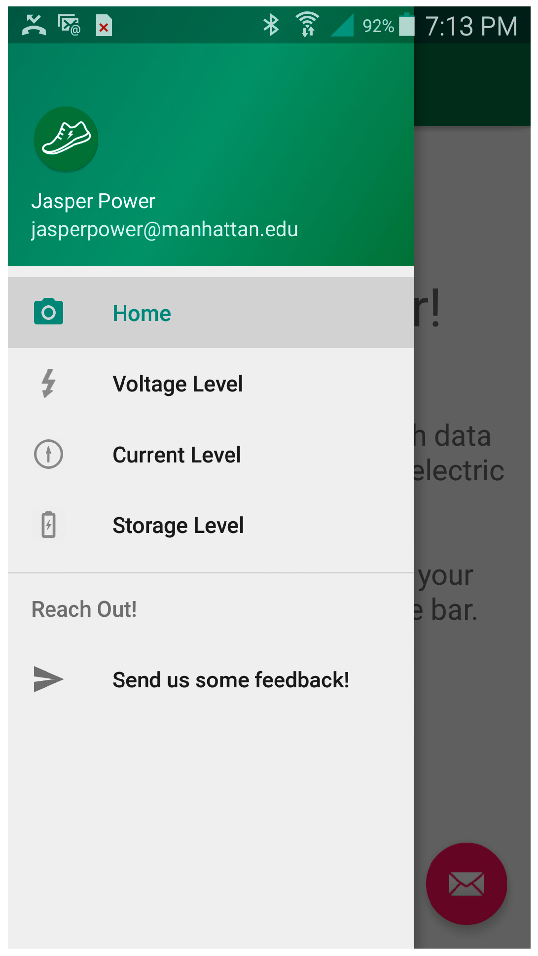
For the software, we decided that the best way to display and transfer voltage data from the hardware component was by creating an application using Android Studio in Java. We named the application “Jasper Power” and developed a Jasper green theme for the user interface.
For our application to transfer data from the hardware, we needed to program the application to communicate with a Cypress BLE chip. So, we set up the BLE chip by implementing a GATT profile and its characteristics, such as the voltage of our hardware subsystems. Furthermore, we set up parameters such as advertising and scanning times so the application could discover the BLE chip. Once the BLE chip is paired, data transfer is initiated.
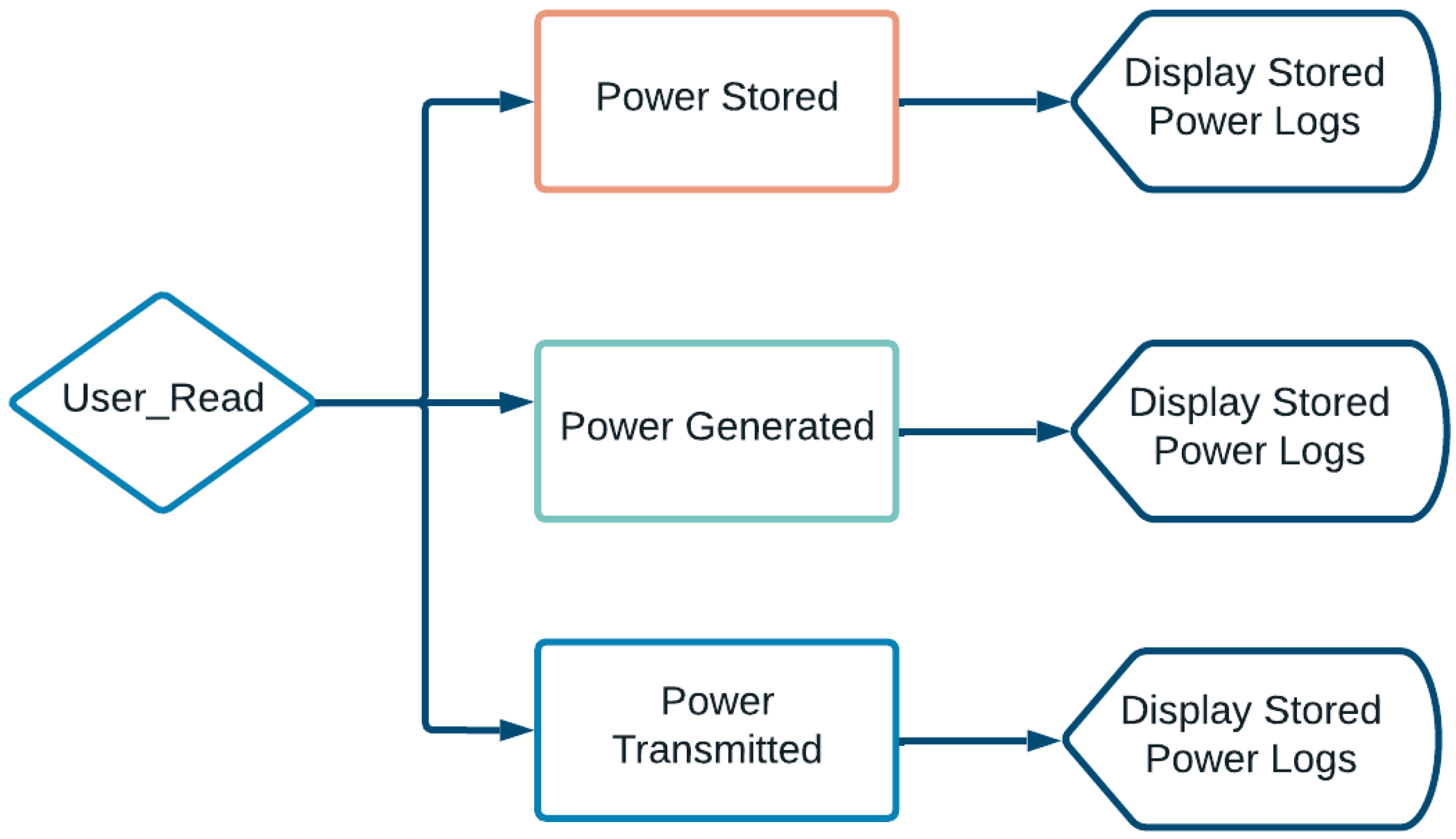
Figure 3 illustrates how a user can access logs of the power generated, the power stored, and the power transmitted using an app on their phone.
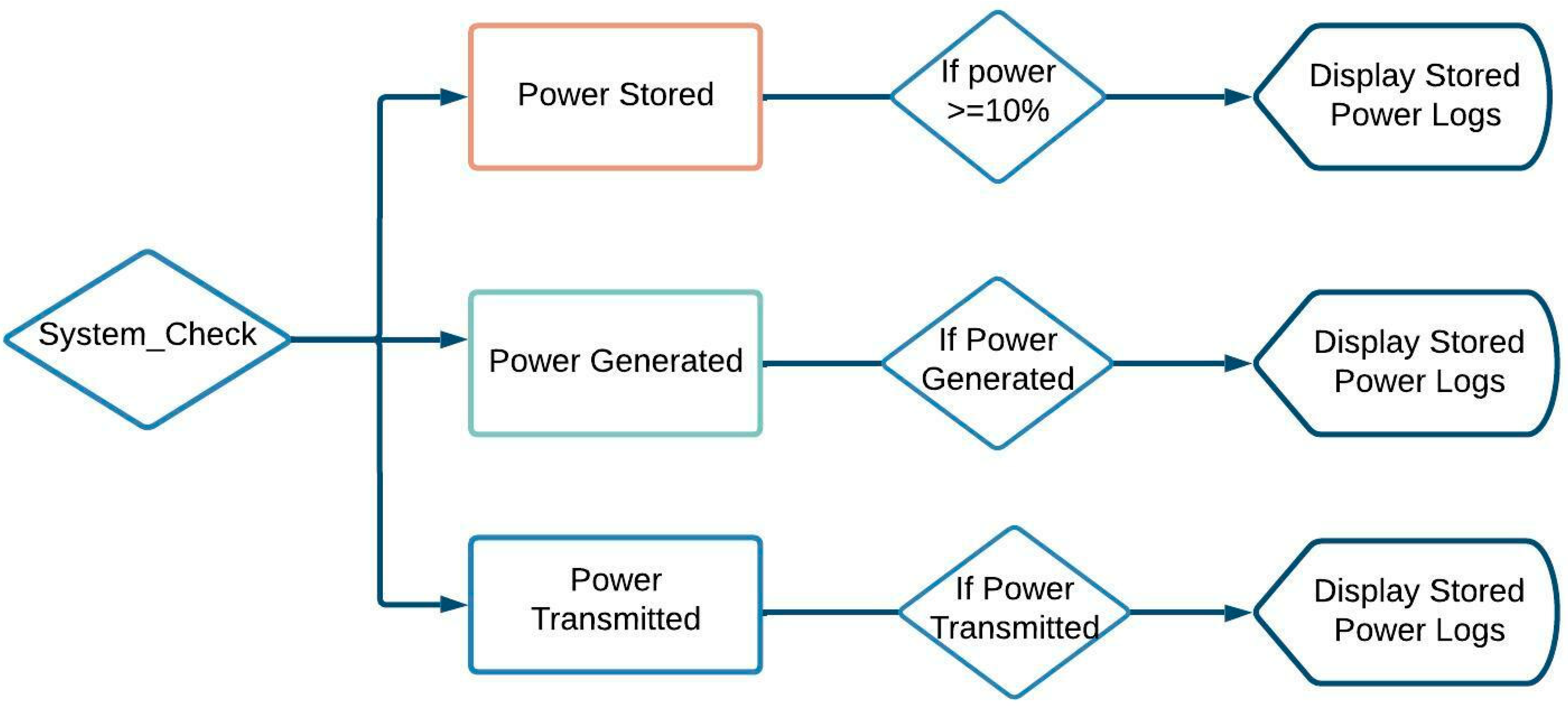
Figure 4 shows how the program will check if enough generated energy has been stored, and if so, an L.E.D. will turn on, indicating it is ready to charge a device. An indication L.E.D. will also turn on if a device is being charged.
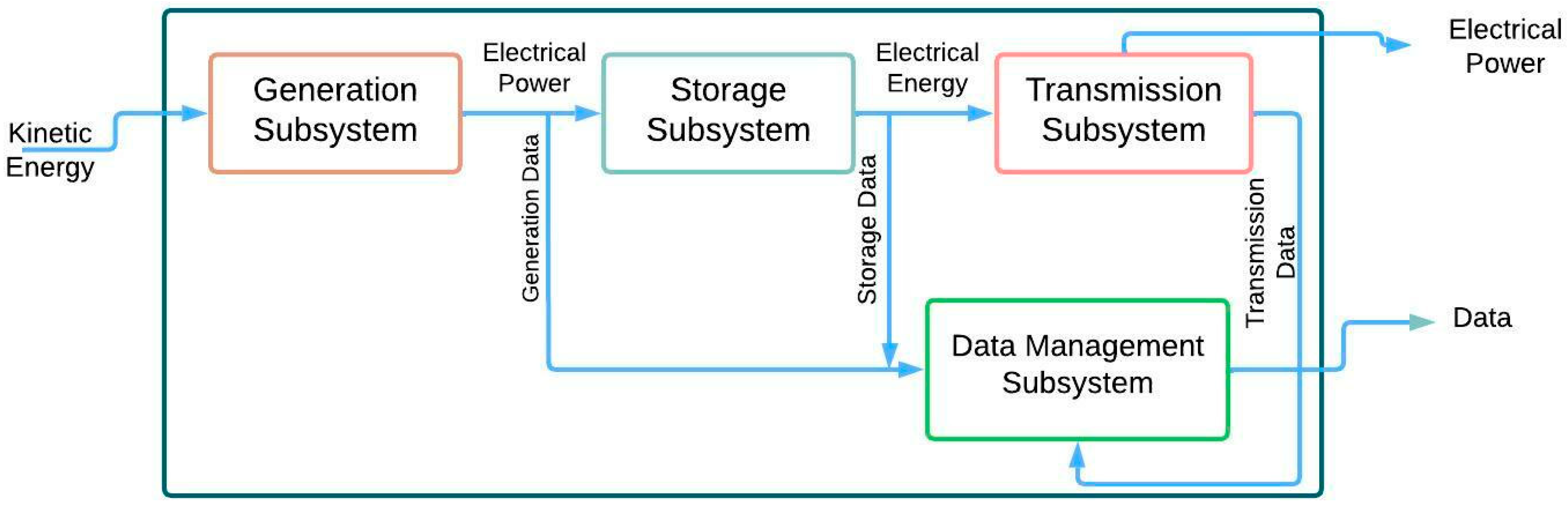
3.4. System Architecture
Figure 5 illustrates the overview system that includes the main components: full-wave-rectified piezoelectric generation, battery storage, Qi-standard wireless transmission, and the BLE. Respectively, they are the generation, storage, transmission, and data subsystems. The involved processes consist of piezoelectric elements that generate AC electricity from mechanical stress. The generated electricity is then converted into DC using full-wave bridge rectifiers to be stored in battery cells. Here is where a voltage sensor will transmit the voltage data to the software application via BLE, which will be displayed along with other information on the application for the user. Then, the stored electricity will be transferred by a Qi-standard wireless transmitter to charge devices. Qi standards ensure that our system allows for maximum compatibility for user performance.
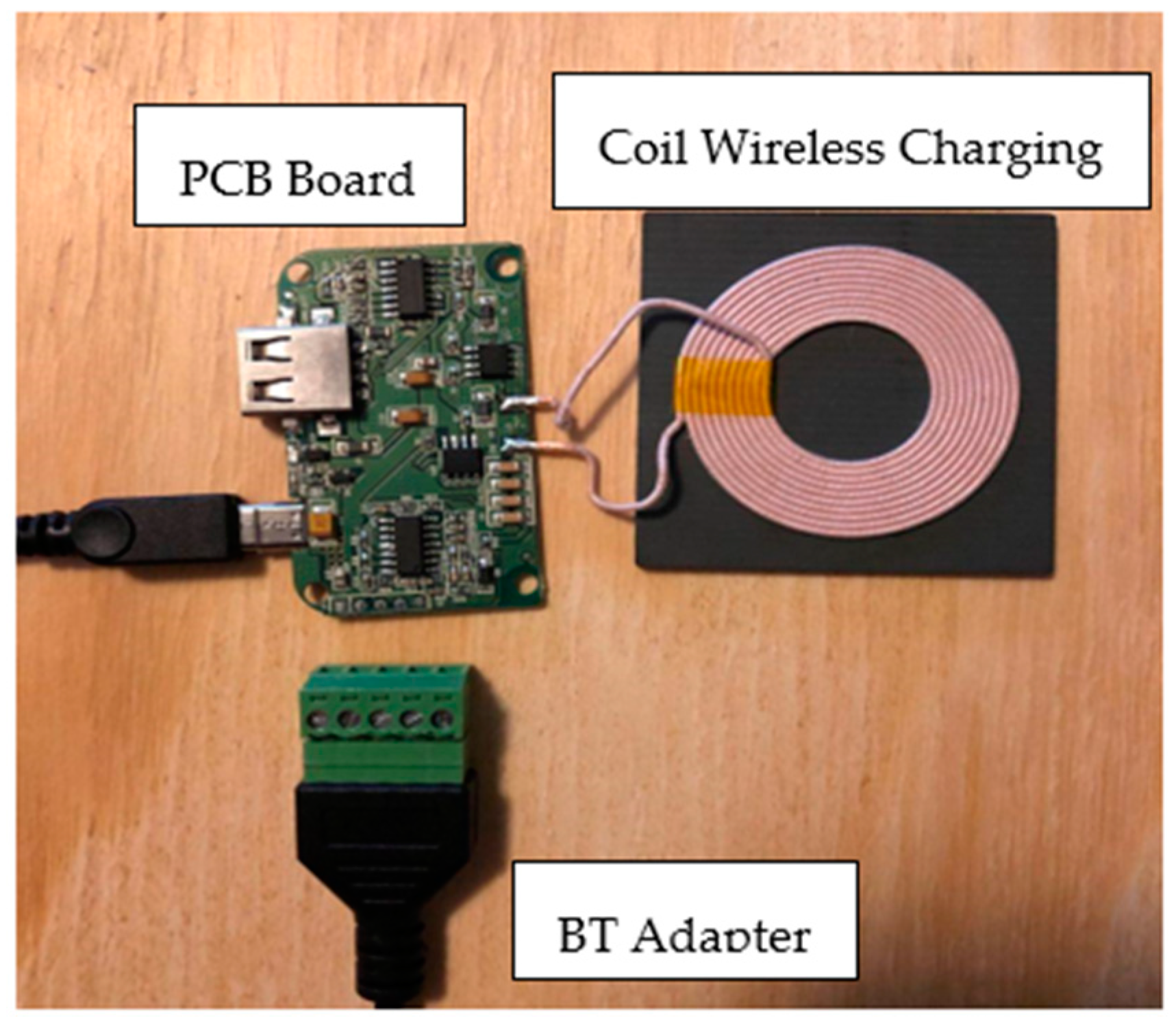
The data subsystem consists of a CY8CKIT-042-BLE-A Bluetooth Low Energy (BLE) Pioneer Kit, along with the PSoC Creator program, CySmart, an Android Galaxy S5 test device, and a custom mobile application we developed. The BLE pioneer kit will provide the hardware to communicate between the hardware and the application. The PSoC Creator program is a PC application that allows us to program the hardware according to our requirements. CySmart is Pioneer’s proprietary application that allows us an alternate method for checking our results.
The Qi (standard) wireless charger utilizing piezoelectric-generated power system is broken up into several different subsystems. The first subsystem is the generation subsystem, then the storage subsystem, followed by the wireless transmission subsystem. A data subsystem also allows the user to access logged values regarding generation, storage, and transmission.
Figure 6 illustrates a flowchart that shows an overview of the functional modules and data communication procedure. Below is a description of each subsystem:
Generation subsystem: Piezoelectric transducers and rectifying circuits that generate power from the mechanical stress from the user’s movement into electricity to be stored in the storage subsystem. Data is also logged.
Storage subsystem: Electrical energy from the generation subsystem is stored in the storage subsystem to later be utilized by the wireless transmission subsystem. Data is also logged.
Wireless transmission subsystem: Electrical energy from the storage subsystem is transmitted to a user’s device to charge it. Data is also logged.
Data management subsystem: the data logged by the generation, storage, and transmission subsystem is accessible by the user so that they may keep track of the individual activities of each subsystem.
Concerning the user, the system will behave as: The user will be generating electricity, storing it, and then eventually transmitting it via Qi (standard) wireless charging protocols. One user is capable of charging their device while another is generating. Additionally, the user will interact with the whole system using the software app to determine the charge level, voltage, and current. Additionally, this software includes communication between the Bluetooth Low Energy chip and the application.
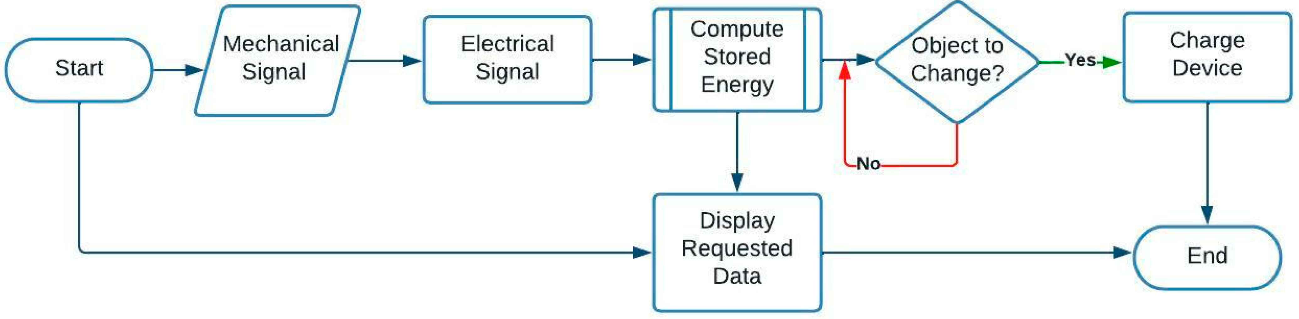
Figure 7 displays the data flow in the system to compute the stored energy and charge the device. Throughout the behavioral process of the system, the app obtains data by monitoring the electricity stored from the signals that have been generated and displaying requested data to the user. It also can sense if there is a device to be charged and proceeds to charge it if there is.
3.5. The Hardware Design and Implementation
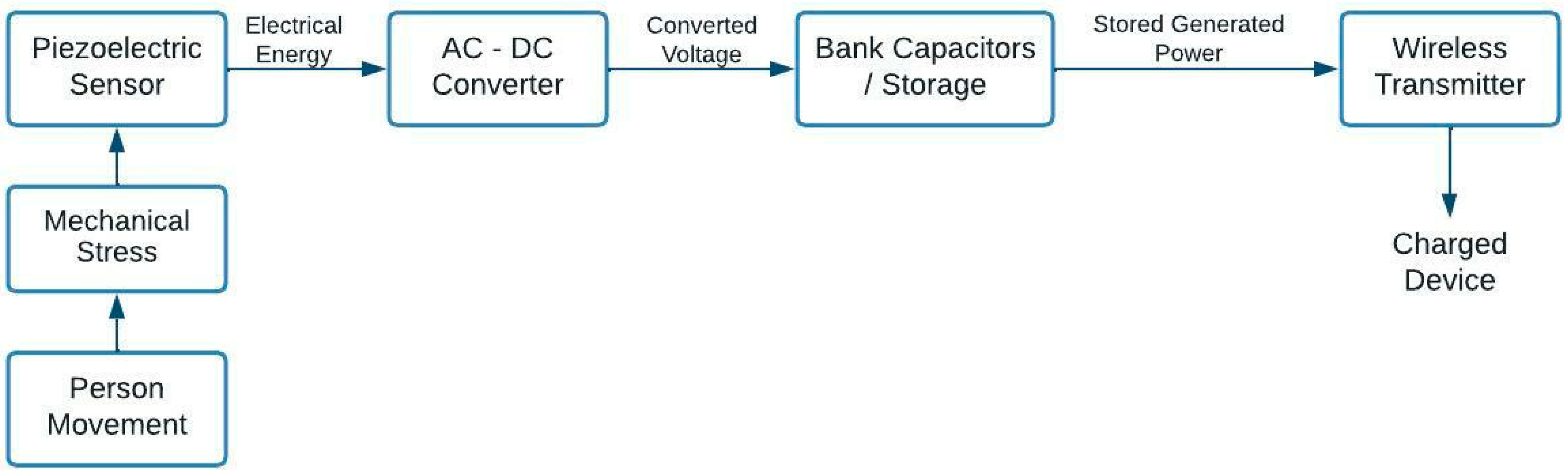
For the hardware implementation, we take the mechanical energy from a person’s movement and convert it into electrical energy via piezoelectric transducers. From there, we rectify the generated AC signal into DC and store the power in batteries. This power is then wirelessly transmitted to the user’s devices, allowing them to generate and charge.
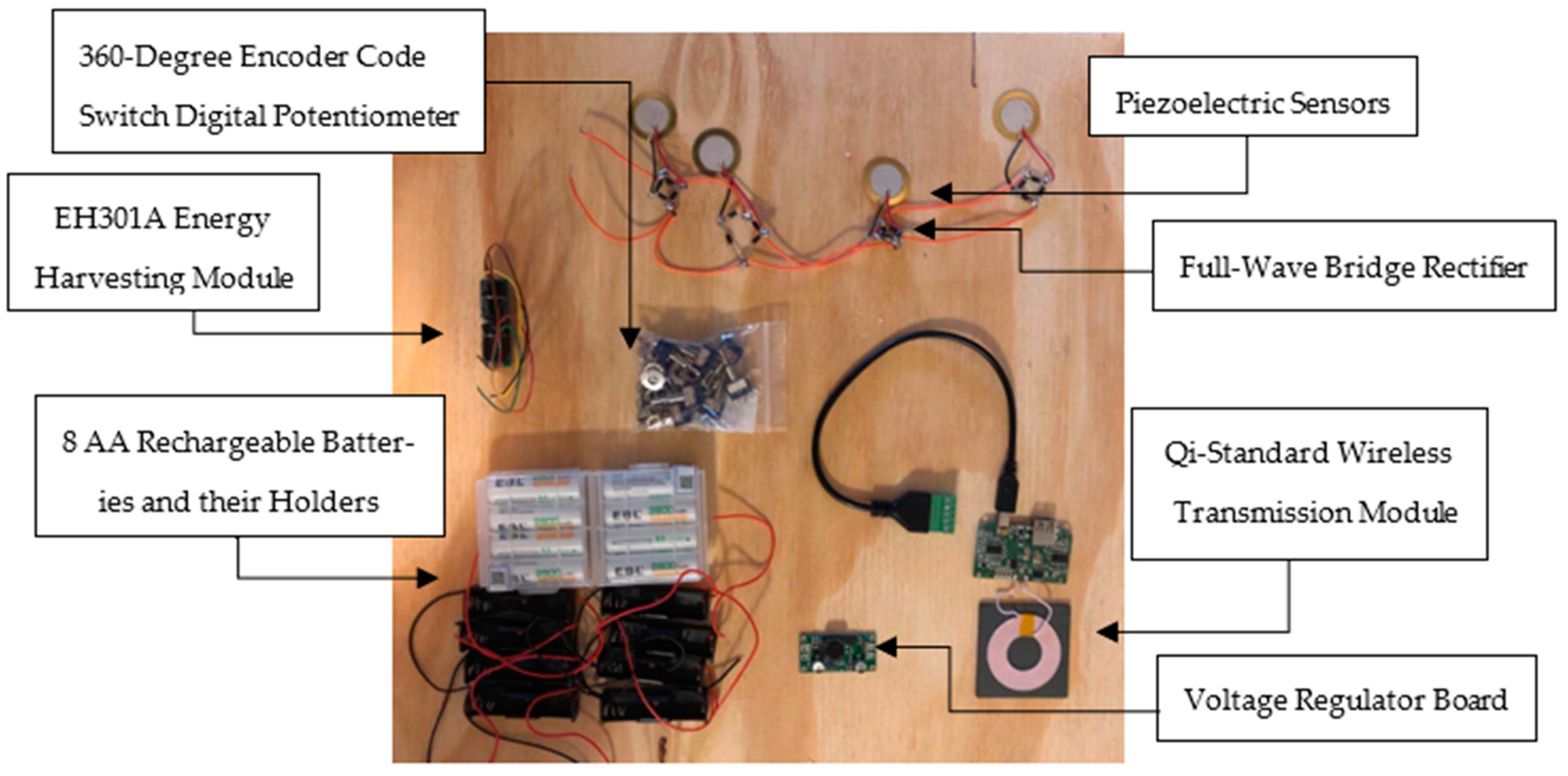
Figure 8 illustrates the communication process between the hardware components in steps of receiving signals, converting signals, transmitting, and storing the energy.
Figure 9 demonstrates the designed subsystem that illustrates the generation subsystem that consists of parallel-configured piezoelectric transducer devices, which are full-wave-rectified, that convert the original AC power to DC to avoid destructive wave interference along the supply lines. These lines are fed into the EH301A energy harvesting module. This module acts like a smart capacitor, allowing accumulated charge to burst into storage. Theoretically, this module’s useful energy output is 55 mJ of energy per cycle from various types of electrical sources, which can be used to power conventional 3.3 V and 5.0 V devices, but that is assuming the module does not have any energy input during firing mode. With only four of these small piezos, we could trigger the EH301A within a couple of minutes. With more of them, the power output of the generation subsystem could easily supply 17.2 W of power.
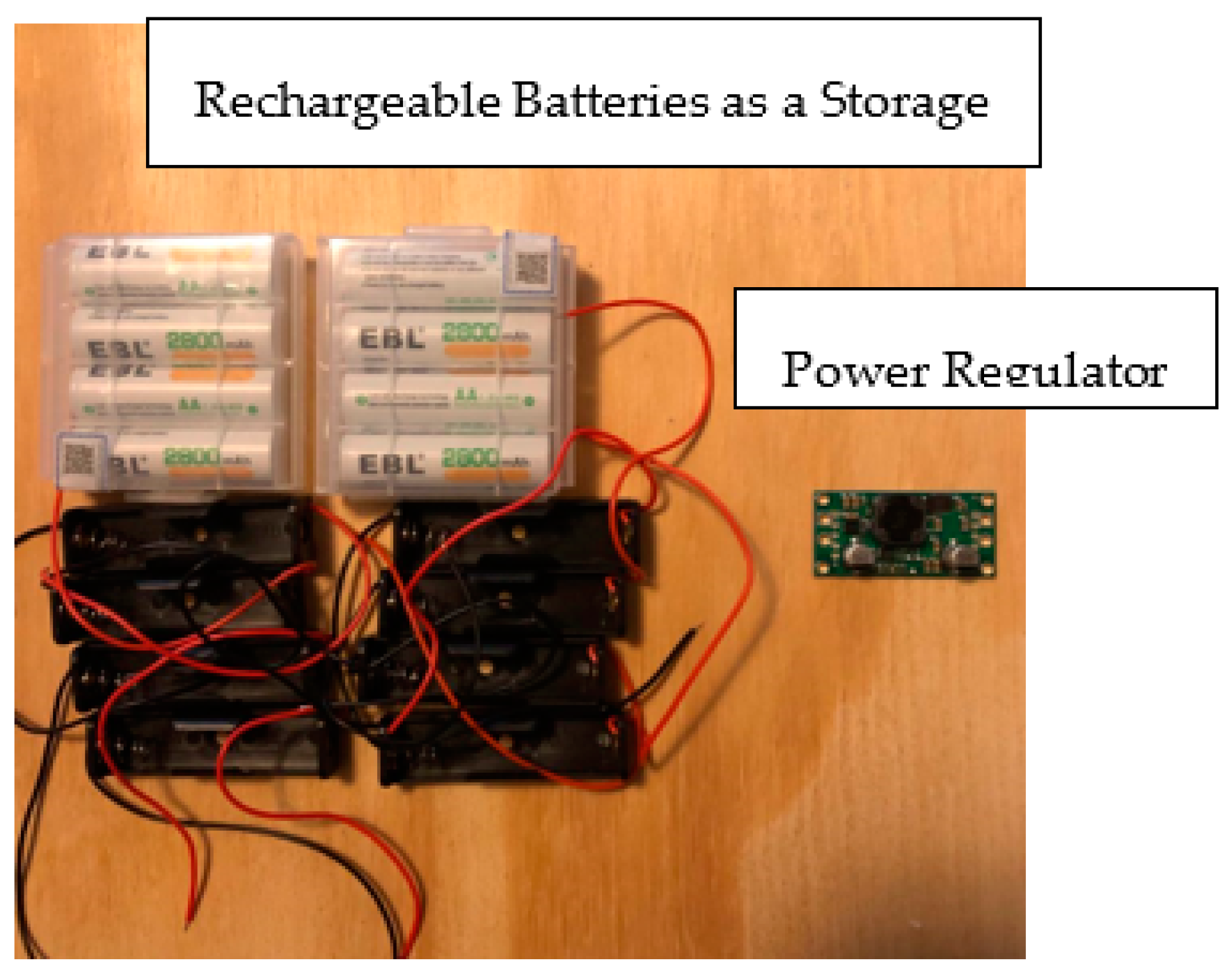
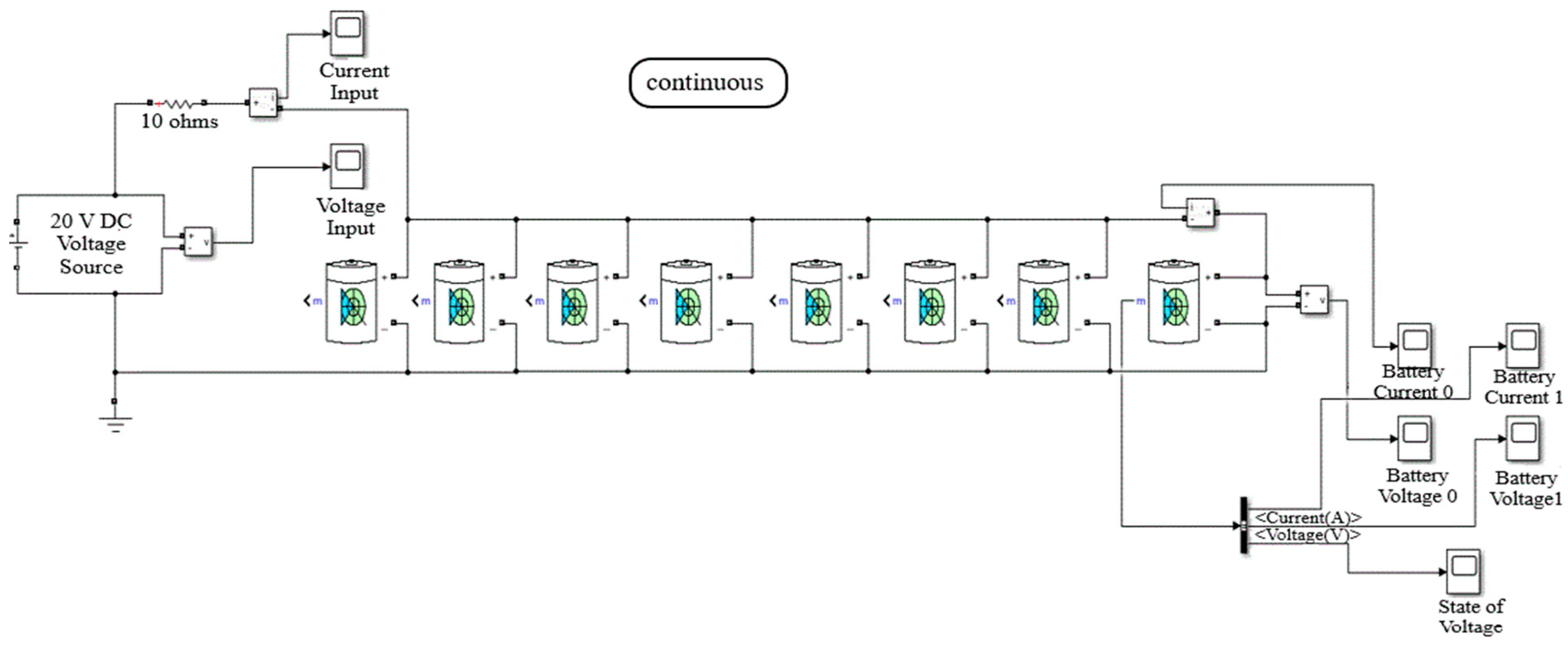
Figure 10 displays eight AA Nickel–Metal Hydride rechargeable batteries with their respective cells. We are using AA batteries for testing purposes. They are charged up from the EH301A energy harvesting module, then are discharged when we need to supply power to the Qi transmitter when we use it to charge any device that utilizes a Qi receiver. In our case, the user’s mobile device. A Pololu 5-volt step-up/step-down voltage regulator ensures a steady 5 V output. The function of this subsystem was simulated with Simulink. The battery elements were modeled to reflect the characteristics of our EBL AA’s. This is explained further in the next section: Graphical Data Results using Simulink simulations.
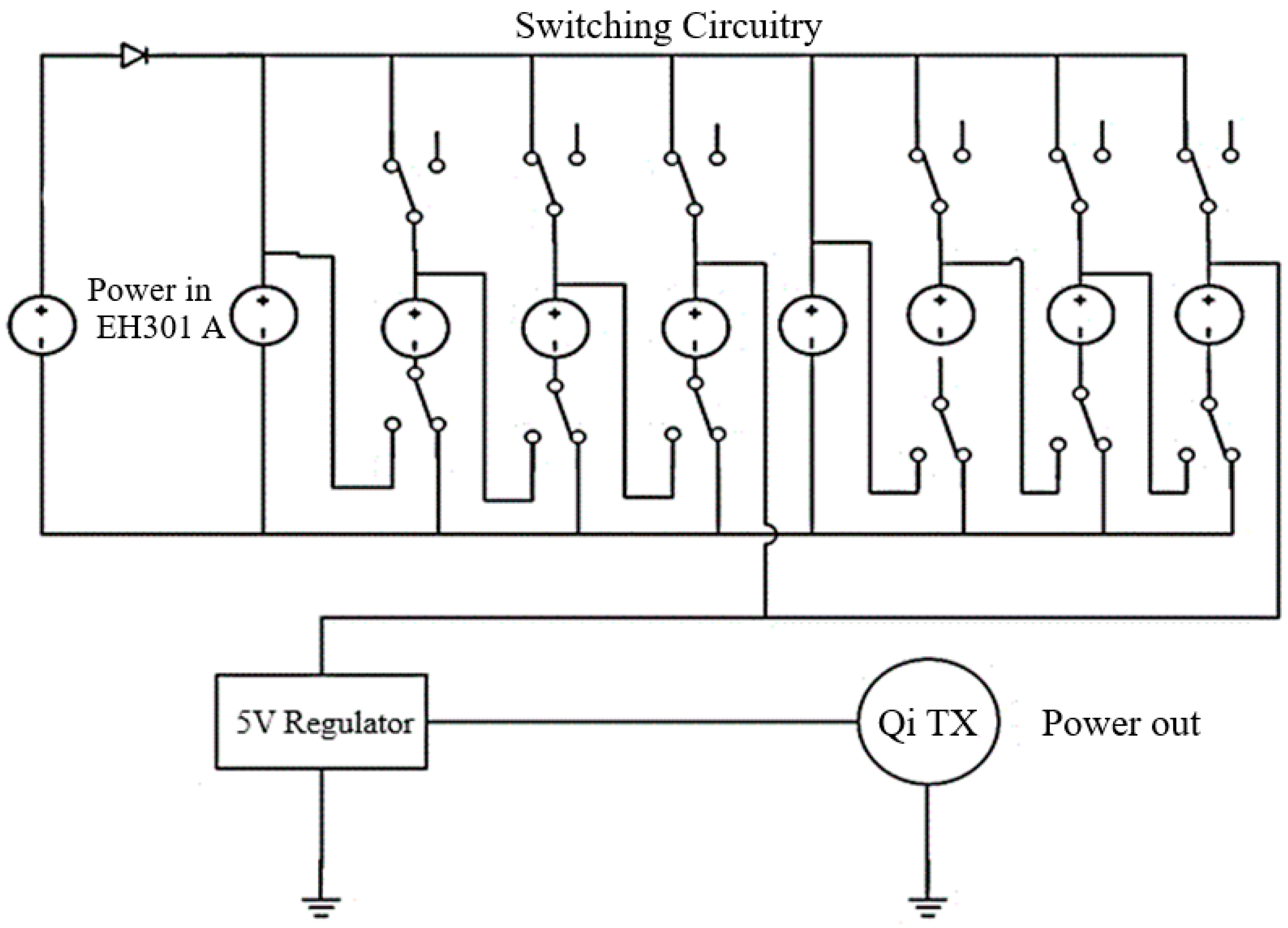
Figure 11 demonstrates a circuit design to display the relevant switching circuitry. Since the power flow must go from our kinetic input to our electrical output, switching circuitry was deemed necessary. To illustrate how, we can switch the (double A) AA batteries from being in a parallel configuration when they are charging to a double series branch configuration when they are discharging. This setup optimizes the flow of both inward and outward power. The EH301A energy harvesting module supplies the charge to the AA batteries in bursts, using a diode to prevent reverse current flow. The six switches on the top allow the positive side of the batteries to disconnect for the positive charging line. When switching from generation to transmission, these disconnect switches must be flipped first to prevent a short. Then, the bottom six switches can be flipped to disconnect the negative side of the batteries from the negative charging line and connect them in a series configuration. When switching back to generation from transmission, these bottom six switches must be flipped first to prevent a short as we flip the top six switches and reconnect the positive side of the batteries to the hot charging line. When the state switches from generation to transmission, the power is fed into a 5 V regulator to supply the proper voltage to the Qi-standard transmitter.
Figure 12 shows a universal Qi-standard wireless charging transmitter and receiver. The transmitter will use the power stored in the rechargeable (double A) AA batteries to supply charge to the receiver. Once the user places the mobile device on the coiled platform, a charge will be applied, and the mobile device will acknowledge that it is charging its battery. Our experimentation determined that the transmitter has a power factor of 5%. Theoretically, this value is reasonable because of the power loss inherent in the MOSFET transistor switching of the resonator circuit.
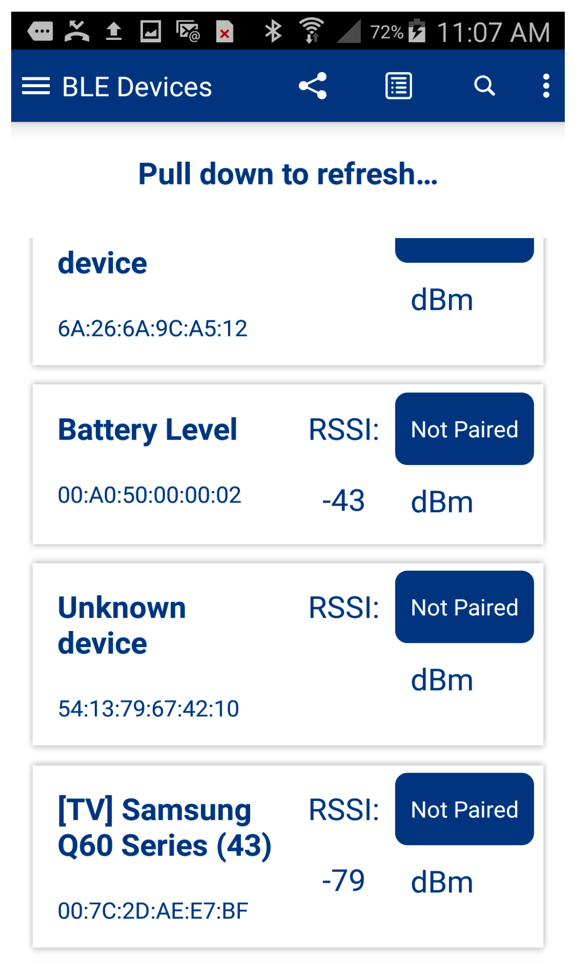
To allow the user to be updated and display the current status of stored energy, we designed an application. While we were able to transmit and display voltage measurements from the hardware using a proprietary application called CySmart, our custom application was able to transmit and display the measurements in the application logs.
Figure 13 and
Figure 14 display our custom Jasper Power application, along with menus displaying the values obtained from the measurements. The scan results from the proprietary CySmart application are shown in
Figure 15 to prove our concept and design.
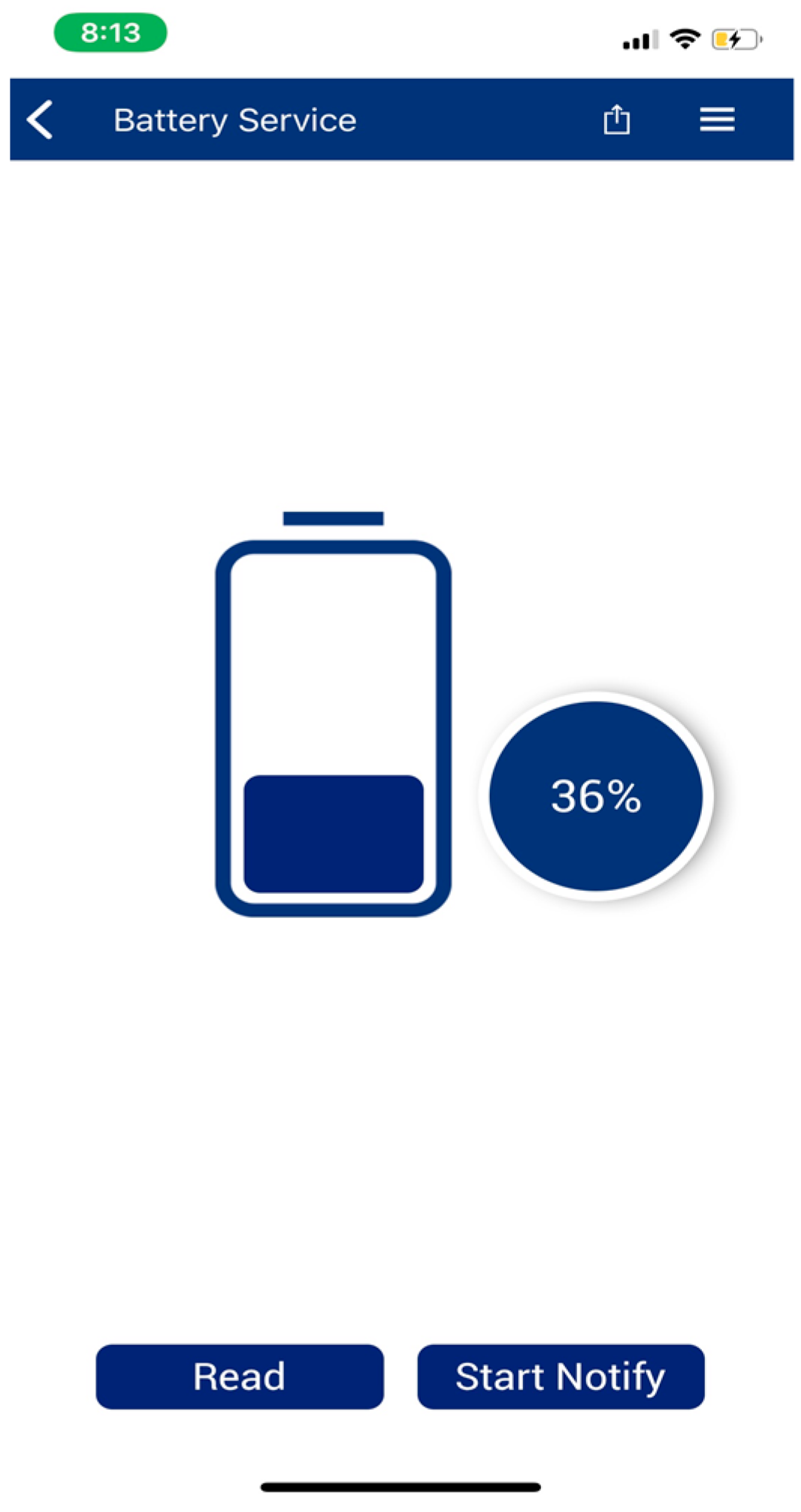
Figure 16 displays one of the data values obtained from the BLE chip after a connection is established in the CySmart application.
3.6. Implementation Results and Discussion
We were able to design the proposed architecture and implement our application. A number of tests and simulations were conducted.
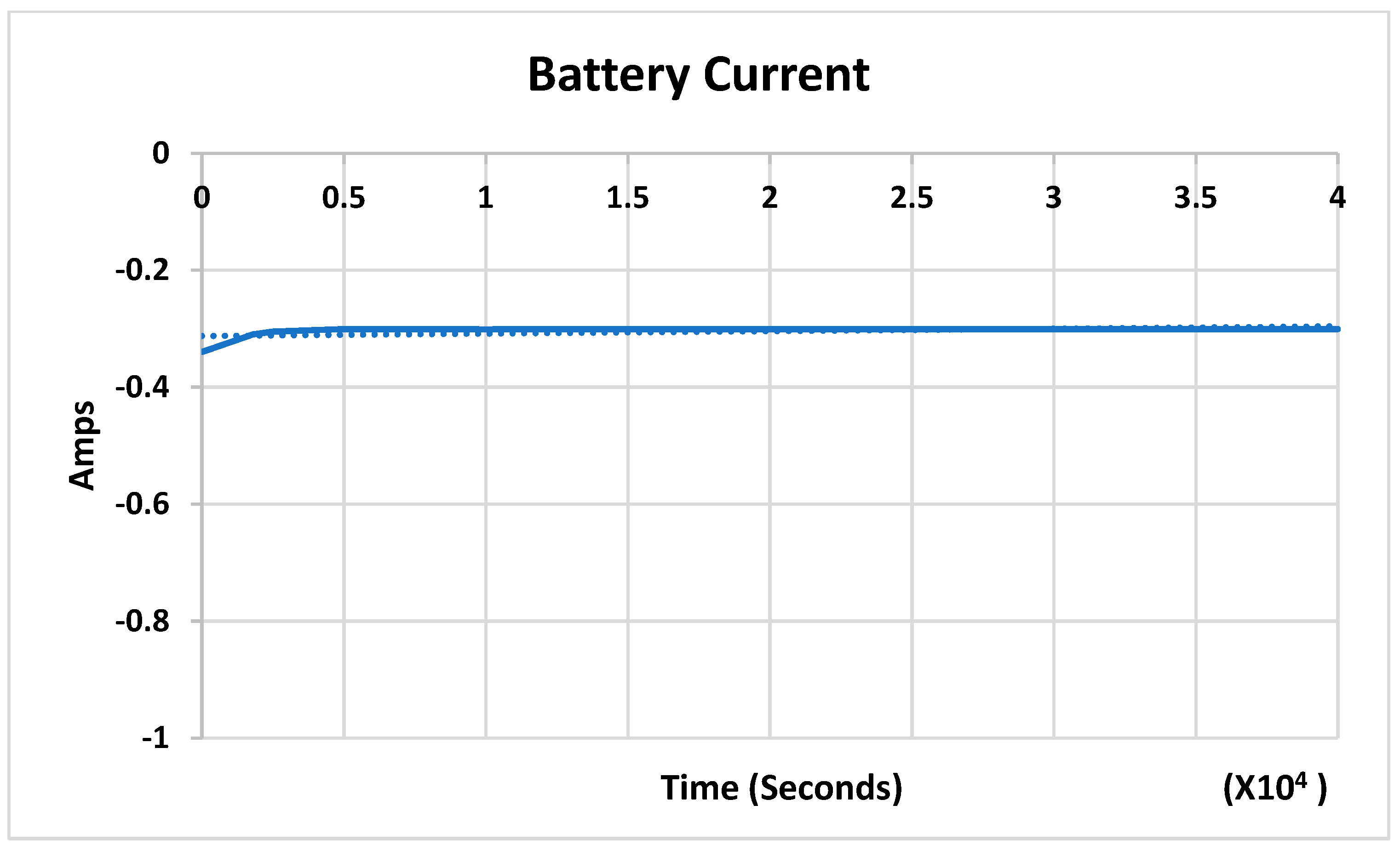
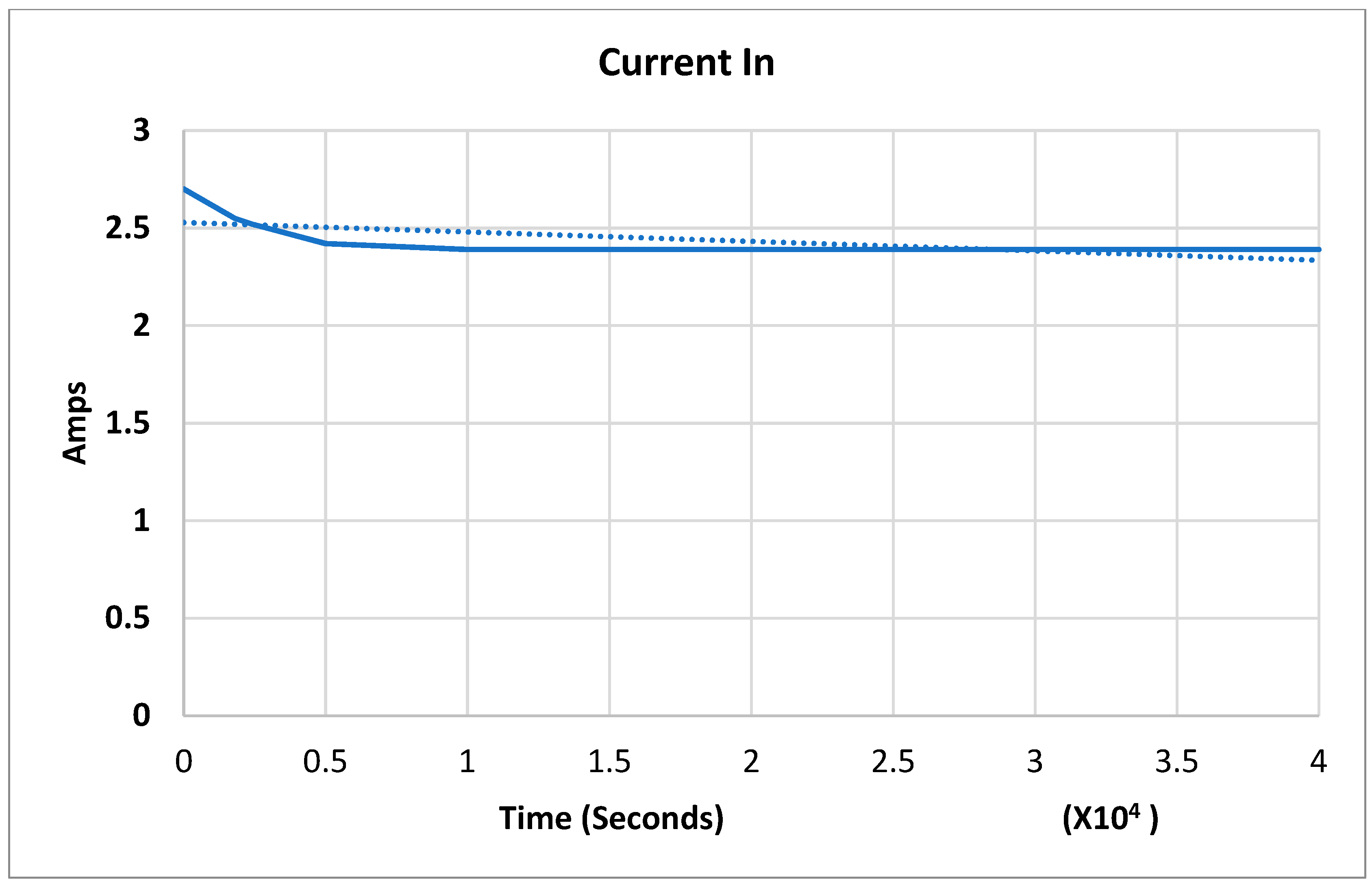
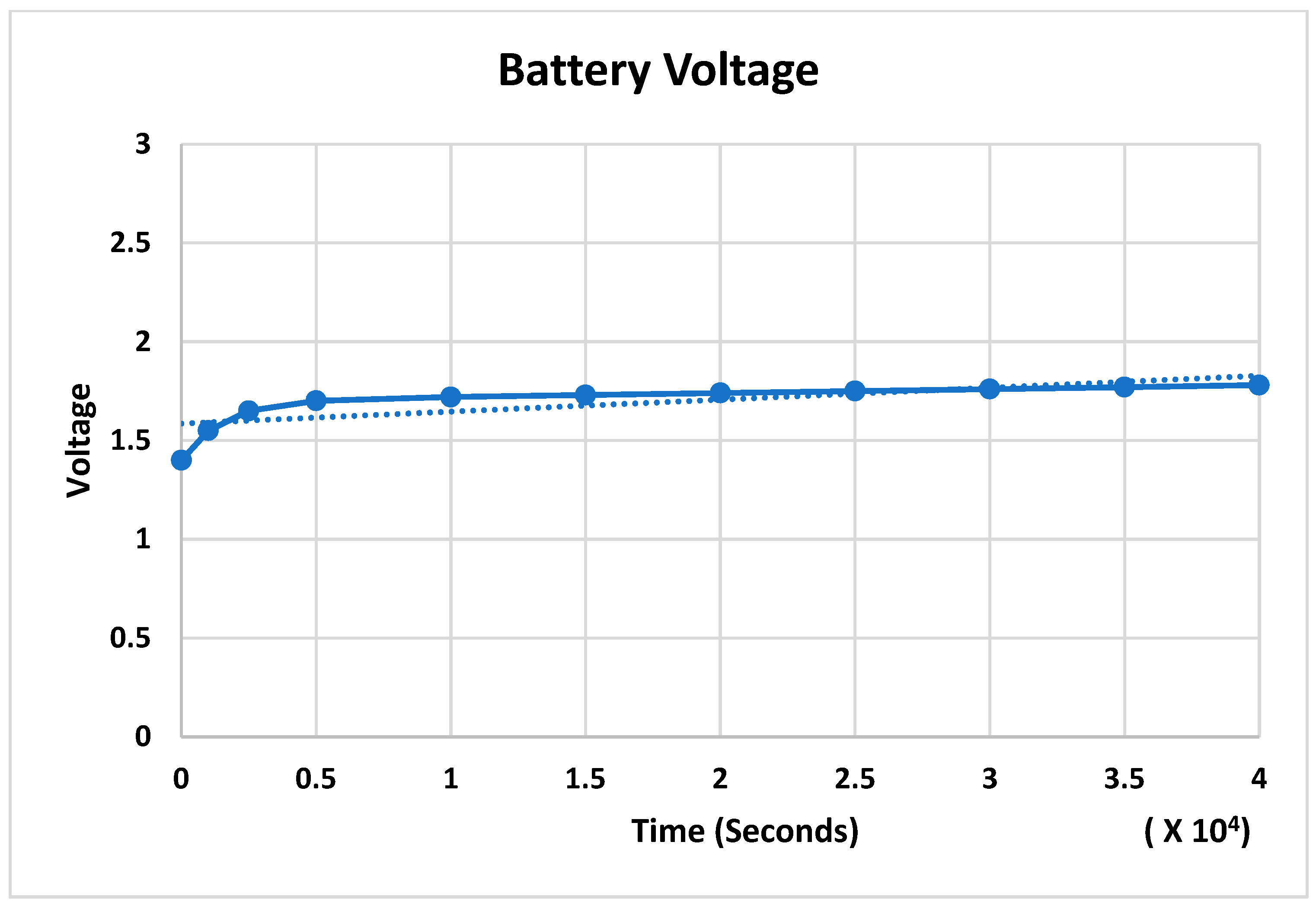
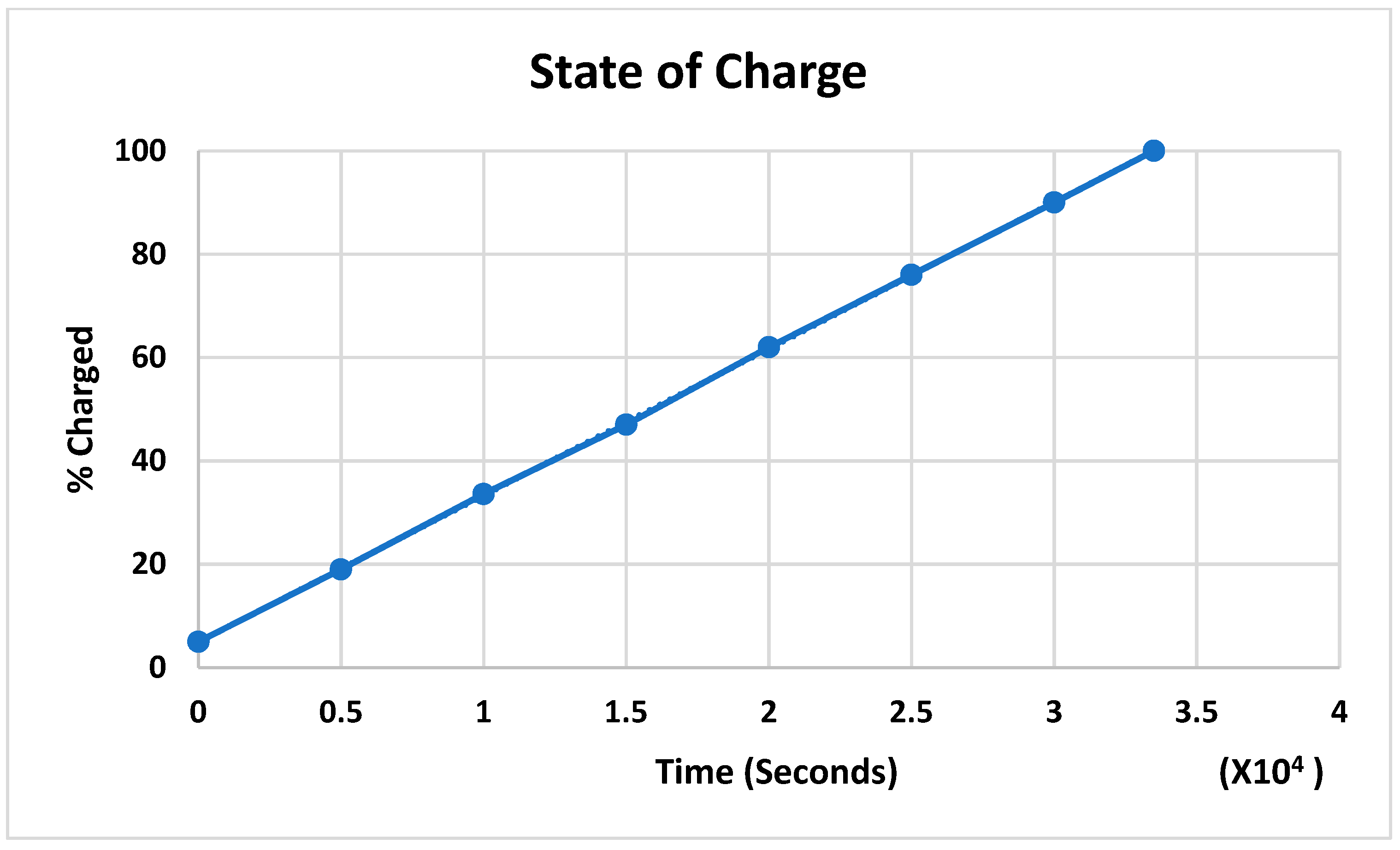
Figure 17 illustrates a Simulink simulation of the storage subsystem that is charging up from 5%. The input models the EH301A operating at a duty cycle of 1, assuming a constant power input. The simulation was run for 11.11 h, or approximately 70,000 (seventy thousand) joules of input. The relevant outputs are shown in
Figure 18,
Figure 19,
Figure 20 and
Figure 21, including the subsystem’s input current, the input current of an arbitrary battery, as well as the battery’s voltage levels and its state of charge.
Figure 18 and
Figure 19 demonstrate a current graph that illustrates the time in seconds for the
x-axis vs. amps for the
y-axis; a stable current and battery current were established after less than 0.2 × 10
4. The average current is 2.5 amps.
Figure 20 shows a voltage representation graph illustrating the time in seconds for the
x-axis vs. voltage values for the
y-axis; an average of 1.6 V is displayed for the battery and charging battery output. The voltage value shows stability over the testing period.
Figure 21 demonstrates a voltage representation graph illustrating the time in seconds for the
x-axis vs. the percentage of the battery changing for the
y-axis, and the exponential relationship was demonstrated as the state of a battery charging. The system successfully transmitted data and charged up to 100%.
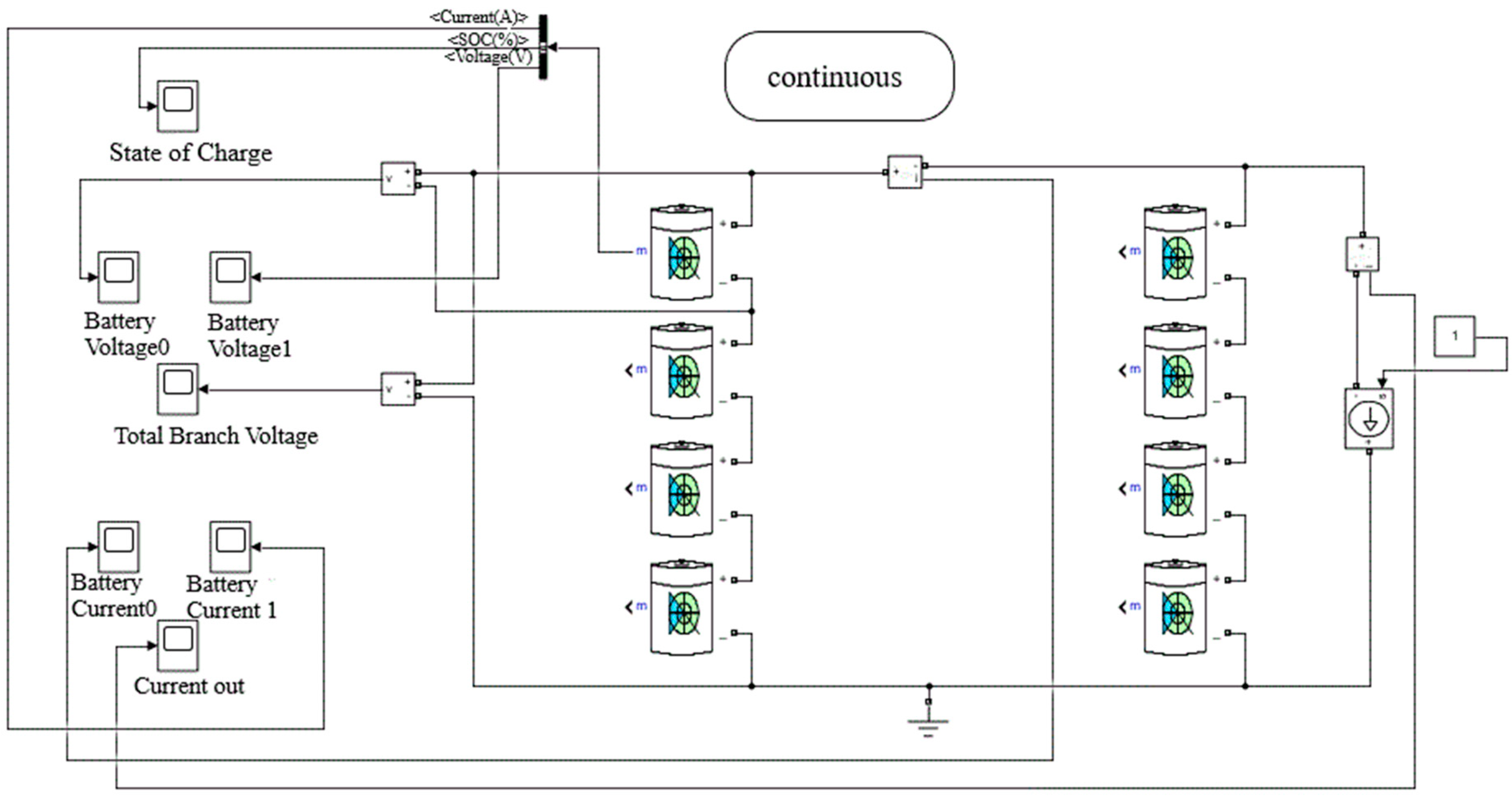
Figure 22 demonstrates a Simulink simulation of the proposed and designed parallel system discharging down from 98%. The output models a current draw of 1.5 A, representing the Qi transmitter’s average value. This simulation was run for 3.94 h or approximately 70,000 (seventy thousand) joules of output.
Figure 23,
Figure 24 and
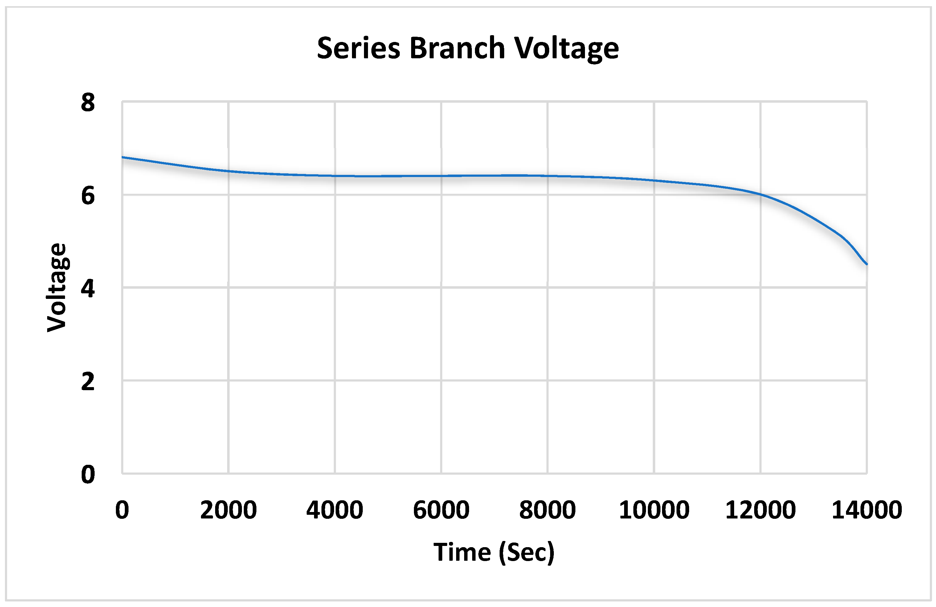
Figure 25 illustrate the voltage of an arbitrary series branch of batteries. As before, the battery’s input current, voltage levels, and state of charge are shown.
Figure 23 shows a series branch voltage graph that illustrates the time in seconds for the
x-axis (scale from 0 to 14,000) vs. voltage values for the
y-axis (scale from 0 V to 8 V); the voltage discharging status was demonstrated from 6 V to 4 V.
Figure 24 shows a battery current graph that illustrates the time in seconds as the
x-axis (scale from 0 to 14,000) vs. amps for the
y-axis (scale from −1 amp to 4 amps). Less than 1 amp is the discharging displayed value of current.
Figure 25 shows a battery voltage graph that illustrates the time in seconds for the
x-axis (scale from 0 to 14,000) vs. voltage values for the
y-axis (scale from 0.5 V to 3 V). From approximately 1.5 V to 1 V, the discharging voltage value was displayed.
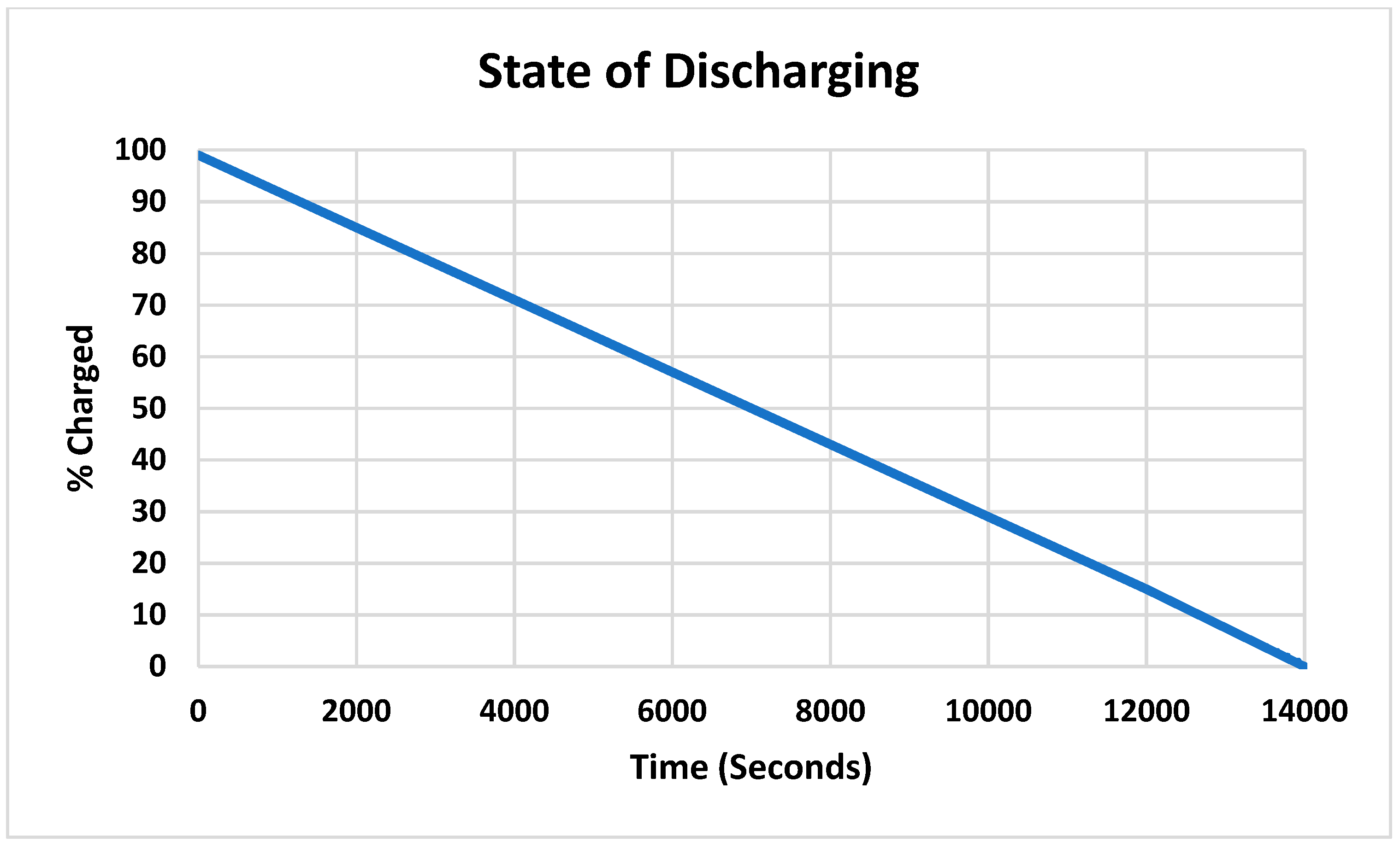
Figure 26 shows a state of charge graph that illustrates the time in seconds for the x-axis (scale from 0 to 14,000) vs. the charge percentage for the
y-axis (0% to 100%). The discharging status was displayed from 100% dropped to 0%.
The system was tested for several hours to ensure the battery’s current and voltage stability throughout the piezoelectric generator and charging scale. The system was able to generate and transmit power to devices successfully. On the basis of
Figure 13,
Figure 14,
Figure 15 and
Figure 16, users can monitor their devices’ charging status. The system can be utilized through different mechanical vibrations and strains in different applications. There is still space for improvement. To define our system’s performance vs. other power generators, we illustrated
Table 1.
Table 1 displays the power performance of each studied system. Most systems are limited to their applications and the type of charged devices, and also, the mechanical movement is restricted to the designed prototype.
On the basis of the State-of-the-Art Background section, we can conclude that our system is unique. It provided an affordable wireless charging solution using stored electricity that is generated from piezoelectric materials. This solution will adhere to Qi standards to be widely compatible with many devices. The parallel design of piezoelectric’s useful energy output is 55 mJ of energy per cycle from various types of electrical sources, which can be used to power conventional 3.3 V and 5.0 V devices. With only four of these small piezos, we could trigger the EH301A within a couple of minutes. This power generation percentage would increase as the number of piezos also increased. The power output of the generation subsystem could easily supply 17.2 W of power with more elements.
4. Conclusions
Recently, energy generation and wireless power transmission technologies have received significant attention. The need for clean energy generation technology and a reliable wireless transmission system has increased with the advance of wireless technologies. Wireless power transfer is the key to avoiding the battery replacement and recharging process. Our system presented the Qi standard to transmit gathered energy, as well as wirelessly. Piezoelectric harvesters are a very clean form of power generation. Our goal was to be able to store, monitor, and wirelessly transmit this power, which would result in lowering the difficulty and time required to access energy. A client application was developed to keep the user updated about the devices’ status.
We were able to satisfy our objectives that the system could effectively generate power, store the power in batteries, and wirelessly transmit the power. Despite our successes, we acknowledge some improvements we would like to implement in the future. Concerning the software, we would like to work on presenting the data in a format that is easy to visualize within the application menu instead of the logs. We also would prefer to further optimize our system by increasing its efficiency and data tracking capabilities.

 ,
, 


