1. Introduction
In cable duct production polycarbonate/acrylonitrile–butadiene–styrene (PC/ABS) is preferred over the standard material polyvinyl chloride (PVC) [
1]. This applies especially for some applications where compliance with the international standard UL94 for the flammability of plastic materials is required, e.g., in rail vehicle construction. Pure PVC releases (Cl
−) ions at elevated temperatures of approximately 210 °C and higher that can combine with free protons (H
+) from the ambient environment to form the hydrochloric acid (HCl) [
2]. PC/ABS materials, however, can meet the UL94 requirements without the addition of halogens, with the best rating being “v-0” [
3,
4].
However, burr and film formation is a critical side effect during the punching process of (PC/ABS) polymer blend cable ducts because it reduces the quality of the end product (
Figure 1). It should not only be avoided due to economic reasons but also because the resulting burrs might injure workers [
3] and endanger cables. This possible damage would risk the operational safety of the electrical system. Films, for example, can clog tools or bearings, causing problems in production and packaging and making an additional deburring process step necessary [
5]. However, at the same time, it increases the product price. Reducing burr and film formation is, therefore, of high interest for safety, market, and product quality reasons. Equally important is that production in one process step saves energy, machinery, and materials compared to several process steps, e.g., in downstream deburring, which leads to a more sustainable process.
Until now, most studies have focused on the material properties of PC/ABS aiming at the optimization and analysis of the material behavior by varying the mixing ratio of the PC to ABS, the butadiene content in the ABS, the process parameters during extrusion and mixing, and the optionally used additives [
6,
7,
8,
9,
10]. No analysis or optimization approach for the manufacturing process has yet been described. This study aims to avoid the formation of burrs and films by varying the dimensions of the clearance area and the process speed in order to optimize the product quality while reducing the production effort and the environmental footprint. Previous research indicated that the size of the clearance area and the process speed are the most influential factors based on the findings of DoE screening experiments. The clearance area was found to be the decisive factor influencing all quality characteristics that were considered [
5]. Furthermore, the influence of the process speed could be determined. The elongation at break of PC/ABS materials depends on the process speed. Higher process speeds lead to a reduction in the elongation at break and a decrease in its standard deviation [
11]. Additionally, the influence of the blank holder was determined as a vital process aspect and was adjusted with the aid of high-speed recordings [
12].
Here, the burr, film, cut surface, plastic flow, and shear droop quality characteristics are evaluated separately. Subsequently, we present the best process configuration regarding all quality characteristics and additionally a new approach for the dimensioning of the clearance. Additionally, the formally shown dependency on the process speed can be neglected in terms of the process quality.
Figure 1.
Burr and film formation on a punched-out section of a cable duct made of PC/ABS with an overview on the upper left side and the enlarged area (right) indicated by the red circle [
13].
Figure 1.
Burr and film formation on a punched-out section of a cable duct made of PC/ABS with an overview on the upper left side and the enlarged area (right) indicated by the red circle [
13].
3. Results and Discussion
Previous research identified the clearance as the decisive factor [
5]. In this study, larger material thicknesses were used, allowing us to evaluate fracture surfaces for the first time in depth. Due to the greater material thickness, the two cracks and their propagation were identified and explained in detail with the aid of excerpts from high-speed recordings (
Figure 3,
Figure 4,
Figure 5 and
Figure 6) [
12].
Figure 3 shows a slug after its separation from the material. Furthermore, the punch, material, and cutting die were clearly identified from this near-cross-sectional view using tools with rectangular geometries. In the following illustrations (
Figure 3,
Figure 4,
Figure 5 and
Figure 6), the punch was arranged above the slug. The image was taken exactly when the slug was ejected downwards through the cutting die.
When looking at the bottom edges of the slug (
Figure 3), the radii can be detected laterally, which turn into an inclined surface at a relatively constant angle. This slope is followed by a geometrically undefined section at the upper lateral part of the slug. The base material shows a similar but inverted crack surface. According to the literature [
15], the clearance is dimensioned correctly if the crack initiated at the die side and the crack initiated at the punch side grow towards each other until they meet.
An under-dimensioned clearance area and the associated fracture surface are shown in
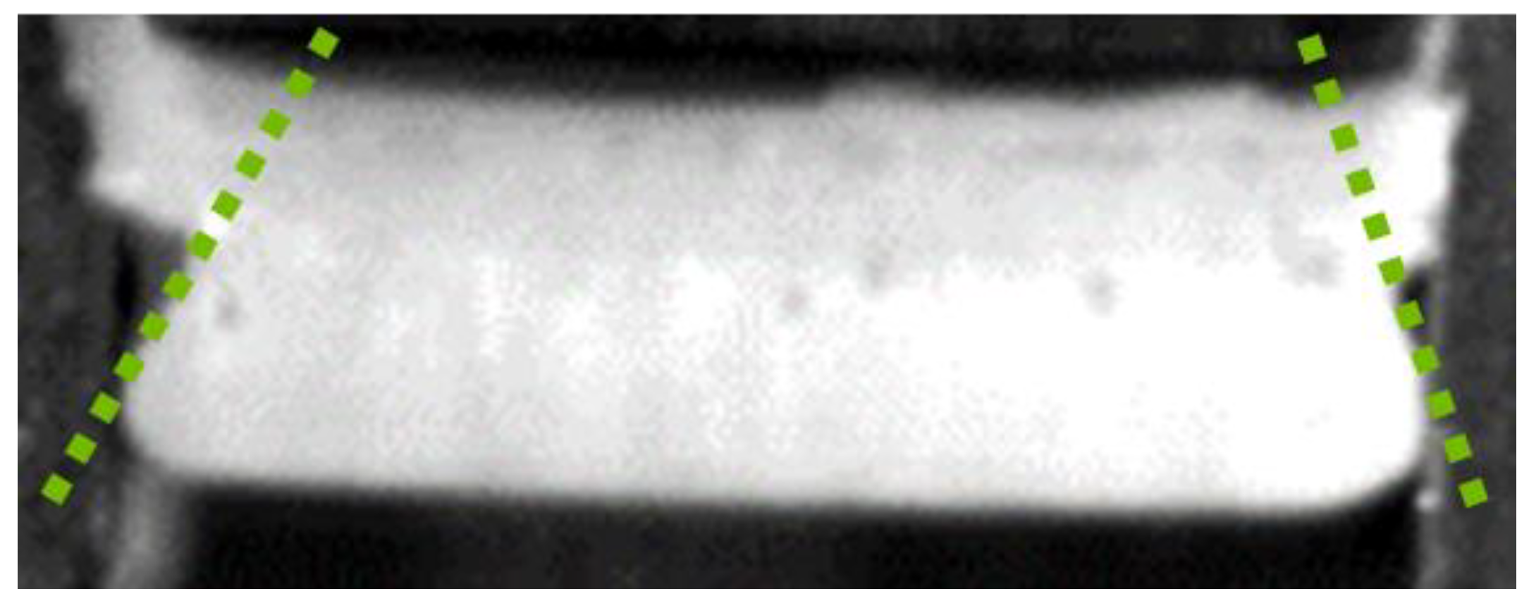
Figure 3. The crack on the punch side proceeds outside of but parallel to the green lines, leaving a geometrically undefined section in the upper part of the slug (
Figure 4), which is macroscopically observable on the base material. The cracks are located under the shear droop in the upper part of the material. The undefined section in between the two cracks was centrally separated by the punch. The final result was a ruptured, fractured surface on both the base material and the slug.
If the direction of the crack propagation or the inclined surface is virtually extended from its origin at the die side, ideal but simulated slugs are formed (
Figure 5). This can be achieved either digitally by manipulating figures or practically by cutting off the upper parts of the slugs along the inclined surface (dashed lines).
A rectangular triangle can be detected on each side of the simulated slug (
Figure 6). The flanks represent the clearance and the material thickness. Furthermore, the angle of fracture α can be seen.
For later tool or clearance design, this procedure is repeated several times to calculate the mean value of the ideal clearance. Another possibility is to determine the angle of the inclined surface in order to calculate the clearance using the following formula:
c: clearance in mm;
t: material tchickness in mm;
α: angle of fracture in °.
Due to the distinct experimental approach, the clearance measurements are not necessarily exact. It is, therefore, advisable to test a certain range. For this reason, 5 tools in the relevant range and 2 additional tools were tested to show the impacts if the clearance dimensions were too large and too small.
Table 1 shows the results of the experiments with varied clearances. The images of the front or punch side display the shear droop, while the images of the rear or die side display plastic flow. The images of the die side were taken at a viewing angle of approximately 30° to display the cut surface quality, burr, and film. Note that the quality characteristics in the considered area are clearly independent of the process speed, as tested in this experimental setup. This contradicts the earlier findings [
11]. The burr, film, cut surface quality, plastic flow, and shear droop characteristics are described, evaluated, and discussed in detail below.
Burrs: Burrs are defined as geometrically undefined material overhangs on the underside of the punch-out. No significant burr formation was visually detected in any of the experiments. For clearances smaller than 1.2 mm, however, rough areas could be felt but not seen. This effect increased with the decreasing clearance. In the area tested and for clearances larger than 1.2 mm, no burrs were touch-detected. Due to the qualitative nature and time constraints of the present work, the authors suggest that a further optical analysis, such as via SEM, be conducted to substantiate the findings described.
Presumably the surface that feels roughened is not a burr as such but the origin of the crack on the die side. If this crack does not exactly meet the crack on the punch side, a so-called tear-off edge is formed. The effect increases as the distance between the cracks increases as a function of the increasing clearance. The opposing cracks meet ideally at a die diameter of 10.4 mm. With smaller diameters the tear-off edge becomes more explicit.
Films: Thin, partially translucent material flakes are referred to as films. According to previous research, a film is caused by the influence of heat and over-expansion of the material in the clearance [
12]. Films did not form in any of the experiments.
These findings now amend previous investigations and experimental setups chosen by the authors [
5,
11,
12,
13,
14]. In previous investigations, tools with small clearances (e.g., 0.066 mm) compared to the tools described here were tested. Those dimensionally small clearances resulted in increased film formation [
5]. In contrast, none of the relatively large clearances tested in this study resulted in film formation, supporting the assumption that films are caused by friction or heat. Reducing friction mainly reduces the heat input. Therefore, the larger the clearance, the less friction between the tool parts and the material, consequently reducing film formation during the punching process. Due to the lower friction, the tool life is increased. This results in a reduced demand for tools and lowers the environmental impact of the process. This theoretical approach is supported by former studies [
12] showing that either the film is formed in the clearance or the material re-solidifies in the clearance as a film. Since PC/ABS is a thermoplastic polymer blend, it can be assumed that the material melts locally during the process and reshapes as a film caused by geometric boundaries and the heat input.
Cut surface quality: To determine plastic flow and discuss the cut initiation and crack propagation, it is important to evaluate whether the cut or fracture surface is smooth or whether it is cracked. An example of a cracked cut surface can be seen in the image showing the die side at a viewing angle of 30° with a die diameter of 9.5 mm. This effect decreases with the increasing clearance regarding the area that is considered.
The shape of the cut surface strongly depends on the local crack initiation and recombination; that is, whether the crack initiated on the punch side and the crack initiated on the die side meet each other ideally. If the clearance is too small or too large, the cracks will propagate past each other, resulting in a surface gap (
Figure 7, demonstrated for small clearances using cutting dies smaller than 10.4 mm). A similar shape for the cut surface was expected for large clearances, but for cutting dies larger than 10.4 mm a good cut surface quality was obtained. Additionally, the plastic flow of the punched-out area was observed. Possibly the plastic flow occurring when large cutting dies are used influences the dependence of material thickness and clearance causing the cracks to meet, which then results in a good cut surface quality.
Plastic flow: When the die diameter exceeds 10.5 mm, a rounded boundary around the punch-out is visible on the die side when looking at the die at an angle of 90° and a diameter of 11 mm. This is associated with the plastic flow of the PC/ABS material surrounding the punch-out.
For small clearances, the die or its cutting edges can probably be assessed as a kind of “counter bearing” to the punch. The material to be punched is supported by the die and cannot yield. The larger the distance of this so-called “counter bearing” to the process action point, the more the material’s structure has to transfer the occurring stresses to the “bearing point” (die) via an “unsupported length” (clearance). In the unsupported area, the overall stress probably excesses the yield strength of the PC/ABS, resulting in plastic flow. The PC/ABS molecules stretch locally and align and compact. Most likely this alignment and concentration of several molecules in a reduced space leads to a local increase in mechanical strength. As soon as the strength has increased sufficiently, the present (shear) stresses can be transferred to the “counter bearing” without further material deformation. Consequently, the stress at break is locally exceeded. As a result, an ideal punch-out remains, which is geometrically shifted into the direction of the die due to the plastic flow. It is most likely that the caved-in shear droop is a side-effect of the plastic flow.
Shear droop: Starting from a die diameter of 10.2 mm and above, a caved-in shear droop is visually detectable on the punch side at the boundary of the punch-outs. The shear droop becomes more present as the dimensioning of the clearance increases. Small clearances result in relatively small radii or a small shear droop. However, as the clearance increases, the central area of the radius collapses. The cross section of the radius approximately describes a quarter circle, which becomes more S-shaped as a function of the increasing clearance. This is best demonstrated for a die diameter of 11.0 mm when looking at a punch-side image. In addition to the effect of the collapsed shear droop, the area of the external influence or the plastically deformed area increases, as demonstrated by the outer diameter of the shear droop on the punch-side images. This outer diameter increases as a function of the increasing clearance.
Dimensioning of the clearance: Derived from the present results and considering all quality characteristics mentioned above, a clearance of 1.2 mm is considered as the optimal choice, as this results in neither burr nor film formation. Furthermore, the cut or fracture surface is not cracked and no plastic flow is visually detectable. The only negative aspect is a slightly caved-in (S-shaped) shear droop. However, this probably only causes an atypical or unusual shape of the punch-outs, still allowing for satisfactory quality characteristics such as the burr and film formation.
Overall, the approach for dimensioning the clearance is regarded a success. If the clearance is already dimensioned close to the correct value, the following rules can be applied:
If plastic flow is present, the clearance is too large;
If there is a cracked cut surface, the clearance is too small.
It is still necessary to clarify whether any disadvantages result from the increased angle under which the material is sheared. Since there is a rounding on the punch side and an obtuse angle on the die side, cable routing or damage is less likely. If the punch-outs are used for mounting of the cable duct, static problems could arise. However, these can easily be overcome by using suitable inserts, which could possibly be made from the slugs. The use of add-on parts and special inserts for the installation of cable ducts is already common practice today. In addition, an increase in tool life is likely, since the load on the tool is reduced by increasing the space and reducing the friction and process temperature. This means that fewer tools have to be produced, transported, and changed, which saves on resources.
Correlations: All quality characteristics presented here depend on the clearance. The film cannot be detected in any of the tests. However, this is attributed to the relatively large clearance and the resulting reductions in friction and heat input. The clearance directly identifies the distance between the crack initiation on the punch side and on the die side. Since the cracks grow at relatively constant angles, the clearance determines whether or where the cracks meet. If the clearance is too large, plastic flow occurs. Plastic flow occurs because the tensile strength of the material is exceeded. The tensile strength is probably locally exceeded due to a lack of support of the material in the area of the clearance. This effect may also be responsible for the collapsing shear droop. The material flows or is forced to flow from top to bottom. It is assumed that due to the altered geometric proportions of the clearance and material thickness caused by the plastic flow, the punch-outs have a good cut surface quality in spite of the oversized clearance. If the clearance is too small, the crack initiated on the punch side and the crack initiated on the die side will grow past each other. This consequently leads to a so-called tear-off edge for relatively small deviations from the ideal clearance. As the clearance decreases further, however, the crack initiation becomes more visible. This is caused by the cracks not meeting each other in an ideal manner, resulting in material remaining. It is, therefore, assumed that the burr that is presented is not a burr as such but material residue of a sub-optimal material separation.
The newly smooth cut surfaces can injure neither the workers nor the cables. Furthermore, the incorporation of dirt particles or germs is much more limited due to the closed cut surface compared to the heavily fissured cut surfaces evaluated up until now. This could particularly be advantageous in areas with increased hygiene requirements, such as the medical industry or food industry. In summary, the quality of the component and the process is increased while the production costs are reduced.
It would be of interest to examine the various polymers and material thicknesses with regard to their fracture angles in order to find the underlying physical relations. Once this has been found, a universal formula for the dimensioning of the clearance in relation to the relevant material characteristic might be developed. First, preliminary tests with varied material thickness have shown that most likely there is no linear relationship between the material thickness and clearance for PC/ABS.
Several qualitative characteristics may be improved by varying other tool and process parameters. However, the high-speed images clearly show the extraordinary influence of the clearance on the punching process, whereas the process speeds in the tested range are of no relevance.


