Article

Evaluation of the Use of Different Dedicated Mechanical Subcooling (DMS) Strategies in a Water Source Transcritical CO2 Heat Pump for Space Heating Applications

by
Fernando Illán-Gómez
1,*,
José Ramón García-Cascales
1,
Francisco Javier Sánchez-Velasco
1 and
Ramón A. Otón-Martínez
2
1
Departamento de Ingeniería Térmica y de Fluidos, ETSII, Universidad Politécnica de Cartagena, C/Dr Fleming s/n, 30202 Cartagena, Murcia, Spain
2
Departamento de Ingeniería y Técnicas Aplicadas, Centro Universitario de la Defensa en la Academia General del Aire, C/López Peña s/n, 30720 San Javier, Murcia, Spain
*
Author to whom correspondence should be addressed.
Clean Technol. 2022, 4(4), 1208-1226; https://doi.org/10.3390/cleantechnol4040074
Submission received: 28 June 2022 / Revised: 30 October 2022 / Accepted: 11 November 2022 / Published: 17 November 2022
(This article belongs to the Special Issue Synergistic Technologies to Advance in Sustainable Refrigeration)

Abstract

:
In this work we analyze numerically different design configurations to be used in a R1234yf DMS cycle coupled with a water source, transcritical CO2 heat pump for heating applications in the building sector. Specifically, we study the temperature range proposed by a European standard for heating with inlet/outlet water temperatures of: 30 °C/35 °C, 40 °C/45 °C, 47 °C/55 °C and 55 °C/65 °C. Moreover, 25 °C/30 °C is also analyzed which is the range expected for indoor swimming pool water pool heating applications. A water inlet temperature of 10 °C at the evaporator was considered in all of the cases. Results show that depending on the coupling strategy between the DMS cycle and the CO2 heat pump, optimal COP values obtained can vary up to 30% whereas the optimal operating pressure of the CO2 cycle can vary up to 8%. A configuration based on splitting the water flow to be heated into the DMS condenser and the gas cooler in a system with IHX was the best option for all the temperature ranges studied. The improvement in the maximum COP values obtained with this configuration ranges between 5% (for swimming pool applications) and 25% (for space heating with 40 °C/45 °C) when compared with the base cycle depending on the water temperature range considered. When this configuration is not considered, the basic transcritical CO2 with IHX and without DMS was found the best option.

1. Introduction

The use of heat pumps for low and medium heating applications is experiencing a general boost especially in the current global scenario of increased energy prices. Worldwide many governments are promoting through their energy policies the use of this clean technology. For example, the European Green Deal is boosting the use of this technology for domestic hot water (DHW) production and heating in order to reach higher energy efficiency rates in the building sector.
Based on legislators’ and users’ interest, research lines on heat pumps are moving toward refrigerants of type A1 (i.e., non-toxic and non-flammable) with null ozone depletion potential (ODP) and very low greenhouse warming potential (GWP). In this case, CO2 raises as an interesting candidate as it is an A1-type, natural refrigerant which is cheap, has a GWP of 1, and a null ODP. As the critical temperature of the CO2 is relatively low, in a heat pump for water heating applications, CO2 operates in a transcritical regime. This means that the pump will either work in a subcritical thermodynamic cycle if the temperature of the water to be heated is relatively low, or in a transcritical or supercritical thermodynamic cycle if the temperature of the water to be heated is higher. In this application, the water is heated in the heat exchanger located at the high-pressure side of the thermodynamic cycle. This heat exchanger is called “gas cooler” as it does not promote a phase change in the refrigerant when the heat pump operates in a supercritical cycle [1]. When promoting energy efficiency in buildings, an interesting solution for heating applications is the use of the greywater, wastewater, or sewage of the district building network (i.e., collectors or lines) as a heat source of the evaporator in a water source heat pump [2,3,4,5,6,7,8] due to the fact that the greywater has a higher temperature than the one of the outdoor ambient air. In this case, the use of main district collectors of the blocks/neighborhood can help to compensate for potential variations of the greywater/wastewater flow available that might be present in individual house wastewater lines or deposits.
The use of greywater/wastewater networks as heat source has focused the attention of many researchers since the 1980s. In the open literature there are many studies dealing with the performance of this type of systems and the coupling to the water heat source. Gu and Deng [9] studied the feasibility of using urban wastewater heat as a heat source in a water to water heat pump. They indicated that indirect-type systems i.e., the ones that use an intermediate water circuit between the wastewater network and the heat pump evaporator, required less quality in the wastewater treatment; however, they provide 7% less energy saving than the direct type systems. As stated by Culha et al. [4] it is clear that the selection of heat exchanger technology and quality requirements is a key issue in this type of heat pump system as they may deal with treated or non-treated wastewater flows or sewage effluents [10]. According to [6,7], shell-and-tube heat exchangers along with plate heat exchangers are the most common for liquid-to-liquid applications; however, also spraying film and immerse types of heat exchangers can be found for wastewater source heat pump applications [3,5]. All in all, these systems have some environmental challenges as Ni et al. [11] stated. Thus, research efforts must be maintained in this technology in order to improve the designs.
Regarding the efficiencies reached by this type of heat pumps, Zhou and Li [12] pointed out in a theoretical and economic study for China climates that COP can reach 3.5 to 4.5 in winter. Many of the studies used third generation refrigerants (HFC), being R-134a the most common among them [7,13,14,15,16,17]. For example, for this refrigerant [7] reported COPs of the order of 2.46–2.9 for wastewater temperatures of 27 to 33 °C and hot water production of 40 to 55 °C. In the case of [14], they reached a COP of 3.6 with wastewater temperatures of 6 °C and discharge temperatures of 50 °C. Other experimental works found that R410A [18] and R407A [19] provided COPs between 3.55 and 5.5 when inlet wastewater temperature ranged between 20 and 26 °C and the domestic hot water was heated up to 60 °C from 10 °C in the case of [18] and from 26 °C in the case of [19]. According to [20], R22 provided the same range of COP values when inlet wastewater temperature ranged between 11 and 35 °C and the domestic hot water was heated from 35 to 53 °C. The use of CO2 as refrigerant in these applications is experiencing a new boot due to the negative impact on global environment of the synthetic halocarbons that replaced CO2 as refrigerant decades ago [1]. Moreover, as shown by [1,19], CO2 has better heat transfer characteristics than fluorocarbons. Moreover, the pressure ratios of the CO2 cycles are lower than those of R22 for the same range of evaporation temperatures [21], which may provide lower compressor consumption for a CO2 cycle than for a R22 cycle.
Previous investigations have shown that the coefficient of performance (COP) of water source transcritical CO2 heat pumps is high, especially when the inlet water temperature to be heated is low, whereas it decreases when the inlet water temperature increases as in the case of space heating applications [2,3,22,23,24]. In fact, as the inlet temperature of the water to be heated increases, the enthalpy of the refrigerant at the exit of the gas cooler also increases, which reduces the enthalpy downstream the isenthalpic expansion valve of the heat pump and, therefore, reduces the specific heat absorbed at the evaporator, which also reduces the heat transferred at the gas cooler by the heat pump [24].
One of the simplest configurations used for a wastewater source heat pump with CO2 is shown in Figure 1 for the case of using an internal heat exchanger (IHX).
Different strategies have been proposed by the scientific community to overcome this limitation. DMS is one of the most promising ones [25]. In this case, the evaporator of an auxiliary heat pump cycle is used to reduce the enthalpy of the refrigerant between the gas cooler exit and the expansion valve inlet as shown in Figure 2. This evaporator is a refrigerant–refrigerant heat exchanger that reduces the temperature of the CO2 before entering the expansion valve and, at the same time, gets profit of the heat absorbed to heat water in an auxiliary (DMS) cycle.
Several authors have studied theoretically and experimentally the performance of DMS-CO2 cycles. Dai et al. [26,27,28] presented different works. In [26] they studied the influence of the location (climate conditions) and other factors on the exegetic and thermoeconomic efficiency of these systems in China. They showed that coupling a DMS cycle to a CO2 heat pump system in residential buildings is cost effective as the total cost is reduced by 16.96% for heating applications. Moreover, in [27] they showed that the average payback period of the DMS- CO2 heat pump system for space heating applications in China is less than 9 years. In [28], the authors analyzed the performance of these systems for space heating in five representative cities of China. They found that the COP is promoted by 24.4% and the discharge pressure is decreased by 2.093 MPa when operating at the ambient temperature of −10 °C and water supply/return temperature of 45/40 °C. They showed that the seasonal performance factor (SPF) is enhanced more noticeably for severe cold regions. In this case, when using floor-coil radiator or normal fan-coil unit as heating terminal, SPF is improved by 32.0% with respect to a base CO2 heat pump system. Wang et al. [29] analyzed different subcooling strategies to be applied to a CO2 heat pump system for district-heating applications with and water supply/return temperature of 70/50 °C. Specifically, they studied subcooling methods with and without expansion work recovery, including internal heat exchanger, dedicated mechanical subcooling, cooling tower, and dry cooler. Results of the energetic and thermoeconomic modeling of the different options and a TOPSYS decision-making methodology showed that the use of expansion work recovery does not influence the COP using the considered subcooling options. In the case of operation without expansion work recovery, they found that with the increase of ambient temperature, the heating COP decreases with the use of a dedicated mechanical subcooling and dry cooler while increases with the cooling tower. The authors state that dry cooler is the optimal subcooling method at ambient temperatures from −25 °C to −5 °C, while the cooling tower is suggested when the ambient temperature reaches 5 °C.
Yang et al. [30] proposed a DMS-CO2 heat pump configuration where the water to be heated was split into two streams that were sent to the gas cooler and the DMS condenser as shown in Figure 3.
Some authors, such as Qi et al. [31] and Illán-Gómez et al. [23,24] have proposed, based on different experimental investigations, optimal heat rejection pressure correlations in terms of gas-cooler outlet refrigeration temperature to achieve the optimal COP in base CO2 heat pump systems. Moreover, in [31] they found that COP at the optimal heat rejection pressure decreases with increasing gas cooler outlet refrigeration temperature in the range from 25 to 45 °C. Under the basis of the experimental results of [2,3,4], this work analyzes theoretically different DMS-CO2 configurations in order to overcome this limitation and to improve the performance of the system for space heating applications. For this purpose, a numerical model already validated in [23,24] is used in this work to study the different configurations under the European standard 14511 [32], always using a DMS cycle with R1234yf as refrigerant. Specifically, we study the temperature range proposed by this European standard for space heating with inlet/outlet water temperatures of: 30 °C/35 °C, 40 °C/45 °C, 47 °C/55 °C, and 55 °C/65 °C. Moreover, the temperature range 25 °C/30 °C was also explored as it is the range expected for indoor swimming pool water pool heating applications.
The paper is structured as follows: the next section briefly describes the numerical model used and the configurations studied. Section 3 presents the results obtained in the study. Finally, Section 4 presents the main conclusions of the work and outlines future research lines.

2. Numerical Modelling

The work presented in [23] describes in detail the numerical model developed for simulating the performance of the base CO2 cycle with IHX presented in Figure 1. Based on that methodology, the procedure of development of the numerical model followed in the present work includes three basic steps. First, the model relies on a statistical fitting of the compressors curves proposed at the ANSI/AHRI Standard 540–2015 [33] for the available experimental data and others obtained in the open literature [34] for both the CO2 compressor and for the compressor of the auxiliary cycle. As a second step, the behavior of the different heat exchangers of each configuration was analyzed for more operating conditions by varying the independent parameters of the system to obtain statistical correlations of different key parameters (such as for example pressure drop and heat transfer coefficient among others), that permitted to estimate the performance of this equipment in a wide range of operating conditions. Plate exchangers were considered in this work. The third step includes the numerical modelling of the different heat pump configurations studied. Based on the correlations obtained in step two, on the mass and energy conservation equations of the refrigerants and/or water flow of each element and on the database of properties of the refrigerants, a heat pump numerical model was implemented in a MATLAB (MathWorks, Inc) script and it considers thermodynamic data of the refrigerant states within the thermodynamic cycle to obtain the performance of the system. The model relies on quasi-steady state conservation equations of mass and energy, which assumes that time variations within the control volume of the system are negligible when compared to the order of magnitude of time-change of the general boundary conditions of the system. It was also assumed that heat exchangers, pipes, and deposits are well isolated, their heat losses could be neglected and they could be considered as adiabatic elements. Moreover, the expansion valves were considered iso-enthalpic and pressure drop across piping was neglected.
The results of the model were validated against experimental data measured at the water source transcritical CO2 heat pump developed by the authors. In this work, the model was extended following the same philosophy to simulate the performance of the DMS cycle working with R1234yf and under the different configurations presented in Figure 4. These configurations are:
  • Base cycle presented in Figure 1 is denoted as Conf. A, and the configuration presented in Figure 2, i.e., DMS cycle without IHX is denoted as Conf. B.
  • CO2 cycle with DMS and with IHX with the DMS evaporator located upstream the IHX. This configuration is denoted as Conf. C in the standard configuration and it is denoted as Conf. C* when the water flow is reversed.
  • CO2 cycle with DMS with the DMS evaporator located downstream the IHX. This configuration is denoted as Conf. D. In the case of Conf. D* the configuration is similar but in this case, the water flow is reversed.
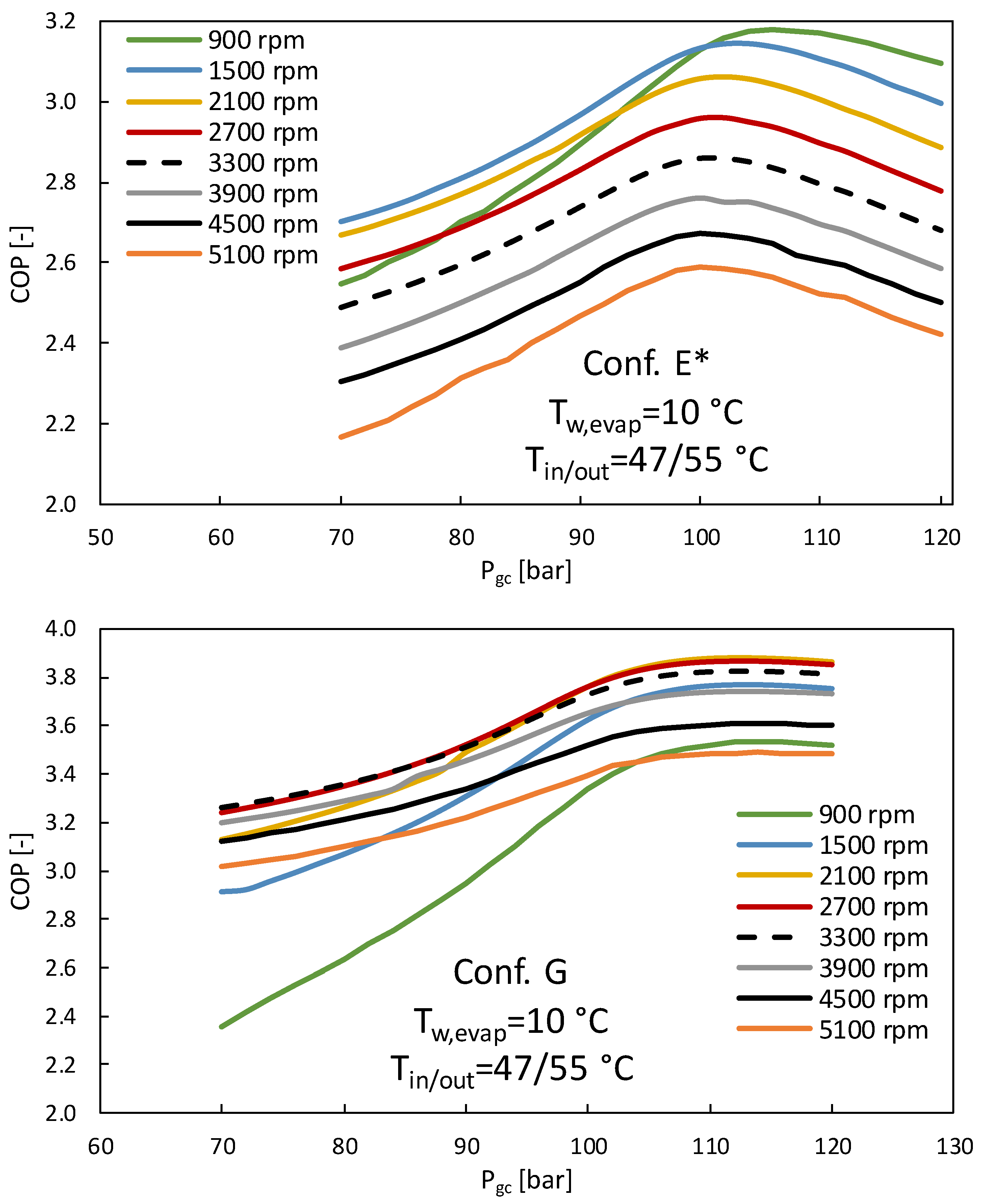
  • Water splitting strategy with a CO2 cycle with DMS with the DMS evaporator located downstream the IHX. This configuration was denoted as Conf. E*. Note that in this case the water flow to be heated is divided into two different streams, one sent to the condenser of the DMS cycle and the other to the gas cooler. Conf. E corresponds to the case where no IHX is used.
  • Finally, let us denote as Conf. F the configuration presented in Figure 3 which refers to a water splitting strategy proposed by Yang et al. in [30] without IHX and Conf. G corresponds to the same case with IHX (also presented in Figure 3).
The characteristics of the components modeled are those presented in Table 1. The evaporator, compressor, gas cooler, and IHX are plate heat exchangers. In the case of the CO2 cycle, they correspond to the actual elements of the CO2 heat pump used in the experimental rig. Table 2 shows a comparison of the characteristics of the different configurations studied.
Under these conditions the basic equations governing the numerical model are:
For the expansion valves:
h i n = h o u t
i n = o u t
where h represents enthalpy,   mass flow rate, and the subscripts “in”, “out” the evaluation of the variables and properties at the inlet and the outlet of the control volume of the element. For the IHX of the CO2 cycle, at the low pressure and high pressure side it is imposed the mass conservation principle (Equation (2)). In this case, the energy conservation implies the coupling between high and low pressure sides:
h i n h o u t h i g h p r e s = h o u t h i n l o w p r e s
where the subscripts “low-pres” and “high-pres” correspond to the low and high pressure sides of the IHX. For the heat exchanger coupling the CO2 and the R1234yf cycle, both at the CO2 or R1234yf it is imposed the mass conservation (Equation (2)) and the energy conservation principle, which in this case implies:
h i n h o u t C O 2 · C O 2 = R 1234 y f · h o u t h i n R 1234 y f
where the subscripts “CO2” and “R1234yf” correspond to the CO2 or R1234yf sides of the heat exchangers. For the evaporators or condensers of CO2 or R1234yf cycles when they are coupled to a water flow, it is imposed the mass conservation at the refrigerant and water sides following Equation (2). In this case, the energy conservation equations at the condensers or gas-cooler read:
h i n h o u t C O 2 · C O 2 = w a t e r · h o u t h i n w a t e r
h i n h o u t R 1234 y f · R 1234 y f = w a t e r · h o u t h i n w a t e r
and in the evaporators:
h i n h o u t w a t e r · w a t e r = C O 2 · h o u t h i n C O 2
h i n h o u t w a t e r · w a t e r = R 1234 y f · h o u t h i n R 1234 y f
where the subscript “water” refers to the water flow side of the heat exchanger. As for the equations describing the performance of the compressors of CO2 and R1234yf cycles they can be written as:
m ˙   = C 1 + ρ a ρ r · C 2 · T e v + C 3 · P o u t + C 4 · T e v 2 + C 5 · T e v · P o u t + C 6 · P o u t 2 + C 7 · T e v 3 + C 8 · P o u t · T e v 2 + C 9 · T e v · P o u t 2 + C 10 · P o u t 3
W ˙   = C 1 + ρ a ρ r · C 2 · T e v + C 3 · P o u t + C 4 · T e v 2 + C 5 · T e v · P o u t + C 6 · P o u t 2 + C 7 · T e v 3 + C 8 · P o u t · T e v 2 + C 9 · T e v · P o u t 2 + C 10 · P o u t 3 ,
where W ˙   denotes the compressor power demand, Ci is compressor coefficient following ANSI/AHRI Standard 540–2015, Pout the discharge pressure and Tev the evaporation temperature, ρr the density of the refrigerant at rated conditions (, in kg·m−3), and ρa the density of the refrigerant at compressor suction.
In this work, it is considered that the COP of the system can be obtained from:
C O P = q g c + q c o n d w c + w c 2
where qgc is the specific heat at the gas cooler, qcond is the specific heat at the condenser of the DMS cycle, and wc are the specific works at the compressors.
The refrigerant mass flow rate at the DMS cycle was estimated from Equation (4) as:
R 1234 y f = C O 2 · Δ h C O 2 Δ h R 1234 y f
where Δ h C O 2 and Δ h R 1234 y f are respectively the enthalpy change of CO2 and R1234yf at the heat exchanger acting as CO2 cycle subcooler and R1234yf cycle evaporator.
The numerical model assumes that all the energy input is actually turned into useful work that goes to the refrigerant. As previously said, all expansion devices are modeled as isenthalpic, and all heat exchangers have been modeled by deriving correlations for the evaporation/condensation pressure and heat transfer rate. In order to obtain those correlations, two different strategies were used. For the DMS cycle condenser, since it is a conventional subcritical water/refrigerant plate heat exchanger, a commercial software called IMST-ART [35] was used to obtain condensation pressure and heat transfer rate. For the case of the DMS evaporator a cell-by-cell discretization model also developed in MATLAB was used.
The procedure used to obtain the correlations of the evaporation pressure, condensation pressure, and heat transfer rates was similar in all those cases. First, a matrix of 16,800 different input data that correspond to the combination of different realistic conditions of the CO2 heat-pump experimental rig used in [2,23,24] was defined. To obtain these combinations, different inlet temperatures of the water at the evaporator of the CO2 cycle (between 10 and 30 °C) and at the CO2 gas-cooler (between 30 and 55 °C) with different temperature lifts at those heat exchangers as well as at the condenser of the R1234yf cycle were considered. Moreover, different superheating and subcooling degrees were considered to reach a total of 16,800 different combinations that could be repeated experimentally at the experimental rig of the lab. As said before, these input data fed the MATLAB and IMST-ART models to obtain the correlations of the evaporation pressure, condensation pressure, and heat transfer rates.
Once all the components of the DMS cycle were modeled, they were joined in a model for the global DMS- CO2 cycle built up in MATLAB. In this case, a total of 5850 different input conditions were considered. They were obtained by combining different water flow rates (between 800 and 1600 kg/h) as well as different gas cooler pressure levels (between 70 and 120 bar). A superheat of 5 K was imposed in both evaporators and no subcooling was set at the R1234yf condenser.
As an example, Figure 5 shows the thermodynamic temperature (T)-entropy (s) diagrams of auxiliary cycle and CO2 cycle for 2 DMS configurations:

3. Results and Discussion

Figure 6 shows the evolution of the global COP of the system as a function of the gas cooler pressure in the range from 60 to 130 bars for all the configurations studied with different heated water inlet/outlet temperatures and a fixed water inlet temperature of 10 °C at the evaporator. The water mass flow rate at the evaporator was 0.33 kg·s−1 for all of the cases. The comparison shows that depending on the coupling strategy between the DMS cycle and the CO2 heat pump, optimal COP values obtained can vary up to 30% whereas the optimal operating pressure of the CO2 cycle can vary up to 8%.
In light of the results of Figure 6, it is found that in all the cases the configuration with a DMS-CO2 cycle with IHX and water splitting (Conf. G) is the one that provides the best COP values which rounds between 3.3 and 5.1 for the different temperature heating ranges. Note that for the case of swimming pool water heating (25/30 °C), the same configuration but without IHX has a similar performance. In the case of working under the gas cooler pressure that provides the maximum COP, the configurations proposed by [30] are the only ones that provide better COP values than the base cycle with IHX and without DMS. In fact, the improvement obtained with the use of a DMS + IHX and a water splitting strategy with respect to the base case is 5.7% for the case of 25/30 °C, 13.7% for the case of 30/35 °C, 25% for the case of 40/45 °C, 21.3% for the case of 47/55 °C, and 21.4% for the case of 55/65 °C. It is also worth noting that the optimal gas cooler pressure for the base cycle and the configurations proposed by Yang et al. are similar, therefore those configurations do not help to reduce the operative pressures of the system. Finally, it is noteworthy that in many cases, the DMS cycle without IHX (Figure 2) provides the lowest COP values.
Figure 7 shows the influence of the inlet water temperature at the evaporator for the case of configurations Conf. E* and Conf. G. As shown, for the configuration with a water splitting strategy with the DMS evaporator located downstream the IHX (Conf. E*) the COP increases as the inlet water temperature at the evaporator increases, whereas for the case of a configuration with a water splitting strategy but for the case of DMS cycle combined with IHX in a transcritical CO2 heat pump with a water stream splitting strategy proposed by [30] (Conf. G) it is more convenient to use low inlet water temperatures at evaporator when gas cooler working pressure is below 80 bars.
The next figures show the influence of some key design parameters for the case of 47/55 °C heating conditions. These parameters are the compressor speed (Figure 8) and the ratio of water to be heated derived to the gas cooler and DMS condenser (Figure 9).
Figure 8 shows the influence of the compressor’s angular velocity in rpm for the case of configurations E* and Conf. G and an evaporator inlet water temperature of 10 °C. As shown, different tendencies are found depending on the design configuration. For the case of Conf. E* (Figure 4 down), the lowest compressor speed (900 rpm) was found to be the best one to reach the highest COP values of the system, whereas, for the configuration presented in Figure 3 with IHX (Conf. G), the optimal compressor speed was found to be in the range of 2100 rpm. It is also worth noting that for this last configuration, the maximum COP values are obtained in a wide range of working gas cooler pressure operating conditions between 100 and 120 bars.
Finally, Figure 9 permits to select the criteria of the splitting strategy between the gas cooler and the DMS condenser of the water to be heated. The figure shows different ratios of the water sent to the gas cooler and to the DMS condenser for the configurations E* and G, for the case of 47 °C/55 °C heating temperature range, an inlet water temperature to the evaporator of 10 °C. As shown, for a strategy based on water splitting with the DMS evaporator located downstream the IHX (Conf. E*), there is nearly no influence of share ratio, whereas for the case of the configuration presented in Figure 3 with IHX(Conf. G) it is clearly better to send a higher percentage of the water to the DMS condenser. In fact, the best configuration found is the one where 15% of the water flow is sent to the gas cooler and 85% of the water flow is sent to the DMS condenser (which is the case 15/85 in Figure 9.down).
Regarding the optimal design, from a thermodynamic point of view, it is generally expected that an advanced cycle design leads to higher efficiencies. This is not always the case during a design process. Moreover, advanced designs imply that more components are needed which probably will increase the complexity and costs of the device. Thus, designers and end-users must evaluate these key issues in order to balance and choose the optimal final solution. In order to discuss this issue, a simple evaluation of the complexity of the system can be defined based on the number of representative components in the system. Figure 10 shows the evolution of the maximum COP obtained as a function of dimensionless number of components (which is used here as a rough estimator of the complexity index) for space heating applications (Tin/Tout = 47 °C/55 °C and 55 °C/65 °C) as well as for swimming pool water heating applications (Tin/Tout = 25 °C/30 °C). As shown, the highest COPs are obtained for a configuration with the highest complexity index (Conf. G). However, the configuration with the lower complexity index (Conf. A) is the third one with the best COP. Thus, in this case, there is not a clear correlation between the maximum COP and the complexity index of the design. Regarding the influence of the water inlet/outlet temperature range, it is found that the best options are Conf. G and F for the lower temperature range (i.e., case of water pool heating in swimming pool applications Tin/Tout 25 °C/35 °C). However, as the temperature level considered increases, the maximum COP decreases, and the COP difference between Conf. G and Conf. F increases. Note that the maximum COP obtained with Conf. G in the case of Tin/Tout 47 °C/55 °C (i.e., space heating applications) is nearly the same as the one of Conf. E*, C,C*, and D* in the case of Tin/Tout 25 °C/35 °C (i.e., swimming pool applications). Moreover, as the temperature level decreases, the maximum COP obtained with Conf. A approaches the one of Conf. G.

4. Conclusions

In this work, the results of a numerical study are presented where different configurations of DMS cycles coupled with a water source, transcritical CO2 heat pump are used with or without IHX to improve the energy efficiency of heat pump systems for space heating and/or swimming pool water heating applications. For that purpose, a thermodynamic model was developed in MATLAB and used to simulate different operating conditions under the European standard 14,511 [32]. Results show that a configuration based on splitting the water flow to be heated into the DMS condenser and the gas cooler (Figure 3, named as Conf. G) is the best option for this type of applications for all the inlet/outlet water temperature ranges studied: 25/30 °C, 30/35 °C, 40/45 °C, 47/55 °C, and 55/65 °C. The improvement in the maximum COP values obtained with this configuration range between 5% and 25% depending on the water temperature range considered. Moreover, the work highlight other key specifics:
  • As the improvement obtained with a water splitting strategy with DMS and IHX (Figure 3) with respect to the base cycle with IHX (Figure 1) depends on the temperature range considered, it is highly recommended to evaluate the application when selecting the configuration to be used. For the case of space heating applications with temperature ranges of 40/45 °C, this DMS option provides an improvement of 25% in the optimal COP values reached by the system. However, in the case of water pool heating applications in indoor swimming pools (25/30 °C), the improvement is reduced to 5%.
  • When the configurations of Figure 3 (Conf. G and F) are not considered, the base CO2 cycle with IHX but without DMS is the best option when the system works under optimal gas cooler pressure conditions.
  • When all the coupling strategies between the DMS cycle and the CO2 heat pump are compared, optimal COP values obtained can vary up to 30% whereas the optimal operating pressure of the CO2 cycle can vary up to 8%.
  • Regarding key design parameters, an optimal compressor speed of 2100 rpm was found for Conf. G. (i.e., configuration of Figure 3 with IHX). Moreover, the optimal water flow splitting strategy for this configuration was the case of heating 15% of the water flow at the gas cooler and 85% of the water flow at the DMS condenser.
Future work will face the application of the optimal strategies found at lab scale and its testing in space heating applications in an actual building and/or swimming pool.

Author Contributions

Conceptualization, F.I.-G. and J.R.G.-C.; methodology, F.I.-G.; software, F.I.-G., R.A.O.-M.; validation, F.I.-G., J.R.G.-C. and R.A.O.-M.; formal analysis, F.J.S.-V.; investigation, F.I.-G., J.R.G.-C.; resources, J.R.G.-C.; data curation, F.J.S.-V.; writing—original draft preparation, F.J.S.-V.; writing—review and editing, F.J.S.-V.; visualization, F.J.S.-V.; supervision, J.R.G.-C.; project administration, J.R.G.-C.; funding acquisition, F.I.-G. All authors have read and agreed to the published version of the manuscript.

Funding

This research was funded by the Spanish Ministry of Science and Innovation under Project TED2021-131173B-I00 and the NextGenerationEU recovery plan.

Institutional Review Board Statement

Not applicable.

Informed Consent Statement

Not applicable.

Data Availability Statement

Not applicable.

Conflicts of Interest

The authors declare no conflict of interest.

References

  1. Nekså, P.; Rekstad, H.; Zakeri, G.; Schiefloe, P. CO2 heat pump water heater: Characteristics, system, design and experimental results. Int. J. Refrig. 1998, 21, 172–179. [Google Scholar] [CrossRef]
  2. Velasco, F.; Haddouche, M.; Illán-Gómez, F.; García-Cascales, J. Experimental characterization of the coupling and heating performance of a CO2 water-to-water heat pump and a water storage tank for domestic hot water production system. Energy Build. 2022, 265, 112085. [Google Scholar] [CrossRef]
  3. Hepbasli, A.; Biyik, E.; Ekren, O.; Gunerhan, H.; Araz, M. A key review of wastewater source hat pump (WWSHP) system. Energy Convers. Manag. 2014, 88, 700–722. [Google Scholar] [CrossRef]
  4. Culha, O.; Gunerhan, H.; Biyik, E.; Ekren, O.; Hepbasli, A. Heat exchanger applications in wastewater source heat pumps for buildings: A key review. Energy Build. 2015, 104, 215–232. [Google Scholar] [CrossRef]
  5. Shen, C.; Lei, Z.; Wang, Y.; Zhang, C.; Yao, Y. A review of the current research and application of wastewater source heat pumps in China. Therm. Sci. Eng. Prog. 2018, 6, 140–156. [Google Scholar] [CrossRef]
  6. Mazhar, A.R.; Liu, S.; Shukla, A. A Key Review of Non-Industrial Greywater Heat Harnessing. Energies 2018, 11, 386. [Google Scholar] [CrossRef] [Green Version]
  7. Shen, C.; Jiang, Y.; Yao, Y.; Wang, X. An experimental comparison of two heat exchangers used in wastewater source heat pump: A novel dry-expansion shell-and-tube evaporator versus a conventional immersed evaporator. Energy 2012, 47, 600–608. [Google Scholar] [CrossRef]
  8. Baek, N.; Shin, U.; Yoon, J. A study on the design and analysis of a heat pump heating system using wastewater as a heat source. Sol. Energy 2005, 78, 427–440. [Google Scholar] [CrossRef]
  9. Gu, Y.; Deng, H. The Feasibility Analysis of Wastewater Source Heat Pump Using the Urban Wastewater Heat. Res. J. Appl. Sci. Eng. Technol. 2012, 4, 3501–3504. [Google Scholar]
  10. Tassou, S. Heat recovery from sewage effluent using heat pumps. Heat Recover. Syst. CHP 1988, 8, 141–148. [Google Scholar] [CrossRef]
  11. Ni, L.; Lau, S.; Li, H.; Zhang, T.; Stansbury, J.; Shi, J.; Neal, J. Feasibility study of a localized residential grey water energy-recovery system. Appl. Therm. Eng. 2012, 39, 53–62. [Google Scholar] [CrossRef]
  12. Zhong, Z.W.; Li, J.X. Sewage Heat Source Pump System’s Application Examples and Prospect Analysis in China. In Proceedings of the International Refrigeration and Air Conditioning Conference, West Lafayette, IN, USA, 12–15 July 2004; Paper 734. Available online: http://docs.lib.purdue.edu/iracc/734 (accessed on 1 June 2022).
  13. Liu, Z.; Ma, L.; Zhang, J. Application of a heat pump system using untreated urban sewage as a heat source. Appl. Therm. Eng. 2014, 62, 747–757. [Google Scholar] [CrossRef]
  14. Kahraman, A.; Çelebi, A. Investigation of the Performance of a Heat Pump Using Waste Water as a Heat Source. Energies 2009, 2, 697–713. [Google Scholar] [CrossRef]
  15. Chao, S.; Yiqiang, J.; Yang, Y.; Shiming, D.; Xinlei, W. A field study of a wastewater source heat pump for domestic hot water heating. Build. Serv. Eng. Res. Technol. 2012, 34, 433–448. [Google Scholar] [CrossRef]
  16. Coşkun, S.; Motorcu, A.R.; Yamankaradeniz, N.; Pulat, E. Evaluation of control parameters’ effects on system performance with Taguchi method in waste heat recovery application using mechanical heat pump. Int. J. Refrig. 2012, 35, 795–809. [Google Scholar] [CrossRef]
  17. Shen, C.; Yang, L.; Wang, X.; Jiang, Y.; Yao, Y. An experimental and numerical study of a de-fouling evaporator used in a wastewater source heat pump. Appl. Therm. Eng. 2014, 70, 501–509. [Google Scholar] [CrossRef]
  18. Hervas-Blasco, E.; Navarro-Peris, E.; Barcelo-Ruescas, F.; Corberán, J.M. Improved water to water heat pump design for low-temperature waste heat recovery based on subcooling control. Int. J. Refrig. 2019, 106, 374–383. [Google Scholar] [CrossRef]
  19. Nehm, G.; Palandre, L.; Clodic, D.F. High Efficiency Heat Pump for Domestic Hot Water Generation. In Proceedings of the International Refrigeration and Air Conditioning Conference, West Lafayette, IN, USA, 14–17 July 2008; Paper 953. Available online: http://docs.lib.purdue.edu/iracc/95 (accessed on 3 June 2022).
  20. Wang, H.; Wang, Q.; Chen, G. Experimental performance analysis of an improved multifunctional heat pump system. Energy Build. 2013, 62, 581–589. [Google Scholar] [CrossRef]
  21. Yamankaradeniz, N.; Coşkun, S.; Muhiddin, C.A.N. Comparison Between Conventional System and Heat Pump for Energy Saving in Textile Industry by Utilizing Waste Heat. J. Uludag Univ. Fac. Eng. Archit. 2007, 12, 115–124. [Google Scholar] [CrossRef]
  22. Otón-Martínez, R.A.; Illán-Gómez, F.; García-Cascales, J.R.; Velasco, F.; Haddouche, M.R. Impact of an internal heat exchanger on a transcritical CO2 heat pump under optimal pressure conditions. Appl. Therm. Eng. 2022, 215, 118991. [Google Scholar] [CrossRef]
  23. Illán-Gómez, F.; Sena Cuevas, V.F.; García-Cascales, J.R.; Velasco, F.J.S. Analysis of the optimal gas cooler pressure of a CO2 heat pump with gas bypass for hot water generation. Appl. Therm. Eng. 2021, 182, 116110. [Google Scholar] [CrossRef]
  24. Illán-Gómez, F.; Sena Cuevas, V.F.; García-Cascales, J.R.; Velasco, F.J.S. Experimental and numerical study of a CO2 water-to-water heat pump for hot water generation. Int. J. Refrig. 2021, 132, 30–44. [Google Scholar] [CrossRef]
  25. Nebot-Andrés, L.; Calleja-Anta, D.; Sánchez, D.; Cabello, R.; Llopis, R. Experimental assessment of dedicated and integrated mechanical subcooling systems vs parallel compression in transcritical CO2 refrigeration plants. Energ. Conv. Manag. 2022, 252, 115051. [Google Scholar] [CrossRef]
  26. Dai, B.; Zhao, X.; Liu, S.; Yang, Q.; Zhong, D.; Hao, Y.; Hao, Y. Energetic, exergetic and exergoeconomic assessment of transcritical CO2 reversible system combined with dedicated mechanical subcooling (DMS) for residential heating and cooling. Energy Convers. Manag. 2020, 209, 112594. [Google Scholar] [CrossRef]
  27. Dai, B.; Qi, H.; Liu, S.; Zhong, Z.; Li, H.; Song, M.; Ma, M.; Sun, Z. Environmental and economical analyses of transcritical CO2 heat pump combined with direct dedicated mechanical subcooling (DMS) for space heating in China. Energy Convers. Manag. 2019, 198, 111317. [Google Scholar] [CrossRef]
  28. Dai, B.; Qi, H.; Qi, H.; Liu, S.; Ma, M.; Zhong, Z.; Li, H.; Song, M.; Sun, Z. Evaluation of transcritical CO2 heat pump system integrated with mechanical subcooling by utilizing energy, exergy and economic methodologies for residential heating. Energy Convers. Manag. 2019, 192, 202–220. [Google Scholar] [CrossRef]
  29. Wang, G.-B.; Zhang, X.-R. Thermoeconomic optimization and comparison of the simple single-stage transcritical carbon dioxide vapor compression cycle with different subcooling methods for district heating and cooling. Energy Convers. Manag. 2019, 185, 740–757. [Google Scholar] [CrossRef]
  30. Yang, D.; Song, Y.; Cao, F.; Jin, L.; Wang, X. Theoretical and experimental investigation of a combined R134a and transcritical CO2 heat pump for space heating. Int. J. Refrig. 2016, 72, 156–170. [Google Scholar] [CrossRef]
  31. Qi, P.-C.; He, Y.-L.; Wang, X.-L.; Meng, X.-Z. Experimental investigation of the optimal heat rejection pressure for a transcritical CO2 heat pump water heater. Appl. Therm. Eng. 2013, 56, 120–125. [Google Scholar] [CrossRef]
  32. EN 14511-2; Air Conditioners, Liquid Chilling Packages and Heat Pumps for Space Heating and Cooling and Process Chillers, with Electrically Driven Compressors—Part 2: Test Conditions. European Committee for Standardization: Brussels, Belgium, 2018.
  33. ANSI/AHRI 540; Standard for Performance Rating of Positive Displacement Refrigerant Compressors and Compressor Units. ANSI/AHRI: Otawa, Canada, 2015; pp. 1–19.
  34. Dabiri, A.E.; Rice, C.K. Compressor-simulation model with corrections for the level of suction gas superheat. ASHRAE Trans. 1981, 87, 771–782. [Google Scholar]
  35. IMST-ART. A Simulation Tool to Assist the Selection, Design and Optimization of Refrigeration Equipment and Components; Instituto de Ingeniería Energética, Technical University of Valencia: Valencia, Spain, 2021; Available online: http://www.imst-art.com/ (accessed on 10 May 2022).
Figure 1. Basic water source, transcritical CO2 heat pump with IHX configuration analyzed for hot water generation.
Cleantechnol 04 00074 g001
Figure 2. DMS cycle combined with a transcritical CO2 heat pump without IHX.
Cleantechnol 04 00074 g002
Figure 3. DMS cycle combined with a transcritical CO2 heat pump with a water stream splitting strategy proposed by [30].
Cleantechnol 04 00074 g003
Figure 4. CO2-DMS configurations analyzed for space heating: water heating with condenser and gas cooler in series with IHX (top-left) and without IHX (top-right), water splitting strategy in a DMS with IHX (down). * indicates a different direction of the water flow within the water lines.
Cleantechnol 04 00074 g004
Figure 5. Thermodynamic diagrams of auxiliary cycle and CO2 cycle for 2 DMS configurations: (Up) Configuration C. (Down) Configuration E.
Cleantechnol 04 00074 g005aCleantechnol 04 00074 g005b
Figure 6. COP vs. gas cooler pressure for the configurations considered for space heating at (a) 30/35 °C; (b), 40/45 °C; (c) 47/55 °C; (d) 55/65 °C and (e) swimming pool water heating at 25/30 °C. * indicates a different direction of the water flow within the water lines.
Cleantechnol 04 00074 g006aCleantechnol 04 00074 g006bCleantechnol 04 00074 g006c
Figure 7. Influence of the evaporator inlet water temperature on the COP as a function of the gas cooler pressure for the case 47/55 °C for configurations Conf. E* (up) and Conf. G (down).
Cleantechnol 04 00074 g007
Figure 8. COP vs. gas cooler pressure as a function of the compressor speed for the case 47/55 °C for configurations Conf. E* (up) and Conf. G (down).
Cleantechnol 04 00074 g008
Figure 9. Influence of the ratio of the heating water sent to the DMS condenser and gas cooler on the COP of the system for configurations Conf. E* (up) and Conf. G (down).
Cleantechnol 04 00074 g009
Figure 10. Maximum COP as a function of complexity index for space heating applications (47 °C/55 °C and 55 °C/65 °C) as well as for swimming pool water heating applications (25 °C/30 °C).
Cleantechnol 04 00074 g010
Table 1. Characteristics of the elements of the cycles considered.
EquipmentTechnical Info
CO2 cycleEvaporatorA = 0.552 m2
Compressor V ˙ = 1.46   m 3 · h 1
Gas coolerA = 1.31 m2
IHXA = 0.082 m2
Back Pressure Valvekv = 0.042 m3·h−1
Electronic Expansion Valvekv = 0.18 m3·h−1
SubcoolerA = 0.738 m2
R1234yf cycleEvaporator
Compressor V ˙ = 5.76   m 3 · h 1
CondenserA = 0.322 m2
Electronic Expansion Valvekv = 0.164 m3·h−1
Table 2. Characteristics of the configurations studied.
ConfigurationWater Heating ConfigurationIHX
CO2 cycle (Conf. A)water heats up through gas coolerX
DMS CO2 cycle+ R1234yf cycle (Conf. B)water heats up through condenser and gas cooler in series -
DMS CO2 cycle+ R1234yf cycle (Conf. C&C*)water heats up through condenser and gas cooler in series with IHX located between evaporator and liquid receiver X
DMS CO2 cycle+ R1234yf cycle (Conf. D&D*)water heats up through condenser and gas cooler in series with IHX between gas cooler and evaporatorX
DMS CO2 cycle+ R1234yf cycle (Conf. E)splitting strategy: water heats up through condenser and gas cooler in parallel-
DMS CO2 cycle+ R1234yf cycle (Conf. E*)splitting strategy: water heats up through condenser and gas cooler in parallelX
Indirect DMS CO2 cycle+ R1234yf cycle (Conf. F)splitting strategy: water heats up through condenser and evaporator + gas cooler in parallel-
Indirect DMS CO2 cycle+ R1234yf cycle (Conf. G)splitting strategy: water heats up through condenser and evaporator + gas cooler in parallelX
Publisher’s Note: MDPI stays neutral with regard to jurisdictional claims in published maps and institutional affiliations.

