1. Introduction
The continuous use of fossil fuels, especially in recent decades, has led to various environmental issues, such as global warming and air pollution. In addition, energy crisis has affected the world economy to a great extent [
1]. Considering that vehicles consume the overwhelming majority of fossil fuels used in the world, an effort has been made over the last few years to change the scene so that vehicles are as least-polluting as possible. This can be performed by the use of vehicle electrification technologies, including electric vehicles (EVs) and hybrid electric vehicles (HEVs), on the basis that they use electricity produced from renewable energy sources [
2,
3,
4]. However, EVs are a major technological challenge for power grids, since passive elements constitute a new kind of cargo. Therefore, a large number of electric vehicles can appreciably burden the grid and adversely affect its smooth operation [
5,
6].
In general, EVs are classified into three major categories according to the way and the place of production of electricity ([
7]): a. Vehicles using continuous power supply from an external power source, such as an overhead supply line. Unfortunately, these vehicles have a major limitation of having to move on specific routes in order to maintain continuous external electricity power supply for their operation. b. Vehicles based on the storage of electricity supplied from an external source. In order to save energy, these vehicles use batteries or supercapacitors. c. Vehicles that produce electricity within the vessel itself to meet their needs. These include electric hybrid cars that use thermal motors in series or parallel to electric motors, as well as EVs with fuel cells. Another separation of EVs is based on the source of energy type [
8].
In this context, two major categories can be classified: a. Battery electric vehicles (BEV), and b. Hybrid electric vehicles (HEV). BEVs use batteries as a source of energy and they are also called “green vehicles, or clean vehicles, or eco-friendly vehicles” because they have zero emissions. In order to cover a travel distance, they are equipped with larger storage batteries than HEVs. However, the limited traveling distance of BEVs is an important drawback because it is often necessary to recharge the battery by connecting to an external power source (in city cars, autonomy starts from 100 to 120 km and reaches 500 km or more in high power cars—Tesla Model). A HEV is classified as a car that uses two or more different technologies to achieve its movement. These technologies usually include the classic internal combustion engine and a more “mild” environmentally-friendly technology, usually an electric motor. However, the electric motor is used as a supplementary power source in cases where the HEV requires more power.
It is apparent from the above that proper energy management is of vital importance for the smooth operation of EVs. A challenging research field includes the design and implementation of efficient charging schemes that ensure fast and reliable EV charging in order to increase vehicle autonomy. In this concept, the vehicle-to-grid (V2G) approach aims to optimize the way we transport, use, and produce electricity by turning electric cars into “virtual power plants” [
9]. V2G technology refers to a bi-directional flow system operation, in which plug-in battery electric vehicles communicate with a recipient and allow the reciprocal flow between the EV and an electric grid [
10,
11]. Under this relatively new concept, electric cars would store and dispatch electrical energy stored in networked vehicle batteries which together act as one collective battery fleet for “peak shaving” (sending power back to the grid when demand is high) and “valley filling” (charging at night when demand is low) [
12,
13,
14]. V2G technology also improves stability and reliability of the grid, regulates the active power, and provides load balancing by valley fillings. These features enable better ancillary services, voltage control, frequency regulation, maintained peak power, and lead overall to a reduction of electric costs. In addition, owing to the inherent high mobility of EVs, flexible and timely on-demand response services against EV mobility in the V2G system must be provided [
15]. To this end, several solutions have been proposed for integrating V2G technologies in fifth generation (5G) emerging wireless infrastructures, in order for the mobile user to experience a unified approach on application management (e.g., real time navigation with traffic update and potential alarms regarding the energy autonomy of the EV) [
16,
17,
18]. Additional research areas in EVs also include the design and deployment of self-driving objects, where efficient wireless coverage and zero latency are of utmost importance [
19].
In this article, the current state of the art in EVs along with various technological aspects, such as charging techniques and wireless power transfer are presented and analyzed. Emerging issues, such as connection of EVs to SEGs and autonomous driving requirements, are analyzed as well. The rest of this article is organized as follows: HEVs are presented in more detail in
Section 2, while in
Section 3 an analysis on charging technologies and related standards is provided. Wireless charging techniques (WCTs) are presented in
Section 4, while vehicle to grid (V2G) design and implementation issues are discussed in
Section 5. Energy management issues are presented in
Section 6, while in
Section 7 autonomous driving issues are outlined, in conjunction with recent advances in 5G networks deployment. Finally, concluding remarks are provided in
Section 8.
2. Hybrid Electric Vehicles
HEVs can be graded according to their degree of hybridization, which is defined as the ratio resulting from dividing the power of the electric motor (or motors) into the power of the internal combustion engine. In this context, the following categories arise: cases A, B, C. Moreover, and additional separation is made on the mode in which energy converters are combined to move the vehicle. In this case, corresponding categories are cases D, E, F, G, H [
20,
21]. In the following subsections, the basic types of HEVs are described.
2.1. Micro Hybrid Stop-Start (μHV)
The micro-hybrids have relatively small electric motors (about 3 to 5 kW at 12V) which do not drive the vehicle but have the power to restart the internal combustion engine. This means that a micro-hybrid petrol vehicle can automatically shut off its engine when the vehicle is stationary (e.g., in traffic lights) and restarts as soon as the driver depresses the accelerator pedal without the need to use the starter, and often without the driver knowing that the engine has stopped. The electric motor of the vehicle is not intended to participate in propulsion of the vehicle. However, it is connected to the wheels of the vehicle so as to recover some of the kinetic brake energy, acting as a generator, and can replace the vehicle’s starter. μHV typically have a hybridization rate of 5%–10% with energy savings of about 3%–10% in city driving. The design of μHV is usually found in light vehicles and is most suitable for urban applications.
2.2. Mild Hybrid (MHV)
The ‘mild’ hybrid vehicles have a 7–15 kW and 60–200 V electric motor used to start the internal combustion engine and partly participate in the propulsion of the vehicle. The “mild” hybrids cannot operate solely with the motor since it is not connected to the drive. Instead, they offer additional power through the electric motor when required (e.g., at times of high acceleration). They also have the advantage of kinetic energy recovery through braking. The hybridization factor of mild hybrids is about 10%–30%. The size of the battery is larger than the corresponding one in the small hybrid. The energy saving on city driving is around 20%–30% [
22].
2.3. Full Hybrid (FHV)
In this category, the electric motor carries more than 25% of the power balance of the car. The power of the motor is about 30–50 kW at 200–600 V and is sufficient to drive the vehicle at low speeds and with low loads. When the power requirements increase, the internal combustion engine participates in the drive process on the wheels. Energy savings are now increased compared to the previous two cases and are in the range of 30%–50% [
22].
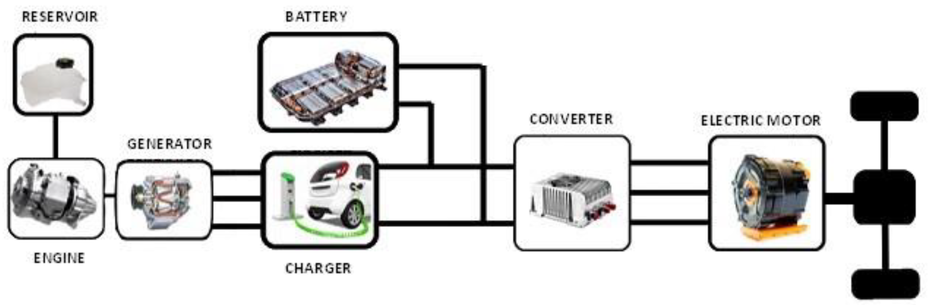
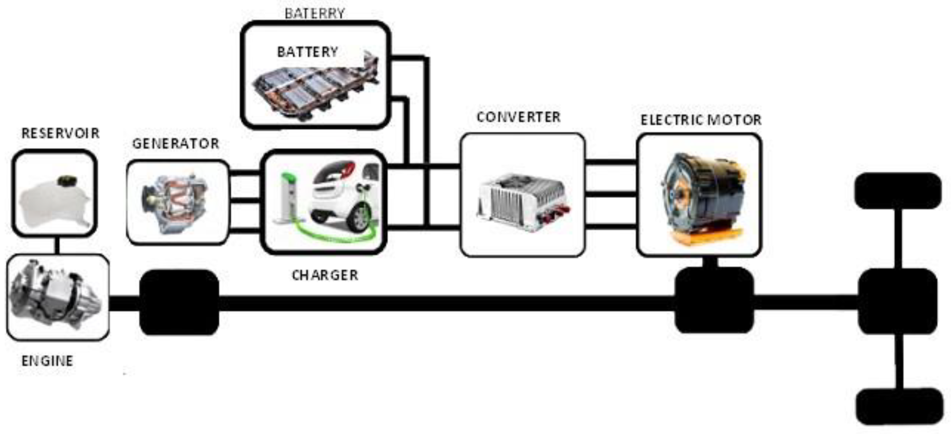
2.3.1. Series Hybrid EVs (SHEV)
The combination of thermal and electric motor in series is the simplest form of hybrid car (
Figure 1). For the vehicles in this category, only the drive is connected to the drive system. The motor is powered either by batteries or by a generator driven by the internal combustion engine. The generator feeds the electric motor when the traction load increases or charges the batteries when the load is small. However, there are certain disadvantages associated with SHEVs: (i) The generator and the motor are now separate parts, which in turn results in increased cost and reduced performance due to the presence of more individual systems [
23], (ii) The electric motor must be of high power to accommodate a high drag, such as climbing uphill.
2.3.2. Parallel Hybrid EVs (PHEV)
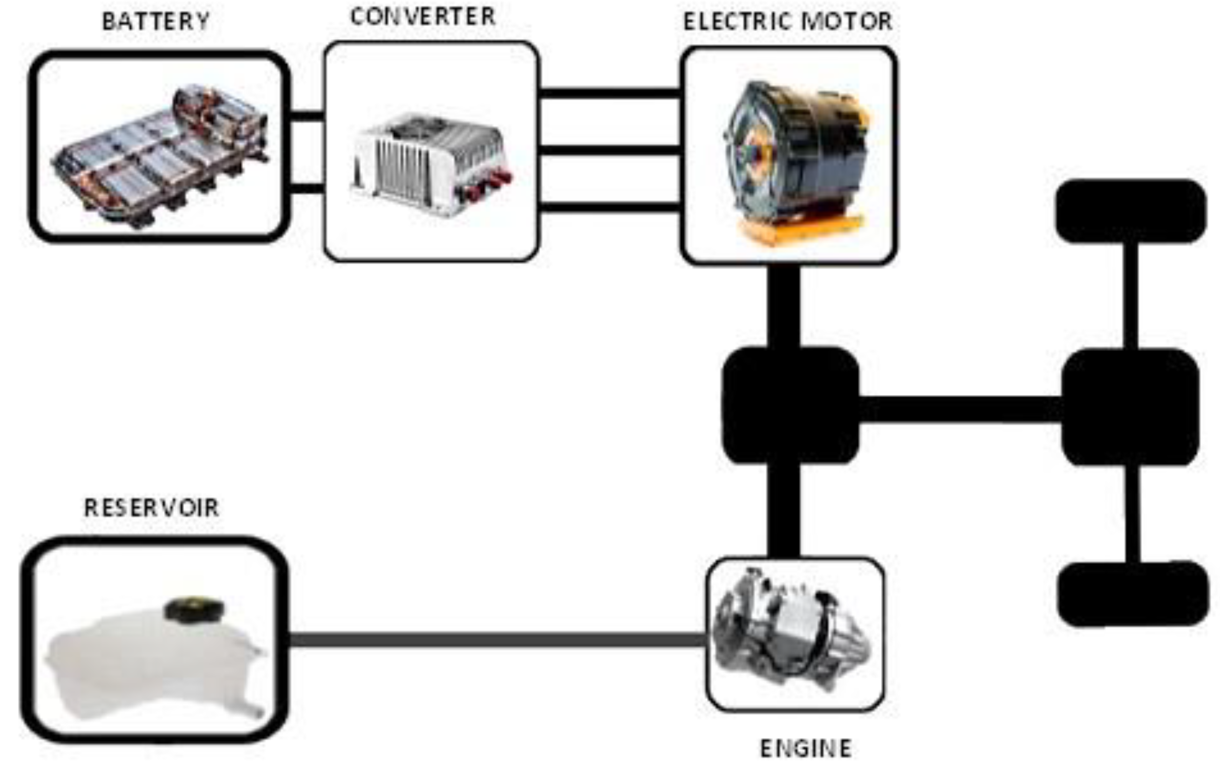
Parallel layout (
Figure 2) is the most common drive system topology in hybrid vehicles. In this type of vehicle, the internal combustion engine and the motor are directly connected to the drive system. Motion procedure can be described as follows: during low traction demand, the car is driven either by the motor or by the internal combustion engine alone. When only one of the two engines is operating, the other will be disconnected via a clutch. If demand increases then both engines help to drive the vehicle. Most PHEV designs combine the generator and the engine into one unit. PHEV uses smaller batteries than the other hybrids and need a smaller pull motor. The disadvantage of PHEV is its complex mechanical systems.
2.3.3. Series-Parallel Hybrid EVs (SPHEV)
The SPHEV system is a combination of the two above-mentioned devices. In the serial-parallel configuration, the internal combustion engine and the motor connected to the transmission system can propel the vehicle either together or separately. The gasoline engine can help drive the vehicle or charge the batteries through the generator connected to it. It is a solution, though much more complex and expensive. A disadvantage is that SPHEVs require very complex control systems.
2.3.4. Fuel Cell Hybrid EVs (FCHEV)
It is a hybrid type of car that looks like a SHEV (series), except that it uses a fuel cell (FC) HEV. A fuel cell is a chemical machine that generates electricity based on hydrogen and only emits water vapor. The principle of fuel cell operation is the reverse electrolysis process in which hydrogen and oxygen gases are combined to produce electricity with water and heat as byproducts. FCHEV technology has only been piloted in few vehicles, due to its high cost (hydrogen production is unprofitable and there are difficulties in transporting and distributing it).
2.3.5. Plug-In Hybrid Electric Vehicles (PHEV)
A PHEV (
Figure 3) is a hybrid vehicle in which the batteries can be recharged either by connecting the vehicle to an external power source either internally via the motor-driven generator or by braking as in standard HEVs. External electricity can come from the power grid, including domestic or autonomous systems or even from renewable energy sources. PHEVs have a lower electric range compared to typical HEVs per recharge if the battery is used but have a larger range in general because the motor-generator movement can help the system when the batteries are exhausted. Moreover, due to the large electric motor, PHEVs have a higher braking capacity compared to the traditional HEV. Other benefits of PHEVs include longer distance coverage than HEVs, low operating cost compared to a gasoline vehicle, while they are also environmentally friendly. The major drawbacks are still high costs and unavailability of fast charging stations.
5. V2G Technology
Through bi-directional power transfer, electrical power is taken from the grid or produced by photovoltaic panels and used to charge EVs connected to the system. As long as an EV is plugged in, the stored energy of the batteries can be fed back into the grid, to stabilize it in case of shortage or excess quantity. This is an integrated energy management philosophy, where the power grid distributes and receives energy stored in EV batteries via vehicle-to-grid or V2G technology and is designed to better manage overall power [
33]. Usually most cars are parked 90–95% of the time, charging the car in the evening, and power the grid, giving energy back, at peak times. V2G technology is useful because of a major weakness in the current power grid, which is the failure to store electricity and the use of these stocks to serve hours of increased demand. The amount of energy to be given back to the grid depends on the type and dimensions of the electric vehicle. For example, in the case of a battery-powered electric vehicle, the stored energy depends on the capacity of the batteries, and in the case of fuel cell use, the stored energy depends on the mass of the fuel (e.g., compressed hydrogen). Here we have economic benefits, both in terms of the power grid and money savings, that would be attributed to higher demand service solutions, as well, as on the owner-operator side of electric vehicles.
Two strategies are provided for loading and unloading V2G PEVs during system failures [
34]: In the first strategy, if the charging station (CS) is in the charging state of the car, then the charging of the PEVs stops and the available power from all the connected vehicles is used to supply power to the system. In the second strategy, as soon as a failure is detected in the system, the PEV charging stops. If the available power from vehicles connected to V2G mode (programmed discharge/V2G) is sufficient to restore energy to the system, PEVs without V2G function are disconnected from the system. If the power from V2G-connected vehicles is not enough, then vehicles simply plugged into the grid without V2G function are converted to V2G mode to fill the electricity demand gap. An actual implementation of V2G system is described in [
35].
In order for a vehicle to operate in V2G mode, there must be two conditions. The first is to have electronic power circuits that support V2G technology. The second requirement is to have a real-time communication with the network operator for power demand [
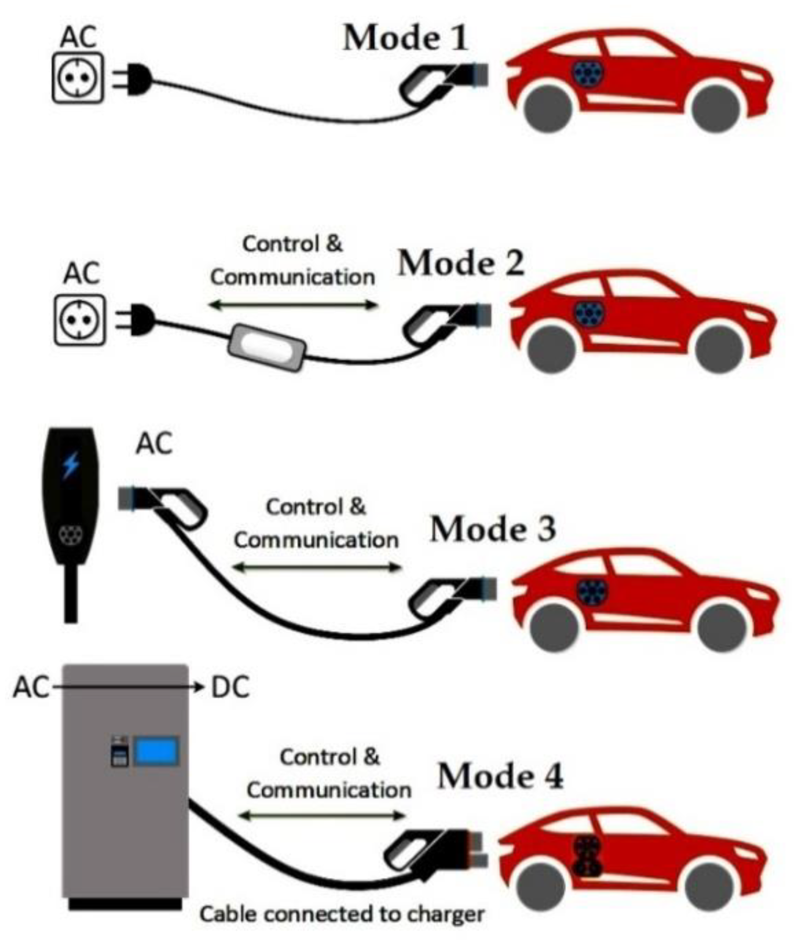
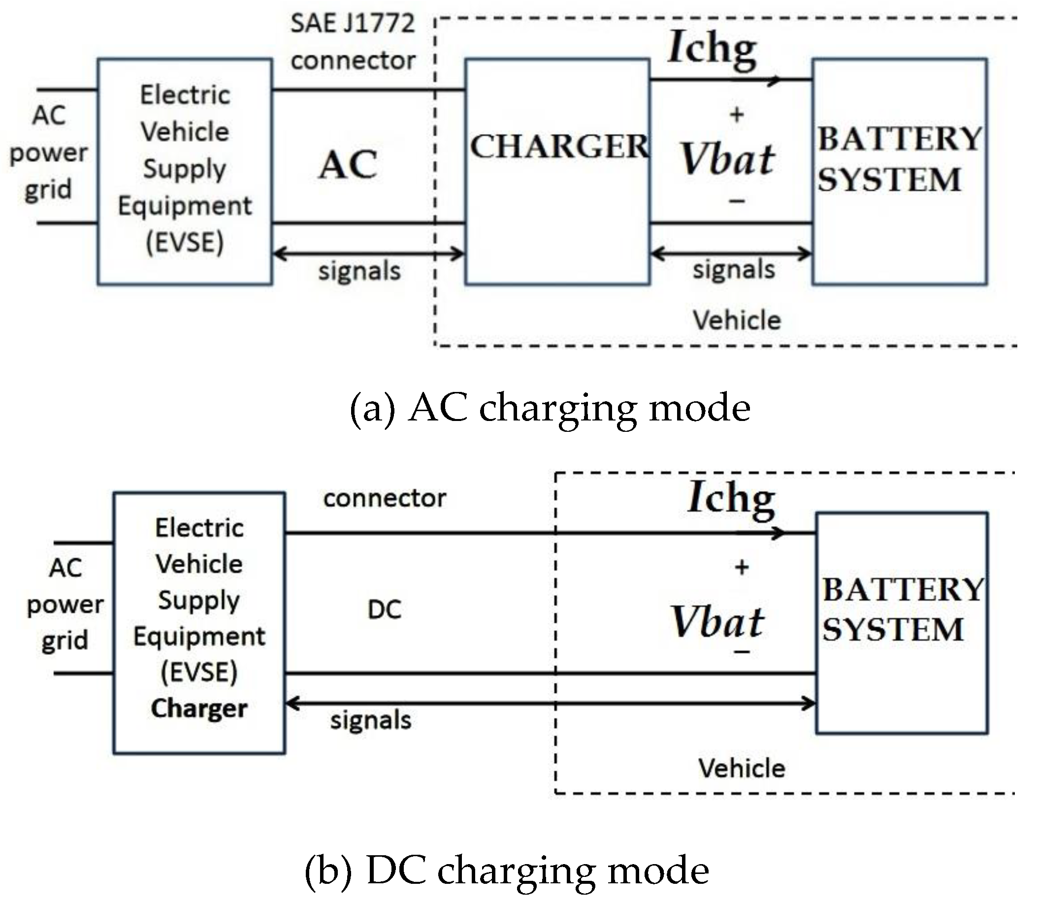
36]. The device that supplies the electricity from the grid to the electric vehicle is the EVSE and can provide alternating AC or DC direct current with different power values (
Figure 7). If EVSE supplies AC power, there is an AC power flow between the vehicle and the EVSE. Therefore, the vehicle has a built-in inverter to convert the AC to DC needed to charge the batteries. If EVSE provides DC power to the DC vehicle, then the DC reverse current flow is DC. In this case, the inverter is included in the off-board EVSE. The BMS (battery management system) assumes full charge control and battery discharge in V2G mode. More specifically, the BMS monitors the SOC (state of charge) of the battery or cells and adjusts the power level of the inverter.
During V2G operation, EVSE communicates with the network operator exchanging information on power demand. If the network requests power from the vehicle, it sends a request to EVSE. EVSE will then contact the BMS from which it will request validity. The BMS responds and controls the inverter to start the power flow. This happens when AC LEVEL is charged. For DC LEVEL charging, the current exchanged by the vehicle is DC. The inverter is mounted in the EVSE. In this case, the BMS controls the battery output. An important factor for battery longevity is the design of the BMS. If the charging and discharge is properly controlled, then the battery life is longer [
37].
6. Energy Management
There are four locations where vehicle owners will be able to charge their vehicles: in their own home, at their place of service, at the fleet’s fleet, or at commercial charging stations [
38].
6.1. Charging at Home
Here we have vehicle to home (V2H), which can be considered as a preliminary step for the V2G. Vehicle owners can use their cars as a source of energy for the household and save money on the electricity bill or provide backup power during power outages or backup power. Most home loads are achieved through AC level 2 charging due to lower charging times compared to AC LEVEL 1. There is also the option to charge DC LEVEL 1 with the appropriate EVSE. Note that if charging is done overnight, this available time is enough to restore battery power. As far as the AC LEVEL 3 load is concerned, it adds excessive load to the house’s electrical installation, and is not practical at all for single-family homes, because it requires upgrading the electrical installation, which is costly.
6.2. Charging at Work
Here we have the option of re-charging out of residence with the vehicle to building (V2B) script. An enterprise may have parking facilities for its customers, or staff, where recharging of EVs can take place. In this scenario, the company installs stations, from which many of them are combined with solar covers in order to achieve a better load management. Vehicles arriving at the workplace are immediately connected to fully recharge before the region’s demand is maximized. Charging can be at AC LEVEL 2 or AC LEVEL 3. The choice of the charge level depends on the nature of the space, and the requirements of the vehicles parked. With the vehicles connected to the stations, we have a significant amount of stored energy that can be used as a power supply for an office building in order to reduce costs or provide critical backup power for high availability business operations, such as data centers. Hοwever, a major drawback is that businesses have limited working hours. Thus, batteries may not be fully recharged sometimes, and the available vehicle power for home travel will not be enough.
6.3. Charging Fleet of Vehicles
Vehicle fleet charging has a common point with workload, as it appears in the working environment. The difference, however, is that CSs used here are for the cars belonging to the company. A business owner may own a significant number of EVs, and be connected to charging during the day and working hours that coincide with peak demand hours. But there is a possibility that these parked vehicles will be available for V2G services at the time the business does not work. Some types of EV fleets may have greater advantages in V2G technology than others. An example is a fleet of electric school buses. The buses have large capacity batteries and usually operate at specific times and days during the week, and then remain parked for known durations (one night and weekends). Therefore, a large amount of stored energy can be quickly disposed of during off-vehicle hours. As far as the loading levels are concerned, it is also the case in the workplace.
6.4. Commercial Charge
Here we are talking about CSs, which may be in public places such as motorways, airports, harbors, train stations, but also in businesses such as restaurants, theaters, entertainment centers, and doctors’ or lawyers’ offices for profit. Charge levels may vary. A station at a port or airport can be charged with AC LEVEL 2 or DC LEVEL 1, and the reason is that the vehicle users travel and leave the vehicles for a long time parked, without excluding the remaining levels of charge. However, at airports and ports we may have short-term parking areas with a need for fast charging. The charging requirements are AC LEVEL 3 and DC LEVEL 2. Other short-term spaces, such as fast food restaurants, cafes, department stores, and gas stations, also have the same charging requirements. CSs can be installed along motorways between large and remote cities. This enables a PEV to travel between areas where the distance is greater than the distance the vehicle can travel when fully charged.
6.5. Types of Charging Stations
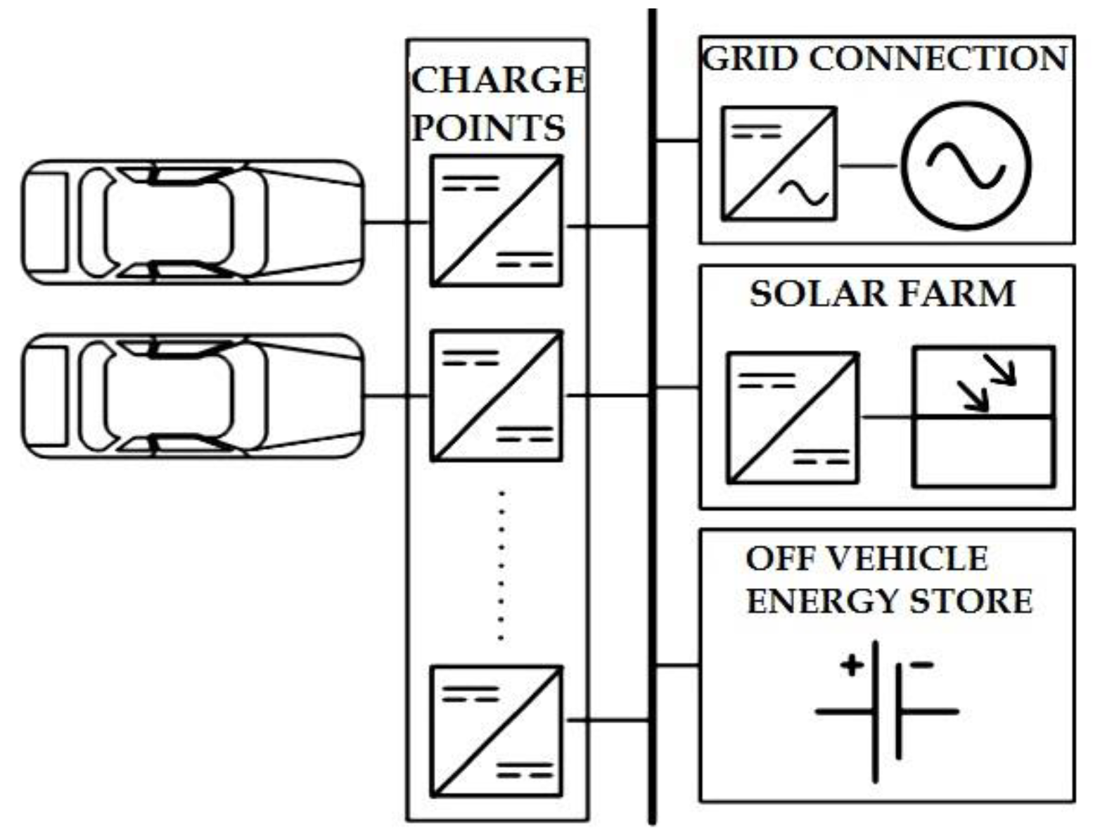
CS defines the charging infrastructure for the electric vehicle consisting of one or more charging points (CP) (
Figure 8) and their connection to the distribution network [
39,
40]. CSs can be categorized into two types: fixed charging station (FCS) and mobile charging station (MCS). FCS is a fixed installation with multiple charging points. Power is obtained directly from the main voltage through a transformer. Additional equipment that a station may include are generators, battery packs, or PV cells to ensure reliable EV charging. Given the ever-increasing number of EVs, it is essential to effectively plan the capacity and schedule the power supply for the EV charging stations. In [
41], a holistic framework has been developed for the planning and operation of an EV charging station, taking into consideration the supply of both the grid and local renewable energy. A review on system planning of grid-connected EV CSs and key technologies can be found in [
42]. Various charging methodologies are further analyzed in [
43].
The MCS is an electric or hybrid vehicle equipped with a small number of CPs and with some type of energy storage such as ultracapacitors. MCS units avoid some challenges associated with EV charging infrastructure. They avoid the need for designated EV parking spaces (and enforcement tools to prevent non-EV users from parking there), can disconnect as soon as charging is complete (allowing EV drivers to depart at will instead of on a set schedule), require less investment upfront investment (no trenching or permitting), and can be repositioned or sold if utilization is low [
44].
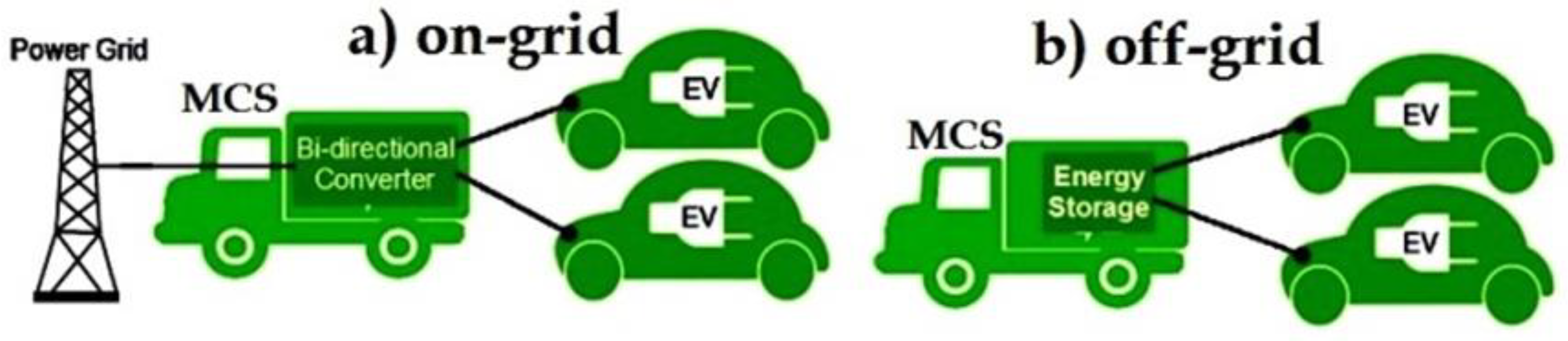
MCS’s main power source is the network. The MCS can park to a FCS with which it is connected and can charge the nearest EV. This charging function of the MCS is called “on-grid” because it charges the nearby EV using its connection to the power grid. MCS can also park to some FCS to charge energy storage. The advantage of MCS is to travel some distance, and park and charge an EV outside FCS using the stored energy. In this case, we have an off-grid charging function. Both modes are depicted in
Figure 9.
According to [
45], where the performance of FSC and MCS networks is analyzed, the MCS network has better waiting time performance than the FCS network. The advantage of the MCS network over the FCS network becomes very significant when the arrivals of EVs are large. Outage probability and service waiting delay performances of MCSs are also examined in [
46], where significant improvements are outlined. An alternate approach is proposed in [
47], where EVs can also act as mobile energy storage (MES) units. In this context, CSs inform the grid on their charging capabilities and EVs on their planned travel routes. In the case of a limited-capacity CS, the grid examines if a scheduled route is about to take place in due time, including the aforementioned CS and a resourceful CS. If this is true, then energy can be transferred via MESs. As was shown in [
47], the proposed scheme can be applied by the local power system operator (PSO) to balance the system energy without excessive power infrastructure upgrade, while MESs are stimulated to fulfill tasks in a cost-efficient way.
7. Autonomous Vehicles
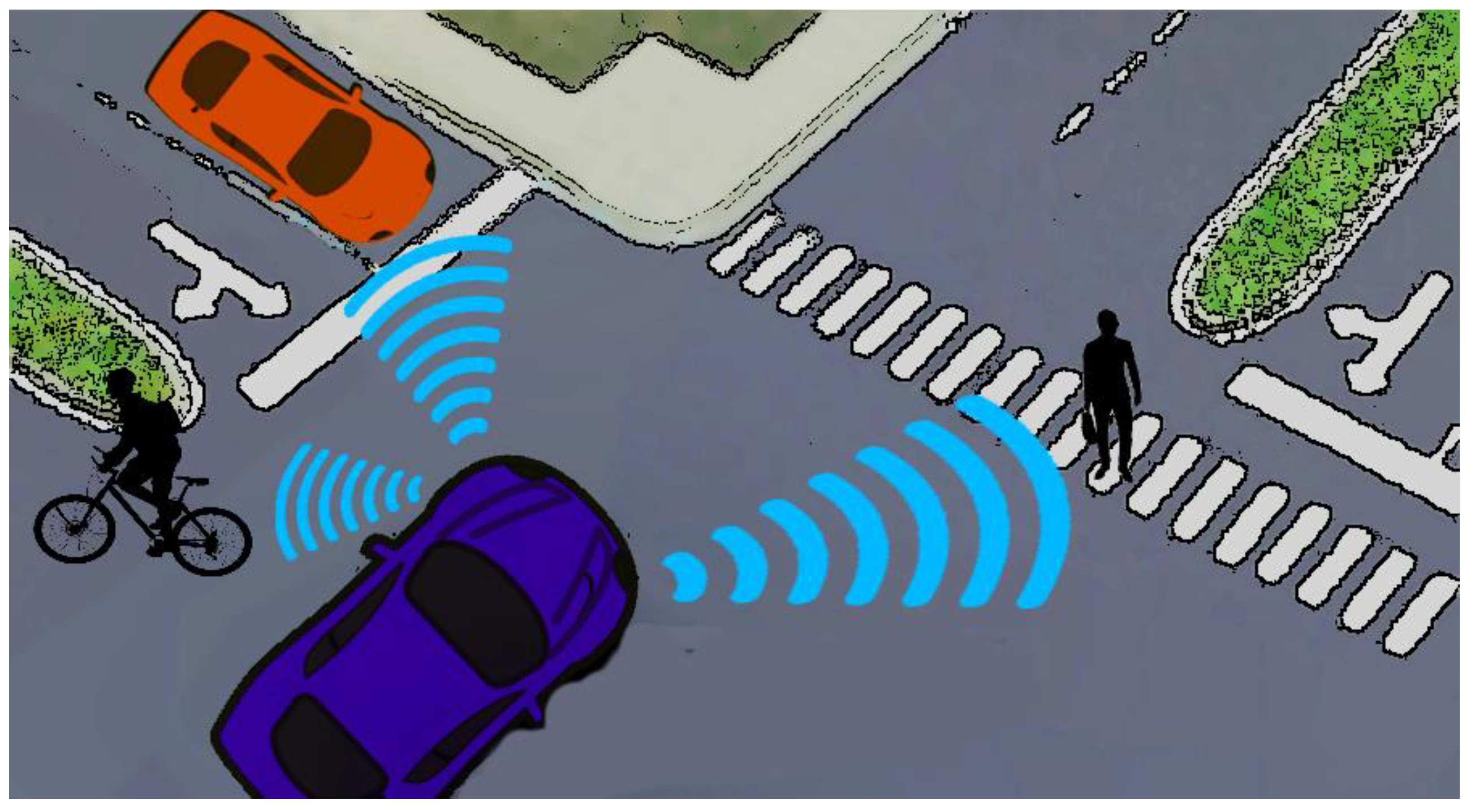
An autonomous vehicle (AV) is defined as any type of vehicle where all mechanical-related procedures (i.e., motion, acceleration, etc.) can be performed with limited or no human interaction (
Figure 10). In this context, two main classifications can be found in literature regarding AVs ([
48]): a. semi-autonomous, and b. fully autonomous. In the first case, semi-autonomous cars can accelerate, brake and steer, keep the distance from the car in front, and also keep the lane at speeds up to 130 km/h, but the driver is still required and is still in full control.
Nowadays, autonomous driving of smart vehicles has attracted scientific interest, as apart from wireless networks development, the concept of electric smart grids is shifting towards standardization and development. In addition to the advances in computing and perception hardware, this rapid progress has been enabled by major theoretical progress in the computational aspects of mobile robot motion planning and feedback control theory [
49,
50]. In this context, independent vehicles can perform various operations, such as delivery to individuals on demand, especially to elder people. Τherefore, the establishment of a reliable wireless link is of primary importance, as the vehicle needs to constantly receive information on road traffic and update scheduled tasks, receive on demand new orders, and finally be informed on power charging stations. By providing the vehicle with real time maps for navigation, speed warnings, road hazards, vulnerabilities, heads up display systems, sensor data sharing, etc., advanced driver assistance features will reduce fatal accidents and traffic congestion. These features will enable the vehicle to dynamically change its course on the road under certain scenarios and conditions. The so-called vehicle to network (V2N) communications are necessary for this use case, including short range modeling and recognition of surrounding objects and vehicles plus mid to long range modeling of the surroundings, with up-to-date information on the latest digital maps, traffic signs, traffic signal locations, road construction, and traffic congestion.
For autonomous driving technology to be unlocked, many experts agree that large-scale adoption of 5G—the next-generation wireless technology—is required [
51,
52], as 5G can run over existing infrastructure, though cellular stations upgrades are needed. Moreover, 5G could be one unifying connectivity standard technology that could avoid market and technical fragmentation and which could lower the cost for automotive manufacturers. According to scientific studies, 5G technology can also offer evolved prevention capabilities. In critical scenarios, such as car accidents, the detection and control system of an AV must have fast reaction times. Under this condition, a set of sensor technologies, for example, can achieve immediate communication with other autonomous cars, radar, lasers, sonar devices, and cameras [
53,
54,
55]. In current state, available LTE (4G) supports data transmission at 100 Mbps. On the other side, speed in 5G networks can reach up to 5Gbps. In that point of view, the deployment of 5G networks over the next decade is going to boost the development of AVs and increase corresponding safety.
8. Conclusions
The development of electrification with a view to exploiting renewable energy sources has begun. The final goal is the full interconnection of EVs to SEGs. This transition from one state to the other, i.e., the use of conventional vehicles at one end, and power-operated at the other, by exchanging electricity with the power grid, certainly cannot take place without intermediate steps. These steps mainly include HEVs, which can demonstrate the benefits of this new technology to consumers, and thus drive them smoothly to the prevalence of electric drive. The transition to electrification and V2G technology requires investment in this sector and additional costs, which can easily be compensated in the short or long term. In the first instance, the compensation is related to the direct economic benefits to the owner of the EV, and to the V2G network operator from the savings in the consumption of electricity. However, compensation is also related indirectly to the burden on the state budget to tackle the burden on the contamination of the environment by the use of non-renewable energy sources.
Moreover, technological developments in other related sectors (i.e., wireless communications as the era of 5G networks is approaching) can boost scientific advances in EV technology. AV concept offers beneficial energy usage and environmental advantages, and it may influence future world perspectives in various fields: traffic reduction, vehicle and driving safety, travel behavior, fuel efficiency, road crash prevention, and parking benefits.

 ,
, 


