Strategies for Enhancing the Low Wind Speed Performance of H-Darrieus Wind Turbine—Part 1

 , , ,
, , ,  and
and
Abstract
:1. Introduction
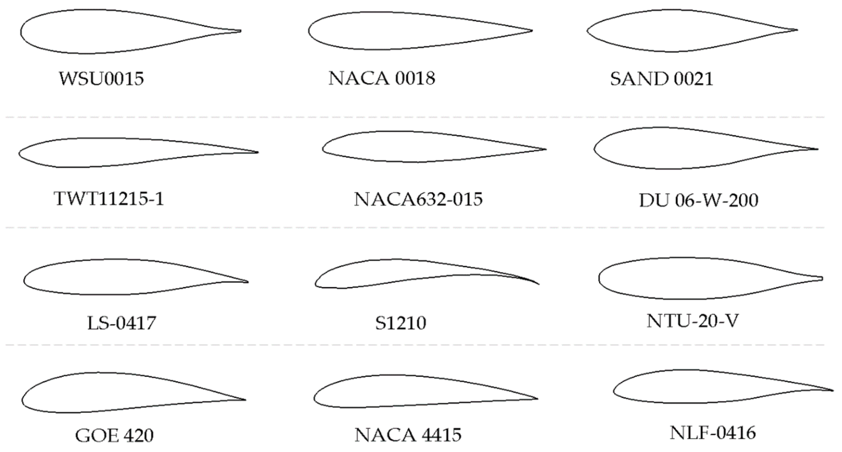
2. Airfoil Characteristics
- Operating wind speed range—Re range.
- Fixed pitch or pitch able blades.
- Straight blades or helical blades.
- Installation environment-urban or rural location.
- Self-start or assisted start such as motor start
- Drive train arrangement—Resistive torque and efficiency.
- The manufacturing method of blades-Aluminum extrusion or moulding.
2.1. WSU 0015
2.2. NACA00XX
2.3. SAND00XX/XX
2.4. TWT 11215-1
2.5. NACA 6 Series
2.6. ARC Series
2.7. DU 06-W-200
2.8. LS-0417
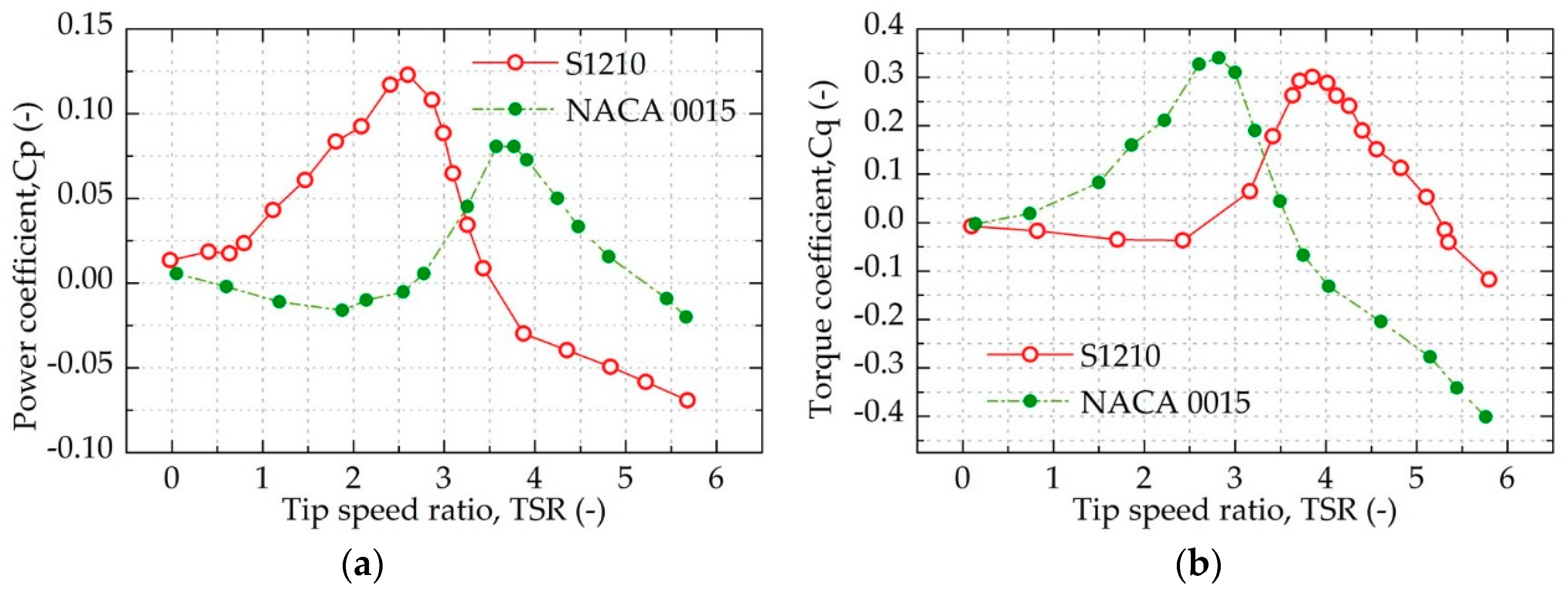
2.9. S1210
2.10. NTU-20-V
3. Camber and Symmetric Airfoils
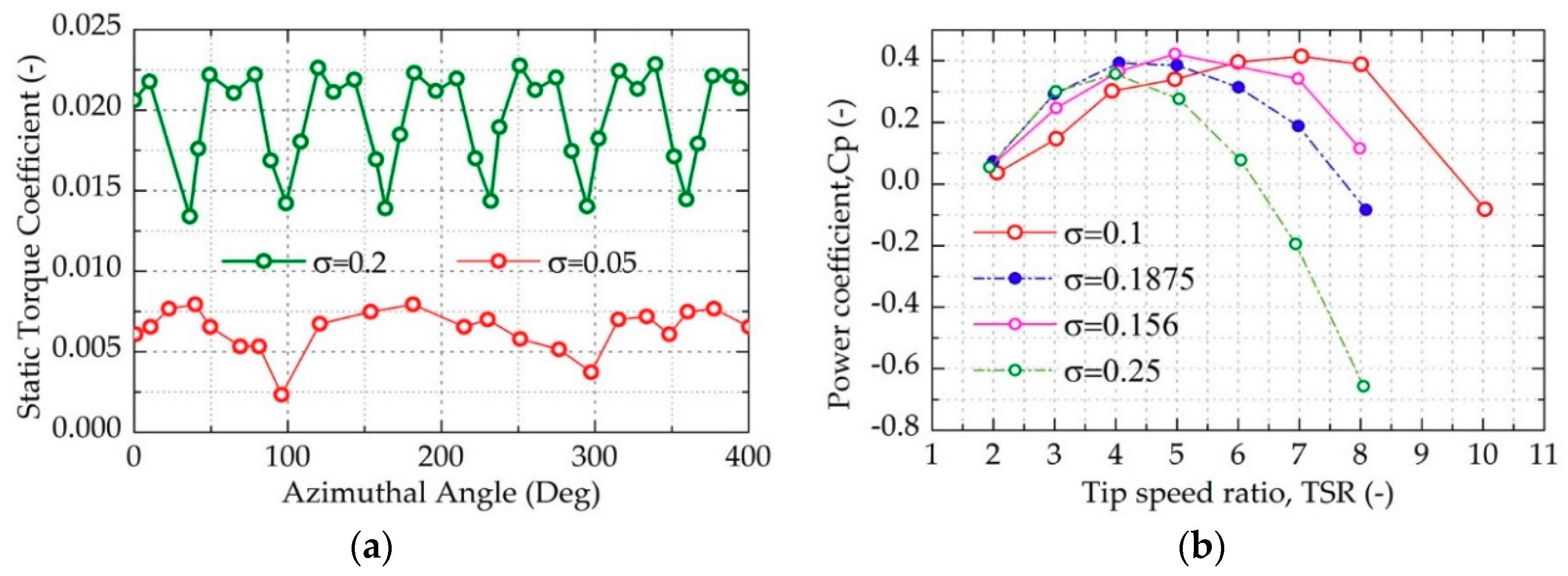
4. Solidity
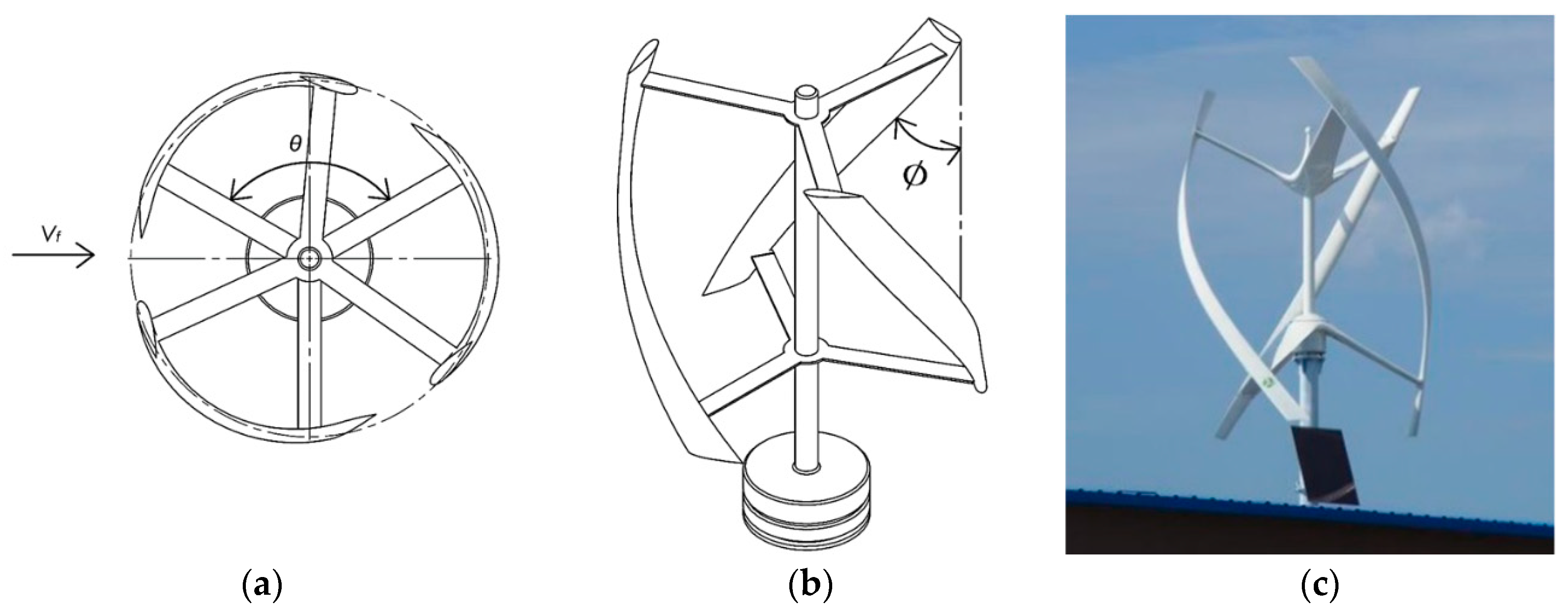
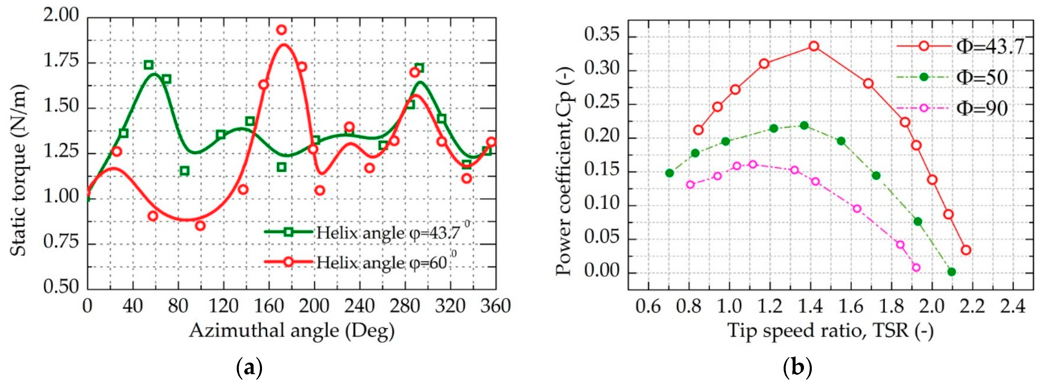
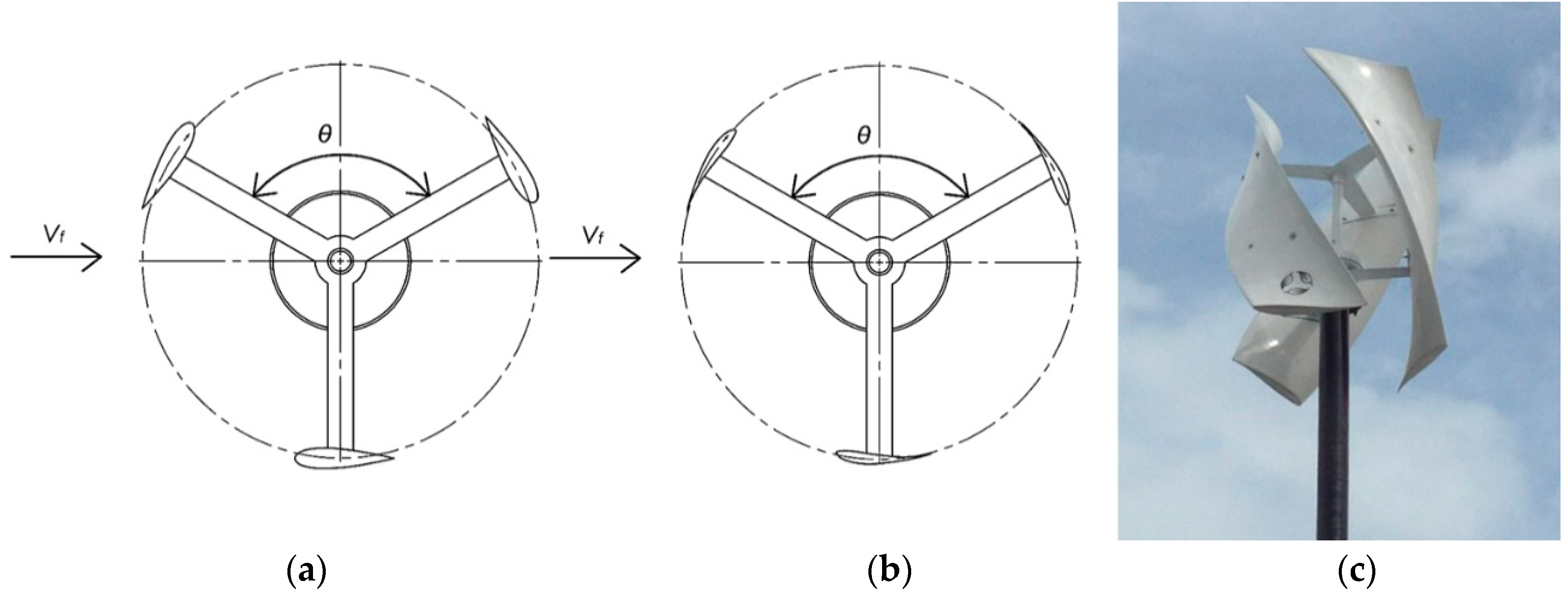
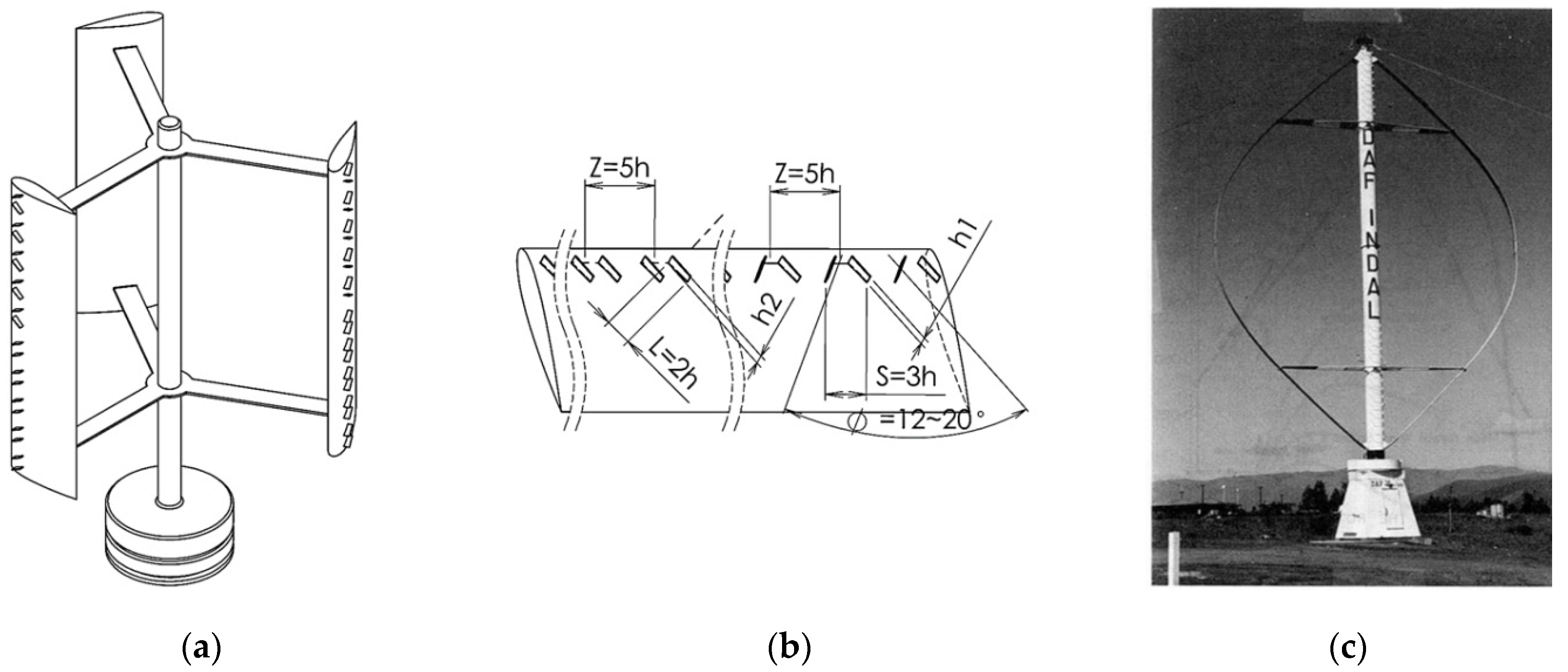
5. Helical Blades
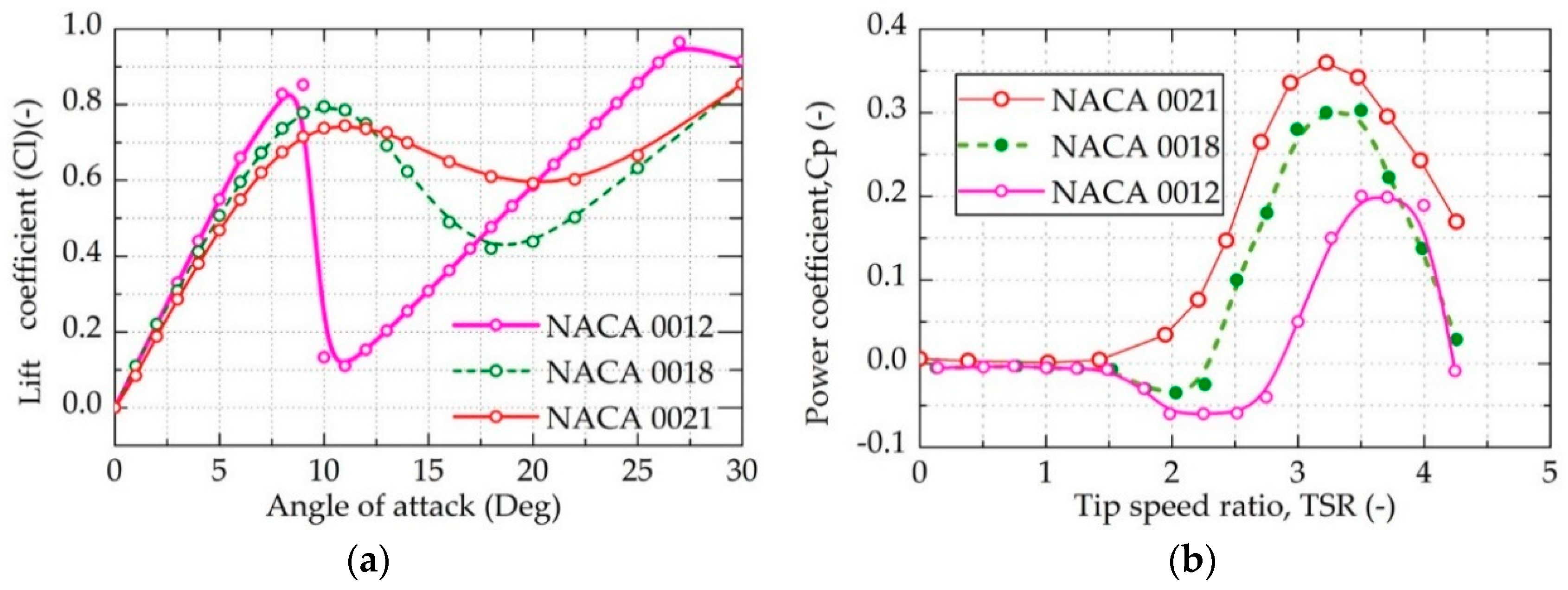
6. Blade Thickness
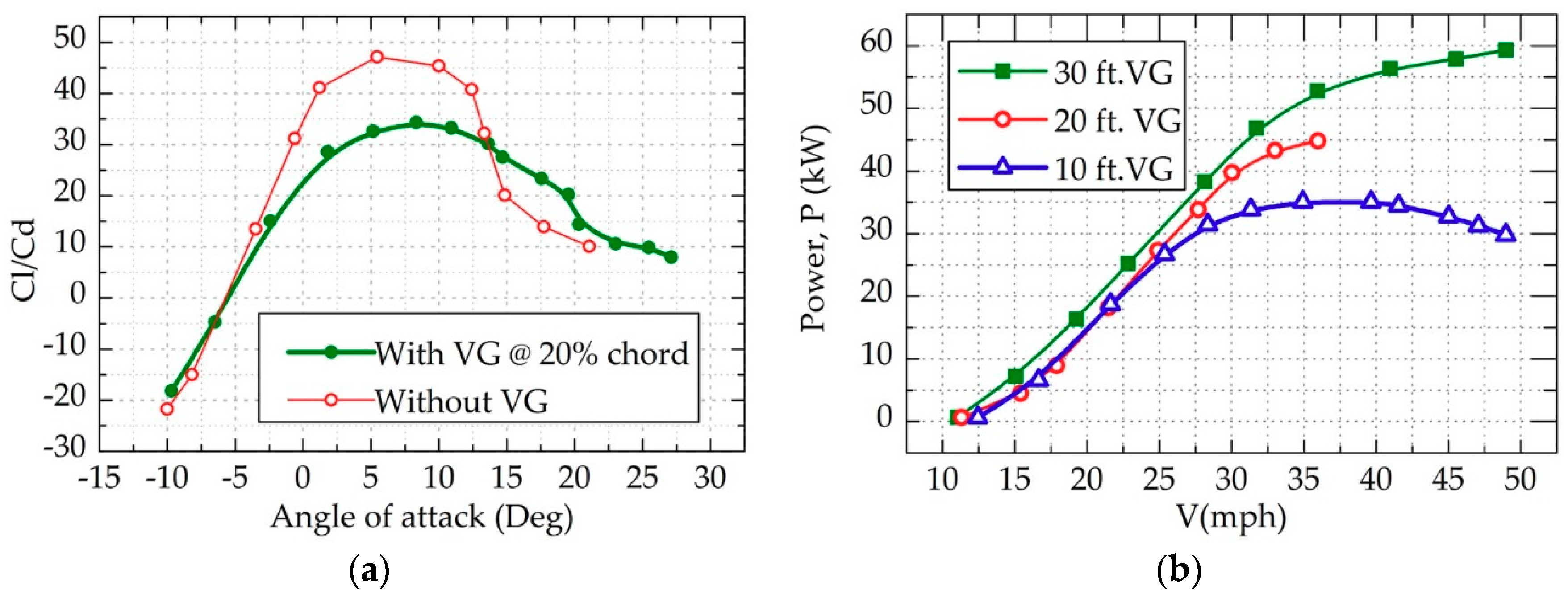
7. Vortex Generators
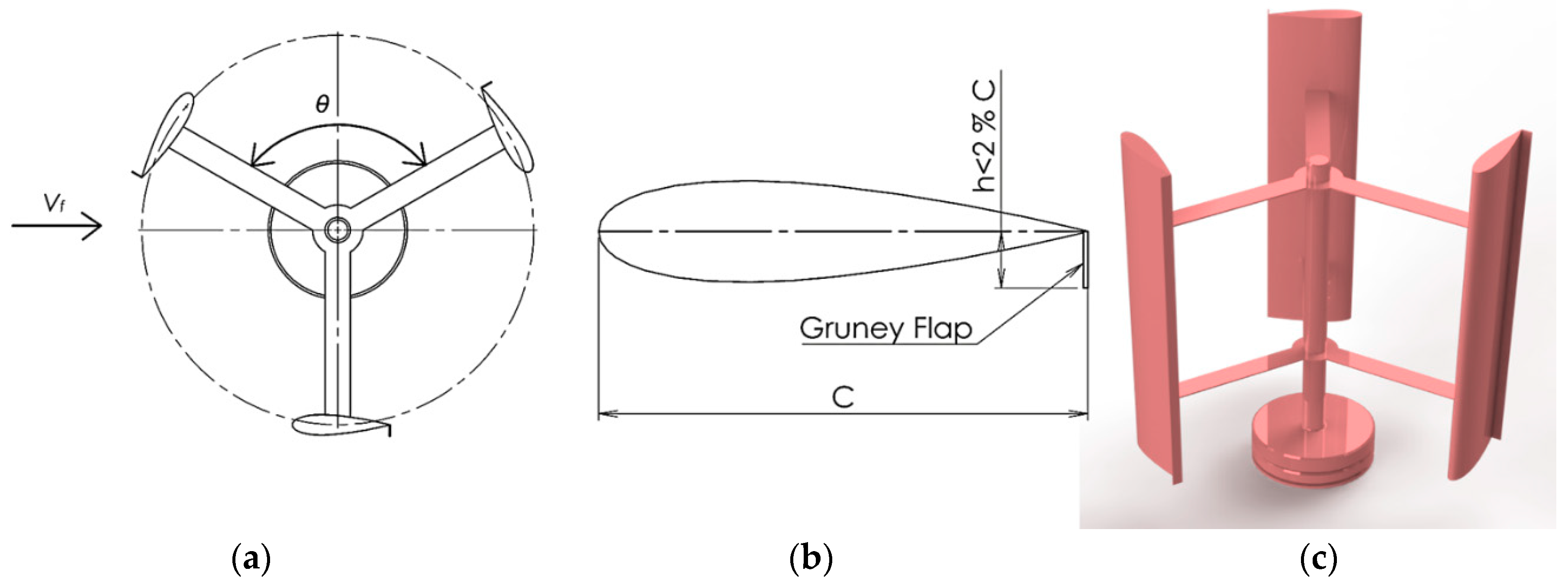
8. Gurney Flaps
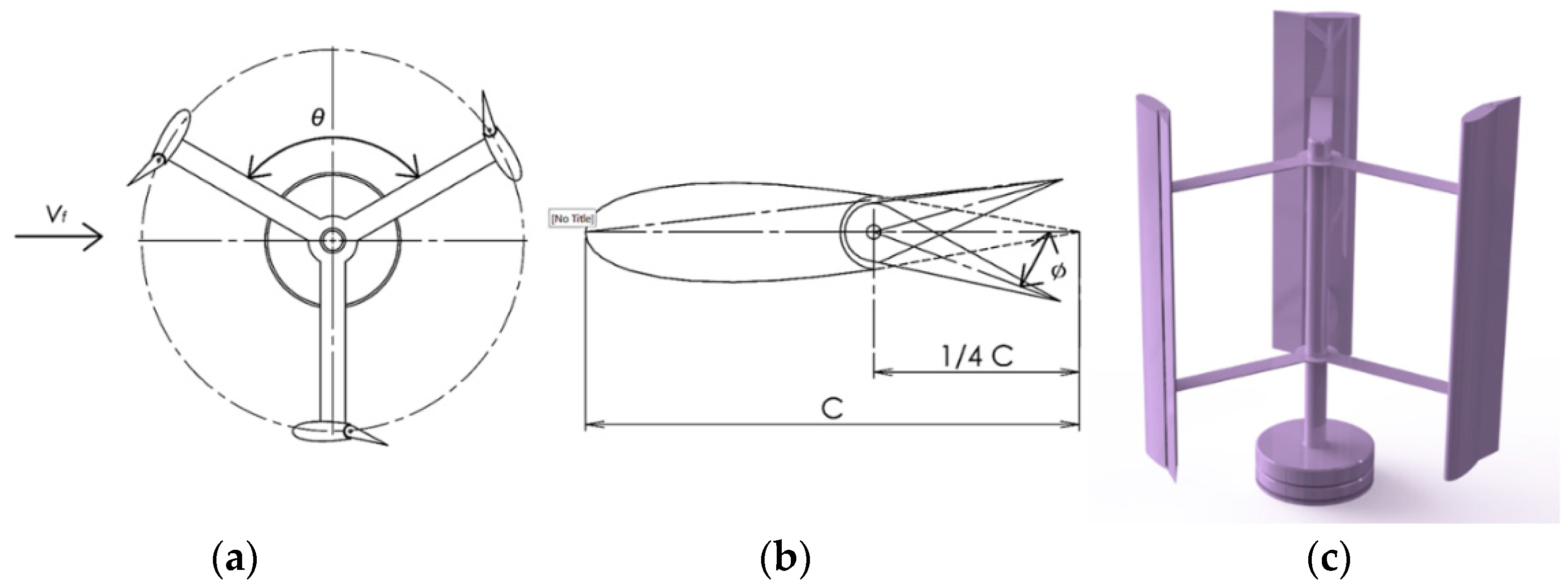
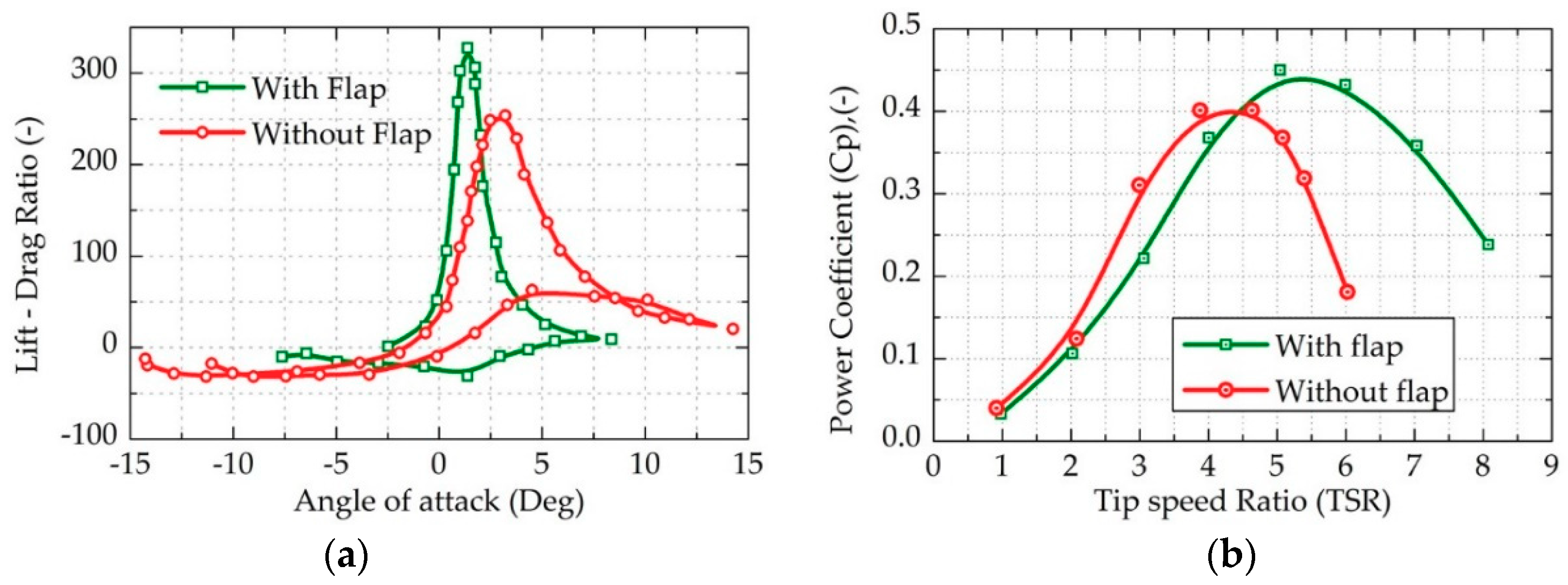
9. Trailing Edge Flaps
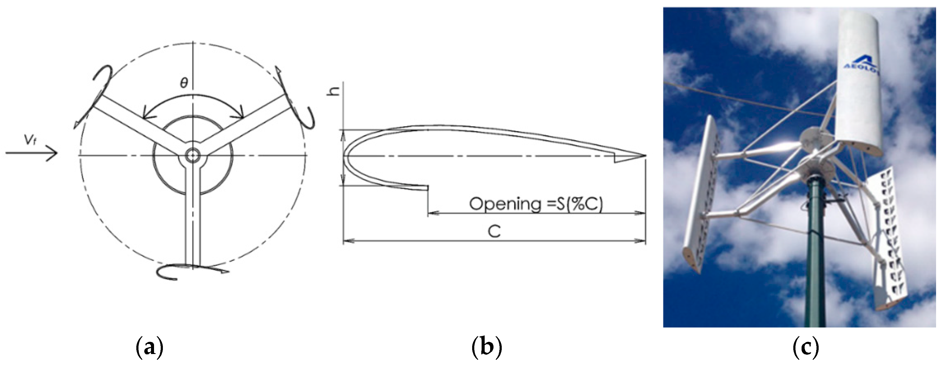
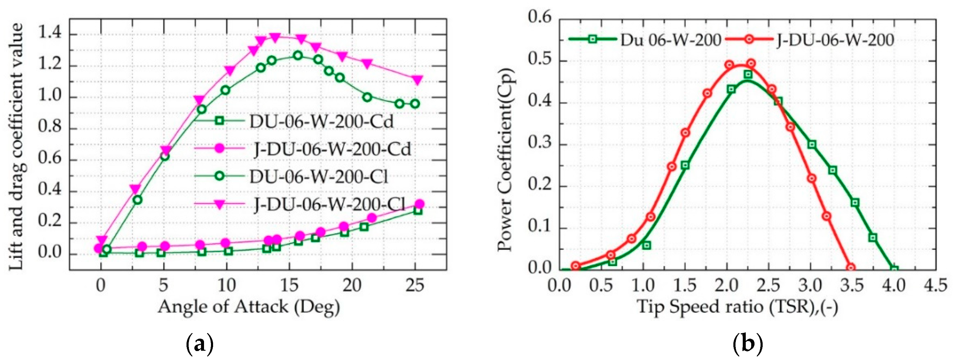
10. J-Blade
11. Conclusions
Author Contributions
Funding
Conflicts of Interest
References
- Li, Y.; Wu, X.-P.; Li, Q.-S.; Tee, K.F. Assessment of onshore wind energy potential under different geographical climate conditions in China. Energy 2018, 152, 498–511. [Google Scholar] [CrossRef]
- Noyes, C.; Qin, C.; Loth, E. Pre-aligned downwind rotor for a 13.2 MW wind turbine. Renew. Energy 2018, 116, 749–754. [Google Scholar] [CrossRef]
- Korprasertsak, N.; Leephakpreeda, T. Analysis and optimal design of wind boosters for Vertical Axis Wind Turbines at low wind speed. J. Wind Eng. Ind. Aerodyn. 2016, 159, 9–18. [Google Scholar] [CrossRef]
- Mohan Kumar, P.; Surya, M.M.R.; Narasimalu, S.; Lim, T.-C. Experimental and numerical investigation of novel Savonius wind turbine. Wind Eng. 2018, 43, 247–262. [Google Scholar] [CrossRef]
- Kumar, P.M.; Purimitla, S.R.; Shubhra, S.; Srikanth, N. Numerical and analytical study on telescopic savonius turbine blade. In Proceedings of the 2017 3rd International Conference on Power Generation Systems and Renewable Energy Technologies (PGSRET), Johor Bahru, Malaysia, 4–6 April 2017; pp. 107–112. [Google Scholar]
- Joo, S.; Choi, H.; Lee, J. Aerodynamic characteristics of two-bladed H-Darrieus at various solidities and rotating speeds. Energy 2015, 90, 439–451. [Google Scholar] [CrossRef]
- Kumar, P.M.; Sivalingam, K.; Narasimalu, S.; Lim, T.C.; Ramakrishna, S.; Wei, H. A Review on the Evolution of Darrieus Vertical Axis Wind Turbine: Small Wind Turbines. J. Power Energy Eng. 2019, 7, 27–44. [Google Scholar] [CrossRef] [Green Version]
- Islam, M.; Ting, D.S.; Fartaj, A. Desirable airfoil features for smaller-capacity straight-bladed VAWT. Wind Eng. 2007, 31, 165–196. [Google Scholar] [CrossRef]
- Laneville, A.; Vittecoq, P. Dynamic stall: The case of the vertical axis wind turbine. J. Sol. Energy Eng. 1986, 108, 140–145. [Google Scholar] [CrossRef]
- Timmer, W.; Van Rooij, R. Summary of the Delft University wind turbine dedicated airfoils. ASME-J. Sol. Energy Eng. 2003, 125, 488–496. [Google Scholar] [CrossRef]
- Jasinski, W.J.; Noe, S.C.; Selig, M.S.; Bragg, M.B. Wind turbine performance under icing conditions. Trans.-ASME-J. Sol. Energy Eng. 1998, 120, 60–65. [Google Scholar] [CrossRef]
- Shepherd, D.; McBride, D.; Welch, D.; Dirks, K.N.; Hill, E.M. Evaluating the impact of wind turbine noise on health-related quality of life. Noise Health 2011, 13, 333. [Google Scholar] [CrossRef] [PubMed]
- Kato, Y.; Seki, K. Vertical axis wind turbine designed aerodynamically at Tokai University. Period. Polytech. Mech. Engi. 1981, 25, 47–56. [Google Scholar]
- Snyder, M.H.; Furukawa, N. WER-6: Comparison of Performance of Darrieus Wind Turbines Having 12% and 21% Thick Sections; Center for Energy Studies, Wichita State University: Wichita, Kansas, 1979. [Google Scholar]
- Sheldahl, R.E.; Klimas, P.C. Aerodynamic Characteristics of Seven Symmetrical Airfoil Sections through 180-Degree Angle of Attack for Use in Aerodynamic Analysis of Vertical Axis Wind Turbines; Sandia National Labs.: Albuquerque, NM, USA, 1981. [Google Scholar]
- Sutherland, H.J.; Berg, D.E.; Ashwill, T.D. A Retrospective of VAWT Technology; Sandia Report No. SAND2012-0304; Sandia National Laboratories: Albuquerque, NM, USA, 2012. [Google Scholar]
- Kumar, P.M.; Rashmitha, S.R.; Srikanth, N.; Lim, T.-C. Wind Tunnel Validation of Double Multiple Streamtube Model for Vertical Axis Wind Turbine. Smart Grid Renew. Energy 2017, 8, 412. [Google Scholar] [CrossRef]
- Migliore, P. Comparison of NACA 6-series and 4-digit airfoils for Darrieus wind turbines. J. Energy 1983, 7, 291–292. [Google Scholar] [CrossRef]
- Zervos, A. Aerodynamic evaluation of blade profiles for vertical axis wind turbines. In Proceedings of the European Community Wind Energy Conference, Herning, Denmark, 6–10 June 1988; pp. 611–616. [Google Scholar]
- Claessens, M. The Design and Testing of Airfoils for Application in Small Vertical Axis Wind Turbines. Master’s Thesis, Delft University of Technology, Delft, The Netherlands, 2006. [Google Scholar]
- McGhee, R.J.; Beasley, W.D. Wind-Tunnel Results for a Modified 17-Percent-Thick Low-Speed Airfoil Section; NASA Langley Research Center: Hampton, VA, USA, 1981.
- Singh, M.; Biswas, A.; Misra, R. Investigation of self-starting and high rotor solidity on the performance of a three S1210 blade H-type Darrieus rotor. Renew. Energy 2015, 76, 381–387. [Google Scholar] [CrossRef]
- Kumar, M.; Surya, M.M.R.; Sin, N.P.; Srikanth, N. Design and experimental investigation of airfoil for extruded blades. Int. J. Adv. Agric. Environ. Eng. (IJAAEE) 2017, 3, 2349–2523. [Google Scholar]
- Kumar, P.M.; Surya, M.M.R.; Srikanth, N. On the improvement of starting torque of darrieus wind turbine with trapped vortex airfoil. In Proceedings of the 2017 IEEE International Conference on Smart Grid and Smart Cities (ICSGSC), Singapore, 23–26 July 2017; pp. 120–125. [Google Scholar]
- Kumar, P.M.; Surya, M.M.R.; Kethala, R.; Srikanth, N. Experimental investigation of the performance of darrieus wind turbine with trapped vortex airfoil. In Proceedings of the 2017 3rd International Conference on Power Generation Systems and Renewable Energy Technologies (PGSRET), Johor Bahru, Malaysia, 4–6 April 2017; pp. 130–135. [Google Scholar]
- Kumar, P.M.; Kulkarni, R.; Srikanth, N.; Lim, T.-C. Performance Assessment of Darrieus Turbine with Modified Trailing Edge Airfoil for Low Wind Speeds. Smart Grid Renew. Energy 2017, 8, 425. [Google Scholar] [CrossRef]
- Kumar, P.M.; Surya, M.M.R.; Srikanth, N. Comparitive CFD analysis of darrieus wind turbine with NTU-20-V and NACA0018 airfoils. In Proceedings of the 2017 IEEE International Conference on Smart Grid and Smart Cities (ICSGSC), Singapore, 23–26 July 2017; pp. 108–114. [Google Scholar]
- Rainbird, J.M.; Bianchini, A.; Balduzzi, F.; Peiró, J.; Graham, J.M.R.; Ferrara, G.; Ferrari, L. On the influence of virtual camber effect on airfoil polars for use in simulations of Darrieus wind turbines. Energy Convers. Manag. 2015, 106, 373–384. [Google Scholar] [CrossRef]
- Islam, M.; Ting, D.S.; Fartaj, A. Design of a special-purpose airfoil for smaller-capacity straight-bladed VAWT. Wind Eng. 2007, 31, 401–424. [Google Scholar] [CrossRef]
- Kirke, B.K. Evaluation of Self-Starting Vertical Axis Wind Turbines for Stand-Alone Applications; Griffith University Australia: Queensland, Australia, 1998. [Google Scholar]
- Healy, J. The influence of blade camber on the output of vertical-axis wind turbines. Wind Eng. 1978, 2, 146–155. [Google Scholar]
- Ågren, O.; Berg, M.; Leijon, M. A time-dependent potential flow theory for the aerodynamics of vertical axis wind turbines. J. Appl. Phys. 2005, 97, 104913. [Google Scholar] [CrossRef]
- Mohamed, M. Impacts of solidity and hybrid system in small wind turbines performance. Energy 2013, 57, 495–504. [Google Scholar] [CrossRef]
- El-Samanoudy, M.; Ghorab, A.; Youssef, S.Z. Effect of some design parameters on the performance of a Giromill vertical axis wind turbine. Ain Shams Eng. J. 2010, 1, 85–95. [Google Scholar] [CrossRef] [Green Version]
- Worasinchai, S.; Ingram, G.L.; Dominy, R.G. The Physics of H-Darrieus Turbine Starting Behavior. J. Eng. Gas Turbines Power 2015, 138, 062605. [Google Scholar] [CrossRef] [Green Version]
- Staelens, Y.; Saeed, F.; Paraschivoiu, I. A Straight-Bladed Variable-Pitch VAWT Concept for Improved Power Generation. AIAA Pap. 2003, 146–154. [Google Scholar] [CrossRef]
- Mohamed, M. Aero-acoustics noise evaluation of H-rotor Darrieus wind turbines. Energy 2014, 65, 596–604. [Google Scholar] [CrossRef]
- Gorlov, A. Development of the Helical Reaction Hydraulic Turbine. Final Technical Report, 1 July 1996–30 June 1998; Northeastern University: Boston, MA, USA, 1998. [Google Scholar]
- Baker, J. Features to aid or enable self starting of fixed pitch low solidity vertical axis wind turbines. J. Wind Eng. Ind. Aerodyn. 1983, 15, 369–380. [Google Scholar] [CrossRef]
- Purser, P.E.; Spearman, M.L. Wind-Tunnel Tests at Low Speed of Swept and Yawed Wings Having Various Plan Forms; NASA: Washington, DC, USA, 1951.
- Shiono, M.; Suzuki, K.; Kiho, S. Output characteristics of Darrieus water turbine with helical blades for tidal current generations. In Proceedings of the Twelfth International Offshore and Polar Engineering Conference, Kitakyushu, Japan, 26–31 May 2002. [Google Scholar]
- Blackwell, B.; Reis, G. Blade Shape for a Troposkien Type of Vertical-Axis Wind Turbine; Sandia Labs.: Albuquerque, NM, USA, 1974. [Google Scholar]
- Danao, L.A.; Qin, N.; Howell, R. A numerical study of blade thickness and camber effects on vertical axis wind turbines. Proc. Inst. Mech. Eng. Part A J. Power Energy 2012, 226, 867–881. [Google Scholar] [CrossRef]
- Batista, N.; Melício, R.; Marias, J.; Catalão, J. Self-start evaluation in lift-type vertical axis wind turbines: Methodology and computational tool applied to asymmetrical airfoils. In Proceedings of the Power Engineering, Energy and Electrical Drives (POWERENG), 2011 International Conference, Malaga, Spain, 11–13 May 2011; pp. 1–6. [Google Scholar]
- Alam, M.; Iqbal, M. A low cut-in speed marine current turbine. J. Ocean Technol. 2010, 5, 49–61. [Google Scholar]
- Parchen, R.; Bruggeman, J.; Dassen, A. The effect of the blade thickness of wind turbine blades on the noise due to inflow turbulence. Acustica 1996, 82, S82. [Google Scholar]
- Mueller-Vahl, H.; Pechlivanoglou, G.; Nayeri, C.; Paschereit, C. Vortex Generators for Wind Turbine Blades: A Combined Wind Tunnel and Wind Turbine Parametric Study; ASME Paper No. GT2012-69197; American Society of Mechanical Engineers: New York, NY, USA, 2012. [Google Scholar]
- Quinlan, P.; Scheffler, R.; Wehrey, M. Performance Test Results of Vortex Generators Attached to a Vertical Axis Wind Turbine. In Proceedings of the 7th ASME Wind Energy Symposium, New Orleans, LA, USA, 10–13 January 1988; p. 16. [Google Scholar]
- Seshagiri, A.; Cooper, E.; Traub, L.W. Effects of vortex generators on an airfoil at low Reynolds numbers. J. Aircr. 2009, 46, 116. [Google Scholar] [CrossRef]
- Paraschivoiu, I. Wind Turbine Design: With Emphasis on Darrieus Concept; International Polytechnic Press: Quebec, Canada, 2002. [Google Scholar]
- Zerihan, J.; Zhang, X. Aerodynamics of Gurney flaps on a wing in ground effect. AIAA J. 2001, 39, 772–780. [Google Scholar] [CrossRef]
- Zayas, J.; Van Dam, C.; Chow, R.; Baker, J.; Mayda, E. Active aerodynamic load control for wind turbine blades. In Proceedings of the European Wind Energy Conference, Athens, Greece, 27 February–2 March 2006. [Google Scholar]
- Liu, T.; Montefort, J. Thin-airfoil theoretical interpretation for Gurney flap lift enhancement. J. Aircr. 2007, 44, 667–671. [Google Scholar] [CrossRef]
- Liebeck, R.H. Design of subsonic airfoils for high lift. J. Aircr. 1978, 15, 547–561. [Google Scholar] [CrossRef]
- Xu, Z.; Wang, Q.; Dai, G.; Tan, H.; Zhong, Y. Study on improvement in aerodynamic performance of Vertical Axis Wind Turbine using Gurney flap. In Proceedings of the 2011 Second International Conference on Mechanic Automation and Control Engineering, Hohhot, China, 15–17 July 2011; pp. 6884–6887. [Google Scholar] [CrossRef]
- Viswamurthy, S.R.; Ganguli, R. An optimization approach to vibration reduction in helicopter rotors with multiple active trailing edge flaps. Aerosp. Sci. Technol. 2004, 8, 185–194. [Google Scholar] [CrossRef]
- Joncas, S.; Bergsma, O.; Beukers, A. Power regulation and optimization of offshore wind turbines through trailing edge flap control. In Proceedings of the 43th AIAA Aerospace Science Meeting and Exhibit, Reno, NV, USA, 10–13 January 2005; pp. 10–13. [Google Scholar]
- Castaignet, D.; Barlas, T.; Buhl, T.; Poulsen, N.K.; Wedel-Heinen, J.J.; Olesen, N.A.; Bak, C.; Kim, T. Full-scale test of trailing edge flaps on a Vestas V27 wind turbine: Active load reduction and system identification. Wind Energy 2014, 17, 549–564. [Google Scholar] [CrossRef]
- Yang, Y.; Li, C.; Zhang, W.; Guo, X.; Yuan, Q. Investigation on aerodynamics and active flow control of a vertical axis wind turbine with flapped airfoil. J. Mech. Sci. Technol. 2017, 31, 1645–1655. [Google Scholar] [CrossRef]
- Zamani, M.; Maghrebi, M.J.; Varedi, S.R. Starting torque improvement using J-shaped straight-bladed Darrieus vertical axis wind turbine by means of numerical simulation. Renew. Energy 2016, 95, 109–126. [Google Scholar] [CrossRef]
- Zamani, M.; Nazari, S.; Moshizi, S.A.; Maghrebi, M.J. Three dimensional simulation of J-shaped Darrieus vertical axis wind turbine. Energy 2016, 116, 1243–1255. [Google Scholar] [CrossRef]
- Chen, J.; Yang, H.; Yang, M.; Xu, H. The effect of the opening ratio and location on the performance of a novel vertical axis Darrieus turbine. Energy 2015, 89, 819–834. [Google Scholar] [CrossRef]


| Strategy | Merits | Demerits |
|---|---|---|
| Airfoil characteristics | Less complex, cost-effective, better optimization of dynamic stall, blade tip loss. Increased structural rigidity | Minimal improvement in starting performance and overall power coefficient |
| Cambered airfoil | Better starting capability delayed stall, less sensitive to surface roughness, high pitching moment | Increased drag on the down half, reduction in power coefficient |
| Solidity | Increased starting torque, low centrifugal forces due to low rpm | Large AoA, large drive train size and additional cost due to an increased number of blades |
| Helical blades | Improved aesthetics, smooth torque pulsation leading to reduced vibration | High manufacturing cost of blades, low torque for every azimuthal position |
| Blade thickness | Better performance at low Re delayed stall and structurally sound | Increased profile drag at high Re and noise |
| Vortex generators | Improved performance at low Re, extended dynamic stall and marginal improvement in starting torque | Increased drag at high TSR and increases noise due to vortex shedding |
| Gurney flaps | Delayed dynamic stall with an increase in starting torque compared to a conventional airfoil | Vibration after stall and noise due to vortex shedding |
| Trailing edge flaps | Better performance in high and low TSR, able to regulate the rotor rpm aerodynamically | Power has to be expended to operate flaps, requires a sophisticated control system |
| J-Blade | Excellent startup torque, able to sustain low wind speed rotation, ease of blade manufacturing | Degraded performance at high TSR due to high form drag at high Re and increased fatigue failure of blades |
© 2019 by the authors. Licensee MDPI, Basel, Switzerland. This article is an open access article distributed under the terms and conditions of the Creative Commons Attribution (CC BY) license (http://creativecommons.org/licenses/by/4.0/).
Share and Cite
Mohan Kumar, P.; Sivalingam, K.; Lim, T.-C.; Ramakrishna, S.; Wei, H. Strategies for Enhancing the Low Wind Speed Performance of H-Darrieus Wind Turbine—Part 1. Clean Technol. 2019, 1, 185-204. https://doi.org/10.3390/cleantechnol1010013
Mohan Kumar P, Sivalingam K, Lim T-C, Ramakrishna S, Wei H. Strategies for Enhancing the Low Wind Speed Performance of H-Darrieus Wind Turbine—Part 1. Clean Technologies. 2019; 1(1):185-204. https://doi.org/10.3390/cleantechnol1010013
Chicago/Turabian StyleMohan Kumar, Palanisamy, Krishnamoorthi Sivalingam, Teik-Cheng Lim, Seeram Ramakrishna, and He Wei. 2019. "Strategies for Enhancing the Low Wind Speed Performance of H-Darrieus Wind Turbine—Part 1" Clean Technologies 1, no. 1: 185-204. https://doi.org/10.3390/cleantechnol1010013