
Thermal Characteristics of Epoxy Fire-Retardant Coatings under Different Fire Regimes


Abstract
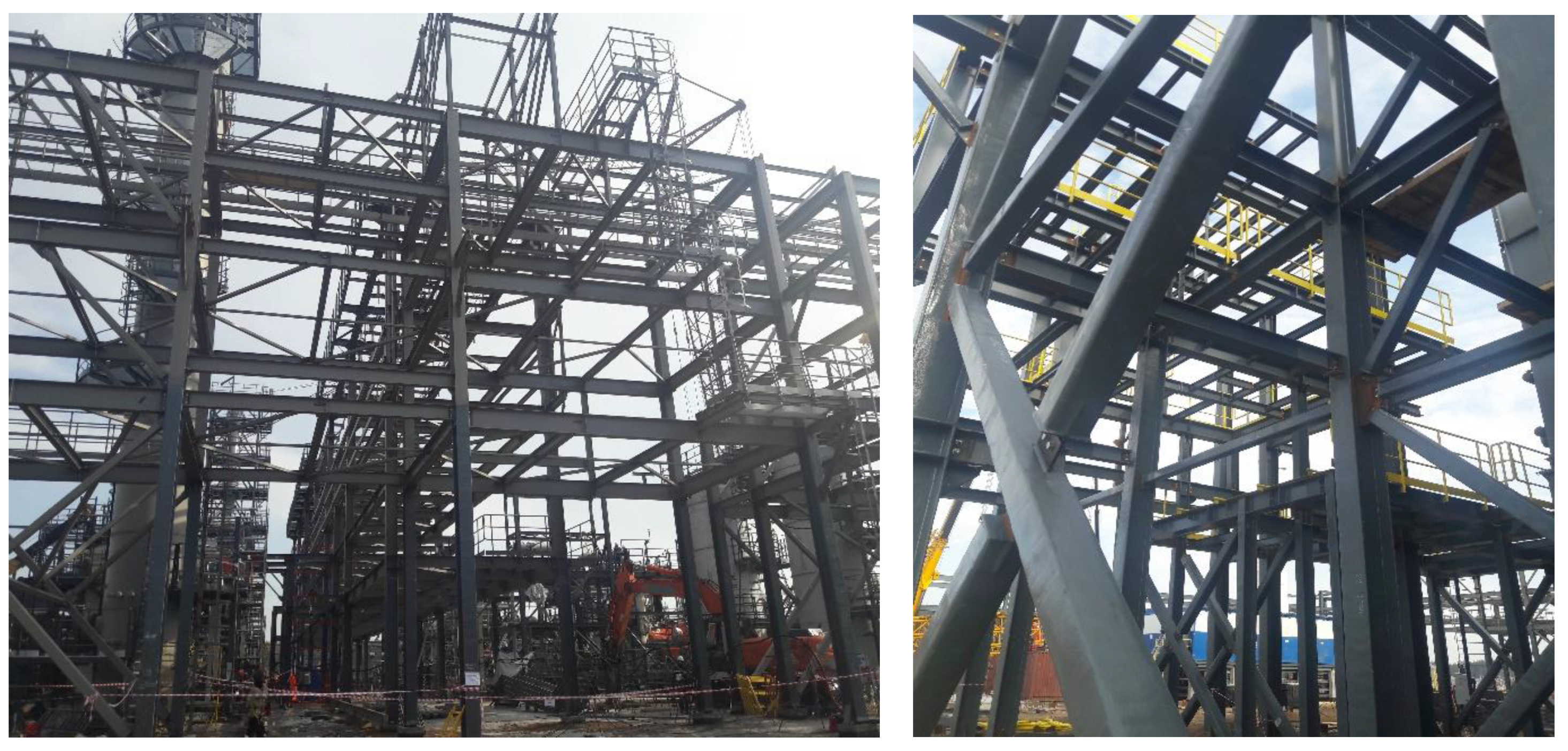
:1. Introduction
2. Materials and Methods
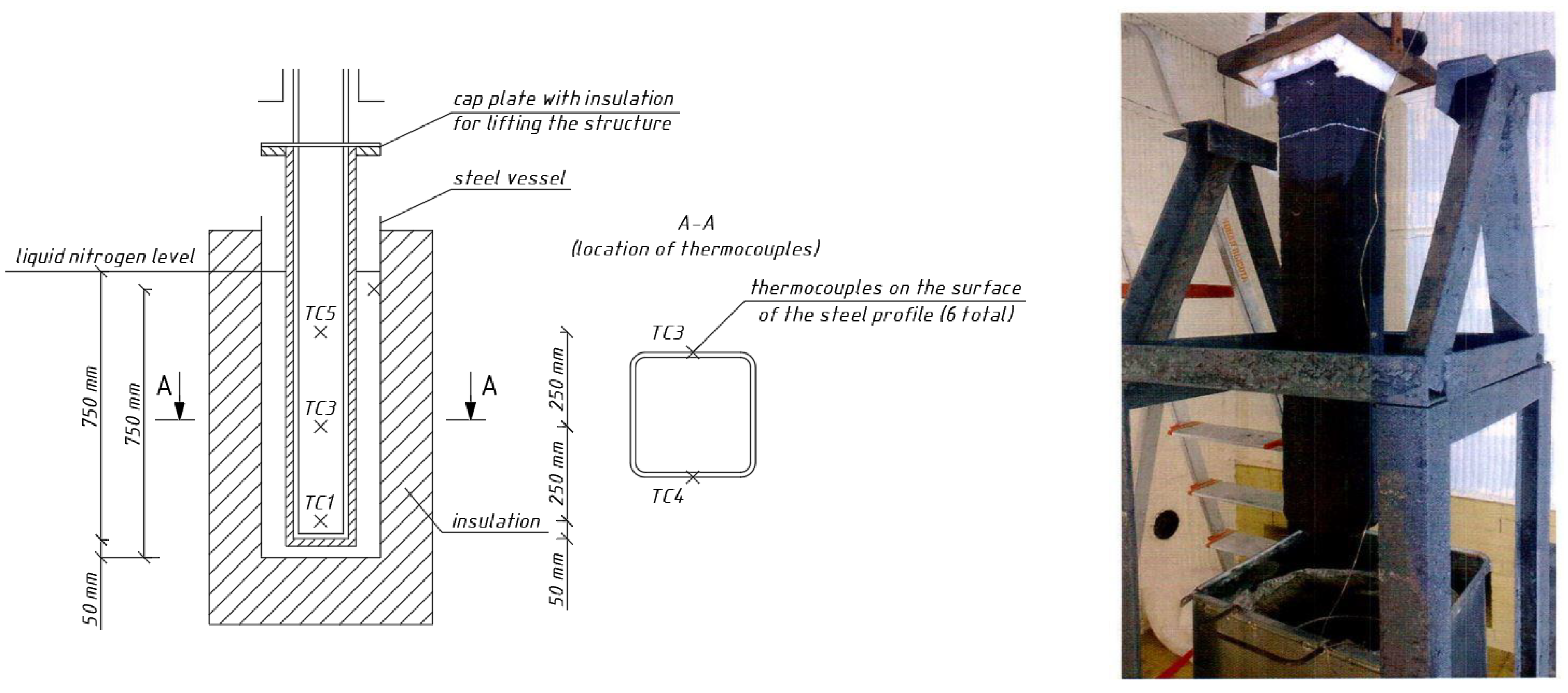
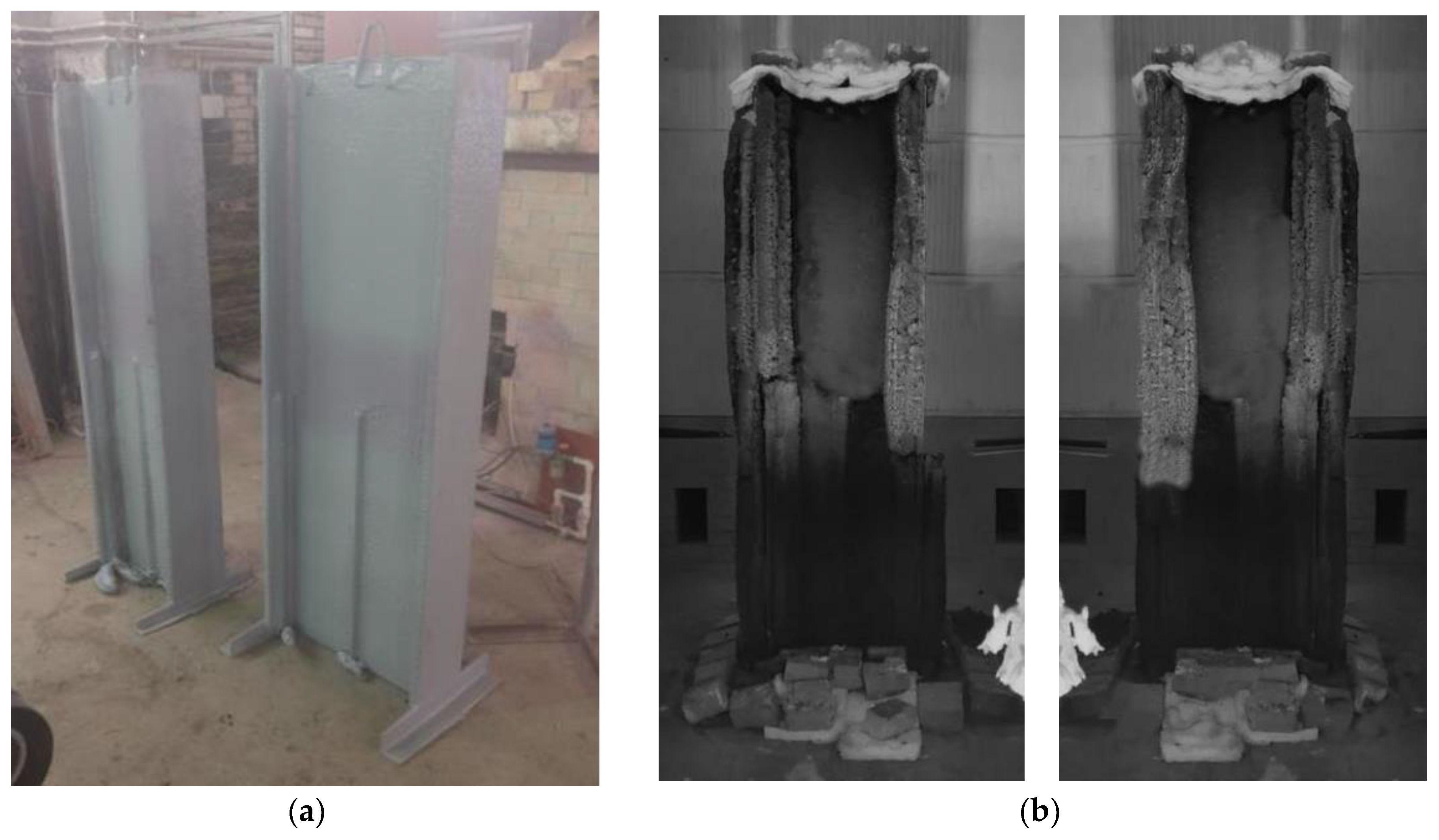
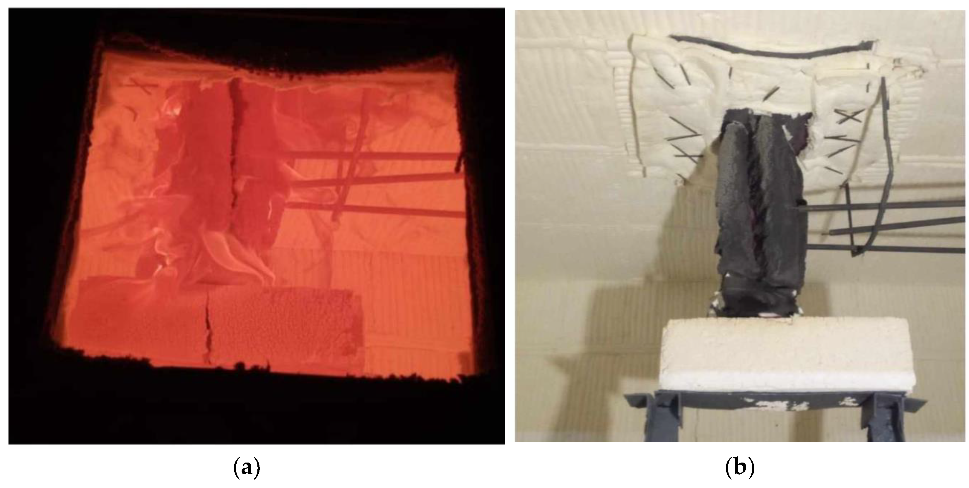
2.1. Experiments on Steel Structures
2.2. Simulation in SP QuickField
- -
- the equation of heat conduction:
- -
- initial condition:
- -
- boundary condition on the outer surface of the inverse heat conduction task at
- -
- boundary condition on the inner surface of the fireproof coating at
- (1)
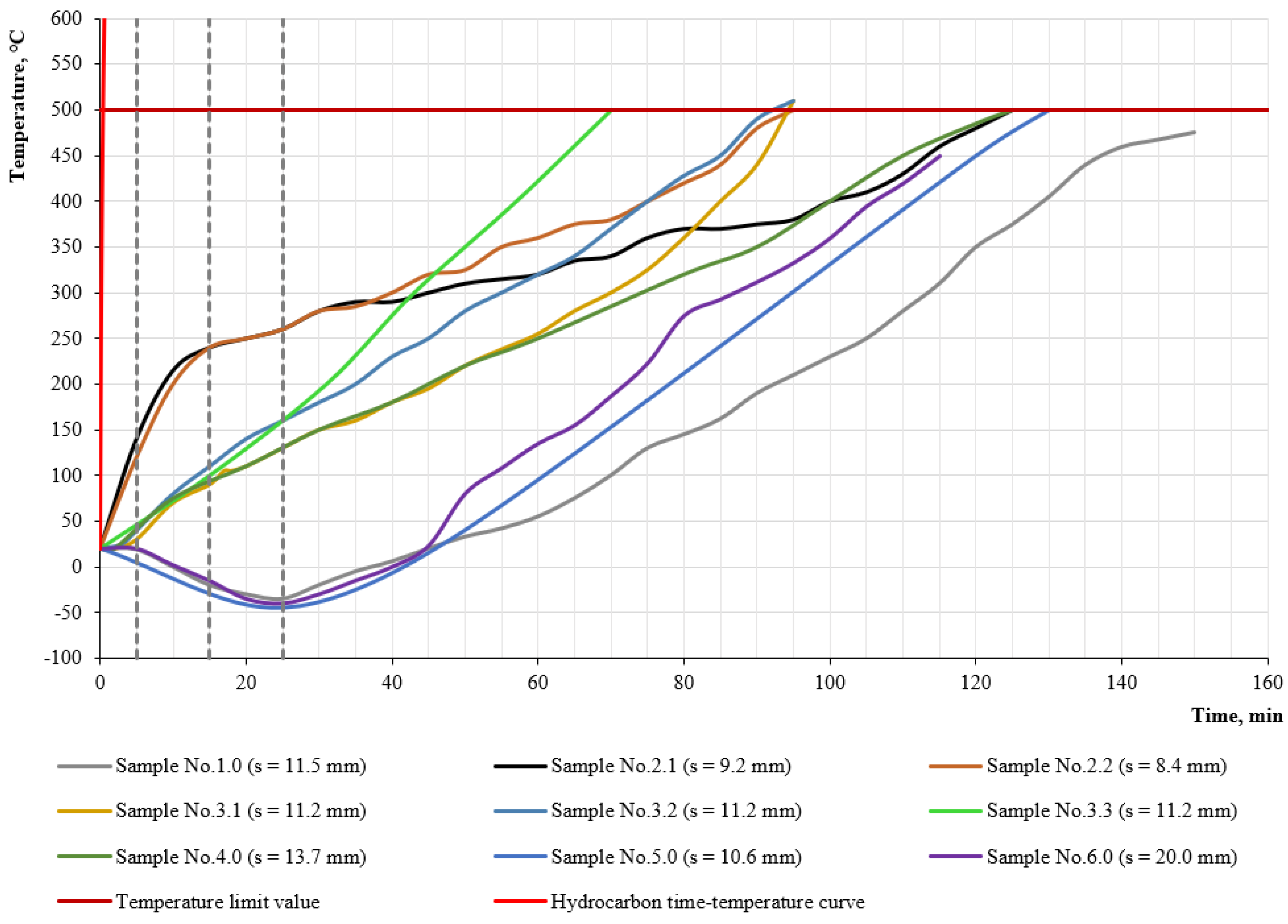
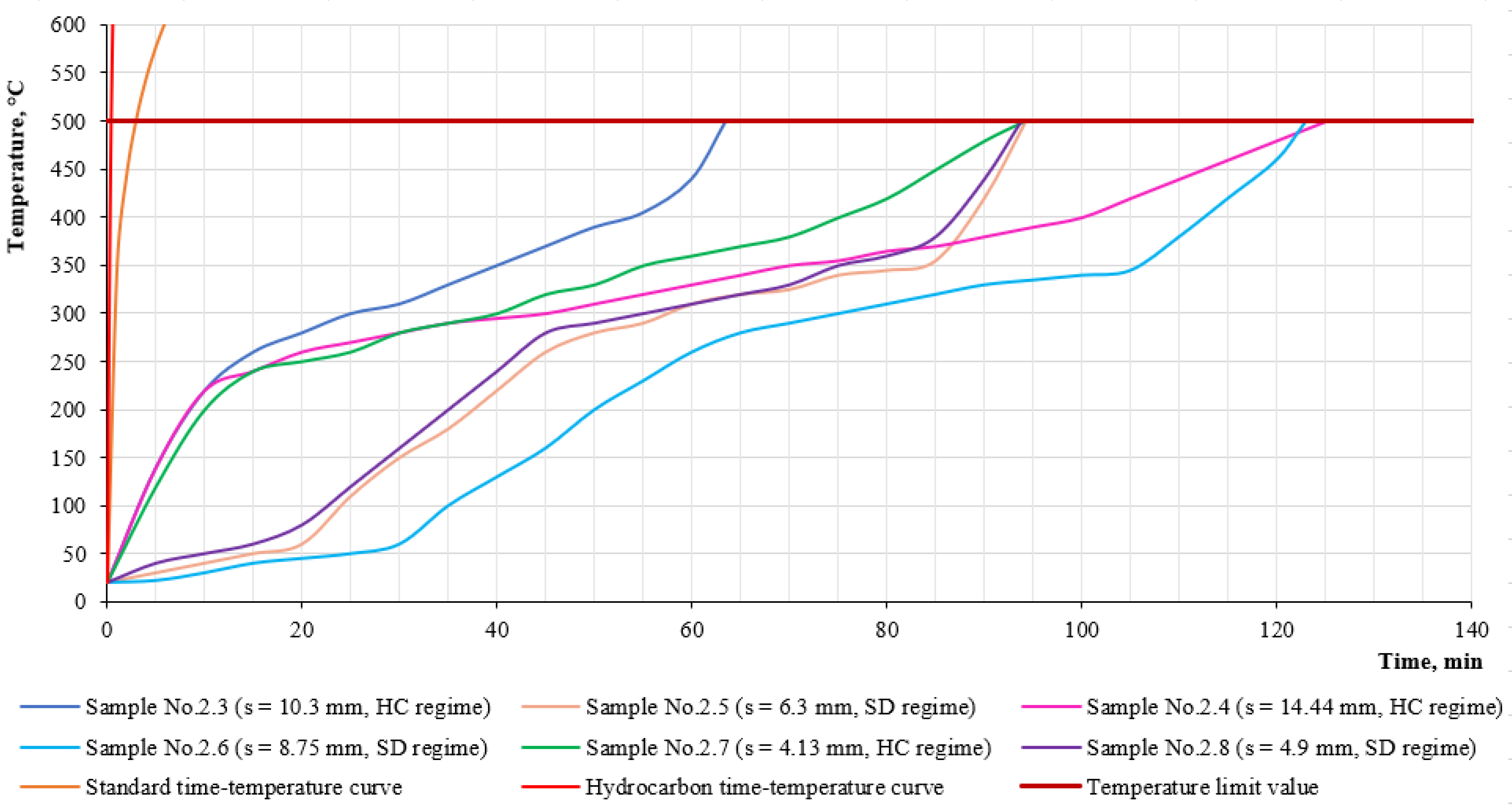
- Analysis of the temperature increase on the steel sample under hydrocarbon and standard fire regimes after the start of fire exposure; during this time, the investigated intumescent coatings are still located on the samples;
- (2)
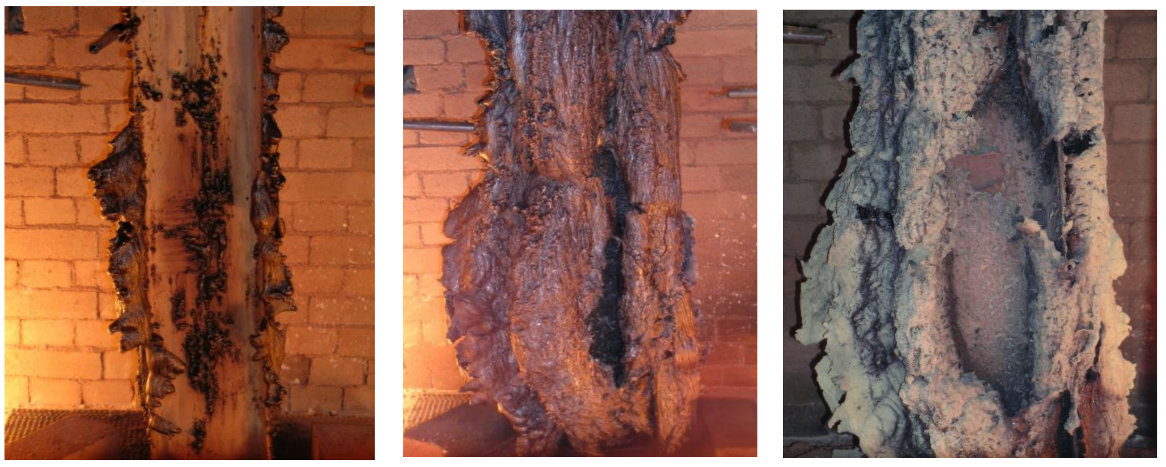
- Analysis of temperature changes on the steel sample under hydrocarbon and standard fire regimes during the last minutes of fire exposure; during this time, a protective layer of 40 mm thick foam coke has already been formed around the samples (for simplicity, the thickness is averaged, and 40 mm is taken as optimal in terms of height and cell distribution).
3. Results and Discussion
3.1. Experimental Results on Steel Structures
3.2. Results of Simulation in SP QuickField
3.3. Discussion
4. Conclusions
Author Contributions
Funding
Institutional Review Board Statement
Informed Consent Statement
Data Availability Statement
Conflicts of Interest
References
- Gorlenko, N.V.; Murzin, M.A. Comparative Analysis of Fire Risks in Coal and Oil and Gas Industries. IOP Conf. Ser. Mater. Sci. Eng. 2019, 687, 066009. [Google Scholar] [CrossRef]
- Makhutov, N.A.; Bolshakov, A.M.; Zakharova, M.I. Possible Scenarios of Accidents in Reservoirs and Pipelines at Low Operating Temperature. Inorg. Mater. 2016, 52, 1498–1502. [Google Scholar] [CrossRef]
- Tong, S.J.; Wu, Z.Z.; Wang, R.J.; Wu, H. Fire Risk Study of Long-Distance Oil and Gas Pipeline Based on QRA. Procedia Eng. 2016, 135, 369–375. [Google Scholar] [CrossRef]
- Ivanov, A.V.; Dali, F.A.; Ivakhnyuk, G.K.; Skripnick, I.L.; Simonova, M.A.; Shikhalev, D.V. Nanostructures Management Technology to Reduce the Fire Risk in the Oil and Gas Industry: Performance, Features and Implementation. J. Appl. Eng. Sci. 2021, 19, 84–91. [Google Scholar] [CrossRef]
- Alam, M.Z.; Sakib, M.N.; Islam, M.; Jalal Uddin, M. Various Risks and Safety Analysis to Reduce Fire in Oil Refinery Plant. IOP Conf. Ser. Mater. Sci. Eng. 2021, 1078, 012028. [Google Scholar] [CrossRef]
- Abdoul Nasser, A.H.; Ndalila, P.D.; Mawugbe, E.A.; Emmanuel Kouame, M.; Paterne, M.A.; Li, Y. Mitigation of Risks Associated with Gas Pipeline Failure by Using Quantitative Risk Management Approach; a Descriptive Study on Gas Industry. J. Mar. Sci. Eng. 2021, 9, 1098. [Google Scholar] [CrossRef]
- Masoumi, Z.; van L. Genderen, J.; Maleki, J. Fire Risk Assessment in Dense Urban Areas Using Information Fusion Techniques. ISPRS Int. J. Geo-Inf. 2019, 8, 579. [Google Scholar] [CrossRef]
- Kodur, V.K.R.; Naser, M.Z. Approach for Shear Capacity Evaluation of Fire Exposed Steel and Composite Beams. J. Constr. Steel Res. 2018, 141, 91–103. [Google Scholar] [CrossRef]
- Gravit, M.; Gumerova, E.; Bardin, A.; Lukinov, V. Increase of Fire Resistance Limits of Building Structures of Oil-and-Gas Complex Under Hydrocarbon Fire. Adv. Intell. Syst. Comput. 2018, 692, 818–829. [Google Scholar] [CrossRef]
- Gravit, M.; Shabunina, D. Structural Fire Protection of Steel Structures in Arctic Conditions. Buildings 2021, 11, 499. [Google Scholar] [CrossRef]
- Elbasuney, S.; Maraden, A. Novel Thermoset Nanocomposite Intumescent Coating Based on Hydroxyapatite Nanoplates for Fireproofing of Steel Structures. J. Inorg. Organomet. Polym. Mater. 2020, 30, 820–830. [Google Scholar] [CrossRef]
- Mahmud, H.M.I.; Mandal, A.; Nag, S.; Moinuddin, K.A.M. Performance of Fire Protective Coatings on Structural Steel Member Exposed to High Temperature. J. Struct. Fire Eng. 2021, 12, 193–211. [Google Scholar] [CrossRef]
- Jiang, S.; Wu, H. An Experimental Investigation on the Fire Resistance of the Integrated Envelope-Fire Protection Material for Steel Buildings. Prog. Steel Build. Struct. 2021, 23, 77–84. [Google Scholar] [CrossRef]
- Gravit, M.; Simonenko, Y.; Yablonskii, L. 3D-Flexible Intumescent Fire Protection Mesh for Building Structures. E3S Web Conf. 2019, 91, 02004. [Google Scholar] [CrossRef]
- Johanna, L.; Judith, K.; Alar, J.; Birgit, M.; Siim, P. Material Properties of Clay and Lime Plaster for Structural Fire Design. Fire Mater. 2021, 45, 355–365. [Google Scholar] [CrossRef]
- Zehfuß, J.; Sander, L.; Schaumann, P.; Weisheim, W. Thermal Material Properties of Fire Protection Materials for Natural Fire Scenarios. Bautechnik 2018, 95, 535–546. [Google Scholar] [CrossRef]
- Gravit, M.V.; Golub, E.V.; Antonov, S.P. Fire Protective Dry Plaster Composition for Structures in Hydrocarbon Fire. Mag. Civ. Eng. 2018, 79, 86–94. [Google Scholar] [CrossRef]
- Zybina, O.; Gravit, M. Intumescent Coatings for Fire Protection of Building Structures and Materials; Springer Series on Polymer and Composite Materials; Springer International Publishing: Cham, Switzerland, 2020. [Google Scholar]
- Kandola, B.K.; Luangtriratana, P.; Duquesne, S.; Bourbigot, S. The Effects of Thermophysical Properties and Environmental Conditions on Fire Performance of Intumescent Coatings on Glass Fibre-Reinforced Epoxy Composites. Materials 2015, 8, 5216–5237. [Google Scholar] [CrossRef]
- Jimenez, M.; Bellayer, S.; Revel, B.; Duquesne, S.; Bourbigot, S. Comprehensive Study of the Influence of Different Aging Scenarios on the Fire Protective Behavior of an Epoxy Based Intumescent Coating. Ind. Eng. Chem. Res. 2013, 52, 729–743. [Google Scholar] [CrossRef]
- Morys, M.; Häßler, D.; Krüger, S.; Schartel, B.; Hothan, S. Beyond the Standard Time-Temperature Curve: Assessment of Intumescent Coatings under Standard and Deviant Temperature Curves. Fire Saf. J. 2020, 112, 102951. [Google Scholar] [CrossRef]
- Yasir, M.; Amir, N.; Ahmad, F.; Ullah, S.; Jimenez, M. Effect of Basalt Fibers Dispersion on Steel Fire Protection Performance of Epoxy-Based Intumescent Coatings. Prog. Org. Coat. 2018, 122, 229–238. [Google Scholar] [CrossRef]
- Gravit, M.; Klementev, B.; Shabunina, D. Fire Resistance of Steel Structures with Epoxy Fire Protection under Cryogenic Exposure. Buildings 2021, 11, 537. [Google Scholar] [CrossRef]
- Andryushkin, A.Y.; Kirshina, A.A.; Kadochnikova, E.N. The Evaluation of the Fire-Retardant Efficiency of Intumescent Coatings of Steel Structures Exposed to High-Temperature Gas Flows. Pozharovzryvobezopasnost/Fire Explos. Saf. 2021, 30, 14–26. [Google Scholar] [CrossRef]
- Mariappan, T.; Kamble, A.; Naik, S.M. An Investigation of Primer Adhesion and Topcoat Compatibility on the Waterborne Intumescent Coating to Structural Steel. Prog. Org. Coat. 2019, 131, 371–377. [Google Scholar] [CrossRef]
- Naik, A.D.; Duquesne, S.; Bourbigot, S. Hydrocarbon Time-Temperature Curve under Airjet Perturbation: An in Situ Method to Probe Char Stability and Integrity in Reactive Fire Protection Coatings. J. Fire Sci. 2016, 34, 385–397. [Google Scholar] [CrossRef]
- Nørgaard, K.P.; Dam-Johansen, K.; Català, P.; Kiil, S. Laboratory and Gas-Fired Furnace Performance Tests of Epoxy Primers for Intumescent Coatings. Prog. Org. Coat. 2014, 77, 1577–1584. [Google Scholar] [CrossRef]
- Nyazika, T.; Jimenez, M.; Samyn, F.; Bourbigot, S. Modeling Heat Transfers across a Silicone-Based Intumescent Coating. J. Phys. Conf. Ser. 2018, 1107, 032012. [Google Scholar] [CrossRef]
- Zeng, Y.; Weinell, C.E.; Dam-Johansen, K.; Ring, L.; Kiil, S. Exposure of Hydrocarbon Intumescent Coatings to the UL1709 Heating Curve and Furnace Rheology: Effects of Zinc Borate on Char Properties. Prog. Org. Coat. 2019, 135, 321–330. [Google Scholar] [CrossRef]
- Gravit, M.; Gumenyuk, V.; Sychov, M.; Nedryshkin, O. Estimation of the Pores Dimensions of Intumescent Coatings for Increase the Fire Resistance of Building Structures. Proc. Procedia Eng. 2015, 117, 119–125. [Google Scholar] [CrossRef]
- Geoffroy, L.; Samyn, F.; Jimenez, M.; Bourbigot, S. Intumescent Polymer Metal Laminates for Fire Protection. Polymer 2018, 10, 995. [Google Scholar] [CrossRef]
- Gravit, M.; Ikhiyanov, N.; Radaev, A.; Shabunina, D. Implementation of Elements of the Concept of Lean Construction in the Fire Protection of Steel Structures at Oil and Gas Facilities. Buildings 2022, 12, 2016. [Google Scholar] [CrossRef]
- Piloto, P.A.G.; Balsa, C.; Santos, L.M.C.; Kimura, É.F.A. Effect of the Load Level on the Resistance of Composite Slabs with Steel Decking under Fire Conditions. J. Fire Sci. 2020, 38, 212–231. [Google Scholar] [CrossRef]
- Gravit, M.; Klimin, N.; Karimova, A.; Fedotova, E.; Dmitriev, I. Fire Resistance Evaluation of Tempered Glass in Software ELCUT. Smart Innov. Syst. Technol. 2021, 220, 523–537. [Google Scholar] [CrossRef]
- Gravit, M.; Lavrinenko, M.; Lazarev, Y.; Rozov, A.; Pavlenko, A. Modeling of Cold-Formed Thin-Walled Steel Profile with the MBOR Fire Protection. Adv. Intell. Syst. Comput. 2021, 1259, 577–592. [Google Scholar] [CrossRef]
- Gravit, M.; Shabunina, D. Numerical and Experimental Analysis of Fire Resistance for Steel Structures of Ships and Offshore Platforms. Fire 2022, 5, 9. [Google Scholar] [CrossRef]
- QuickField. Modeling of Two-Dimensional Fields by the Finite Element Method. Available online: https://quickfield.com/ (accessed on 17 December 2022).
- Schaumann, P.; Tabeling, F.; Weisheim, W. Numerical Simulation of the Heating Behaviour of Steel Profles with Intumescent Coating Adjacent to Trapezoidal Steel Sheets in Fre. J. Struct. Fire Eng. 2016, 7, 158–167. [Google Scholar] [CrossRef]
- Barthelemy, B.; Kruppa, J. Fire Resistance of Building Structures; Stroyizdat: Moscow, Russia, 1985; p. 216. [Google Scholar]
- Gravit, M.; Shabunina, D.; Antonov, S.; Danilov, A. Thermal Characteristics of Fireproof Plaster Compositions in Exposure to Various Regimes of Fire. Buildings 2022, 12, 630. [Google Scholar] [CrossRef]
- API 2218. Recommended Practices in Petroleum and Petrochemical Processing Plants Structural Fireproofing. Available online: https://www.brindleyengineering.com/wp-content/uploads/2023/01/API-2218-Fireproofing-case-study.pdf (accessed on 3 September 2023).
- 42. SP 4.13130.2013; Systems of Fire Protection. Restriction of Fire Spread at Object of Defense. Requirements to Special Layout and Structural Decisions. Ministry of Emergency of Russia: Moscow, Russia, 2013; 125p. Available online: https://www.admhimki.ru/media/eds/elements/f9f927cb-9929-43ae-be40-fe241849adf0.pdf?ysclid=lmz083d3ki769929025 (accessed on 11 January 2023).
- EN 1363-2:1999; Fire Resistance Tests—Part 2: Alternative and Additional Procedures. British Standards Institution: London, UK, 1999; 16p. Available online: https://nd.gostinfo.ru/document/6239985.aspx (accessed on 2 September 2023).
- GOST 53295-2009; Fire Retardant Compositions for Steel Constructions. General Requirement. Method for Determining Fire Retardant Efficiency. FGU VNIIPO of EMERCOM of Russia: Moscow, Russia, 2010; 14p. Available online: https://technologygroup.ru/images/documents/gost/53295-2009.pdf (accessed on 6 February 2023).
- ISO 834-75; Elements of Building Constructions. Fire-Resistance Test Methods. General Requirements. International Organ-ization for Standardization: New York, NY, USA, 1975; 16p. Available online: https://docs.cntd.ru/document/9055248 (accessed on 2 September 2023).
- Eurocode 3: Design of Steel Structures—Part 1–2: General Rules Structural Fire Design. Available online: https://www.phd.eng.br/wp-content/uploads/2015/12/en.1993.1.2.2005.pdf (accessed on 21 January 2023).
- GOST 8639-82; Square Steel Pipes. FGUP IPC Publishing House of Standards: Moscow, Russia, 1982; 7p. Available online: https://files.stroyinf.ru/Data/38/3826.pdf?ysclid=lmz0pm3655454170927 (accessed on 4 February 2023).
- GOST 57837-2017; Hot-Rolled Steel I-Beams with Parallel Edges of Flanges. Specifications. JSC SIC Construction: Moscow, Russia, 2017; 44p. Available online: https://docs.cntd.ru/document/1200157342 (accessed on 24 January 2023).
- Wang, J.X.; Liu, K.; Zhao, C.S.; Wang, Z.L. Research on the Theoretical Calculation Method of Dynamic Response of the Stiffened Plate on the Accommodation of Offshore Platforms under Blast. Chuan Bo Li Xue/J. Sh. Mech. 2020, 24. [Google Scholar] [CrossRef]
- Kim, T.K.; Kim, S.K.; Lee, J.M. Dynamic Response of Drill Floor Considering Propagation of Blast Pressure Subsequent to Blowout. Appl. Sci. 2020, 10, 8841. [Google Scholar] [CrossRef]
- Kung, F.; Yang, M.C. Improvement of the Heat-Dissipating Performance of Powder Coating with Graphene. Polymers 2020, 12, 1321. [Google Scholar] [CrossRef]
- GOST 27772-2015; Rolled Products for Structural Steel Constructions. General Specifications. SE UkrSTC Energostal: Kharkov, Ukraine, 2015; 30p. Available online: https://docs.cntd.ru/document/1200133727 (accessed on 4 February 2023).
- EN 1991-1-2; Eurocode 1: Actions on Structures-Part 1–2: General Actions-Actions on Structures Exposed to Fire. European Committee for Standardization: Brussels, Belgium, 2002; 61p. Available online: https://www.phd.eng.br/wp-content/uploads/2015/12/en.1991.1.2.2002.pdf (accessed on 25 August 2023).
- Markus, E.S.; Snegirev, A.Y.; Kuznetsov, E.A. Numerical Simulation of a Fire Using Fire Dynamics; St. Petersburg Polytech-Press: St. Petersburg, Russia, 2021; p. 175. [Google Scholar]


| Sample | Profile | Height, mm | Section Ratio, mm−1 [46] | Average Thickness, mm | Regime |
|---|---|---|---|---|---|
| Sample No. 1.0 | □ 100 × 8 mm [47] | 2700 | 134 | 11.50 | cryogenics + hydrocarbon regime |
| Sample No. 2.1 | I 50B2 [48] | 1700 | 172 | 9.20 | hydrocarbon regime |
| Sample No. 2.2 | I 50B2 | 1700 | 172 | 8.40 | hydrocarbon regime |
| Sample No. 2.3 | I 14B1 | 1700 | 172 | 10.30 | hydrocarbon regime |
| Sample No. 2.4 | I 14B1 | 1700 | 172 | 14.44 | hydrocarbon regime |
| Sample No. 2.5 | I 14B1 | 1700 | 172 | 6.30 | standard regime |
| Sample No. 2.6 | I 14B1 | 1700 | 172 | 8.75 | standard regime |
| Sample No. 2.7 | I 50B2 | 1700 | 172 | 4.13 | hydrocarbon regime |
| Sample No. 2.8 | I 50B2 | 1700 | 172 | 4.00 | standard regime |
| Sample No. 3.1 | I 50B2 | 1700 | 172 | 11.20 | hydrocarbon regime |
| Sample No. 3.2 | I 50B2 | 1700 | 172 | 11.20 | hydrocarbon regime |
| Sample No. 3.3 | I 50B2 | 1700 | 172 | 11.20 | hydrocarbon regime |
| Sample No. 4.0 | I 30K1 | 2700 | 159 | 13.70 | hydrocarbon regime |
| Sample No. 5.0 | I 30K1 | 2700 | 159 | 10.60 | cryogenics + hydrocarbon regime |
| Sample No. 6.0 | ∅100 × 8 | 2700 | 136 | 20.00 | cryogenics + hydrocarbon regime |
| Name of the Value | Value | Information Source |
|---|---|---|
| Convection heat transfer coefficient at hydrocarbon temperature regime, W/(m2 · K) | 50 | [53] |
| Convection heat transfer coefficient at standard temperature regime, W/(m2 · K) | 25 | [53] |
| Emissivity of steel | 0.6 | [54] |
| Initial ambient temperature, °C | 20 | - |
| Time step for calculating the temperature gradient of the structure, seconds | 60 | - |
| Structural Elements | λ, W/(m·K) | Cp, J/(kg·K) | ρ, kg/m3 | ||||
|---|---|---|---|---|---|---|---|
| 20 °C | 100 °C | 300 °C | 20 °C | 100 °C | 300 °C | ||
| Steel | 49 | 25 | 25 | 469 | 670 | 670 | 7800 |
| Air | 0.0321 | 0.0915 | 0.0915 | 1009 | 1210 | 1210 | 1.275 |
| Sample No. 1.0 | 0.08 | 0.07 | 0.07 | 1300 | 1300 | 1300 | 1200 |
| Samples No. 2.1–2.8 | 0.07 | 0.08 | 0.08 | 600 | 850 | 900 | 700 |
| Samples No. 3.1–3.3 | 0.20 | 0.17 | 0.15 | 1050 | 1050 | 1050 | 1220 |
| Sample No. 4.0 | 0.15 | 0.10 | 0.09 | 800 | 800 | 800 | 1000 |
| Sample No. 5.0 | 0.15 | 0.10 | 0.09 | 1000 | 1030 | 1080 | 1200 |
| Sample No. 6.0 | 1.8 | 1.8 | 1.8 | 1100 | 1100 | 1100 | 700 |
| Sample | Profile | Section Ratio, mm−1 [46] | Average Thickness, mm | Cryogenic Exposure | Fire Protection Effectiveness, min |
|---|---|---|---|---|---|
| Sample No. 1.0 | □ 100 × 8 mm [47] | 134 | 11.50 | + | 120 |
| Sample No. 2.1 | I 50B2 [48] | 172 | 9.20 | − | 120 |
| Sample No. 2.2 | I 50B2 | 172 | 8.40 | − | 90 |
| Sample No. 2.3 | I 14B1 | 172 | 10.30 | − | 60 |
| Sample No. 2.4 | I 14B1 | 172 | 14.44 | − | 120 |
| Sample No. 2.5 | I 14B1 | 172 | 6.30 | − | 90 |
| Sample No. 2.6 | I 14B1 | 172 | 8.75 | − | 12- |
| Sample No. 2.7 | I 50B2 | 172 | 4.13 | − | 90 |
| Sample No. 2.8 | I 50B2 | 172 | 4.00 | − | 90 |
| Sample No. 3.1 | I 50B2 | 172 | 11.20 | − | 90 |
| Sample No. 3.2 | I 50B2 | 172 | 11.20 | − | 90 |
| Sample No. 3.3 | I 50B2 | 172 | 11.20 | − | 60 |
| Sample No. 4.0 | I 30K1 | 159 | 13.70 | − | 120 |
| Sample No. 5.0 | I 30K1 | 159 | 10.60 | + | 90 |
| Sample No. 6.0 | ∅100 × 8 | 136 | 20.00 | + | 90 |
| T, °C | 100 | 200 | 300 | 400 | 500 | 600 | 700 | 800 | 900 | 1000 | 1100 |
|---|---|---|---|---|---|---|---|---|---|---|---|
| λ, W/K·m | 0.07 | 0.071 | 0.072 | 0.073 | 0.074 | 0.08 | 0.09 | 0.10 | 0.11 | 0.13 | 0.15 |
| C, J/kg·m | 800 | 825 | 850 | 880 | 900 | 925 | 955 | 980 | 990 | 1000 | 1010 |
| T, °C | 100 | 200 | 300 | 400 | 500 | 600 | 700 | 800 | 900 | 1000 | 1100 |
|---|---|---|---|---|---|---|---|---|---|---|---|
| λ, W/K·m | 0.12 | 0.09 | 0.07 | 0.055 | 0.05 | 0.048 | 0.046 | 0.046 | 0.048 | 0.05 | 0.055 |
| C, J/kg·m | 700 | 745 | 780 | 830 | 850 | 875 | 915 | 950 | 990 | 1000 | 1020 |
| T, °C | 100 | 200 | 300 | 400 | 500 | 600 | 700 | 800 | 900 | 1000 | 1100 |
|---|---|---|---|---|---|---|---|---|---|---|---|
| λ, W/K·m | 0.15 | 0.15 | 0.1 | 0.05 | 0.05 | 0.05 | 0.08 | 0.14 | 0.2 | 0.25 | 0.3 |
| C, J/kg·m | 600 | 600 | 600 | 400 | 200 | 200 | 200 | 200 | 300 | 600 | 900 |
| T, °C | 100 | 200 | 300 | 400 | 500 | 600 | 700 | 800 | 900 | 1000 | 1100 |
|---|---|---|---|---|---|---|---|---|---|---|---|
| λ, W/K·m | 0.04 | 0.05 | 0.05 | 0.05 | 0.06 | 0.08 | 0.11 | 0.14 | 0.16 | 0.17 | 0.19 |
| C, J/kg·m | 820 | 840 | 860 | 890 | 900 | 930 | 980 | 1040 | 1120 | 1200 | 1300 |
| T, °C | 100 | 200 | 300 | 400 | 500 | 600 | 700 | 800 | 900 | 1000 | 1100 |
|---|---|---|---|---|---|---|---|---|---|---|---|
| λ, W/K·m | 0.1 | 0.09 | 0.089 | 0.09 | 0.1 | 0.11 | 0.12 | 0.13 | 0.15 | 0.17 | 0.2 |
| C, J/kg·m | 1030 | 1050 | 1080 | 1090 | 1100 | 1120 | 1140 | 1150 | 1170 | 1180 | 1200 |
| T, °C | 100 | 200 | 300 | 400 | 500 | 600 | 700 | 800 | 900 | 1000 | 1100 |
|---|---|---|---|---|---|---|---|---|---|---|---|
| λ, W/K·m | 0.14 | 0.12 | 0.11 | 0.09 | 0.08 | 0.08 | 0.09 | 0.12 | 0.16 | 0.20 | 0.25 |
| C, J/kg·m | 800 | 815 | 830 | 840 | 850 | 860 | 870 | 880 | 890 | 900 | 910 |
Disclaimer/Publisher’s Note: The statements, opinions and data contained in all publications are solely those of the individual author(s) and contributor(s) and not of MDPI and/or the editor(s). MDPI and/or the editor(s) disclaim responsibility for any injury to people or property resulting from any ideas, methods, instructions or products referred to in the content. |
© 2023 by the authors. Licensee MDPI, Basel, Switzerland. This article is an open access article distributed under the terms and conditions of the Creative Commons Attribution (CC BY) license (https://creativecommons.org/licenses/by/4.0/).
Share and Cite
Gravit, M.; Shabunina, D.; Shcheglov, N. Thermal Characteristics of Epoxy Fire-Retardant Coatings under Different Fire Regimes. Fire 2023, 6, 420. https://doi.org/10.3390/fire6110420
Gravit M, Shabunina D, Shcheglov N. Thermal Characteristics of Epoxy Fire-Retardant Coatings under Different Fire Regimes. Fire. 2023; 6(11):420. https://doi.org/10.3390/fire6110420
Chicago/Turabian StyleGravit, Marina, Daria Shabunina, and Nikita Shcheglov. 2023. "Thermal Characteristics of Epoxy Fire-Retardant Coatings under Different Fire Regimes" Fire 6, no. 11: 420. https://doi.org/10.3390/fire6110420