Article

Simulation of Thermomechanical Coupling and Evaluation of the Fire Resistance for the Joints of Fabricated Frame Tunnel

1
School of Civil Engineering and Architecture, Guangxi University, Nanning 530004, China
2
Key Laboratory of Disaster Prevention and Structural Safety, Nanning 530004, China
3
Hunan Communications Polytechnic, College of Architectural Engineering, Changsha 410132, China
4
Changsha Road and Bridge Construction Co., Ltd., Changsha 410205, China
5
China Construction Fourth Engineering Division Corp. Ltd., Guangzhou 510665, China
*
Author to whom correspondence should be addressed.
Submission received: 22 October 2022 / Revised: 16 December 2022 / Accepted: 18 December 2022 / Published: 21 December 2022
(This article belongs to the Special Issue Advance in Tunnel Fire Research)

Abstract

:
Fire in a tunnel will deteriorate the mechanical properties of the tunnel. For fabricated tunnels formed by splicing prefabricated components through joints, under the high temperature of a fire, the rapid degradation of the bearing capacity of the joints can easily lead to tunnel damage. In this study, a new type of joint (bolt-pin joints (BPJ)) for prefabricated frame tunnels is proposed. To investigate the fire resistance of the new joint and the other three fabricated frame tunnel joints (including mortise joints (MJ), bolt-mortise joints (BMJ), and pin joints (PJ)), a three-dimensional solid model of four types of fabricated frame tunnel joints is established using the finite element calculation software ABAQUS. According to the standard European HC curve, the heat transfer characteristics of the joint model are analyzed, the temperature distribution law of the joint under fire is studied, and the flexural bearing performance and deformation characteristics of the joint before and after the fire are discussed, as well as the influence of the initial axial force on the flexural bearing capacity and the opening of the joint under fire. The analysis result shows that the vertical peak load of the BPJ is higher than that of the other three joints at room temperature. Under the combined action of the pin and bolts and the tongue groove, the vertical peak load of the joints can be effectively increased and the midspan vertical displacement can be reduced. The decrease degree of the vertical peak load of the MJ and BMJ under fire exposure is greater than that of the other two joints, and the opening of the BPJ is 19 mm, which is much smaller than that of the other three joints. When the initial axial force is increased, the openings of the four joints under fire exposure are reduced, the vertical peak loads of the PJ and BPJ are increased, and the vertical peak loads of the MJ and BMJ are not significantly increased. Overall, the BPJ demonstrates better fire resistance.

1. Introduction

Tunnels are narrow and closed relative to aboveground structures, and continuous high temperature in tunnels during a fire causes serious damage to the tunnel lining. For example, in 1996, the tunnel lining was severely damaged in the Channel Tunnel between England and France in a fire, and the most serious damage was that the spalling depth of the original 45 cm thick lining segment concrete reached 40 cm [1,2]. In 1999, the Mont Blanc fire at the France–Italy border caused local concrete peeling of the tunnel vault [3]. In 2011, a large amount of concrete on the side and top of the tunnel spalled off in the fire of the Xinqidaoliang Tunnel in China [4,5]. In 2019, the Limaoling Tunnel facilities were severely damaged by scorching the tunnel vault and detaching concrete blocks in a fire. After fire exposure, the damage to a tunnel greatly reduces the bearing capacity of the tunnel lining. Therefore, it is of great significance to carry out research on the bearing capacity of tunnel structures under fire exposure for tunnel fire prevention and disaster resistance.
In the context of green and low-carbon development, industrial construction is an important direction and path for the development of tunnel engineering. As a new type of tunnel construction method in industrial construction, fabricated frame tunnels have the characteristics of high utilization of underground space, fast construction speed, small disturbance to the environment, and reliable quality. This approach is very popular in the fields of municipal tunnels, underground passages, and multipurpose networks for underground pipelines in cities [6]. However, the fabricated frame tunnel lining is a structure connected by various joints. The lining structure is considered a discontinuous body, which makes the mechanical behavior of the tunnel structure more complicated [7,8]. Joints are the weakest part of a fabricated tunnel. The deterioration of joint performance after a fire will reduce the bearing capacity of the tunnel and even cause structural failure. Therefore, the bearing capacity performance of fabricated frame tunnel joints under fire is the focus of this research.
Many scholars have conducted research on the mechanical properties of tunnels under fire exposure with immersed tunnels and shield tunnels as objects. For example, for immersed tunnels, Lin [9] carried out a fire test through immersed tunnels with a scale of 1:5 and studied the characteristics of the temperature distribution, degree of concrete spalling, and crack distribution of immersed tube tunnels under high-temperature conditions. Duan [10] carried out a large-scale fire test of an immersed tunnel and found that, under the protection of a fire-resistive coating, the deformations of the tunnel were small, but the cracking of the tunnel concrete was very serious on the outside of the tunnel. Guo [11] studied the temperature in the thickness direction of the immersed tunnel under fire by a numerical simulation method. Immersed tunnels are quite different from prefabricated tunnels in terms of structural type, stress characteristics, and construction. In recent years, many scholars have carried out research on the mechanical properties of shield tunnels at high temperatures. For example, Yan [12,13,14] carried out a fire-resistance test of a segment joint with a shallow concave–convex tenon joint structure on a scale of 1:3 and studied the effect of the change in the joint performance on the lining performance of the shield tunnel under high-temperature conditions. Ye [15] carried out fire tests on seven groups of full-scale shield tunnel segment specimens and studied the effects of different fire types and different sealing settings on the mechanical properties of shield tunnel segments under fire and high temperatures. Guo [16] and Yin [17] carried out fire tests on joint specimens of reduced-scale lining with installation errors and studied the lining of shield tunnels under the action of high temperatures due to the apparent characteristics, temperature field distribution, and deformation response of segments. To study the temperature distribution law of the composite segment under fire, Zhang [18] used the finite element calculation software ABAQUS to establish a three-dimensional model of a shield tunnel with an inclined bolt joint. Hua [19] considered the effect of geologic conditions of soil–structure interactions on the fire behavior of tunnels, simulated the fire performance of the lining sections during the heating and cooling, and compared the deformation and internal force caused by the fire in the tunnel sections. Zhang [20] conducted thermal–mechanical coupling analysis of fabricated tunnels. The study found that thermal stress concentration is likely to occur at the corners where the top plate is connected to the middle wall and sidewall. However, the effect of seams was not considered in the numerical simulation.
However, for fabricated frame tunnels, the structural section is usually rectangular. This type of tunnel joint has various types and is usually equipped with connecting components such as bolts and pins to improve the flexural behavior and the shear behavior of the joints. The mechanical characteristics of these joints after fire exposure are different from those of a circular tunnel. There are few studies on the high-temperature mechanical properties of this type of fabricated frame tunnel joint. Therefore, based on the existing joints, this study proposes the design of a new type of joint (bolt-pin joint) for fabricated rectangular tunnels. Taking the bolt-pin joint and three other kinds of fabricated frame tunnel joints (mortise joints, bolt-mortise joints, and pin joints) as research objects, this study establishes three-dimensional solid models of four types of fabricated frame tunnel joints. This study verifies the reliability of the modeling in combination with the existing experimental research results. First, the flexural bearing performance and deformation characteristics of four fabricated frame tunnel joints at room temperature are studied. Second, according to the standard European HC curve, the joint model’s heat transfer characteristics are analyzed and the temperature distribution law of the joint under fire is studied. Finally, the flexural bearing performance and deformation characteristics of the joint before and after the fire are discussed, as well as the influence of the initial axial force on the flexural bearing capacity and the joint’s opening under fire.

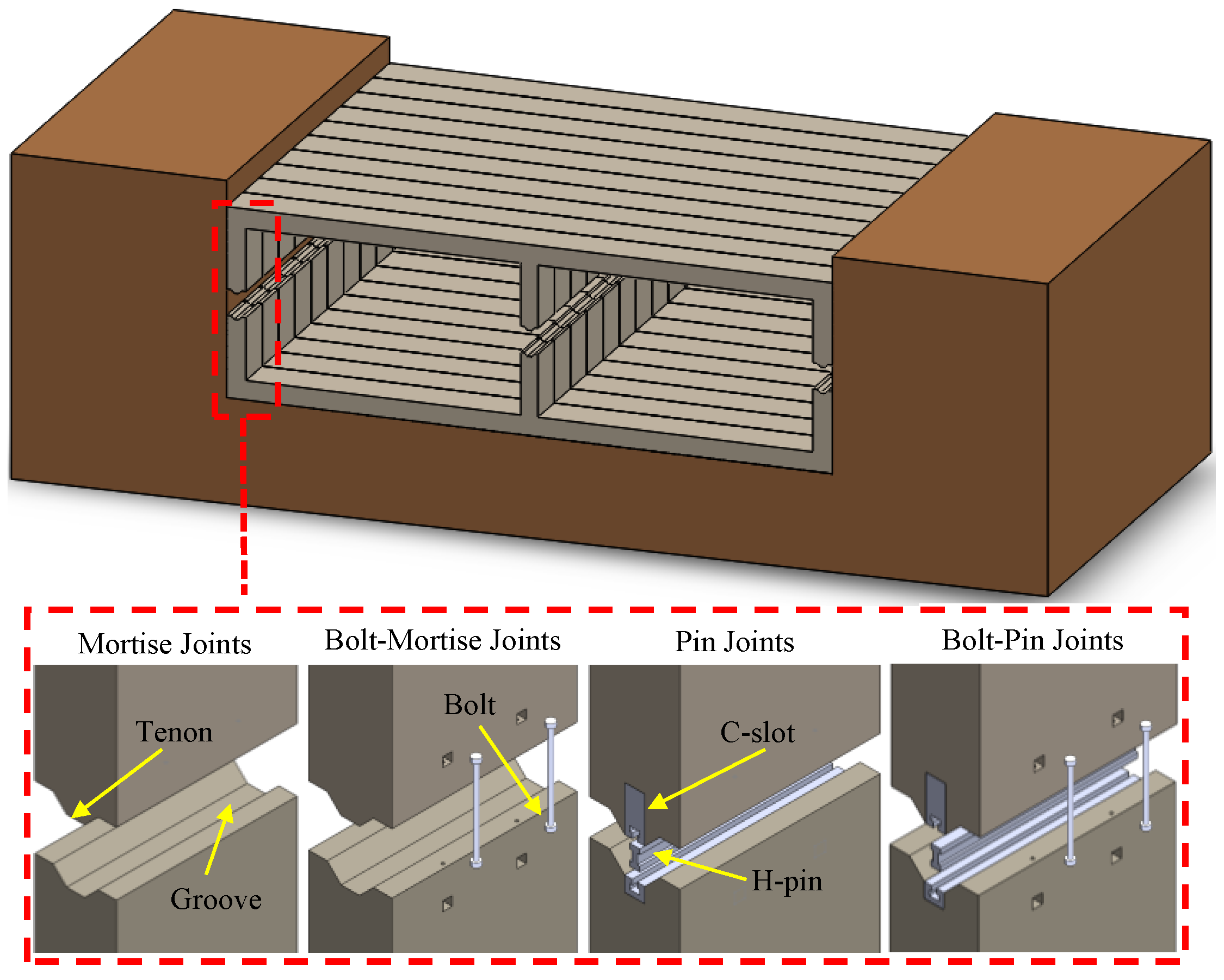
2. Fabricated Frame Tunnel Joints

The structural form and the stress condition of fabricated frame tunnels are significantly different from those of circular tunnels, and rectangular fabricated tunnels have large spans and heavy single-piece components. Therefore, the joints of rectangular tunnels require better mechanical properties. The types of annular joints of fabricated frame tunnels can be summarized as mortise joints, steel sleeve joints, and steel box joints. Among them, mortise joints are composed of tenons and grooves, which produce a certain occlusal effect under the action of axial pressure. The concave–convex occlusal structure can not only resist shearing force but also increase the overall rigidity of the structural joint. It is a relatively common assembly method at present. This study mainly discusses the mechanical properties of four types of fabricated frame tunnel joints, including MJ, BMJ, PJ, and BPJ, at room temperature and under fire conditions, as shown in Figure 1.

2.1. Establishment of the Numerical Simulation Model

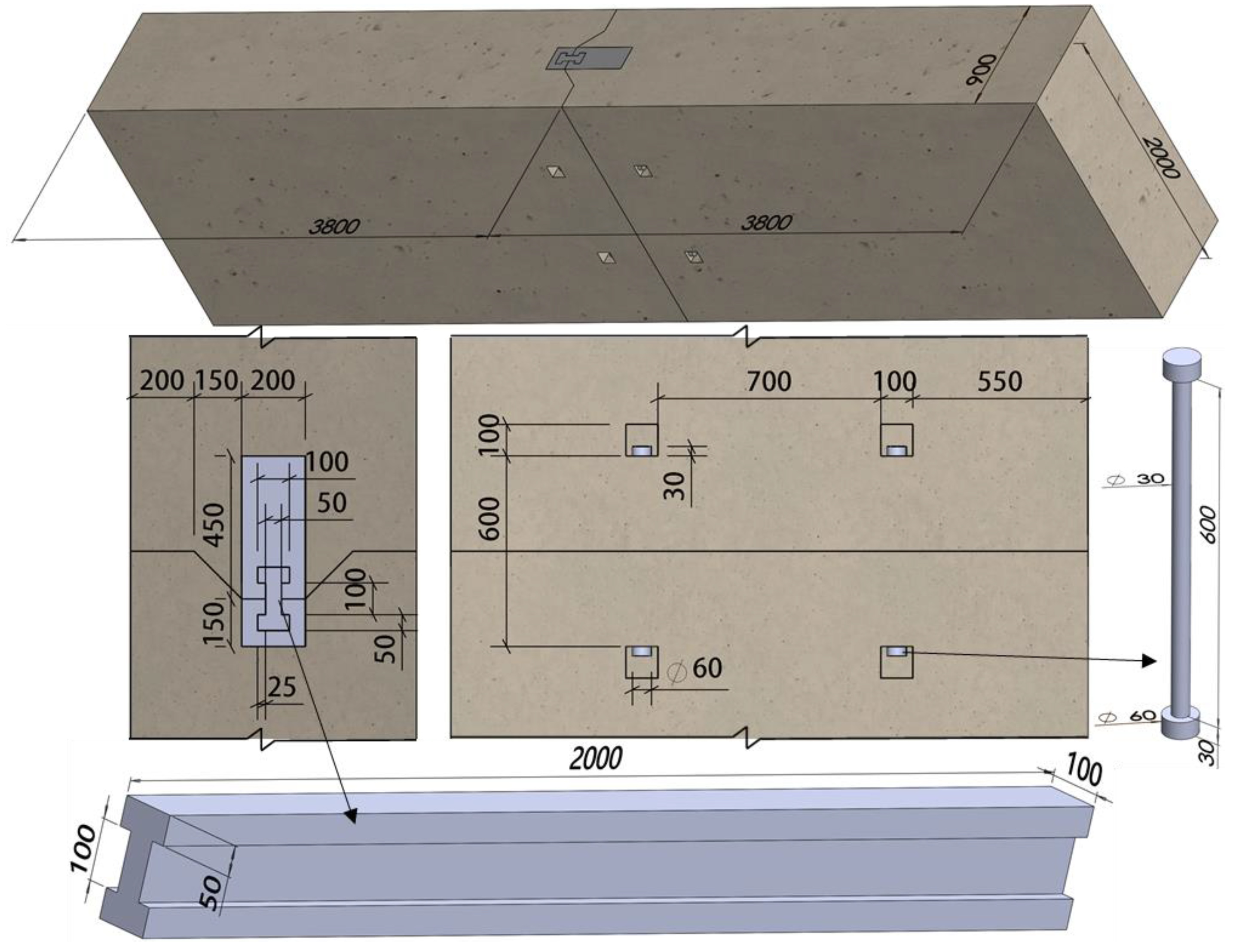
2.1.1. Joint Construction and Dimensions

The numerical simulation model of the fabricated frame tunnel joint is 3800 mm long, 2000 mm wide, and 900 mm thick. The detailed dimensions of the BPJ are shown in Figure 2.

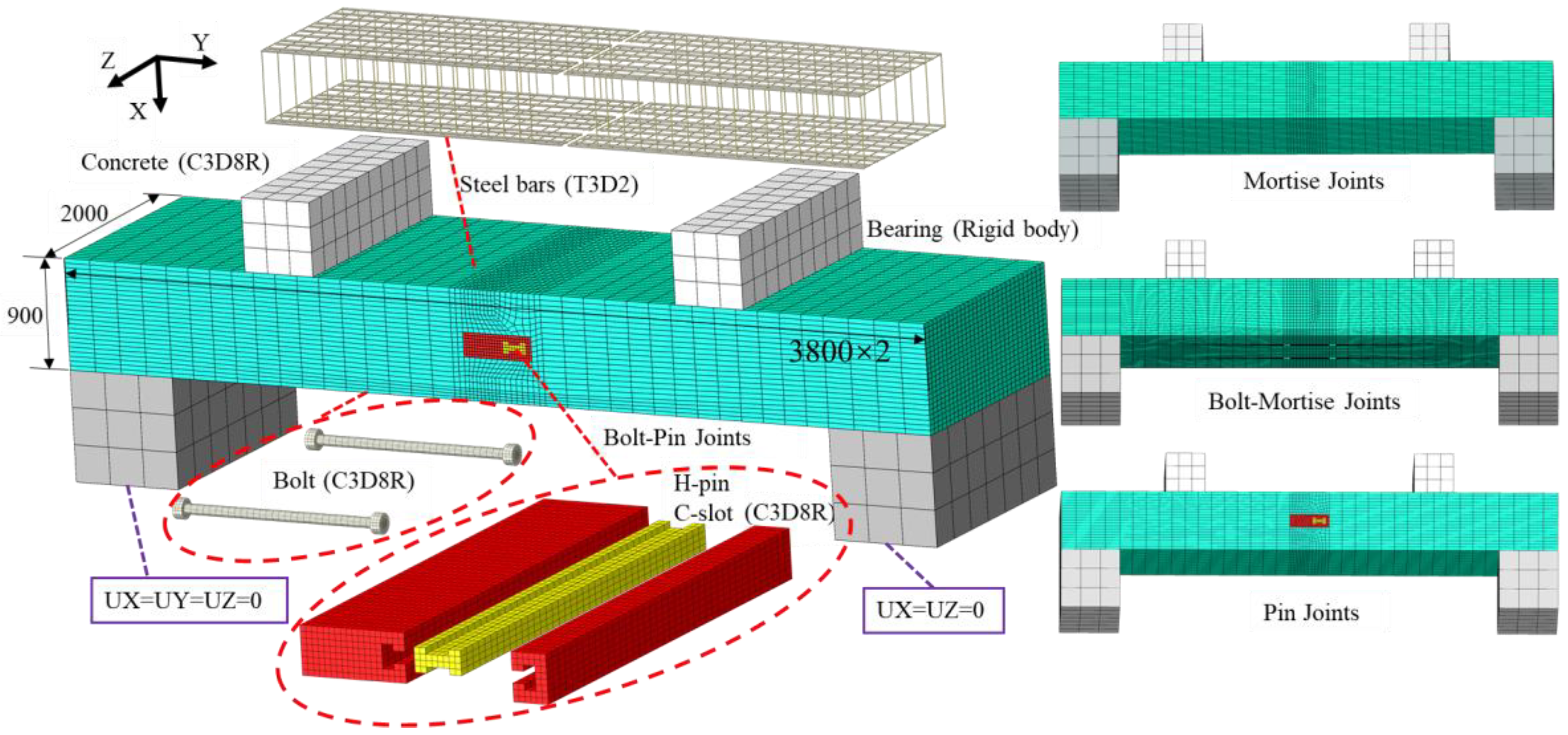
2.1.2. Meshing and Contact Properties

Different element types are used in the numerical simulation. The 8-node linear heat transfer brick elements (DC3D8) and 2-node heat transfer link elements (DC1D2) can effectively reflect the heat transfer. The 8-node 6-facet reduced integral elements (C3D8R) are more accurate in solving the displacement, and the analysis accuracy will not be affected when the mesh is deformed. The 2-node linear 3-D truss elements (T3D2) can effectively reflect the change of the axial stress of the element and is suitable for simulating steel bar. Therefore, in the process of the temperature field calculation, DC3D8 is used to simulate the concrete joints, bolts, H-pin, and C-slot. The steel bars are modeled by DC1D2. In the process of the force-field calculation, the steel bars are modeled using T3D2, and the other parts adopt C3D8R. The meshing of the joint is shown in Figure 3.
The contact relationship between a steel bar and the concrete is set as an embedded contact. Surface-to-surface contacts are used at the concrete-to-concrete, concrete-to-bolt, H-pin-to-C-slot, and C-slot-to-C-slot interfaces, which simulate the normal and tangential contacts between faces. The friction coefficient between the bolt surface and the concrete channel is taken as 0.6, and that between the tenon and the groove surface concrete is taken as 0.3. The tangential behavior at the interface between H-pin and C-slot and between C-slot and C-slot is set to frictionless [6]. Since the nut is always in a tightened state in practice, the contact with the concrete is simplified as a tie. The contact between the outer surface of the C-slot and the concrete is set as a tie.

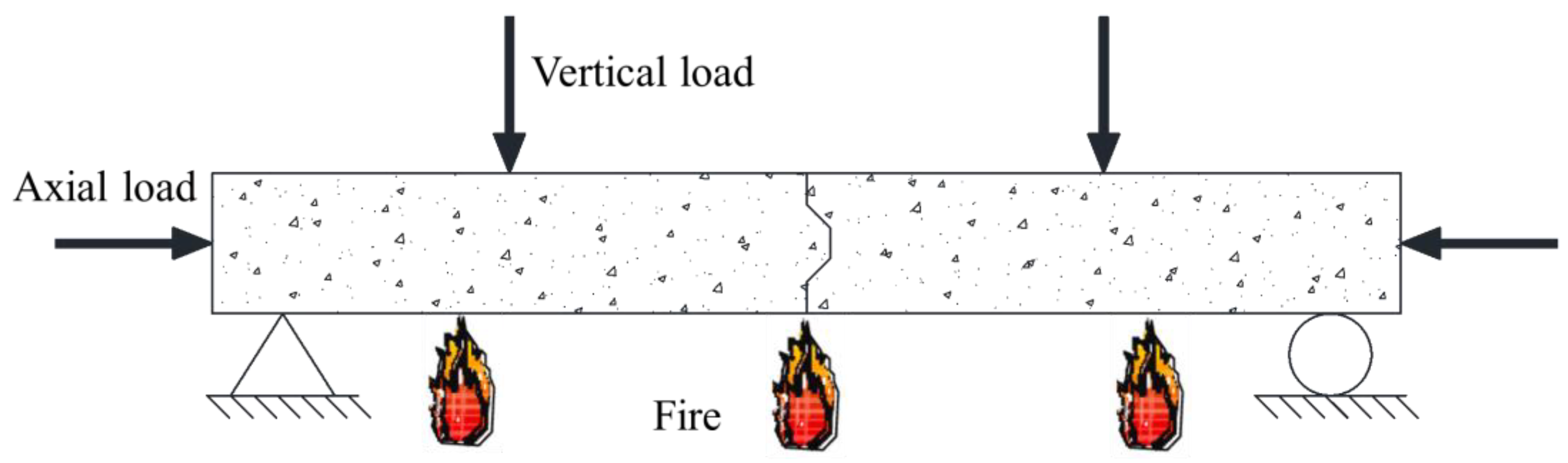
2.1.3. Boundary Conditions and Loading Methods

One end of the boundary conditions of the bearing is UX = UY = UZ = 0 and the other is UX = UZ = 0. The bearing and loading pads are set up as rigid bodies to achieve loading.
The sequentially-coupled thermomechanical analysis is adopted in this study, and each calculation is divided into two models. The first model is a pure heat transfer model, the second model is a thermomechanical coupling analysis model, and the first model of the temperature field is imported into the second model for thermomechanical coupling calculation. The thermomechanical coupling analysis model includes three steps:
  • A predetermined axial load is applied at the joints at room temperature;
  • The first model of the temperature field is imported into the second model;
  • A vertical load is applied at the joints to calculate the bearing capacity of the joint under fire, as shown in Figure 4.
Under the action of the high temperature of the fire, the thermal fluid will exchange heat with the surface of the structure through convection and radiation. The convective heat transfer coefficient is defined as 25 W/(m·°C) and the resultant emissivity value is taken as 0.7 [21]. The heating rate and temperature distribution of the tunnel lining under fire are closely related to the fire scene, and the heating curve is the direct manifestation of the fire scene [22]. Most tunnel fires have the characteristics of rapid heating and a high-temperature peak, and its heating process is similar to the standard European HC curve. The standard European HC curve is used in this study, and its expression is detailed in Equation (1).
T = 20 + 1080 1 0.325 e 0.167 t 0.675 e 2.5 t
where T is the temperature at time t (°C) and t is the burning time (min).

2.2. Material Constitutive

2.2.1. Concrete

Thermal parameters of the concrete are essential for numerical simulation of fire-exposed tunnel linings [23]. Table 1 shows the material parameters of C60 concrete at room temperature. The constitutive model of concrete in this study is the concrete damage plasticity (CDP) model. The dilation angle Φ = 30°, eccentricity κ = 0.1, f b 0 / f c 0   = 1.16, k c = 0.6667, and viscosity parameter μ = 10−4 [6]. The calculation of the thermal parameters of the concrete including the thermal conductivity λ c of concrete, the specific heat c c of concrete, and the thermal expansion   α c of concrete, is determined using the Eurocodes [24,25].
The stress–strain relationship of concrete at high temperatures proposed by Guo [26] has been widely used and is adopted in this study, and its expression is detailed in Equation (2).
y = 2.2 x 1.4 x 2 + 0.2 x 3 x 1 x 0.8 x 1 2 + x x > 1
where y = σ / f c T , x = ε / ε 0 T , and ε 0 T / ε = 1 + 5 T / 1000 1.7 .

2.2.2. Steel

The diameters of the main bars and stirrups are 28 mm and 12 mm, respectively. Table 2 shows the material parameters of the steel bars, H-pin, C-slot, and bolts at room temperature. In the heat-transfer analysis, the thermal conductivity λ s of steel, the specific heat c s of steel, and the thermal expansion   α s   of steel all take the values recommended by the Eurocodes [24,25].
The density of steel at high temperature is generally taken as a constant, which is taken as 7850 kg/m3. The decline rate of elastic modulus E s T / E s , the decline rate of yield strength f y T / f y , the decline rate of the proportional limit f P T / f P of steel at high temperature all take the values recommended by the Eurocodes [24,25], as shown in Table 3.
The formula for the stress–strain curve of steel at high temperature is detailed in Equation (3).
σ = ε E T ε ε P T f P T c + b a a 2 ε y T ε 2 ε P T ε ε y T f y T ε y T ε ε t T f y T ε ε t T ε u T ε t T f y T ε t T ε ε u T 0 ε = ε u T
where, a = ε y T ε P T ε y T ε P T + c / E T , b = c ε y T ε P T E T + c 2 , and c = f P T f y T 2 ε y T ε P T E T + 2 f P T f y T ; ε u T is the ultimate strain at temperature T; ε t T is the corresponding yield strength at temperature T; ε P T is the proportional limit strain at temperature T; ε y T is the yield strain at temperature T; E T is the initial elastic modulus at temperature T; f P T is the proportional limit at temperature T; f y T is the yield strength at temperature T.

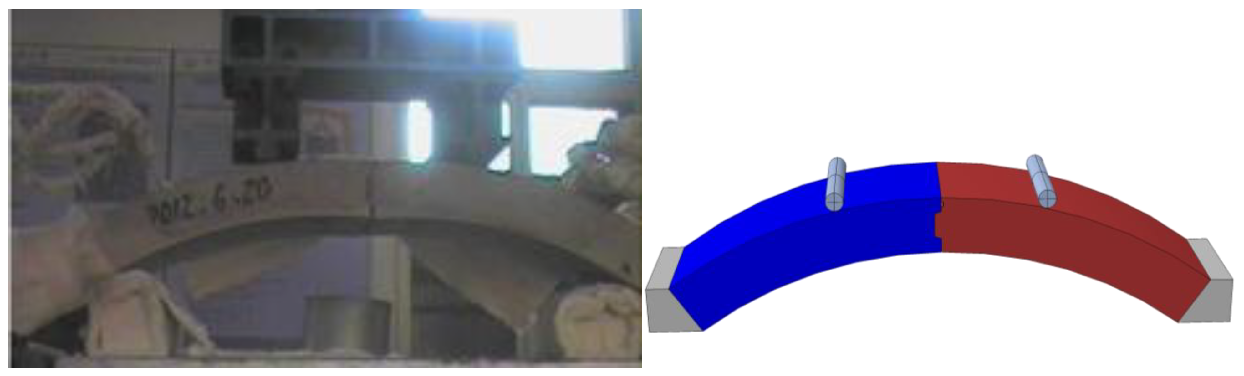
2.3. Verification of the Numerical Simulation Method

Using the modeling approach introduced in Section 2.2, the laboratory experiment of concrete lining segmental joints under elevated temperature carried out by Yan [14] was simulated and analyzed as the control group (specimens RCJ1 and RCJ3), as shown in Figure 5. By comparing temperature and deformation performance of experimental and analytical models RCJ1 and RCJ3 under fire, the rationality and reliability of the modeling process and model parameter selection are verified.

2.3.1. Verification of the Flexural Bearing Capacity of the Joints at Room Temperature

To verify the correctness of the flexural bearing capacity of the numerical simulation model at room temperature, the flexural bearing capacity at room temperature of specimen RCJ1 was compared with the simulation results. The vertical load resistance capacity measured in the test is 11.38 kN·m, and the vertical load resistance capacity measured in the numerical simulation model is 12.30 kN·m. The error between the simulation and the test value is only 8.08%, as shown in Table 4. The simulation results are generally in good agreement with the test results. Therefore, the numerical modeling method used in this study to obtain the bearing capacity of the joint at room temperature is reliable.

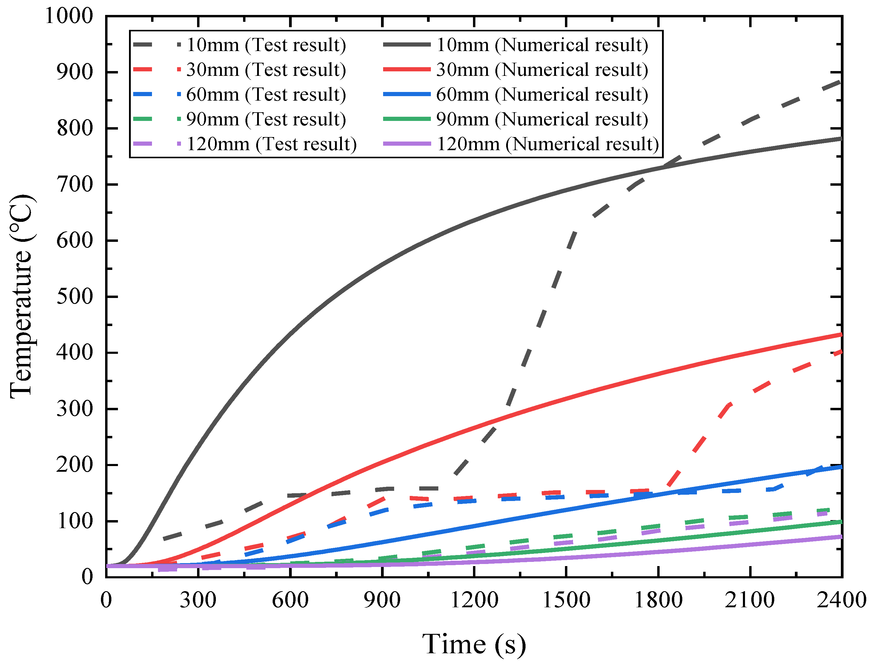
2.3.2. Verification of the Temperature Field Analysis Model

The temperature time histories of different temperature measurement points of a joint are obtained through heat transfer analysis. Figure 6 shows the numerical and experimental comparison results of the temperature time histories of the joint under fire exposure. As shown in Figure 6, the change trends of the experimental and numerical results of the temperature measuring points at different positions are basically the same. The time–temperature curve of the measuring points 10 mm and 30 mm away from the surface on fire exhibit a noticeable prolonged plateau at a temperature, but the numerical results have no such plateaus. This phenomenon could not be accurately simulated due to the evaporation of water, which removes the heat of the lining concrete. As the water in the fire area evaporates, the temperature rises rapidly, and the simulated temperature is getting closer to the measured temperature. At 2400 s, the temperature error between the numerical value and the test result is small, and each measuring point reaches the maximum temperature at this time. The maximum temperature of concrete structures under fire is a crucial factor affecting the bearing capacity. Therefore, the thermal parameters and heat transfer analysis modeling of concrete and steel in this study can reflect the effect of fire on structural performance.

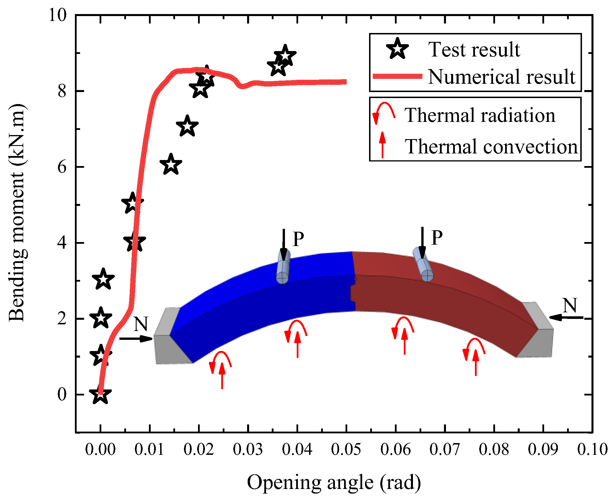
2.3.3. Verification of the Flexural Bearing Capacity of Joints under Fire

To verify the correctness of the flexural bearing capacity of the model under fire, the flexural bearing capacity test and numerical results of specimen RCJ3 under fire were compared and analyzed. Figure 7 shows the numerical and experimental comparison results of the M-θ curves of specimen RCJ3. As shown in Figure 7, the vertical load resistance capacity measured in the test is 9.04 kN·m, and the vertical load resistance capacity measured in the numerical simulation model is 8.56 kN·m. The error between the simulation and the test value is only 5.31%, as shown in Table 4. It can be seen that the test values of the bending moment and the opening angle of the segment are basically distributed around the curve of the numerical simulation results. Therefore, the numerical modeling method used in this study to obtain the bearing capacity of the joint under fire is reliable.

3. Results and Analysis

3.1. Flexural Bearing Capacity of Joints at Room Temperature

To compare the mechanical properties of the four types of joints at room temperature, an axial force of 500 kN is applied to the joints, and the displacement loading method simulates the four-point loading test. The vertical displacement value of the midpoint of the lower edge of the joint is extracted, and the flexural bearing capacity–displacement load curves are obtained, as shown in Figure 8. Figure 8 shows that the flexural bearing capacity–displacement load curves can be roughly divided into elastic stage I, elastic–plastic stage Ⅱ, and decline stage Ⅲ. In elastic stage I, the flexural bearing capacity of the BPJ is higher than that of the other three types of joints. In the elastic–plastic stage Ⅱ and softening decline stage Ⅲ, the MJ first reaches a peak load of 3176 kN, and the deformation of the joint is still small. Therefore, the mortise joint needs to cooperate with other connection methods to improve the flexural bearing capacity of the joint. By comparing the displacement corresponding to the peak load, the displacement values of the BPJ and BMJ with a bolted connection are 9 mm and 10 mm, respectively, which are significantly smaller than the 14 mm displacement value of the PJ. The bolted connection can reduce the displacement corresponding to the peak load. As far as the load peak is concerned, the peak load of the BPJ using bolted and pinned connections is significantly larger than that of the BMJ and PJ. The peak load of the joints is effectively improved under the combined action of the pin and bolts and the tongue groove.

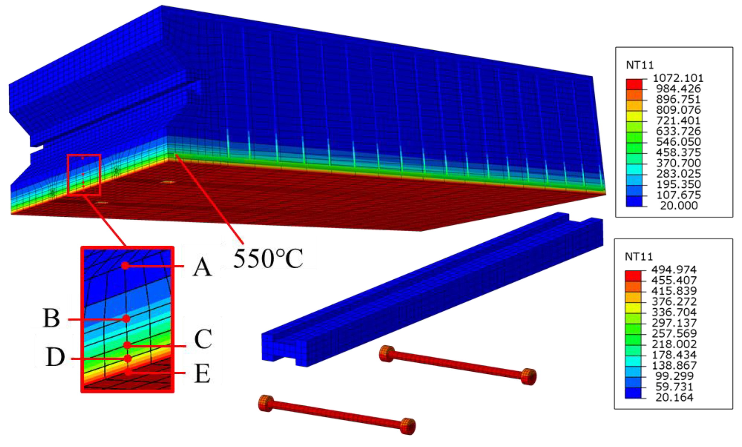
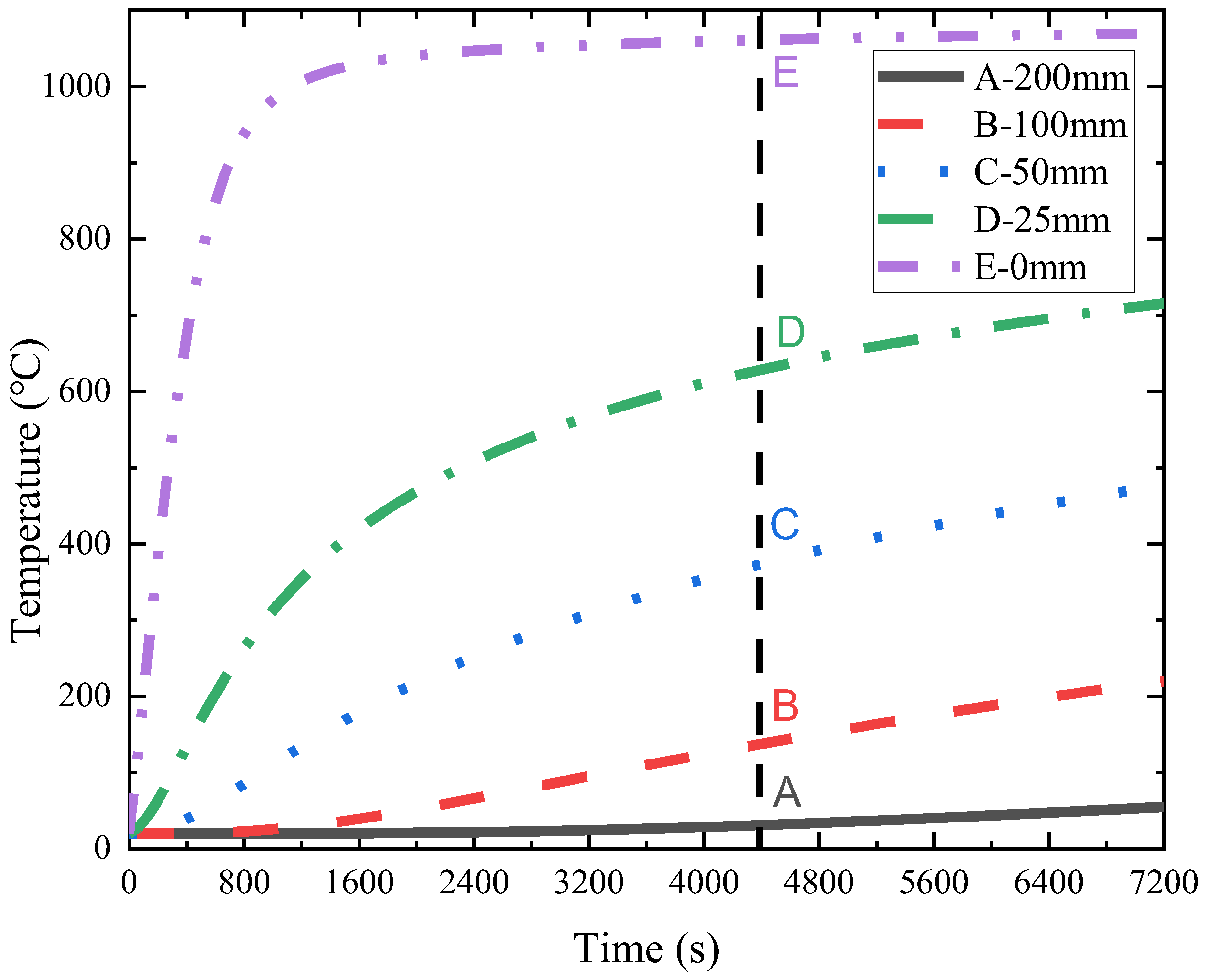
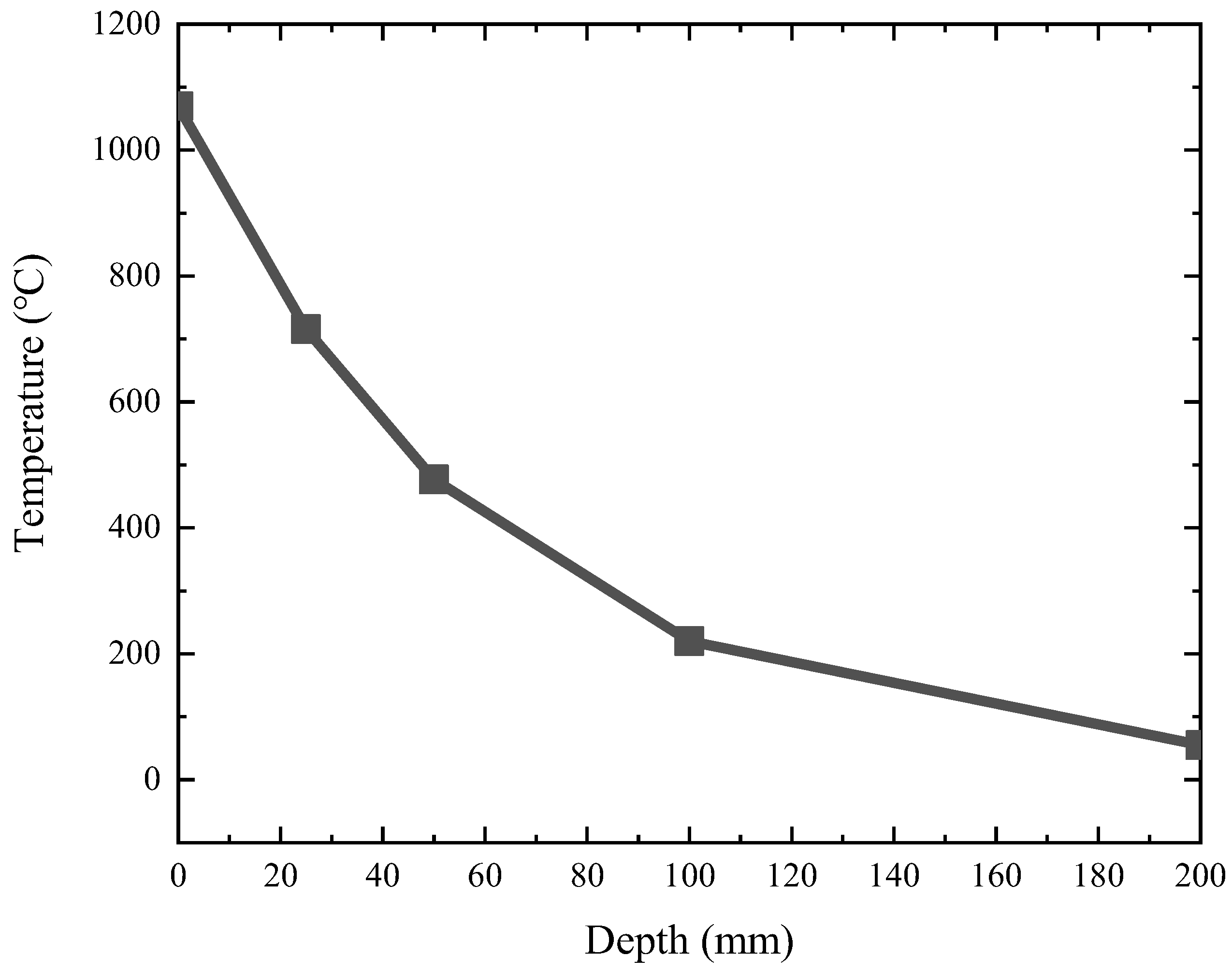
3.2. Temperature Field Analysis Model

Figure 9 shows the simulation results of the temperature field of the tunnel lining exposed to fire for 120 min. When exposed to fire for 120 min, the temperature of the inner surface of the tunnel lining reaches 1070 °C. Due to the small thermal conductivity of concrete, the outer surface of the tunnel lining is almost at room temperature during the entire fire process. Due to the good protection of the outer concrete wrapping, the temperature of the pin is kept at 20 °C, while the temperature of the bolt reaches 495 °C. From the decline rate of steel at high temperatures in Table 3, it can be seen that f p T / f y of the bolt at this time is 0.36. The temperature of the longitudinal steel bars at the tunnel joints rises rapidly, which reflects the weakness of the joints under fire, so fire prevention measures are required for the tunnel joints.
According to the direction of the lining thickness, the temperature measuring points of A~E are selected, and the distance from them to the fire receiving surface is 0~200 mm. The trend curve of the temperature at different measuring points with time is obtained, as shown in Figure 10. When exposed to fire for 120 min, at a distance of 25 mm from the inner surface of the tunnel lining, the temperature is weakened to approximately 715 °C. At a distance of 50 mm from the inner surface of the tunnel lining, the temperature is weakened to approximately 477 °C. At a distance of 100 mm from the inner surface of the tunnel lining, the temperature is weakened to approximately 220 °C, and at a position of 200 mm, the temperature is weakened to approximately 55 °C. Figure 11 shows the temperatures of different measuring points when the joint is exposed to fire for 120 min. It can be seen from the figure that the temperature on the joint decreases rapidly with increasing distance from the inner surface of the tunnel. At a depth of 0 mm to 50 mm from the inner surface of the tunnel, the rate of temperature drop is linear, while at a depth of 50 mm to 200 mm from the inner surface of the tunnel, the rate of temperature drop gradually decreases.

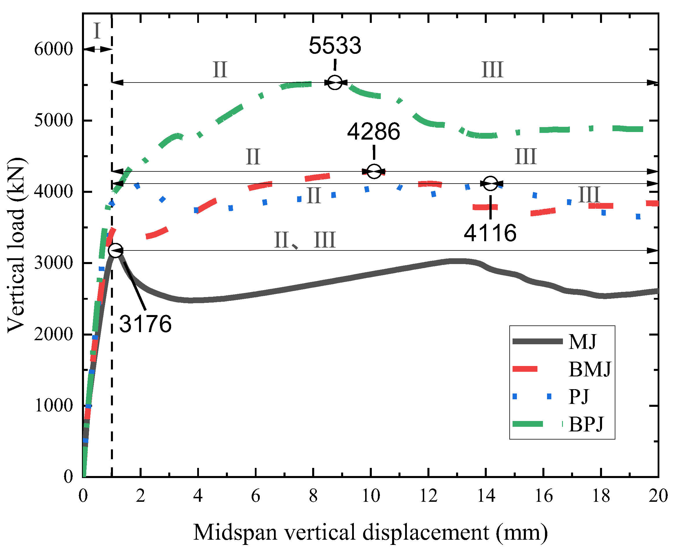
3.3. Flexural Bearing Capacity of Joints under Fire

To compare the flexural bearing capacity of the four types of joints under fire, a 500 kN axial force and the standard European HC curve of 120 min are applied to the joints to simulate a fire in a tunnel, and the displacement loading method is used to simulate the four-point loading test process of the joints under fire. The vertical displacement value of the midpoint of the lower edge of the joint is extracted, and the flexural bearing capacity–displacement load curves are obtained, as shown in Figure 12. Under the standard European HC curve of 120 min, the flexural bearing capacity–displacement load curves of the MJ and BMJ are basically the same, and the flexural bearing capacity–displacement load curves of the PJ and BPJ are basically the same. Figure 13 shows the comparison results of the flexural bearing capacity of the joints under fire and at room temperature. The degree of decrease in the flexural bearing capacity of fire is expressed by the ratio η and its expression, as detailed in Equation (4):
η = P 1 P 2
where P1 represents the flexural bearing capacity of the joint at room temperature and P2 represents the flexural bearing capacity of the joint under fire.
From Figure 13, when the fire lasts for 120 min, the ratio η reaches 18% due to the absence of connecting components in the MJ. Since the bolt temperature reaches 495 °C, the connection function has been lost after 120 min of fire, and the flexural capacity of BMJ decreases the most, and its ratio η is 16%. The ratio η of the PJ and BPJ under 120 min of fire exposure is significantly higher than that of the other two joints, 52% and 38%, respectively. Because the temperature of the pin does not increase significantly after 120 min of fire, the connection of the pin still has a certain connection function. The decrease degree of the vertical peak load of the MJ and BMJ is greater than that of the PJ and BPJ joints. It can be seen that the results of the ratio η of the four joints correspond to the results of the temperature field analysis.

3.4. Opening

Structural deformation is the primary reference for judging the limited state of a structure. In this study, the opening outside of the joint is used as the index to judge structural deformation. To compare the deformation characteristics of the four types of joints under fire, a 500 kN axial force and the standard European HC curve of 120 min are applied to the joint. The opening of the upper edge of the joint is extracted, and the relationship curve of the opening with time is obtained, as shown in Figure 14. Figure 14 shows that the openings of the four types of joints increase rapidly from 0 to 10 min and then slowly increase. Among them, the MJ and BMJ have basically the same variation in the opening from 0 to 5 min, and the change rate of the opening is greater than that of the other two joints. Under a fire of 120 min, the openings of the MJ, BMJ, PJ, and BPJ are 46 mm, 37 mm, 30 mm, and 19 mm, respectively. During the 120 min fire, the opening of the BPJ is much smaller than that of the other three joints. The combined action of the pin and bolts and tongue groove can effectively reduce the opening of the joint.

3.5. Influence of Axial Force

To explore the influence of the initial axial force on the flexural bearing capacity and opening of the four types of joints under fire, the joints with the standard European HC curve of 120 min under the two working conditions of 500 kN and 1000 kN initial axial forces are compared. The flexural bearing capacity–displacement load curves and the opening curve of the 120 min fire under different initial axial forces are shown in Figure 15 and Figure 16, respectively.
Figure 15 shows that the initial axial force changed from 500 kN to 1000 kN, the vertical peak load of the MJ changed from 565 kN to 642 kN, the vertical peak load of the BMJ changed from 703 kN to 581 kN, and the flexural bearing capacity–displacement load curves of the MJ and BMJ did not change much. The vertical peak loads of the PJ and BPJ increased from 2150 kN to 2410 kN and 2105 kN to 2433 kN, respectively. It can be seen that increasing the initial axial force is beneficial for improving the flexural bearing capacity of the PJ and BPJ under fire. However, it does not significantly improve the flexural bearing capacity of the PJ and BPJ.
Figure 16 shows that the size of the initial axial force will significantly impact the opening of the joint. When the initial axial force is changed from 500 kN to 1000 kN, after 120 min of fire, the opening of the MJ is reduced from 46 mm to 28 mm, the opening of the BMJ is reduced from 37 mm to 17 mm, the opening of the PJ is reduced from 30 mm to 13 mm, and the opening of the BPJ is reduced from 19 mm to 4 mm. The openings of the four joints are reduced after increasing the initial axial force.

4. Conclusions

This research used the finite element calculation software ABAQUS to analyze the mechanical behavior and temperature field distribution of different types of fabricated frame tunnel joints (mortise joints, bolt-mortise joints, pin joints, and bolt-pin joints) under fire and at room temperature and studied the influence of the initial axial force on the flexural bearing capacity and the opening of the joints under fire. The following conclusions were obtained:
(1)
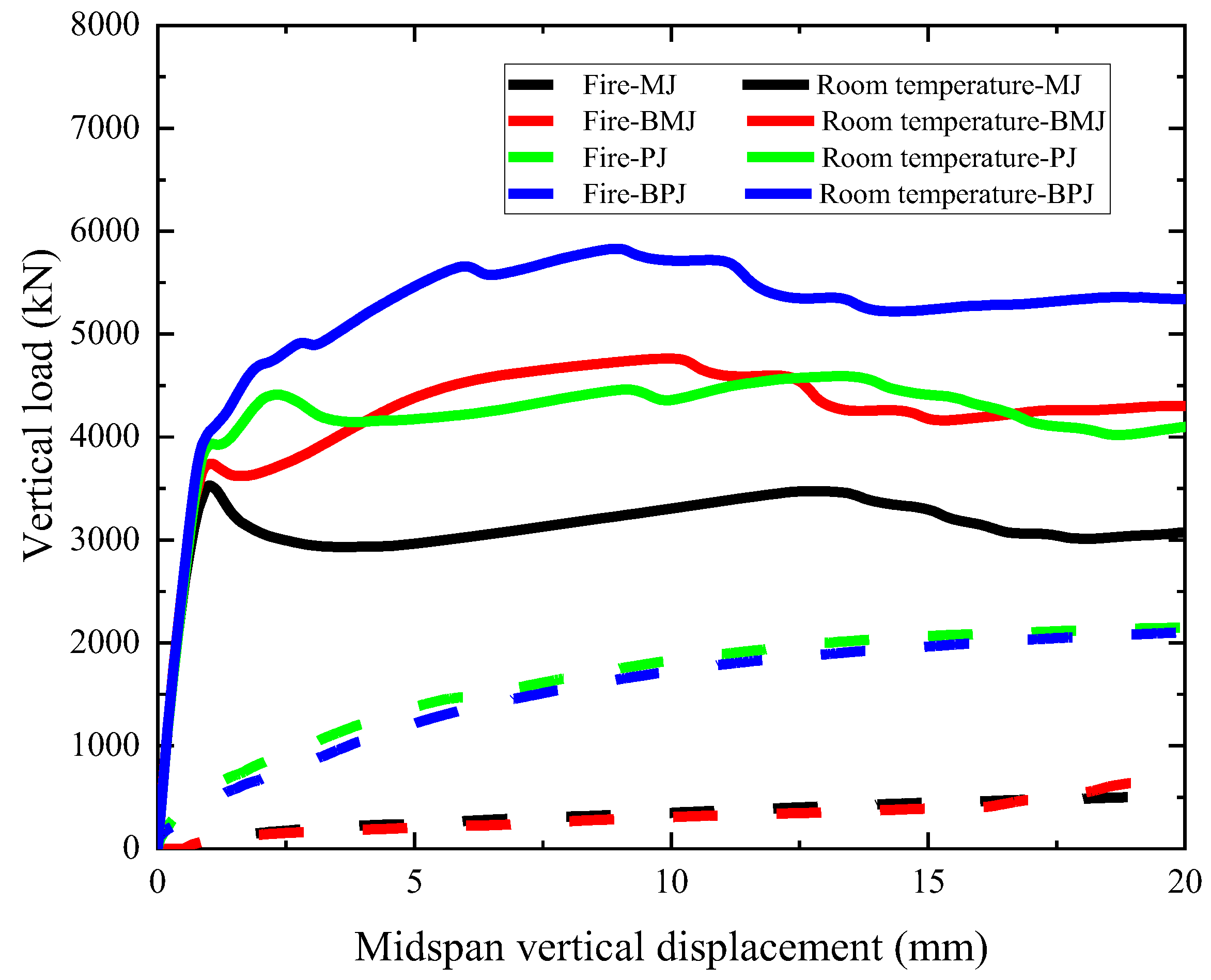
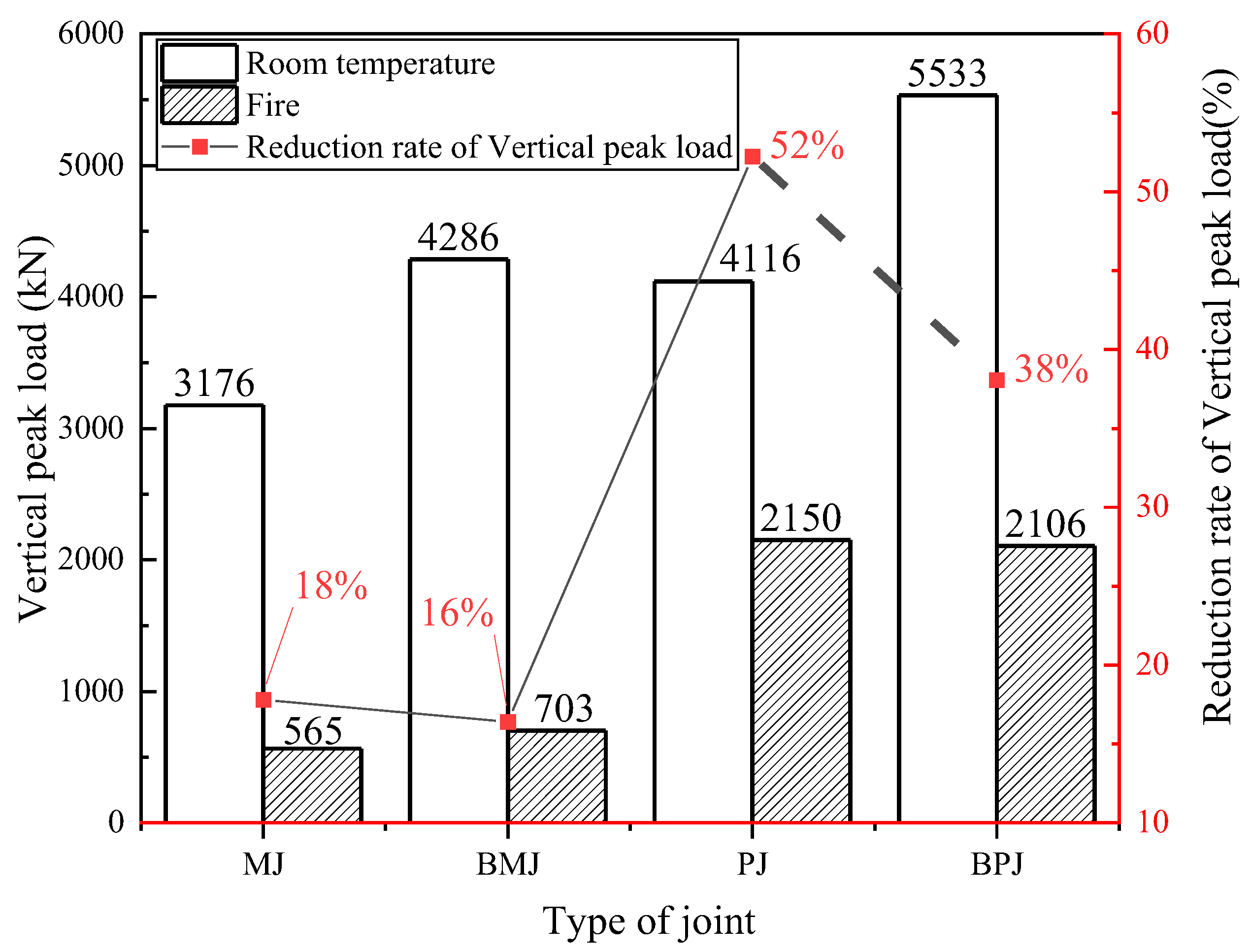
The vertical peak load of the BPJ is higher than that of the other three joints at room temperature, and the combined action of the pin and bolts and the tongue groove can effectively increase the vertical peak load of joints and reduce the midspan vertical displacement.
(2)
Under a fire of 120 min, the bolts of BPJ reach 495 °C, while the temperature of the pin is kept at 20 °C. The external concrete can prevent the pin from overheating.
(3)
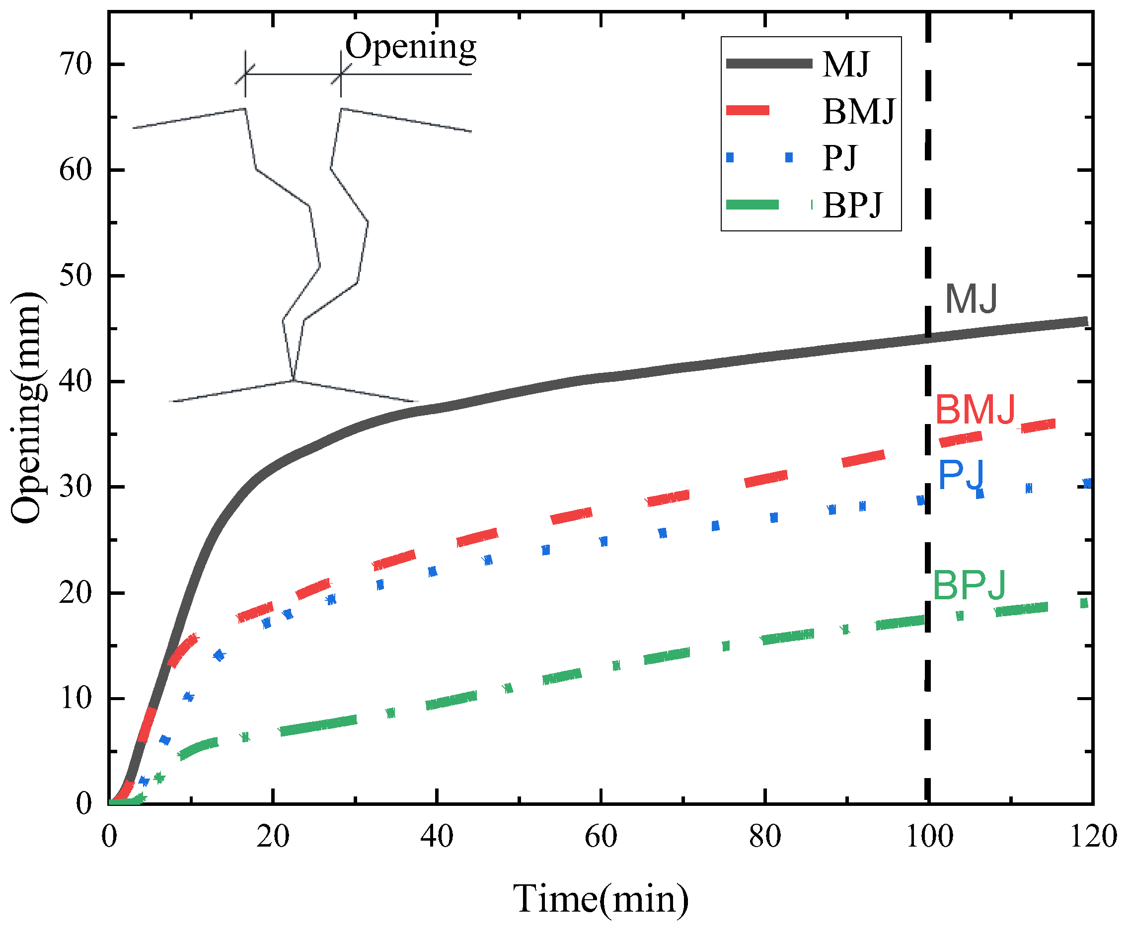
The load–displacement curves of the MJ and BMJ under fire are basically the same, the load–displacement curves of the PJ and BPJ are basically the same, the decrease degree of the vertical peak load of the MJ and BMJ is greater than that of the PJ and BPJ joints, and the opening of the BPJ is much smaller than that of the other three types of fabricated frame tunnel joints.
(4)
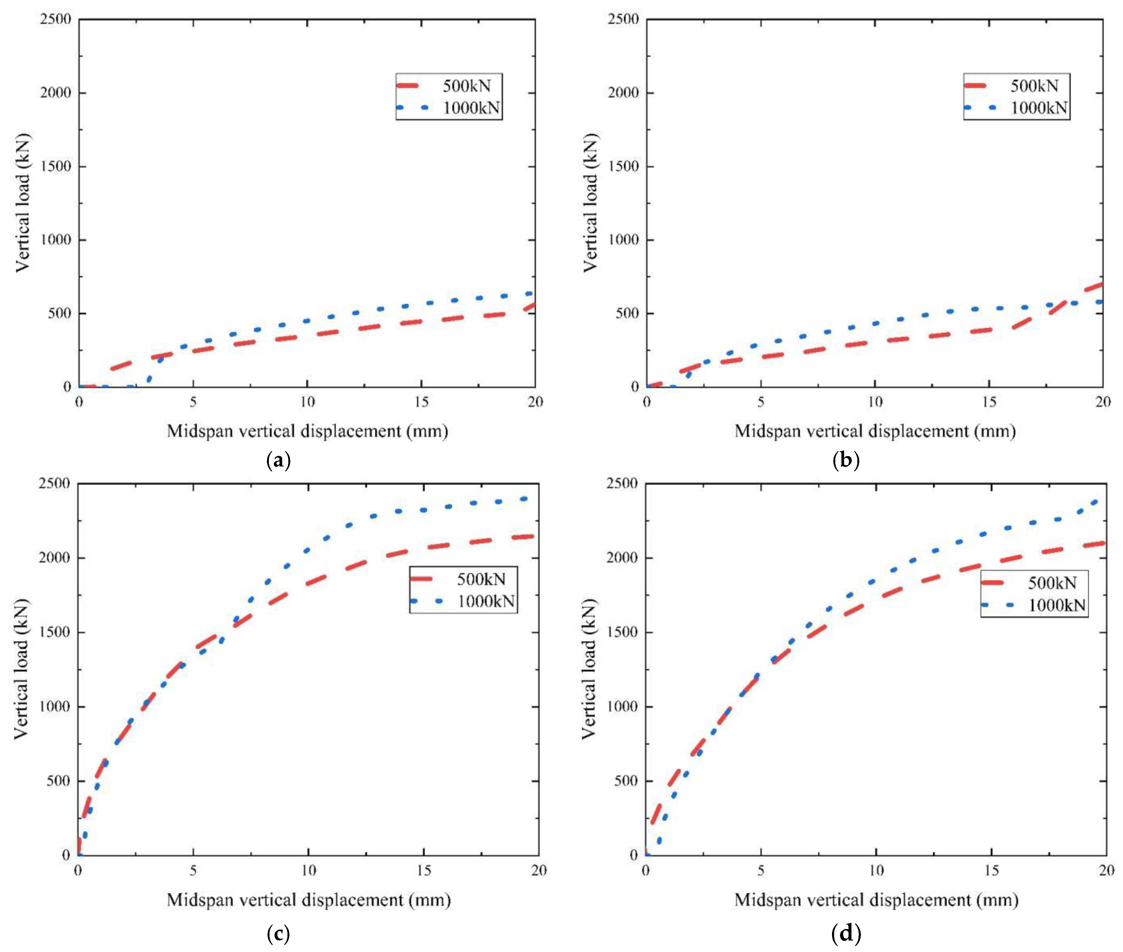
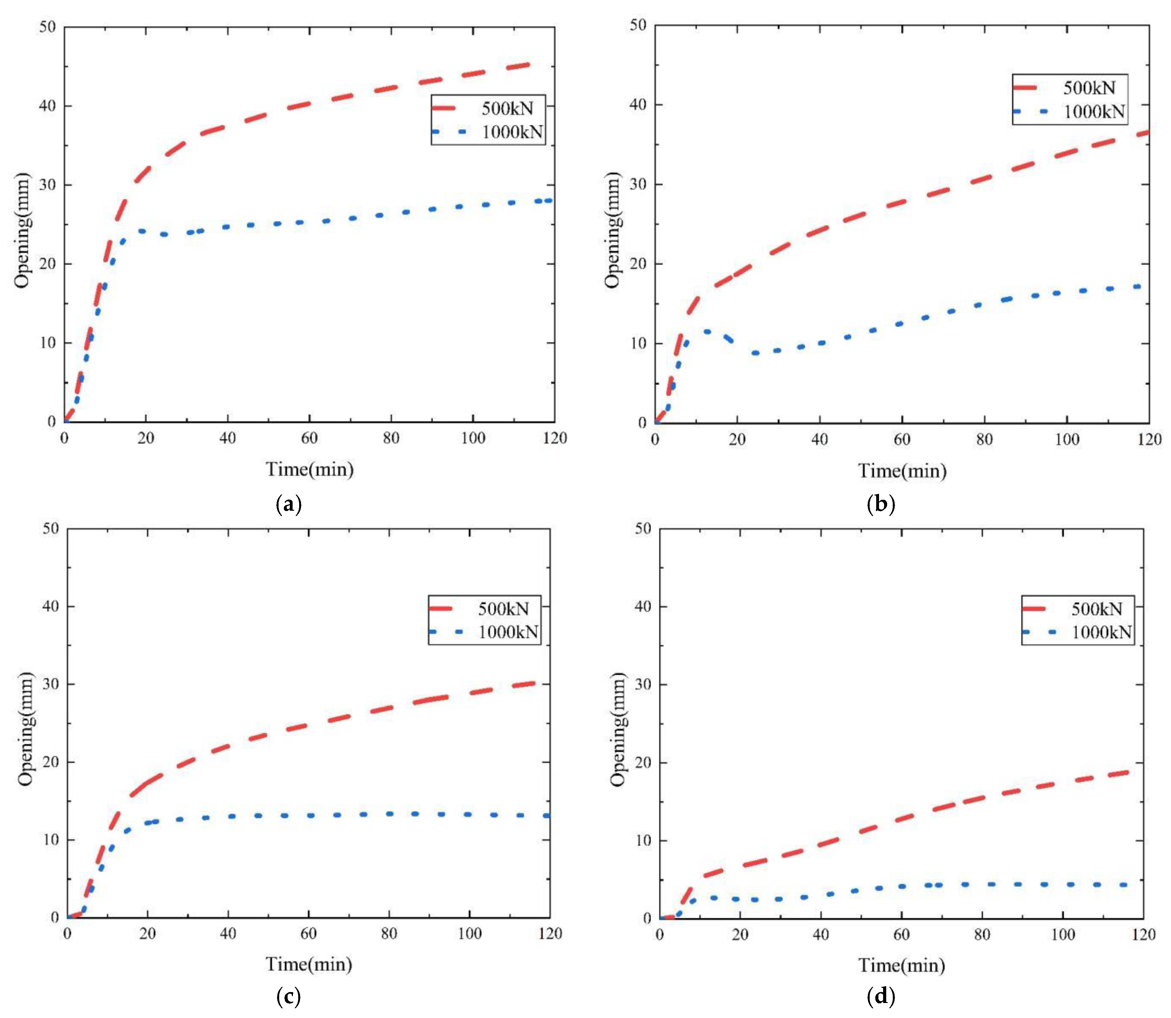
When the initial axial force is increased, the openings of the four joints under fire are reduced, and the vertical peak loads of PJ and BPJ are increased, while the vertical peak loads of MJ and BMJ are not significantly increased.

Author Contributions

Conceptualization, Z.H.; methodology, Z.H. and J.Z.; software, J.Z.; validation, J.Z.; formal analysis, Z.H.; investigation, J.Z., Z.P., H.H., H.A., X.Y. and T.X.; data curation, J.Z.; writing—original draft preparation, J.Z.; writing—review and editing, Z.H. and T.X.; visualization, J.Z.; supervision, Z.H.; project administration, Z.H., Z.P. and H.H.; funding acquisition, Z.H. and Z.P. All authors have read and agreed to the published version of the manuscript.

Funding

This work is supported by the National Natural Science Foundation of China (No. 52208388), the Guangxi science and technology base and talent special project (No. AD21220039), and the Science and Technology Progress and Innovation Plan Project of the Department of Transportation of Hunan Province (No. 202147).

Institutional Review Board Statement

Not applicable.

Informed Consent Statement

Not applicable.

Data Availability Statement

Some or all data, models, or code that support the findings of this study are available from the corresponding author upon reasonable request.

Conflicts of Interest

The author(s) declare that there is no potential conflict of interest with respect to the research, authorship, and/or publication of this article.

References

  1. Kirkland, C.J. The fire in the Channel Tunnel. Tunn. Undergr. Space Technol. Inc. Trenchless Technol. Res. 2002, 17, 129–132. [Google Scholar] [CrossRef]
  2. Dorgarten, H.W.; Balthaus, H.; Dahl, J.; Billig, B. Fire resistant tunnel construction: Results of fire behaviour tests and criteria of application. Tunn. Undergr. Space Technol. 2004, 19, 314. [Google Scholar] [CrossRef]
  3. Lai, H.P.; Wang, S.Y.; Xie, Y.L. Experimental research on temperature field and structure performance under different lining water contents in road tunnel fire. Tunn. Undergr. Space Technol. Inc. Trenchless Technol. Res. 2014, 43, 327–335. [Google Scholar] [CrossRef]
  4. Zhang, Y.; Zeiml, M.; Maier, M.; Yuan, Y. Lackner Roman Fast assessing spalling risk of tunnel linings under RABT fire: From a coupled thermo-hydro-chemo-mechanical model towards an estimation method. Eng. Struct. 2017, 142, 1–19. [Google Scholar] [CrossRef]
  5. Rui, R.; Hui, Z.; Zhao, H.; He, S.; Wang, X. Statistical analysis of fire accidents in Chinese highway tunnels 2000–2016. Tunn. Undergr. Space Technol. 2019, 83, 452–460. [Google Scholar] [CrossRef]
  6. Huang, Z.; Zhang, C.L.; Ma, S.K.; Zhang, J.B.; Zhu, Q.X. Study of the mechanical behaviour and damage characteristics of three new types of joints for fabricated rectangular tunnels using a numerical approach. Tunn. Undergr. Space Technol. 2021, 118, 104184. [Google Scholar] [CrossRef]
  7. Huang, Z.; Zhang, C.L.; Ma, S.K.; Zhang, H.; Zhou, Z.; Li, H.Z. Parameter Sensitivity Analysis of a New Fabricated Rectangular Tunnel Joint Using Numerical Method. KSCE J. Civ. Eng. 2021, 26, 907–920. [Google Scholar] [CrossRef]
  8. Huang, Z.; Bai, H.W.; Ma, S.K.; Zhang, J.W.; Chen, Y.M.; Li, H.Z. Large-scale testing of the mortise and tenon joint performance of the tunnel lining of prefabricated frame tunnels. Tunn. Undergr. Space Technol. 2023, 131, 104828. [Google Scholar] [CrossRef]
  9. Lin, J.; Dong, Y.; Duan, J.; Zhang, D.; Zheng, W. Experiment on single-tunnel fire in concrete immersed tunnels. Tunn. Undergr. Space Technol. 2021, 116, 104059. [Google Scholar] [CrossRef]
  10. Duan, J.; Dong, Y.; Xiao, J.; Zhang, D.; Zheng, W.; Zhang, S. A large-scale fire test of an immersed tunnel under the protection of fire resistive coating. Tunn. Undergr. Space Technol. 2021, 111, 103844. [Google Scholar] [CrossRef]
  11. Guo, J.; Jiang, S.; Zhang, Z. Fire Thermal Stress and its Damage to Subsea Immersed Tunnel. Procedia Eng. 2016, 166, 296–306. [Google Scholar] [CrossRef]
  12. Yan, Z.G.; Zhu, H.H.; Ju, J.W.; Ding, W.Q. Full-scale fire tests of RC metro shield TBM tunnel linings. Constr. Build. Mater. 2012, 36, 484–494. [Google Scholar] [CrossRef]
  13. Yan, Z.G.; Zhu, H.H.; Ju, J.W. Behavior of reinforced concrete and steel fiber reinforced concrete shield TBM tunnel linings exposed to high temperatures. Constr. Build. Mater. 2013, 38, 610–618. [Google Scholar] [CrossRef]
  14. Yan, Z.; Shen, Y.; Zhu, H.; Lu, Y. Experimental study of tunnel segmental joints subjected to elevated temperature. Tunn. Undergr. Space Technol. 2016, 53, 46–60. [Google Scholar] [CrossRef] [Green Version]
  15. Ye, J.; Li, J. Fire Experiments of Shield Tunnel Segments and Joints. China J. Highw. Transp. 2022, in press. [Google Scholar]
  16. Guo, Z.; Song, J.; Liu, Y.; Wang, X.; Liu, Y.; Ma, C.; Li, F. Experimental study on mechanical behavior of splicing joints of shield tunnel lining subjected to fire. China Civ. Eng. J. 2022, 55, 94–104. [Google Scholar] [CrossRef]
  17. Yin, Y.; Guo, Z.; Song, J.; Liu Yi Wang, X.; Liu, Y.; Li, F. Mechanical behaviour of splicing joints in shield tunnel lining subjected to fire. Tunn. Undergr. Space Technol. 2022, 123, 104404. [Google Scholar] [CrossRef]
  18. Zhang, W.; Zhang, X.; Song, X. Mechanical properties of shield tunnel with inclined bolt joint and temperature distribution law under fire. J. Traffic Transp. Eng. 2018, 18, 37–49. [Google Scholar] [CrossRef]
  19. Hua, N.; Tessari, A.; Khorasani, N.E. The effect of geologic conditions on the fire behavior of tunnels considering soil-structure interaction. Tunn. Undergr. Space Technol. 2022, 122, 104380. [Google Scholar] [CrossRef]
  20. Zhang, Q.; Zhou, C.; Sun, C.; Li, H.; Guo, Z. Study on the Pattern of Temperature Propagation of Reinforced Concrete Structure under High-Temperature Environment. Mod. Tunn. Technol. 2021, 58, 185–193. [Google Scholar] [CrossRef]
  21. Ding, R.; Fan, S.; Wu, M. Numerical study on fire resistance of rectangular section stainless steel-concrete composite beam. Fire Saf. J. 2021, 125, 103436. [Google Scholar] [CrossRef]
  22. Zhang, G.; Zhang, W.; Yu, G.; Lel, J. Model Test on Thermomechanical Coupling of Shield Tunnel Lining Under High Fire Temperature. China J. Highw. Transp. 2019, 32, 120–128. [Google Scholar] [CrossRef]
  23. Saleheen, Z.; Krishnamoorthy, R.R.; Nadjai, A. A review on behavior, material properties and finite element simulation of concrete tunnel linings under fire. Tunn. Undergr. Space Technol. 2022, 126, 104534. [Google Scholar] [CrossRef]
  24. Eurocode 3; Eurocode 3: Design of Steel Structures—Part 1–2: General Rules—Structural Fire Design. European Committee for Standardization (CEN): Brussels, Belgium, 2005.
  25. Eurocode 4; Eurocode 4: Design of Composite Steel and Concrete Structures—Part 1–2: General Rules—Structural Fire Design. European Committee for Standardization (CEN): Brussels, Belgium, 2005.
  26. Guo, Z.; Li, W. Experimental investigation of strength and deformation of concrete at elevated temperature. J. Build. Struct. 1993, 14, 8–16. [Google Scholar]
Figure 1. Fabricated frame tunnel joints.
Fire 06 00003 g001
Figure 2. Geometry of the BPJ (dimensions in mm).
Fire 06 00003 g002
Figure 3. Model mesh (dimensions in mm).
Fire 06 00003 g003
Figure 4. Loading methods.
Fire 06 00003 g004
Figure 5. Comparison of the analytical model and experiments [14].
Fire 06 00003 g005
Figure 6. Comparison of the temperature field of specimen RCJ3.
Fire 06 00003 g006
Figure 7. Comparison between the M-θ curves of specimen RCJ3 and the analytical model.
Fire 06 00003 g007
Figure 8. Load–displacement curves of the four joints at room temperature.
Fire 06 00003 g008
Figure 9. Cross-section temperature distributions after two hours of heating.
Fire 06 00003 g009
Figure 10. Temperature–time curves of concrete of various components of the model.
Fire 06 00003 g010
Figure 11. Temperature–thickness curves of concrete at measuring points after two hours of heating.
Fire 06 00003 g011
Figure 12. Load–displacement curves of four joints under fire exposure and at room temperature.
Fire 06 00003 g012
Figure 13. Flexural bearing capacity of four joints under a fire of 120 min and at room temperature.
Fire 06 00003 g013
Figure 14. The opening gap fire time of the four joints.
Fire 06 00003 g014
Figure 15. Load–displacement curves of the four joints with different initial axial forces. (a) MJ. (b) BMJ. (c) PJ. (d) BPJ.
Fire 06 00003 g015
Figure 16. The opening gap fire time of the four joints with different initial axial forces. (a) MJ. (b) BMJ. (c) PJ. (d) BPJ.
Fire 06 00003 g016
Table 1. Material properties of C60 concrete at room temperature.
Density
(kg/m3)
The Axial Compressive Strength of Concrete
(N/mm2)
Elasticity Modulus
(N/mm2)
Poisson Ratio
240040.235,992.80.2
Table 2. Material properties of steel at room temperature.
TypeElasticity Modulus
(MPa)
Yield Stress (MPa)Yield StrainUltimate StrainPoisson Ratio
Steel bar2 × 10−115000.020.150.28
H-pin
C-slot
2 × 10−113350.020.20.28
Bolt2 × 10−119000.020.20.28
Table 3. The decline rate of steel at high temperature.
Temperature/°C20100200300400500600700800900
E s T / E s 110.90.80.70.60.310.130.090.0675
f y T / f y 111110.780.470.230.110.06
f P T / f P 110.8070.6130.420.360.180.0750.050.0375
Table 4. Comparison between numerical simulation and experimental results of the tunnel segmental joint.
No.Fire LoadMid-Span Ultimate Bending Moment (kN·m) Error   =   M A M B M A × 100 %
MAMB
RCJ1-11.3812.308.08%
RCJ3HC9.048.565.31%
Note: in the table, MA is the experimental result of ultimate bearing capacity of the joint and MB is the numerical simulation result of ultimate bearing capacity of the joint.
Disclaimer/Publisher’s Note: The statements, opinions and data contained in all publications are solely those of the individual author(s) and contributor(s) and not of MDPI and/or the editor(s). MDPI and/or the editor(s) disclaim responsibility for any injury to people or property resulting from any ideas, methods, instructions or products referred to in the content.

