1. Introduction
The use of bricks in construction has a long history dating back to ancient civilizations [
1]. Over time, the manufacturing process of bricks has evolved, leading to the development of new and improved materials. In recent years, Computational Fluid Dynamics (CFD) software has become an invaluable tool for studying the thermal behavior of materials, including bricks. This has opened up new avenues for research and development in the field of construction materials.
The thermal insulation properties of a building wall can be affected by the type of bricks used in its construction. Bricks can vary in their thermal conductivity, which is a measure of how easily heat flows through the material [
2]. For example, solid bricks made of dense materials like concrete or clay have a higher thermal conductivity than hollow bricks made of lightweight materials like clay, cement, or pumice. This means that solid bricks will transfer more heat through the wall, resulting in higher energy costs for heating and cooling the building.
On the other hand, hollow bricks with air pockets inside provide a layer of insulation and can reduce heat transfer through the wall. The air pockets act as a barrier to the transfer of heat, which can help to keep the building cooler in the summer and warmer in the winter [
3].
Clay bricks have a relatively low thermal conductivity due to the low thermal coefficient of clay, which means they are good insulators. However, the thermal conductivity of a clay brick can be further reduced by incorporating insulating materials such as perlite or vermiculite into the clay mixture during production. These materials create air pockets within the brick, which provide additional insulation and reduce heat transfer through the wall [
4].
In addition to the type of bricks used, the thickness and composition of the mortar between the bricks can also affect the thermal insulation properties of the wall. If the mortar is too thin or does not bond well with the bricks, it can create gaps that allow heat to escape or enter the building. Choosing the right type of brick and mortar for a building wall can have a significant impact on its thermal insulation properties and, ultimately, on the energy efficiency and comfort of the building [
5].
Plaster can also play an important role in the thermal insulation of buildings. When applied properly, plaster can help to improve the thermal performance of a wall by reducing heat transfer through the wall. One of the main ways that plaster can improve thermal insulation is by filling in gaps and imperfections in the wall surface. These gaps and imperfections can create areas where heat can escape or enter the building. By applying a layer of plaster over the wall surface, these gaps and imperfections can be filled, creating a more uniform surface that reduces heat transfer [
6].
In this article, the thermal behavior of a traditional Greek brick and a new different type of brick will be compared using CFD software. Specifically, (i) the geometry of the bricks and (ii) the impact of the thermal coefficient of fired material on the thermal behavior of the bricks will be explored. This parameter, which varies depending on the manufacturing process, has a significant influence on the heat transfer properties of the bricks, which in turn affects their thermal performance in construction applications.
The primary objective of this study was to examine the effect of the thermal coefficient on fired materials by constructing and analyzing two different clay mixtures. The first mixture comprised argile clay material, while the second and third mixtures incorporated 2% and 8% of solid waste material, specifically paper sludge [
7], respectively. The mixtures were prepared through extrusion, followed by drying and firing under laboratory conditions that simulated real brick industry production environments. Data on the density and thermal coefficient of the fired samples were collected and analyzed to evaluate their overall properties and understand the impact of geometric variations and waste additive inclusion on thermal insulation characteristics. This investigation aimed to provide valuable insights into optimizing the thermal insulation efficiency of bricks and their applications in building construction.
To achieve this objective, various geometric parameters were systematically altered, and the corresponding thermal insulation properties were measured. The study focused on understanding how changes in the brick’s geometry, such as dimensions, shape, and surface patterns, affected its ability to prevent heat transfer [
8]. Additionally, the research examined the effects of incorporating a waste additive into the brick manufacturing process, which resulted in a reduction in the final product’s density [
9]. The investigation aimed to determine the extent to which this density reduction influenced the thermal insulation properties of the bricks and the walls constructed using them.
By analyzing these critical factors, the study sought to provide valuable insights into optimizing the thermal insulation efficiency of bricks and their applications in building construction.
Table 1.
The three (3) labeled constructed mixtures with the ratio of the additive in the mixture.
Table 1.
The three (3) labeled constructed mixtures with the ratio of the additive in the mixture.
| Mixture | TZ | TPS2 | TPS8 |
|---|
| | wt.% | wt.% | wt.% |
|---|
| Clay material TZ | 100 | 98 | 92 |
| Paper sludge | - | 2 | 8 |
The aforementioned data (
Table 1) on the thermal coefficient of the fired clay mixtures were utilized in the computational fluid dynamics (CFD) simulations to analyze the thermal performance of two actual bricks. The objective was to investigate the impact of the density and thermal coefficient of the clay on the thermal behavior of the bricks and their influence on the building’s overall thermal performance.
By analyzing the thermal behavior of current perforated bricks and new types of bricks (vertical perforated clay blocks), insights can be gained into the advantages and disadvantages of each material, as well as identify areas for further research and development. Ultimately, this research has the potential to inform the selection of bricks for construction projects, leading to more efficient and sustainable building practices.
Traditionally, research in the field has predominantly focused on two distinct areas: the impact of brick geometry on the thermal behavior of buildings and the influence of waste additives on the physicochemical properties of fired bricks [
10]. However, this study aims to bridge these two sectors of investigation by examining the combined effects of brick geometry and waste additives on thermal performance. By integrating these two previously separate areas of study, the research intends to provide a comprehensive understanding of how both factors interact and contribute to the overall thermal behavior and insulation properties of the bricks. This novel approach seeks to offer valuable insights into optimizing the design and production of bricks with enhanced thermal insulation capabilities, thereby advancing sustainable building practices.
2. Materials and Methods
2.1. Brick Products
Hollow bricks with horizontal holes are a type of clay brick that have one or more rows of continuous, horizontal holes running through the brick. These holes are typically located in the center of the brick and run parallel to the ground. This type of brick is the most common in the Greek market [
11].
The purpose of the horizontal holes is to reduce the weight of the brick and provide better insulation. By creating hollow spaces within the brick, it becomes lighter and easier to handle during construction [
12]. Additionally, the hollow spaces create a barrier that helps to prevent heat transfer, keeping the interior of a building cooler in the summer and warmer in the winter.
Hollow bricks with horizontal holes are commonly used in construction for both load-bearing and non-load-bearing walls. They are available in a variety of sizes and shapes, including standard rectangular bricks, corner bricks, and bricks with interlocking edges. Bricks can be used in a variety of applications, including residential, commercial, and industrial construction.
For the current study, the drawing of the most common constructing brick in the Greek market was provided by the company SABO S.A. for the purpose of the tests. The dimensions of the brick are 120 × 90 × 190 mm (Height × Width × Length) and can be seen in
Figure 1.
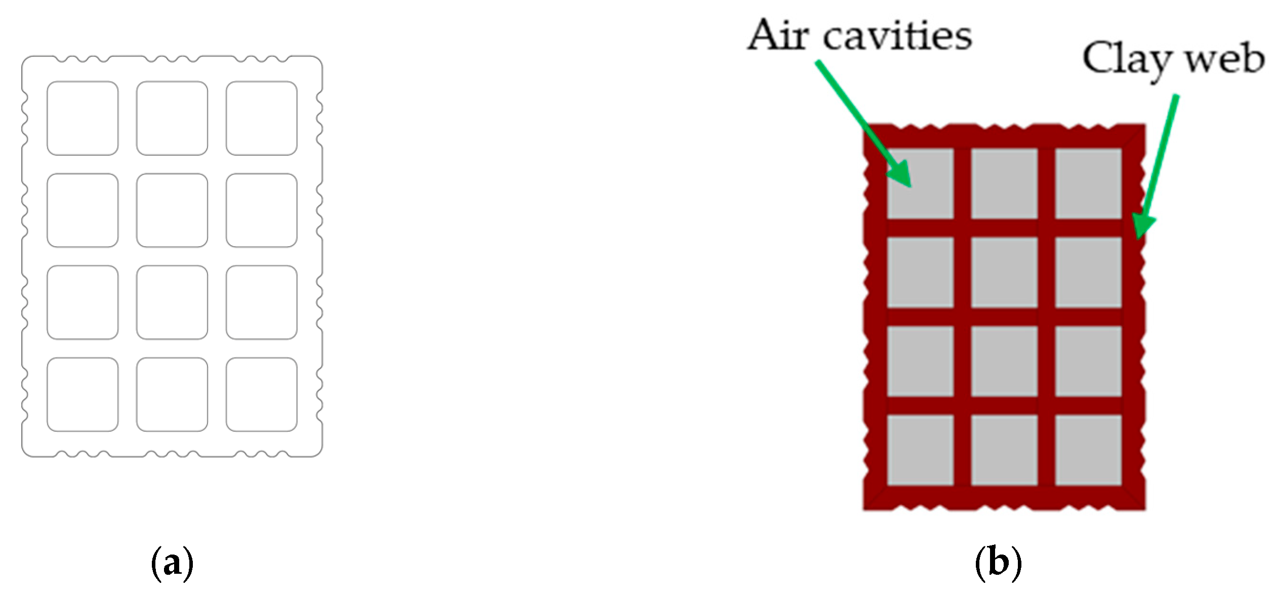
Vertically perforated bricks are a type of clay brick that have one or more vertical perforations running through the center of the brick. These perforations are typically circular or rectangular in shape and run from top to bottom rather than horizontally, like the holes in hollow bricks with horizontal holes [
13].
The vertical perforations in the bricks create a larger surface area, which allows for more air circulation and, therefore, better insulation. As mentioned earlier, hot air rises and cold air sinks, so the vertical perforations allow for natural convection currents to be established within the walls. This helps to keep the interior of the building cooler in the summer and warmer in the winter [
14].
Vertically perforated bricks are available in a variety of sizes and shapes, including standard rectangular bricks, corner bricks, and bricks with interlocking edges. They can be used in a variety of applications, including load-bearing and non-load-bearing walls, as well as for decorative purposes.
For the purpose of the study, a drawing of a new entry vertical clay block in the Greek market was provided by the SABO S.A. company. The dimensions of the brick were 240 × 250 × 250 mm (Height × Width × Length) and can be seen in the following
Figure 2.
2.2. Construction Mixture Components
2.2.1. Characteristics of Clay Material
The study utilized a typical type of clay commonly used in industrial brick production in the Evia region, which is referred to as TZ clay. According to ISO 14688-2:2017, TZ clay is an inorganic type with moderate plasticity, as its liquid limit falls within the range of 35–50%.
Table 2 provides information on the properties of the clay. The chemical composition of the clay was determined through Atomic Absorption Spectrometry (AAS), following the ISO 26845:2016 standard, and is presented in
Table 3.
The particle size of the clay was analyzed in accordance with ASTM D422-63 (2007), revealing a particle size range from 2 mm to 2 μm (
Table 4). The clay was transported from the manufacturing site to the laboratory with an average humidity content of 8.15%, and its density was measured as 1781 Kg/m
3 on average, following the ASTM D698-12 standard.
Table 2.
Physical properties of TZ clay.
Table 2.
Physical properties of TZ clay.
| Physical Properties | Unit | Values |
|---|
| Plastic limit | % | 20.76 |
| Liquid limit | % | 42.00 |
| Plasticity | % | 24.23 |
| Density | kg/m3 | 1781 |
Table 3.
Oxide composition of TZ clay.
Table 3.
Oxide composition of TZ clay.
| Oxides (%) | SiO2 | Al2O3 | CaO | Fe2O3 | MgO | K2O | Na2O | LOI |
|---|
| TZ clay | 56.45 | 16.72 | 5.65 | 5.08 | 2.73 | 1.64 | 0.55 | 9.34 |
Table 4.
Particle size distribution of clay TZ.
Table 4.
Particle size distribution of clay TZ.
| Grain Size | Coarse Sand | Fine Sand | Silt | Clay |
|---|
| >63 μm | 63–20 μm | 20 to 2 μm | <2 μm |
|---|
| TZ clay | 6.00% | 9.35% | 40.37% | 44.28% |
2.2.2. Characteristics of Solid Waste Additive
The selected additive for solid waste to decrease its final density is paper sludge. Paper sludge is a byproduct of the paper-making process, and it is considered an industrial waste. It consists of various materials such as cellulose fibers, inorganic fillers, and additives used in the paper-making process [
15].
In the past, paper sludge was often disposed of in landfills, which posed environmental problems, such as soil contamination and methane gas emissions. However, in recent years, there has been a growing interest in finding alternative uses for paper sludge to reduce waste and promote sustainability. One possible use for paper sludge is as a fuel source. It can be burned to generate energy, either alone or in combination with other fuels. Another option is to use paper sludge as a raw material in the production of other products such as bricks, cement, and fertilizer [
16].
In addition, some researchers have investigated the potential use of paper sludge as a soil amendment due to its high organic content. However, there are concerns about potential contaminants in paper sludge, such as heavy metals, which may limit its use in this way [
17].
Overall, while paper sludge is still considered an industrial waste, the use of this material can provide significant results on a brick mass. The addition of 8% paper sludge in a ceramic mass led to a decreased index of body density by 13.4%, and as a result of this fact, the thermal insulation coefficient was reduced by 17.3% [
18].
Considering these outcomes, paper sludge was selected as one of the lightweight additives to be compared with other alternatives in the current research. The paper sludge used in this study was obtained from an Israeli brick and tile factory in the Beer Sheva region and had a humidity level of 65%. Determining the grain size accurately was challenging due to the high water [
19] content in its mass. Therefore, the sludge was mixed thoroughly with the clay material TZ, which had a humidity level of 8.15%. As a result, the necessary mixing water was added to the paper sludge to achieve a homogenous mixture, which was stirred continuously for 24 h.
The chemical composition (wt.%) of the paper sludge was determined via X-ray fluorescence (XRF) and is presented in
Table 5. The calcium oxide in paper sludge serves multiple purposes in brick production. It helps in the binding process by reacting with water and other components of the sludge, creating a cohesive mixture. Calcium hydroxide, which forms during hydration, acts as a cementitious material, contributing to the binding and hardening of the brick [
20]. The reason why calcium oxide does not negatively affect the mechanical strength of the final product lies in the hydration process. During hydration, the calcium oxide absorbs water and undergoes a volume expansion. This expansion creates interlocking bonds between the particles, resulting in a stronger and more compact structure [
21].
2.3. Methods
The research process involved obtaining clay material (TZ) which was ground and semi-wet prepared in the laboratory. The prepared clay was then extruded into solid specimens and subjected to an 8-step drying program lasting 24 h. The dried specimens were fired at a peak temperature of 900 °C using a 10-step firing program. Results were collected from this firing process. A second and a third mixture were then prepared, consisting of clay TZ with 2 and 8% paper sludge respectively, and subjected to the same testing procedure. Results were collected and compared between the three mixtures. All testing procedures were conducted in accordance with industrial-scale production for brick and tile industries. The aim of the research was to investigate the potential use of paper sludge as a raw material in the production of bricks and tiles. The Archimedes method based on ASTM C373-14a was used to determine the bulk density. The thermal conductivity (λ 10, dry, mat) of the fired clay samples was calculated according to EN1745:2012.
Following the calculation of the thermal coefficient of the fired brick samples, which were produced from two different mixtures, the thermal transmittance (U value) and thermal coefficient of the resulting brick drawings were determined. Based on these thermal results, the thermal performance of a building wall was calculated. Specifically, the U value and thermal coefficient of the brick samples were used to determine the heat transfer rate through the wall, which is a critical factor in assessing the energy efficiency and thermal comfort of a building. These calculations provide valuable insights into the potential use of the investigated brick and tile materials in the construction industry and their suitability for meeting thermal performance standards in building design and construction.
2.3.1. Calculation of Density and Thermal Coefficient of the Mixtures
Preparation
In the initial phase of each composite formulation, the moisture content of the clay material or additive was determined as the first step. Moisture content represents the percentage of water present in a moist raw material or additive, where the quantity of water is expressed as a percentage of the weight of the wet material. For the determination of moisture, the sample was weighed into a laboratory vessel and subjected to drying in an electric dryer of type SCN/400/DG at 105 °C for a duration of 24 h. After attaining a constant weight, the sample was reweighed, and the weight of the laboratory vessel was subtracted from the total weight.
Prior to mixing, the materials were subjected to pre-crushing using a jaw hammer (model A92) with a jaw opening of 2 mm. The crushed materials were then passed through a laboratory roller mill of type Verdes 080, with an adjustable separation of 1.2 mm between the two cylinders. The paper sludge was mixed with the requisite extruding water and stirred for 24 h. The clay material in the mixture was weighed according to the mixing ratio, taking into account their actual moisture content, and then homogenized in a kneading mixer, with the addition of necessary preparation water. The amount of water added was continued until a satisfactory plasticity index, as determined by Pfefferkorn’s test, was achieved.
The Pfefferkorn plasticity method is based on the evaluation of the deformation of the sample due to the fall of the calibrated plate on the underlying test body, shaped by means of the ancillary shaping tool. The Pfefferkorn test comprises two reading scales, one measuring deformation in millimeters and the other determining the test body deformation based on the Pfefferkorn theory. For the present study, the Ceramic Instruments 01CI4540 Pfefferkorn plasticity tester was used, and the calculation method was followed [
22]. The addition of water was a unique pre-mixture process that depended on the absorptivity of the clay material and the extrusion process to be employed for a given final product.
Extrusion
The homogenized mixture was extruded through vacuum-extruded rectangular samples of standard dimensions for all tested mixtures. The laboratory utilized a HANDLE KHS-Type: PZVM8b model extruder for this purpose. The wet material was placed in the feeding chamber, on top of which there was a porch for material input, following a pre-extruder mixer that included a screw mixer pushing the material through an air vacuum chamber to the extruder’s output. The pressure was continuously monitored through a pressure gauge. The outer extruding part had interchangeable molds, which were used to produce the desired size and shape of the extruded products. All extruded samples were solid, without any hollow portions on their mass, and had a size of 120 × 20 × 20 mm (L × W × H). The vacuum pressure was constant and uniform for all tested mixtures, measuring 0.8 kp/cm
2 [
23]. The plasticity of both mixtures was determined according to the Pfefferkorn method and found to be 0.83 and 0.84, respectively, upon the addition of the necessary amount of water. A total of 30 samples were produced for the tests, with 15 samples being constructed for each mixture.
Drying
All extruded specimens were marked and subjected to a smooth drying process in the laboratory electric oven (type SCN/400/DG). The drying process consisted of three distinct phases: the humidity phase, the shrinkage phase, and the drying phase, each demanding specific attention as they may create different issues on the samples [
24].
During the humidity phase, it is crucial to maintain high levels of ambient humidity in the dryer to keep the surface pores of the bricks open. This phase is the most critical during drying as cracks, deformations, or fragility of the bricks may occur.
In the shrinkage critical point phase, the drying shrinkage should be complete before the temperature rises rapidly to complete drying. The temperature rise should happen gradually in this phase to avoid cracking issues.
In the last phase, the target is to reduce the remaining body humidity in the bricks as much as possible. All regulations should follow this demand and adjust to the production mixture and its behavior.
The primary objective of the drying process is to keep the surface pores of the samples open at the beginning to facilitate the loss of humidity from the internal body. This phase is critical as in the second phase, during which the temperature rises and the humidity of the dryer drops, cracks, deformations, or fragility may occur.
Firing
The firing process was conducted using an electric gradient kiln of Nabertherm model GR1300/13, which was computer-controlled with 10 time-duration steps. The firing procedure was designed to ensure adequate preheating, firing at the maximum temperature, and cooling of the samples. The samples were held at the maximum peak temperature of 900 °C, which is an average temperature for the building brick and tile industry, for 3 h. The preheating and cooling phases were executed smoothly, particularly near 573 °C, to prevent any issues resulting from quartz inversion [
25].
The rate of temperature increase varied between 0.7 and 1.16 °C/min, depending on the firing zone and the programmed procedure. The firing process, from cold to cold, took 24 h.
The mixtures exhibited no problems during firing, and the samples were completely dried before being loaded into the kiln. The samples were placed in the dryer for 24 h at 105 °C.
2.3.2. Thermal Performance of Clay-Fired Bricks
The thermal performance of clay bricks can be modeled directly using computational fluid dynamics (CFD) simulations or using a simplified method based on EN 1745, EN ISO 10211:2007, and EN ISO 6946 standards. In CFD, the governing partial equations (in a differential form) are discretized (converted to algebraic form) in order to be solved using direct or iterative linear solvers [
26].
For the convective motion, the momentum Equations corresponding to a fluid of variable density are written as:
and
where u is the velocity vector field (m s
−1), ρ is the fluid density (kg m
−3), P is the pressure (Pa), and μ is the dynamic viscosity (Pa s).
The temperature field is described by the energy conservation Equation:
where T is the temperature (K), Cp is the heat capacity (J kg
−1 K
−1), and k is the thermal conductivity (W m
−1 K
−1).
The radiative heat transfer is given by the radiant heat flux:
where T is the temperature (K) and σ is the Stefan-Boltzmann constant.
In the second approach, which is based on standards, the main challenge lies in calculating the effective properties of air cavities, particularly in cases where they are non-rectangular. To overcome this difficulty, the non-rectangular cavities must first be transformed into rectangular ones, and then the equivalent thermal conductivity can be calculated using the convective heat transfer coefficient (ha) and the radiative heat transfer coefficient (hr) [
27].
Table 6 presents the properties of clay and air that are considered homogeneous fluid continua.
In
Figure 3 and
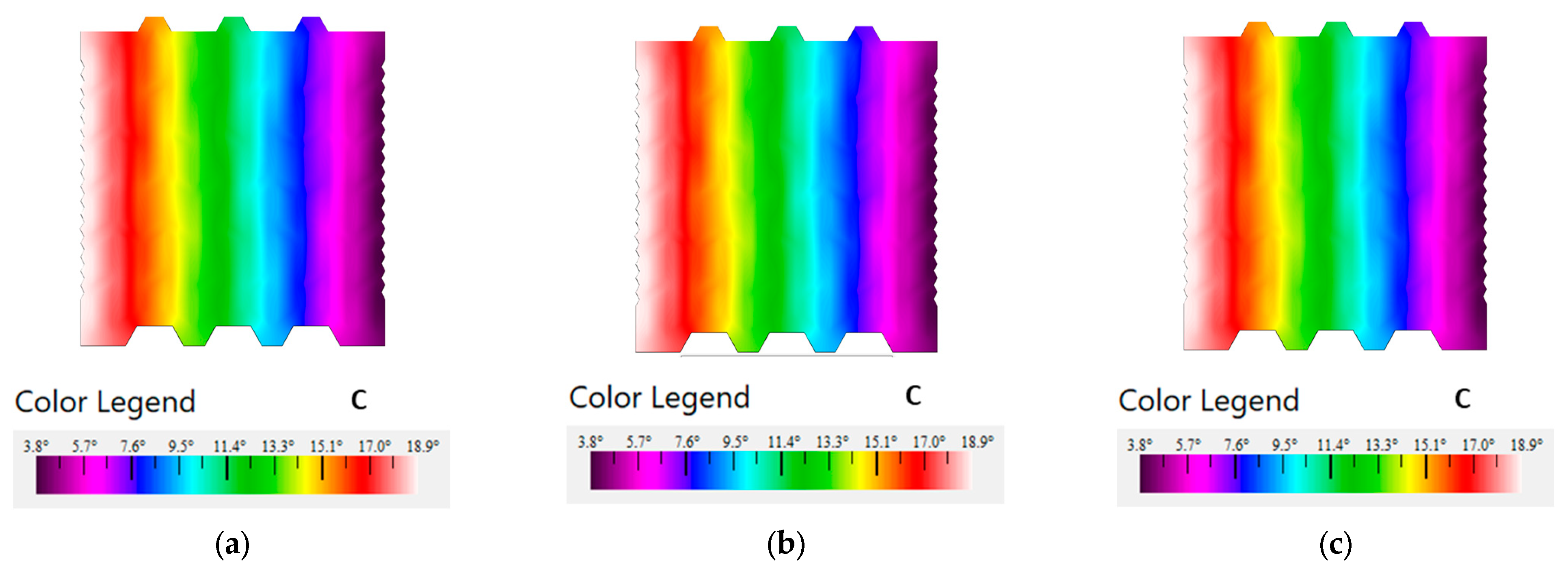
Figure 4, the geometry of the ceramic products and the respective domains are portrayed. The ceramic product is insulated at the bottom and the top side.
In the left-side wall, corresponding to the external wall, a convective heat flux boundary condition was applied, with an external temperature of 0 °C and a heat transfer coefficient of 25 W/(m
2·K). Similarly, in the right-side wall, corresponding to the inner wall, a convective heat flux boundary condition was applied, with a constant temperature of 20 °C and a heat transfer coefficient of 7.69 W/(m
2·K) [
28].
Figure 3.
(a) Ceramic geometry and (b) domains of horizontal hollows brick.
Figure 3.
(a) Ceramic geometry and (b) domains of horizontal hollows brick.
Figure 4.
(a) Ceramic geometry and (b) domains of vertically perforated brick.
Figure 4.
(a) Ceramic geometry and (b) domains of vertically perforated brick.
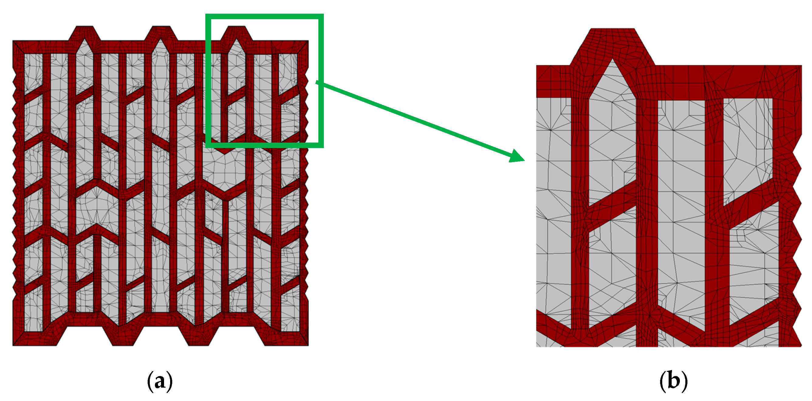
Computational Details
Convergence was assumed when the scaled residuals of the discretized equations fell below a preset tolerance of 10
−6. The thermal problem was solved with the stationary direct solver PARDISO. The grid consisted of 73.864 triangular mesh elements (see
Figure 5 and
Figure 6), with the lowest element quality being equal to 0.62 [
29].
4. Discussion
The present study aimed to investigate the potential of solid waste material as an additive to reduce the density of clay-based mixtures and improve their thermal performance. Three different mixtures were prepared, one with 100% clay material, one with 98% clay material and 2% solid waste material, and another with 92% clay material and 8% solid waste material. The addition of solid waste material resulted in a maximum of 17.3% decrease in the thermal coefficient of the mixtures.
The prepared mixtures were extruded into brick samples and subjected to drying and firing at 900 °C in a pilot brick and tile industry environment. The density and thermal coefficient of the fired clay samples were measured and used to simulate the thermal performance of two different brick designs using computational fluid dynamics (CFD) software. The first design was the typical Greek brick with horizontal hollows, while the second design was a vertical perforated brick, which is a new entrant in the Greek market.
The results of the study, can be seen in
Table 10,
Table 11,
Table 12,
Table 13,
Table 14 and
Table 15, showed that the geometry of the brick was a critical factor that could significantly improve the thermal insulation of a building. Additionally, reducing the density of the final product by incorporating lightweight additives into the production mixture could also play a significant role in enhancing thermal insulation. It was observed that the λ value of the fired product’s clay should be the primary parameter that a brick industry should aim to achieve. Furthermore, changing the molds in vertically perforated bricks could potentially create differences in the production environment.
The incorporation of solid waste material as an additive in clay-based mixtures has shown promising results in both reducing density and enhancing thermal performance. One such waste material, paper sludge, which predominantly consists of organic components like cellulose fibers, has proven beneficial in brick production. When these bricks undergo the firing process, the organic materials within the paper sludge combust and create voids within the clay matrix. These voids serve as channels for the escape of gases, effectively preventing the formation of defects such as cracks or warping that could compromise the structural integrity of the bricks. Therefore, despite the inclusion of paper sludge, the resulting bricks maintain their mechanical strength. This combination of waste material incorporation and optimized brick geometry highlights the potential for sustainable and thermally efficient building practices, as it addresses both the disposal of solid waste and the improvement of thermal insulation in construction. Further research is needed to explore the potential of different solid waste materials as additives in the production of clay-based mixtures and their impact on the thermal performance of buildings.
5. Conclusions
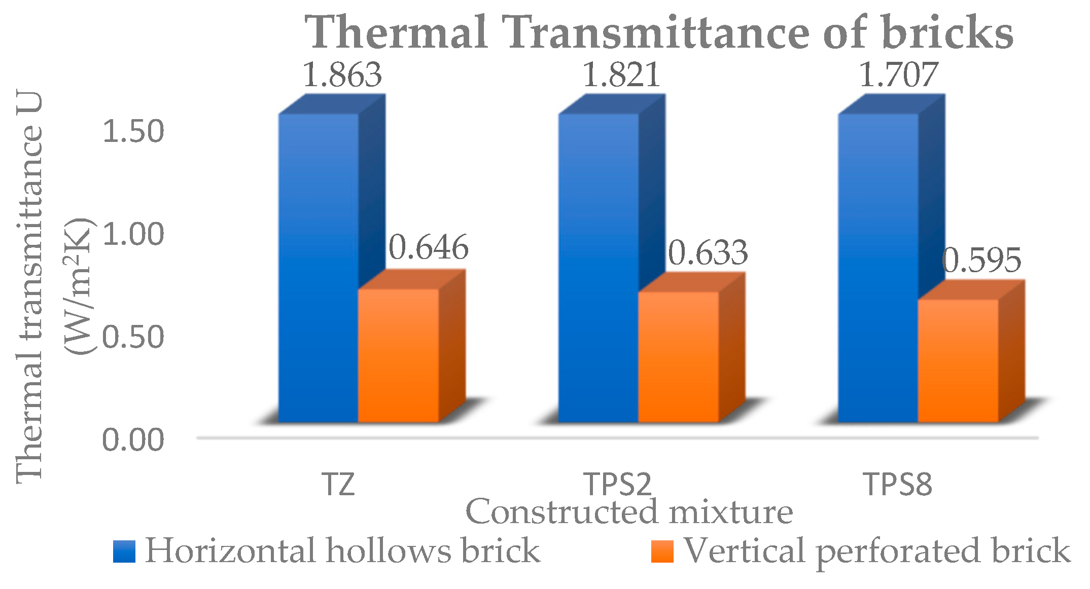
Based on the results presented, it can be concluded that the addition of paper sludge to fired clay material can significantly improve the thermal insulation properties of both individual bricks and masonry walls constructed using these bricks. The use of paper sludge reduced the thermal coefficient of the fired clay material by 17%, which resulted in a reduction of the U value and an increase in the resistance (R) of the bricks and masonry walls.
When comparing the thermal insulation properties of the standard 90 cm horizontal hollow brick of the Greek market to the new entry vertically perforated brick, it was found that while the improvement in the thermal coefficient of the vertically perforated brick was only 3 to 3.5%, there was a significant improvement in the R value of the product (
Figure 9), which presented 188% improvement, and a 65% better U value. Similarly, the masonry wall constructed using the vertically perforated brick showed a significant improvement of 135% in its thermal insulation properties.
It is important to note that the maximum difference range was observed between the horizontal brick without the paper sludge addition and the vertically perforated brick with the paper sludge addition. In this case, the thermal coefficient of the brick presented an 11% deviation, and the U value of the brick improved by 68%. Moreover, the U value of the masonry wall constructed using the vertically perforated brick with the paper sludge addition showed a 61% improvement.
These results suggest that the use of vertically perforated bricks with paper sludge addition could be an effective strategy for improving the thermal insulation properties of masonry walls (
Figure 10). Moreover, the use of paper sludge can help reduce the environmental impact of the manufacturing process of fired clay bricks. The findings of this study could be of significant interest to the construction industry, particularly for builders and architects looking to improve the energy efficiency of buildings while also incorporating sustainable materials. However, the use of paper sludge exceeding 10% in the brick mass creates many difficulties (on the preparation of the product mixture, on the main extruder gear, on the final strength, etc.) and during the cutting process of the samples after extrusion. This is primarily due to the presence of fibers in the paper sludge. The cutting of ceramic brick products in the brick industry is performed using a metal wire, and the fibers tend to adhere to it, resulting in undesired fiber aggregates that affect the intended cutting dimensions of the wet product. This issue is particularly crucial for brick factories, as it may lead to the rejection of products that do not meet market standards.
Further research can be conducted to explore the potential benefits of using paper sludge in other construction materials and techniques.
In conclusion, this study highlights the importance of the geometry of bricks and the addition of solid waste as an additive in improving the thermal performance of clay-based mixtures. The results suggest that the use of lightweight additives and alternative materials in the production of bricks can lead to the development of more energy-efficient buildings. The findings of this study have significant implications for the construction industry and can contribute to sustainable waste management practices. Future research should focus on exploring the potential of different solid waste materials as additives in the production of clay-based mixtures and their impact on the thermal performance of buildings.


