Article

Anodic Performance of Ni–BCZY and Ni–BCZY–GDC Films on BCZY Electrolytes

Graduate School of Science and Engineering, Ehime University, Matsuyama 890-8577, Japan
*
Author to whom correspondence should be addressed.
Ceramics 2023, 6(3), 1850-1860; https://doi.org/10.3390/ceramics6030113
Submission received: 13 July 2023 / Revised: 18 August 2023 / Accepted: 31 August 2023 / Published: 5 September 2023

Abstract

:
Cermet films consisting of Ni, BaCe0.4Zr0.4Y0.2O3−δ (BCZY), and Gd0.1Ce0.9Ox (GDC), specifically, 60 wt%Ni–BCZY, 60 wt%Ni–BCZY–GDC, and 60 wt%Ni–GDC, were formed on BCZY electrolyte supports as anodes of proton ceramic fuel cells (PCFCs). The Ni grain size in these films after sintering at 1450 °C was around 2 μm. The GDC addition did not affect the Ni grain size in the case of the BCZY matrix. The anodic properties greatly depended on the oxide phase composition and worsened with increasing the GDC content. This probably occurred because of the addition of GDC, which has low proton conductivity and inhibited the proton conduction path of BCZY, reducing three-phase boundaries in the anode bulk. Since BCZY has a lower grain growth rate during sintering than BaCe0.8Y0.2O3−δ, the Ni grain growth was likely suppressed by the surrounding Ni grains containing small BCZY grains.

Graphical Abstract

1. Introduction

Achieving carbon neutrality is now one of the global goals, and the use of hydrogen energy is one of the key technologies. Fuel cells are power generators that can make the most of hydrogen energy without releasing CO2. Among them, solid oxide fuel cells (SOFCs) are composed of ceramics, are highly active, and have the highest power generation efficiency because they can operate at high temperatures (~800 °C) [1]. Another advantage of SOFCs is that platinum used as an electrode material for polymer electrolyte membrane fuel cells (PEMFCs) is not required. Platinum is extremely scarce and expensive, which drives up the cost of PEMFCs. Since platinum is deactivated by combining with CO contained in fuel, it is necessary to remove CO in fuel hydrogen to an extremely low concentration [2]. On the contrary, CO can be used directly as a fuel in SOFCs, which significantly reduces the cost of the hydrogen production process [3].
However, operating at high temperatures over 700 °C leads to undesired chemical reactions between electrode and electrolyte [4] and a decrease in activity due to coarsening of Ni grains [5], hampering long-term stability. Further, thermally durable metallic parts such as Ni-alloys should be used, which increases the cost of the cell module. For these reasons, extensive research has been recently conducted on the intermediate-temperature operation of fuel cells at 500~600 °C. It is, however, difficult for the conventional yttria-stabilized zirconia (YSZ) electrolyte-based SOFCs to operate stably at such low temperatures because the resistance of YSZ is predominantly large at such low temperatures. The electrical conductivity of 8 mol%YSZ at 600 °C is as low as the level of around 10−3 S cm−1 [6]. Gadolinia-doped ceria (GDC) [7] and (La,Sr)(Ga,Mg)O3-based oxides [8] have electrical conductivity several times higher than that of YSZ, but still the order of 10−2 S cm−1 at 600 °C.
In recent years, next-generation ceramic fuel cells using proton-conducting oxides instead of oxide ion conductors as electrolytes, i.e., proton ceramic fuel cells (PCFCs), are being developed [9,10]. For example, proton-conducting perovskite-type oxides such as yttrium-doped barium cerates (BaCe0.8Y0.2O3−δ (BCY)) [11,12] and zirconates (BZY) [13] have a low activation energy and high proton conductivity even at ~600 °C; conductivity of BCY with 97% density at 600 °C is about 2 × 10⁻² S cm−1 [14], one order of magnitude greater than that of YSZ at the same temperature. PCFCs using proton conducting oxides, therefore, have a great potential to operate at below 600 °C. Operating a cell at below 600 °C allows us to use cheaper metal materials, such as stainless steel. Another advantage of PCFC is that no water is, in principle, generated at the fuel electrode, so the hydrogen fuel can keep its high concentration.
However, despite its high proton conductivity, BCY is chemically unstable at high temperatures, mainly because of its reaction with CO2 [15,16]. BZY is more chemically stable, but it has low sinterability and requires high-temperature sintering (>1600 °C) to turn into dense bodies [17,18]. BaCe0.4Zr0.4Y0.2O3−δ (BCZY), which has both Ce and Zr at the B-site of the perovskite structure (ABO3), is expected to be a proton-conducting oxide combining the high proton conductivity of BCY and the high chemical stability of BZY [19].
Cermets consisting of Ni and a proton-conducting oxide, such as Ni–BCY [20] and Ni–BCZY [21], are frequently used as the anode materials in PCFCs. Studies on PCFC anodes have demonstrated that the proton conductivity of the proton-conducting oxide phase strongly affects the anodic properties. An anode-supported PCFC consisting of thin proton-conducting film attached to an anode support is a low-resistance cell structure [22]. We previously succeeded in fabricating a dense ~10 μm-thick BCY film on a Ni–BCY anode support via electrophoretic deposition followed by sintering at 1450 °C [23]; the area specific resistance of the BCY film was as low as 0.58 Ω cm2. However, the co-sintering of the anode support with the electrolyte film resulted in Ni grain coarsening in the anode and/or excessive densification of its support, which increased the polarization resistance of the anode. Microstructure, such as porosity, is the factor that can determine the electrode properties [24,25,26,27]. So far, many studies have been performed to derive an optimal structure for Ni-cermet anodes of PCFC. Several studies have investigated the polarization resistance of anodes porosity-controlled by adding a porogen, such as starch. Nasani et al. [26] investigated the influence of the porosity of the anode on the polarization resistance of the Ni–BZY anode. Taillades et al., [27] controlled the porosity and microstructure of Ni–BCY anode using a gelled starch as a pore former. They revealed that the use of gelling starch gives rise to homogeneous open pores and higher metallic conductivity. Ni grain size distribution is also a decisive factor for anode catalytic activity. Thus, proper porosity control is an essential factor for high anode activity. Moreover, since Ni-cermets containing the proton conducting oxides mentioned above are generally sintered at high temperatures, it is concerning that Ni grain growth after the sintering reduces the catalytic activity. Infiltration of Ni solution into a pre-sintered oxide scaffold has been elaborated [28,29,30]. This technique allows the sintering of the impregnated Ni or other catalyst precursors at low temperatures to achieve a homogeneous distribution of Ni nanoparticles and to suppress NiO diffusion into the oxide phase. Fine particles dispersed may exhibit high initial catalytic properties, but the concern of Ni agglomeration during long-term operation cannot be eliminated. We previously found that the grain growth in a BCY-dense sinter was significantly suppressed by adding GDC [31]. Moreover, the addition of Gd0.1Ce0.9Ox (GDC) as a third component in Ni–BCY sintering, yielding Ni–BCY–GDC, remarkably suppresses the growth of Ni grains after sintering at 1450 °C, and this phenomenon is related to the volume fraction and grain size of the surrounding oxide matrix [32]. NiO is frequently used as a sintering aid of proton-conducting oxides [33,34]; therefore, its presence may promote the sintering of the BCY phase, resulting in NiO grain growth as well. The reduction of Ni grain size by GDC addition significantly improves the electronic conductivity of the Ni metal phases. Furthermore, the addition of GDC significantly enhances the CO2 resistance of BCY [31], and it also reduces the BCY grain size, having a positive effect on the Ni grain size after the high-temperature sintering and the CO2 resistance.
GDC is a good oxide ion conductor and exhibits electron conduction associated with the reduction of Ce4+ to Ce3+ in a reducing atmosphere [35]. Nonetheless, since its proton conductivity is extremely low [36], adding GDC to Ni–BCY may decrease the proton transference number of the oxide phase. The addition of GDC, therefore, can have the effect of both refinements of Ni and a decrease in proton conductivity of the anode of PCFC. In this study, we investigated the effects of GDC addition on the anode activity of Ni-anode films of an electrolyte-supported PCFC.
In this study, BCZY instead of BCY was used as the electrolyte and secondary phase of the Ni-anode of PCFC, and the effect of GDC addition on the anode morphology and electrode properties was investigated for Ni–BCZY–GDC with a weight ratio of 6:2:2 and compared to Ni–BCZY and Ni–GDC. BCZY–GDC composites have been examined as a dual-phase hydrogen separation membrane where GDC acted as an electronic conduction phase in the reducing atmosphere [37]. It is anticipated that the reduction of Ce4+ to Ce3+ causes lattice expansion and mechanical instability of the film. Mortalò et al. [38], however, revealed by the phase analysis in the operating temperature that GDC is less reducible in the presence of BCZY, resulting in high mechanical stability under reducing conditions at high temperatures. Therefore, Ni-BCZY-GDC is also expected to be a promising anode material for PCFC, which has high Ni dispersion and chemical and mechanical stability even at high temperatures.

2. Experimental Section

2.1. Sample Preparation

2.1.1. Ceramic Phase

First, BCZY was prepared through a solid-state reaction between the following starting materials at the stoichiometric amounts: BaCO3 (>99.9%), CeO2 (>99.9%), ZrO2 (>99%), and Y2O3 (>99.9%) powders (Kojundo Kagaku, Sakado, Japan). These chemicals were all used without further purification. First, the mixed powders were pressed into a disk at 15 MPa for 30 s using a uniaxial pressure molding apparatus and then fired at 1200 °C in air for 4 h. The disk was crashed coarsely and balled-milled in ethanol for 2 h using Nylon pot and zirconia balls with a diameter of ~5 mm.

2.1.2. NiO Cermet Anodes

As anode materials, NiO–BCZY, NiO–BCZY–GDC, and NiO–GDC mixtures were first prepared. The NiO amount was adjusted to obtain 60 wt% Ni metal after the reduction process. First, the powders of NiO (d = 0.5 μm, Sumitomo Metal Mining Co., Ltd., Tokyo, Japan) and BCZY or GDC (AGC Seimi Chemical, Chigasaki, Japan) were weighed with a weight ratio of 66:34 for NiO–BCZY, 66:17:17 for NiO–BCZY–GDC and 66:34 for NiO–GDC. These weight ratios correspond to those of 60:40, 60:20:20, and 60:40 for Ni–BCZY, Ni–BCZY–GDC, and Ni–GDC, respectively. The weighed powders and zirconia balls with a diameter of 10 mm were placed in a Nylon pot and mixed by the ball milling in dry for 2 h. The mixed powders were calcined in air at 1000 °C for 5 h. The product was crushed via ball milling in ethanol, and then the dried powders were pressed into a pellet by a uniaxial press at a pressure of 20 MPa. The obtained pellets were calcined in the air at 1300 °C for 4 h, and the resulting solid was again crushed by the ball milling for 24 h.

2.1.3. Test Cells

First, a BCZY powder was pressed into pellets at 20 MPa, calcined in air at 1500 °C for 4 h, and used as the proton-conducting electrolyte support having a diameter of 10 mm and a thickness of 0.6 mm. In order to avoid the evaporation of Ba element, the BCZY disks were calcined while immersed in a BCZY powder having an identical elemental composition.
The anode powders were mixed with α-terpineol (Kanto Chemical, Tokyo, Japan) to form a slurry and printed on one surface of the prepared electrolyte pellets by using a table coater (TC-3, Mitsui Electric, Fukuoka, Japan). The thickness of the anode films was adjusted with the variable applicator (AP-150d, Mitsui Electric) to 20 μm; the printed anodes were sintered at 1450 °C for 4 h. Next, counter and reference electrodes were formed with platinum paste (TR-7907, Tanaka Precious Metal, Tokyo, Japan) on the opposite surface of the pellets and fired at 1000 °C for 1 h. The areas of the anode, counter electrode, and reference electrode were 0.28, 0.28, and 0.03 cm2, respectively. Pt paste was further applied over the anode surface as a current collector.

2.2. Measurements

2.2.1. Anode Characterization

The cermet powders and sintered pellets were characterized with an X-ray diffractometry (XRD, X’Pert Pro MPD, PANalytical, Malvern, UK) system using Cu Kα X-ray. The morphology and elemental composition of the anode surfaces were evaluated via scanning electron microscopy and energy-dispersive X-ray spectroscopy (SEM-EDS, JSM-6510LA, JEOL, Tokyo, Japan). Anode pellets for XRD and SEM-EDS analysis were sintered in air and then subjected to hydrogen reduction to reduce NiO into Ni at 800 °C for 2 h under a 4% H2/N2 flow.

2.2.2. Impedance Analysis

Three-terminal cells were prepared based on yttrium-stabilized zirconia and BCZY support disks. Ni cermet films were deposited by slurry coating on the disks, and Pt counter and reference electrodes were formed on the other side of the disks with Pt paste. Prior to the impedance test, 4% H2/N2 gas was passed through the anode side with a flow rate of 50 mL min−1 at 800 °C for 2 h to reduce NiO. For the impedance tests, the anode side was exposed to 4% H2/N2 fuel gas after passing through a water reservoir at room temperature, with a flow rate of 50 mL min−1, while the reference and counter electrodes were exposed to compressed air with the identical flow rate. Impedance spectra were recorded under an open-circuit voltage with an AC amplitude of 50 mV in the frequency range between 1 × 10⁶ and 1 × 10⁻² Hz using the impedance analyzer (SI 1260, Solartron Analytical, Farnborough, UK) connected with the potentiostat/galvanostat (SI 1287, Solartron Analytical).

3. Results and Discussion

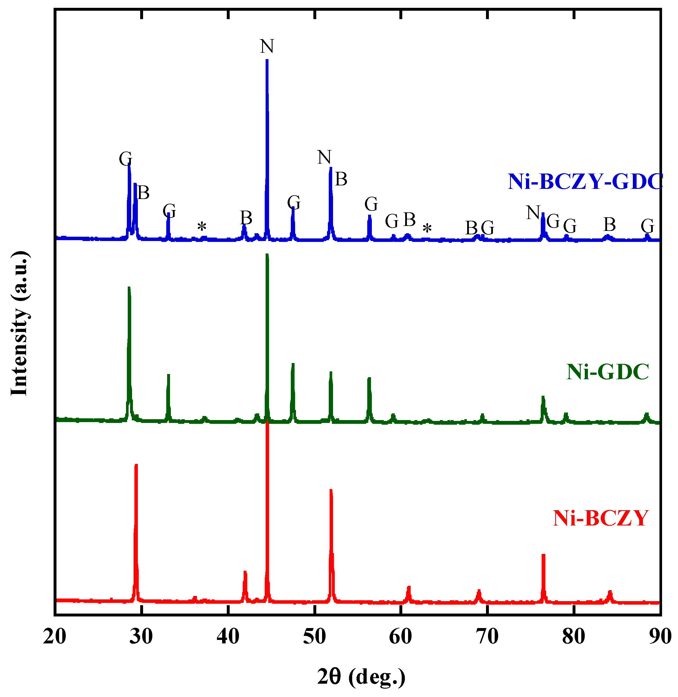
3.1. XRD Analysis of Ni–BCZY–GDC

The Ni cermet powders were characterized by XRD. Figure 1 shows the XRD patterns of the cermet disks sintered at 1450 °C followed by the H2 reduction. The XRD pattern of BCZY revealed cubic symmetry and a Pm-3 m space group, as reported elsewhere [39]. The Ni–BCZY and Ni–BCZY–GDC and Ni–GDC powders were identified as simple mixtures of Ni metal, the constituent oxides. Very weak peaks for NiO were observed, but almost all Ni was reduced under the given conditions.

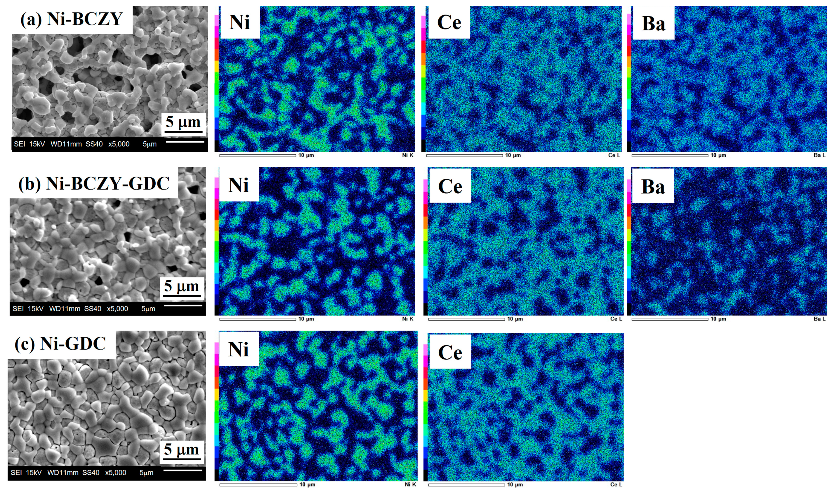
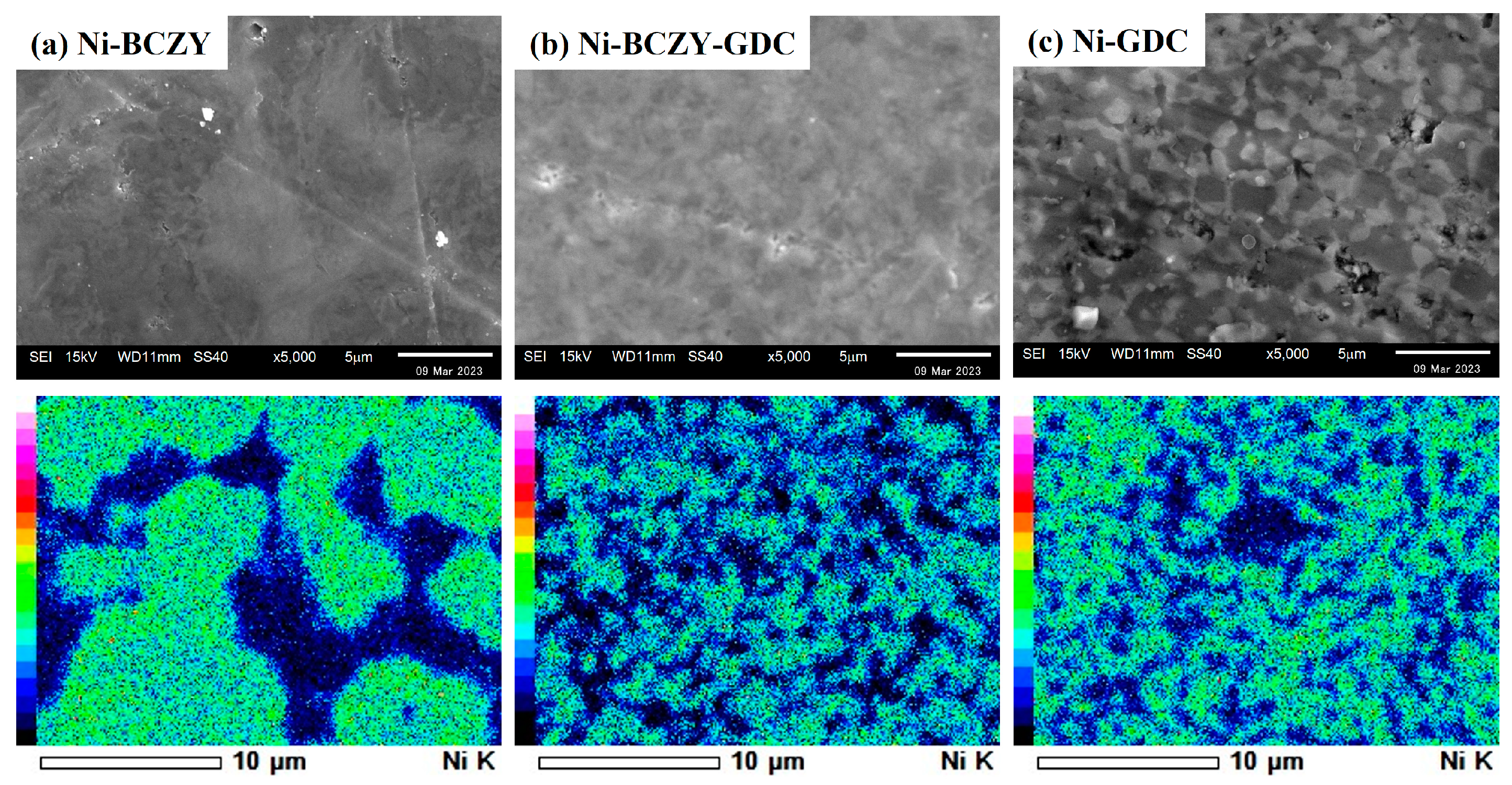
3.2. Anode Surface Morphology

Figure 2 shows the SEM images and corresponding EDS elemental maps of the anode surfaces. Micrometer-sized pores are scattered on the surface of Ni–BCZY and Ni–BCZY–GDC films, and pores are particularly conspicuous in Ni–BCZY. Ni–GDC film showed a relatively dense phase on its surface. Since pore size tends to be small with an increase in GDC content, GDC probably acts as a sintering aid. In all the films, nano-sized fine pores were observed in the Ni grains, which can be attributed to a trace of oxygen dissociation from NiO accompanying the hydrogen reduction. According to the EDS analysis, Ni grains with a grain size of a few micrometers were connected and surrounded by the oxide phases. The mean size of Ni grains was evaluated from the EDS images for the randomly selected 30 grains; the size of an ellipsoidal grain was defined as the average of the short and long diameters. Table 1 lists the mean sizes of the Ni grains in the anodes derived from the elemental mapping, which had similar values (~2 μm) among the three anodes. In the previous study [32] on Ni grain growth in sintered Ni–BCY and Ni–BCY–GDC disks, the mean Ni grain sizes in those containing 60 wt% Ni after sintering at 1450 °C were 6.4 and 3 μm, respectively. In the present study, porous anode films of Ni–BCZY and Ni–BCZY–GDC exhibited smaller Ni grain size after sintering at 1450 °C than the dense Ni-cermets with or without adding GDC. Figure 3 displays the EDS Ni elemental maps of the surface of the Ni–BCZY, Ni–BCZY–GDC, and Ni–GDC disks sintered at 1450 °C. Despite being sintered at the same temperature as the slurry-coated films in Figure 2, the disk compact had a denser form than the slurry-coated anode membranes. This probably occurred because the bulk density of the disk molding was increased by the uniaxial pressing process. The Ni–BCZY sintered disk apparently has a larger grain size than the porous film, suggesting that the small size of Ni grains in the Ni–BCZY anode film is affected by the existence of pores. On the other hand, Ni grain growth is highly suppressed in the case of Ni–BCZY–GDC and Ni–GDC. Therefore, the slurry-coated films of Ni–BCZY–GDC and GDC are affected in their Ni grain sizes by pores and/or GDC phase. Grain growth suppression by a secondary phase, that is, solid particles and/or pores, has been interpreted as the pinning effect retarding grain boundary migration of the matrix phase. In general, there is the following relationship between grain size and pinning as the Zener Equation (1).
D = α ( p r ) 1
where D is crystal grain size, r is the diameter of the secondary phase, p is the volume fraction of the secondary phase, and α is a geometric factor. In our previous study [32], a linear relationship was obtained between D (Ni grain size in Ni–BCY–GDC) and r/p (grain size of GDC over volume fraction of GDC) as predicted in Equation (1). This could be due to the pinning force by the GDC phase. If the secondary phase involved in Equation (1) is pore, p is porosity, and r is pore size. If Ni grain growth in Ni–BCZY is inhibited by pores, the Ni grain size should depend on the parameter p/r of the pores. A quantitative discussion on porosity and Ni grain size is necessary in the future.
Liu et al. [40] developed a model for pore-controlled inhibition of grain growth and applied it to grain sizes in alumina, tungsten, and uranium oxide porous media. They obtained a linear relationship between pore surface area per unit volume and inverse particle size. In a similar mechanism, Ni grain growth, in this study, is possibly inhibited by the pores. In the case of Ni–GDC, the morphology is denser than the other two, so Ni/GDC grain boundary contacts could act as the inhibitor of Ni grain growth.

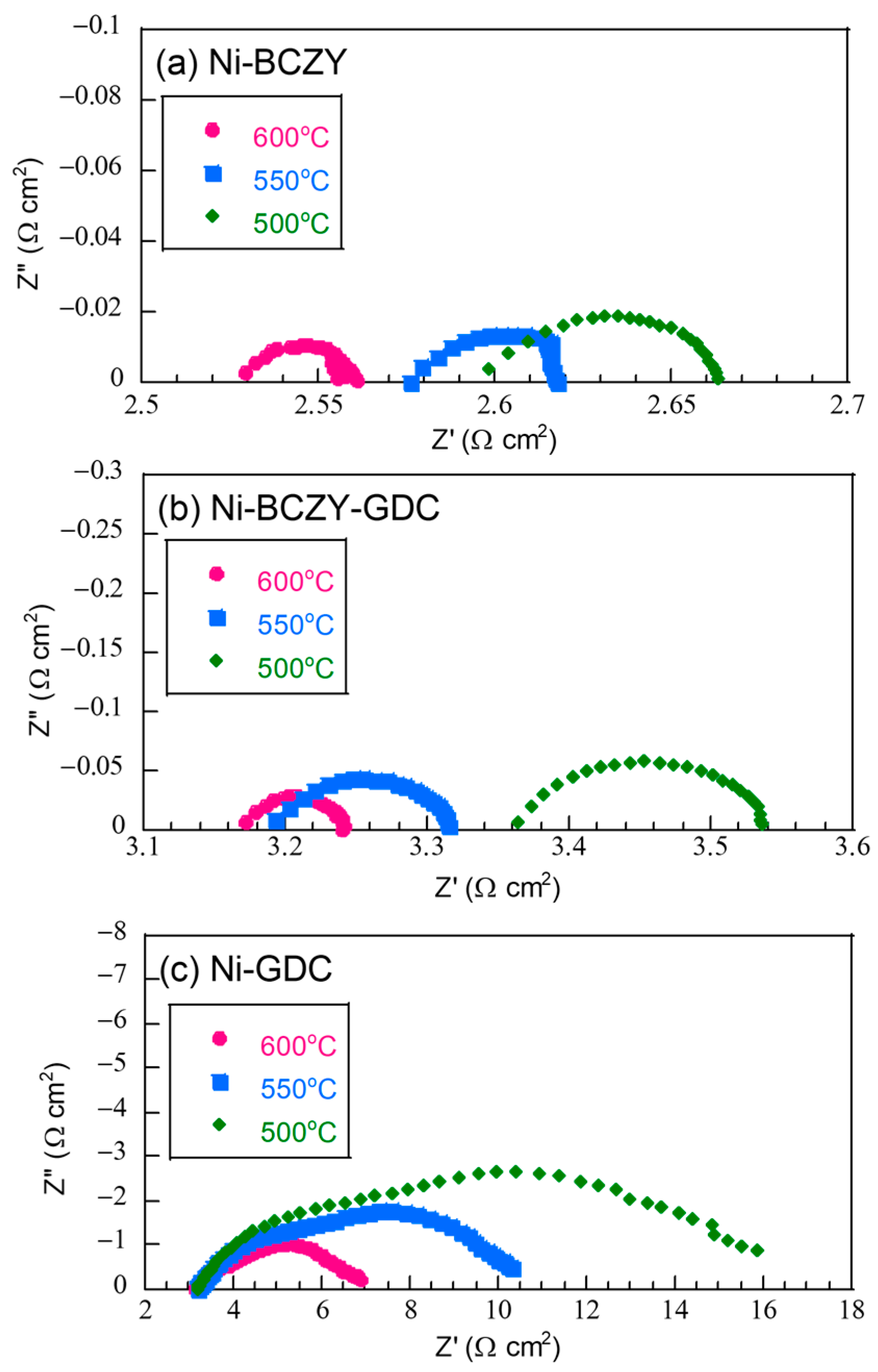
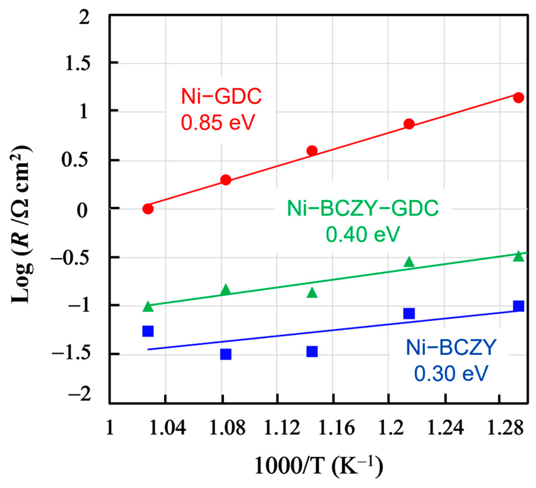
3.3. Anodic Properties

Figure 4 displays the Nyquist plots of the half-cells based on the fabricated anode films on a BCZY electrolyte substrate in a three-terminal configuration. Each plot had an ohmic component and a flattened arc; the flattened arcs likely consisted of overlapping arc components. Since the separation of the arc components was unclear, the entire arc components were evaluated as the electrode resistance. The ohmic component on the high-frequency side, instead, was attributed to the resistance from the electrolyte and lead wires of the cell holder. The ohmic resistance was in the range of 2.5–3.5 Ω cm2 and decreased with increasing the temperature. Since the thickness of the BCZY electrolyte disk was 0.06 cm, the apparent resistivity of the ohmic components was around 41.7–58.3 Ω cm2, which is comparable with the values reported for BCZY in a wet H2 atmosphere [41]. Moreover, the resistance values of the arc component attributed to the anode resistance decreased with increasing the temperature. However, regardless of the temperature, the anode resistance followed this order: Ni–GDC > Ni–BCZY–GDC > Ni–BCZY. The anode resistance of Ni–GDC was the largest by far.
Figure 5 shows the temperature dependences of the anode resistances evaluated from the total width of arcs in the Nyquist plots in the range of 500–600 °C, along with the derived activation energies. Compared the activation energies of Ni–BCZY and Ni–BCZY–GDC to that of Ni–GDC, the latter value is much larger than those of formers. Since the Ni grain size was about the same for the three anodes, the anode resistance likely reflects the difference in their oxide phases as it increases along with the GDC content in them. In the Ni–BCZY and Ni–BCZY–GDC anodes, the BCZY phase probably contributed to the anode resistance reduction as a proton-conducting phase because its presence expanded the reaction field within the electrode bulk. GDC is a good oxide ion conductor, but it can be a minor electric carrier in wet-condition protons formed by water dissociation. Zhu et al. [35] investigated proton conduction in wet conditions. According to their report, the conductivity at 700 °C in 81%RH is ~2.7 × 10⁻² S cm−1; however, the transport number of proton conduction does not exceed 2.63%. Their results suggest that the protonic conductivity of GDC at 700 °C is much smaller than that of BCZY. Therefore, we can assume that the GDC phase hardly contributed to proton conduction in Ni–BCZY–GDC, and, thus, the GDC addition apparently inhibited the proton conduction of the anode. In Ni–BCZY–GDC, the volume fractions of the BCZY and GDC phases were about 0.32 and 0.20, respectively. According to the Ba elemental maps shown in Figure 2, the Ba distribution intensity was smaller in Ni–BCZY–GDC than in Ni–BCZY. Nonetheless, the spots of Ba (as detected via EDS) originated from the BCZY grains apparently aggregated to form grain chains in the anode. This is probably why the anode characteristics of Ni–BCZY–GDC were inferior but close to those of Ni–BCZY. The activation energies of Ni–BCZY and Ni–BCZY–GDC anodes are 0.30 and 0.40 eV, respectively, and those values are close to that of proton conduction in BCZY [41]. We tentatively consider that those two values are significantly different. Baral [42] reported the proton conductivity of BCZY. The activation energy for the total conductivity of BCZY was evaluated as 0.48 eV in a temperature range of 250–320 °C and 0.30 eV in 400–600 °C. Proton conductivity in the former range is governed by the conduction in grain boundary, and the latter is in bulk. The volume fractions of BCZY in the cermets are 40 and 20% in Ni–BCZY and Ni–BCZY–GDC, respectively. The higher activation energy in Ni–BCZY–GDC is probably due to the fact that proton conduction at the grain boundaries contributes to the total conductivity more than that in Ni–BCZY. It is deduced that proton conduction in the anode layer is a rate-determining process in Ni–BCZY and Ni–BCZY–GDC anodes. On the other hand, a three-phase boundary is confined to the interface between the electrode and electrolyte layers in the case of Ni-GDC because proton conductivity in the electrode layer is negligibly small. The activation energy of Ni–GDC is 0.85 eV, significantly higher than those of the other two anodes. A possible rate-determining process is hydrogen transfer to the three-phase boundary via surface and/or bulk diffusion of a hydrogen atom and gas diffusion through the pores.
Our results demonstrate that the use of BCZY as the oxide phase suppresses Ni grain growth after high-temperature sintering compared to BCY. In the case of BCY, the GDC addition significantly suppresses Ni grain growth, but such an effect was not observed in BCZY, where, instead, the proton conduction was inhibited, lowering the anodic properties.

4. Conclusions

This study aimed to establish a method for preparing a PCFC anode film where Ni grain growth after high-temperature sintering is highly suppressed. Ni–BCZY, Ni–BCZY–GDC, and Ni–GDC films containing 60 wt% Ni were prepared by the solid-state reaction process and tested as an anode of a BCZY-electrolyte-supported PCFC by using impedance spectroscopy. Press-formed Ni-cermet discs showed a dense morphology by sintering at 1450 °C. Remarkable Ni grain growth was observed in Ni–BCZY after the sintering. In contrast, grain sizes of Ni and the oxide phases were significantly smaller in the GDC–added cermets than in Ni–BCZY, suggesting that the addition of GDC to Ni–BCZY has the effect of inhibiting the grain growth of the tissue. Ni-cermet films formed with slurry coating on a BCZY substrate showed a porous morphology even after sintering at 1450 °C. In the porous cermet films, the Ni size was approximately 2 μm with or without GDC, suggesting that Ni grain growth, in this case, is mainly inhibited by pores.
Anode resistance in 4% H2 was evaluated with the three-terminal impedance analyses and resulted in the order of Ni–BCZY < Ni–BCZY–GDC << Ni–GDC and GDC addition rather increases anode resistance. Since the proton conductivity of GDC is much smaller than that of BCZY, the proton conductivity of the oxide phase greatly contributed to the properties of the Ni–BCZY system. In this study, the amount of GDC in Ni–BCZY–GDC is equivalent to that of BCZY, that is 20 wt%. From the viewpoint of anodic property in the short term, GDC is considered not to be necessary in the porous phase anode. However, in our previous result, GDC addition to the BCZY phase prevented BaO from carbonization under the existence of CO2. Therefore, we believe that the effect of adding reduced GDC to Ni–BCZY–GDC is still worth investigating in terms of short-term and long-term stability.

Author Contributions

Conceptualization, Y.I.; methodology, Y.I.; validation, Y.I. and H.A.; formal analysis, Y.K. and S.O.; investigation, Y.I. and Y.K.; resources, Y.I.; data curation, Y.K. and S.O.; writing—original draft preparation, Y.I.; writing—review and editing, Y.I.; supervision, Y.I.; project administration, Y.I.; funding acquisition, Y.I. All authors have read and agreed to the published version of the manuscript.

Funding

This research received the external funding from JSPS KAKENHI (Grant Number JP22K05288).

Institutional Review Board Statement

Not applicable.

Informed Consent Statement

Not applicable.

Data Availability Statement

Not applicable.

Acknowledgments

This research was supported by Grants-in-Aid for JSPS KAKENHI (Grant Number JP22K05288) and the Research Unit of Regional e-Fuel (ReFuel) at Ehime University.

Conflicts of Interest

The authors declare no conflict of interest.

References

  1. Singhal, S.C. Advances in solid oxide fuel cell technology. Solid State Ion. 2000, 135, 305–313. [Google Scholar] [CrossRef]
  2. Antolini, E. Recent developments in polymer electrolyte fuel cell electrodes. J. Appl. Electrochem. 2004, 34, 563–576. [Google Scholar] [CrossRef]
  3. Wang, W.; Su, C.; Wu, Y.; Ran, R.; Shao, Z. Progress in solid oxide fuel cells with nickel-based anodes operating on methane and related fuels. Chem. Rev. 2013, 113, 8104–8151. [Google Scholar] [PubMed]
  4. Zhang, L.; Chen, G.; Dai, R.; Lv, X.; Yang, D.; Geng, S. A review of the chemical compatibility between oxide electrodes and electrolytes in solid oxide fuel cells. J. Power Sources 2021, 492, 229630. [Google Scholar] [CrossRef]
  5. Simwonis, D.; Tietz, F.; Stöver, D. Nickel coarsening in annealed Ni/8YSZ anode substrates for solid oxide fuel cells. Solid State Ion. 2000, 132, 241–245. [Google Scholar] [CrossRef]
  6. Minh, N.Q.; Takahashi, T. Science and Technology of Ceramic Fuel Cells; Elsevier: Amsterdam, The Netherlands, 1995. [Google Scholar]
  7. Steele, B.C.H. Appraisal of Ce1−yGdyO2−y/2 electrolytes for IT-SOFC operation at 500 °C. Solid State Ion. 2000, 129, 95–110. [Google Scholar] [CrossRef]
  8. Huang, P.; Petric, A. Superior oxygen ion conductivity of lanthanum gallate doped with strontium and magnesium. J. Electrochem. Soc. 1996, 143, 1644–1648. [Google Scholar] [CrossRef]
  9. Duan, C.; Tong, J.; Shang, M.; Nikodemski, S.; Sanders, M.; Ricote, S.; Almansoori, A.; O’Hayre, R. Readily processed protonic ceramic fuel cells with high performance at low temperature. Science 2015, 349, 1321–1326. [Google Scholar] [CrossRef]
  10. Kreuer, K.-D.; Paddison, S.J.; Spohr, E.; Schuster, M. Transport in proton conductors for fuel-cell applications: Simulations, elementary reactions, and phenomenology. Chem. Rev. 2004, 104, 4637–4678. [Google Scholar] [CrossRef]
  11. Guan, J.; Dorris, S.E.; Balachandran, U.; Liu, M. Transport properties of BaCe0.95Y0.05O3-α, mixed conductors for hydrogen separation. Solid State Ion. 1997, 100, 45–52. [Google Scholar] [CrossRef]
  12. Suksamai, W.; Metcalfe, I.S. Measurement of proton and oxide ion fluxes in a working Y-doped BaCeO3 SOFC. Solid State Ion. 2007, 178, 627–634. [Google Scholar] [CrossRef]
  13. Katahira, K.; Kohchi, Y.; Shimura, T.; Iwahara, H. Protonic conduction in Zr-substituted BaCeO3. Solid State Ion. 2000, 138, 91–98. [Google Scholar] [CrossRef]
  14. Khani, Z.; Taillades-Jacquin, M.; Taillades, G.; Marrony, M.; Jones, D.J.; Rozière, J. New synthesis of nanopowders of proton conducting materials. A route to densified proton ceramics. J. Solid State Chem. 2009, 182, 790–798. [Google Scholar] [CrossRef]
  15. Tanner, C.W.; Virkar, A.V. Instability of BaCeO3 in H2O-containing atmospheres. J. Electrochem. Soc. 1996, 143, 1386–1389. [Google Scholar] [CrossRef]
  16. Li, Y.; Su, P.C.; Wong, L.M.; Wang, S. Chemical stability study of nanoscale thin film yttria-doped barium cerate electrolyte for micro solid oxide fuel cells. J. Power Sources 2014, 268, 804–809. [Google Scholar] [CrossRef]
  17. Yamazaki, Y.; Hernandez-Sanchez, R.; Haile, S.M. Cation non-stoichiometry in yttrium-doped barium zirconate: Phase behavior, microstructure, and proton conductivity. J. Mater. Chem. 2010, 20, 8158–8166. [Google Scholar] [CrossRef]
  18. Magrez, A.; Schober, T. Preparation, sintering, and water incorporation of proton conducting Ba0.99Zr0.8Y0.2O3−δ: Comparison between three different synthesis techniques. Solid State Ion. 2004, 175, 585–588. [Google Scholar] [CrossRef]
  19. Sawant, P.; Varma, S.; Wani, B.N.; Bharadwaj, S.R. Synthesis, stability and conductivity of BaCe0.8-xZrxY0.2O3-δ as electrolyte for proton conducting SOFC. Int. J. Hydrog. Energy 2012, 37, 3848–3856. [Google Scholar] [CrossRef]
  20. Taillades, G.; Pers, P.; Batocchi, P.; Taillades, M. Advanced electrodes for intermediate temperature proton conducting fuel cell. ECS Trans. 2013, 57, 1289–1296. [Google Scholar] [CrossRef]
  21. Shen, C.-T.; Lee, Y.H.; Xie, K.; Yen, C.P.; Jhuang, J.W.; Lee, K.R.; Lee, S.W.; Tseng, C.J. Correlation between microstructure and catalytic and mechanical properties during redox cycling for Ni-BCY and Ni-BCZY composites. Ceram. Int. 2017, 43, S671–S674. [Google Scholar] [CrossRef]
  22. Nasani, N.; Ramasamy, D.; Sikhalev, S.; Kovalevsky, A.V.; Fagg, D.P. Fabrication and electrochemical performance of a stable, anode supported thin BaCe0.4Zr0.4Y0.2O3-δ electrolyte protonic ceramic fuel cell. J. Power Sources 2015, 278, 582–589. [Google Scholar] [CrossRef]
  23. Itagaki, Y.; Yamamoto, Y.; Aono, H.; Yahiro, H. Anode-supported SOFC with thin film of proton-conducting BaCe0.8Y0.2O3-a by electrophoretic deposition. J. Ceram. Soc. Jpn. 2017, 125, 528–532. [Google Scholar] [CrossRef]
  24. Park, Y.-F.; Ji, H.I.; Kim, B.-K.; Lee, J.-H.; Lee, H.-W.; Park, J.-S. Pore structure improvement in cermet for anode-supported protonic ceramic fuel cells. Ceram. Int. 2013, 39, 2581–2587. [Google Scholar] [CrossRef]
  25. Klemensø, T.; Thydén, K.; Chen, M.; Wang, H.-J. Stability of Ni-yttria stabilized zirconia anodes based on Ni-impregnation. J. Power Sources 2010, 195, 7295–7301. [Google Scholar] [CrossRef]
  26. Nasani, N.; Ramasamy, D.; Brandão, A.D.; Yaremchenko, A.A.; Fagg, D.P. The impact of porosity, pH2 and pH2O on the polarisation resistance of Ni–BaZr0.85Y0.15O3−δ cermet anodes for Protonic Ceramic Fuel Cells (PCFCs). Int. J. Hydrog. Energy 2014, 39, 21231–21241. [Google Scholar] [CrossRef]
  27. Taillades, G.; Batocchi, P.; Essoumhi, A.; Taillades, M.; Jones, D.J.; Rozière, J. Engineering of porosity, microstructure and electrical properties of Ni–BaCe0.9Y0.1O2.95 cermet fuel cell electrodes by gelled starch porogen processing. Microporous Mesoporous Mater. 2011, 145, 26–31. [Google Scholar] [CrossRef]
  28. Yildirim, F.; Timurkutluk, C.; Timurkutluk, B. Optimizing infiltration parameters of nanostructured anode electrode in solid oxide fuel cells. Ceram. Int. 2023, 49, 23642–23653. [Google Scholar] [CrossRef]
  29. Han, D.; Kuramitsu, A.; Onishi, T.; Noda, Y.; Majima, M.; Uda, T. Fabrication of protonic ceramic fuel cells via infiltration with Ni nanoparticles: A new strategy to suppress NiO diffusion & increase open circuit voltage. Solid State Ion. 2020, 345, 115189. [Google Scholar]
  30. Kim, S.K.; Hwang, S.H.; Nam, J.-T.; Park, J.-S. Improvement of Ni-Cermet performance of protonic ceramic fuel cells by catalyst. Ceram. Int. 2021, 47, 21083–21089. [Google Scholar] [CrossRef]
  31. Itagaki, Y.; Hiraoka, A.; Aono, H.; Yahiro, H. Hydrogen permeation of BaCe0.80Y0.20O3−δ–Gd0.1Ce0.9Ox dual-phase membranes. J. Ceram. Soc. Jpn. 2017, 125, 338–342. [Google Scholar] [CrossRef]
  32. Itagaki, Y.; Cui, J.; Tani, Y.; Aono, H.; Yahiro, H. Inhibition of Ni grain growth in Ni-BCY anode substrate for solid oxide fuel cell. ECS Trans. 2019, 91, 1963–1971. [Google Scholar] [CrossRef]
  33. Tong, J.; Clark, D.; Hoban, M.; O’Hayre, R. Cost-effective solid-state reactive sintering method for high conductivity proton conducting yttrium-doped barium zirconium ceramics. Solid State Ion. 2010, 181, 496–503. [Google Scholar] [CrossRef]
  34. Yoo, C.Y.; Yun, D.S.; Joo, J.H.; Yu, J.H. The effects of NiO addition on the structure and transport properties of proton conducting BaZr0.8Y0.2O3-δ. J. Alloys Compd. 2015, 621, 263–267. [Google Scholar] [CrossRef]
  35. Zhu, B.; Albinsson, I.; Mellander, B.-E. Electrical properties and proton conduction of gadolinium doped ceria. Ionics 1998, 4, 261–266. [Google Scholar] [CrossRef]
  36. Chourashiya, M.G.; Patil, J.Y.; Pawar, S.H.; Jadhav, L.D. Studies on structural, morphological and electrical properties of Ce1-xGdxO2-(x/2). Mater. Chem. Phys. 2008, 109, 39–44. [Google Scholar] [CrossRef]
  37. Nasani, N.; Shakel, Z.; Loureiro, F.J.A.; Panigrahi, B.B.; Kale, B.B.; Fagg, D.P. Exploring the impact of sintering additives on the densification and conductivity of BaCe0.3Zr0.55Y0.15O3-δ electrolyte for protonic ceramic fuel cells. J. Alloys Compd. 2021, 862, 158640. [Google Scholar] [CrossRef]
  38. Mortalò, C.; Boaro, M.; Rebollo, E.; Zin, V.; Aneggi, E.; Fabrizio, M.; Trovarelli, A. Insights on the interfacial processes involved in the mechanical and redox stability of the BaCe0.65Zr0.20Y0.15O3−δ–Ce0.85Gd0.15O2−δ composite. ACS Appl. Energy Mater. 2020, 3, 9877–9888. [Google Scholar] [CrossRef]
  39. Basbus, J.F.; Arce, M.D.; Prado, F.D.; Caneiro, A.; Mogni, L.V. A high temperature study on thermodynamic, thermal expansion and electrical properties of BaCe0.4Zr0.4Y0.2O3-d. J. Power Sources 2016, 329, 262–267. [Google Scholar] [CrossRef]
  40. Liu, Y.; Patterson, B.R. Grain growth inhibition by porosity. Acta Metall. Mater. 1993, 41, 2651–2656. [Google Scholar] [CrossRef]
  41. Fabbri, E.; D’Epifanio, A.; Di Bartolomeo, E.; Licoccia, S.; Traversa, E. Tailoring the chemical stability of Ba(Ce0.8-xZrx)Y0.2O3-δ protonic conductors for Intermediate Temperature Solid Oxide Fuel Cells (IT-SOFCs)]. Solid State Ion. 2008, 179, 558–564. [Google Scholar] [CrossRef]
  42. Baral, A.K. Reduction in sintering temperature of stable proton conductor BaCe0.35Zr0.5Y0.15O3-δ prepared by sol–gel method and its transport properties. Solid State Ion. 2015, 272, 107–111. [Google Scholar] [CrossRef]
Figure 1. X-ray diffractograms of the Ni–BaCe0.4Zr0.4Y0.2O3−δ (BCZY), Ni–BCZY–Gd0.1Ce0.9Ox (GDC), and Ni–BCY–GDC disks after firing at 1450 °C followed by the H2 reduction at 800 °C for 2 h. The XRD peaks marked by N, B and G are attributed to those of Ni, BCZY and GDC, respectively. Asterisks are those from the unreduced NiO component.
Ceramics 06 00113 g001
Figure 2. Scanning electron micrographs (left column) of the surface of the anode films sintered at 1450 °C and the corresponding elemental maps: (a) Ni–BCZY, (b) Ni–BCZY–GDC, and (c) Ni–GDC.
Ceramics 06 00113 g002
Figure 3. EDS images for Ni elemental mapping of the surface of the Ni–BCZY, Ni–BCZY–GDC and Ni–GDC disks sintered at 1450 °C.
Ceramics 06 00113 g003
Figure 4. Nyquist plots of the (a) Ni−BCZY, (b) Ni−BCZY−GDC, and (c) Ni−GDC anode films on the BCZY electrolyte, measured at different temperatures in a three-terminal configuration with Pt counter and reference electrodes.
Ceramics 06 00113 g004
Figure 5. Temperature dependence of the resistance of the Ni−BCZY, Ni−BCZY−GDC, and Ni−GDC anodes formed on BCZY electrolyte supports with Pt counter and reference electrodes in 4% H2/N2.
Ceramics 06 00113 g005
Table 1. Mean sizes of Ni grains in the Ni-cermets after sintering at 1450 °C and reduction in H2 at 800 °C, derived from the elemental mapping performed by energy-dispersive X-ray spectrometry.
MethodsMean Ni Grain Size (μm)
Ni–BCZYNi–BCZY–GDCNi–GDC
Slurry application21.82.3
Pressure molding62.42
Disclaimer/Publisher’s Note: The statements, opinions and data contained in all publications are solely those of the individual author(s) and contributor(s) and not of MDPI and/or the editor(s). MDPI and/or the editor(s) disclaim responsibility for any injury to people or property resulting from any ideas, methods, instructions or products referred to in the content.

