Article

Tensile Adhesion Strength of Atmospheric Plasma Sprayed MgAl2O4, Al2O3 Coatings

1
Department of Aircraft, Rocket Engines and Power Plants, Moscow Aviation Institute (National Research University), Volokolamskoe Shosse 4, 125993 Moscow, Russia
2
Department of Machine Building, Samara State Technical University (Samara Polytech), Molodogvardeyskaya St. 244, 443100 Samara, Russia
*
Author to whom correspondence should be addressed.
Ceramics 2022, 5(4), 1242-1254; https://doi.org/10.3390/ceramics5040088
Submission received: 14 November 2022 / Revised: 5 December 2022 / Accepted: 7 December 2022 / Published: 9 December 2022
(This article belongs to the Special Issue Ceramic Coatings for High-Temperature Applications)

Abstract

:
This study analyses the distribution of stress during the testing of glued cylindrical specimens with thermally sprayed MgAl2O4, Al2O3 oxide coatings in order to evaluate the tensile adhesion strength. The set of studies that make up this work were conducted in order to evaluate the influence of the geometric parameters of cylindrical test specimens, 25 mm in diameter by 16–38.1 mm in height, on the measured tensile adhesion strength of the specimens. The stress and strain states inside the coating and at the coating-substrate interface were determined using the finite element modelling method. The debonding mechanisms, failure mode and influence of the coating microstructure on bond strength are also discussed. The finite element stress analysis shows a significant level of non-uniform stress distribution in the test specimens. The analysis of the results of the modelling stresses and strains using the finite element method for six types of cylindrical specimens, as well as the values obtained for the adhesion testing of MgAl2O4, Al2O3 coatings, show a need to increase the height of the standard cylindrical specimen (according to ASTM C633-13 (2021), GOST 9.304-87). The height should be increased by no less than 1.5–2.0 times to reduce the level of a non-uniform stress distribution in the separation area.

1. Introduction

Thermally sprayed coatings of MgAl2O4, Al2O3 are commonly used as a protective layer for parts that require strong insulating properties ( ρ = 10−14−10−15 Ohm cm, T = 20 °C) under the conditions of high temperature, vacuums and radiation. Magnesium aluminate spinel compositions using aluminium oxide MgAl2O4 + 30%Al2O3, MgAl2O4 + 50%Al2O3, with a coating thickness of between 0.35 and 0.50 mm, offers satisfactory electrical insulation via high intensity neutron and gamma fluxes in vacuum, at temperatures ranging between 20 and 700 °C. The MgAl2O4, Al2O3 coatings are widely used as an electrical insulation layer for high-voltage electrical devices, channels and parts of magnetohydrodynamic (MHD) generators, sensors, the pads of reactors and International Thermonuclear Experimental Reactor (ITER) blanket modules. These types of coatings are predominantly deposited using atmospheric plasma spraying (APS) [1,2,3]. The performance of oxide ceramics that are applied to reactor facilities will be determined not only by a significant difference in the thermal expansion coefficients of the substrate and the coating material, but also by phase transformations at high temperatures and through exposure to radiation [4,5]. Compared to aluminium oxide, the cubic crystal lattice of spinel provides greater stability at high fluxes of gamma-neutron irradiation at high temperatures.
The problem of estimating the degree of a non-uniform stress-strain state at the interfacial debonding region of coating and over the thickness has practical applications that will allow us to better interpret the results and optimise the geometry parameters of standard cylindrical specimens, according to the international standards EN ISO 14916:2017, ASTM C633-13 (2021) and GOST 9.304-87, JIS H 8666:1994 [6,7,8,9]. In practical terms, the standards and methods used to estimate the bond strength of thermal spray coatings are reduced to two main approaches for assessing cylindrical and conical specimens under tensile loads (uniaxial stress state). Most methods used to estimate the adhesion strength of a coating to a substrate can also be divided into two main groups; namely, qualitative testing methods and quantitative testing methods [10,11,12,13,14,15].
The tensile adhesion strength of thermal spray coatings will depend on different mechanical characteristics, including crack resistance (fracture toughness), Young’s module, microhardness/hardness, compressive and tensile strength, types of residual stresses (quenching, peening, compressive [16,17]), differences in the coefficients of thermal expansion between the coating and the substrate as well as other features [10,11,18,19,20]. Parameters such as the roughness of the substrate after grit blasting, coating thickness, the composition of the coating, the tendency of the substrate/coating system to form chemical bonds and spraying methods (APS, HVOF, suspension-HVOF, DGS, LPCS [21,22,23], etc.) are critically important in terms of the adhesion strength. As such, there is no straightforward method for determining the adhesion strength of the part if it is operating under a complex stress state [24,25,26,27].
Meanwhile, test data obtained using different methods are often difficult to compare and are therefore rarely used for analytical description. There are some basic disadvantages that make it unfeasible to apply standard tensile strength test methods to a cylindrical specimen for high strength thermally sprayed ceramic coatings (bond strength more than 100 MPa). These are, firstly, the insufficient adhesive strength of glue at room and high temperatures, and secondly, the penetration of the adhesive to the substrate when the coatings are thin.
In cases where it impossible to perform the glue test, it is possible to apply an alternative pin method (Figure 1). However, this also has some drawbacks due to the lack of precise interpretation of the data due to the small diameter of the conical pin separation area ( d pin = 2–2.5 mm) and the incomplete separation of the brittle and highly porous coating.
The application of a tensile adhesion test to a conical pin specimen may eliminate the influence of friction forces between the pin and the mating conical pair matrix (Figure 1). The end surfaces of the assembled pair must be carefully grounded before grit blasting and thermal spraying, and the absence of glue then makes it possible to investigate the adhesive strength of the thermally sprayed coatings at high temperatures.
Comparative studies [10,14,24,28] show a significant impact on stress distribution at the bonding interface of the main geometric parameters based on the ratio of height (length)— h spec to depth of the threaded closed hole— h thr . holl and the nominal diameter— d spec of a cylindrical specimen. The studies focus on investigating the influence of specimen height on tensile adhesion strength for both standard and elongated glued specimens with thermal spray coatings assumed by ASTM C633-13 (2021), GOST 9.304-87. The effect of various specimen heights on the tensile adhesion test results and the interface stress distribution at the debonding area will be presented and discussed in the following sections.

2. Experimental Procedures

2.1. Plasma Spraying Conditions

Magnesium aluminum spinel (magnesium aluminate) and aluminium oxide powders (MgAl2O4 GTV 40.70.1, GTV GmbH, Luckenbach, Westerwald, Germany, particle size 20−45 µm; Al2O3 Amperit 740.001, H.C. Starck, particle size 22−45 µm) were deposited onto austenitic stainless steel 316L(N)-IG substrates using atmospheric plasma spraying, through the YPY-8M (JSC “Electromekhanika”, Rzhev, Tver region, Russia [29]) technique, with a mounted low-capacity plasma torch. The spraying parameters for two types of oxide coatings and bond coatings are listed in Table 1. Argon-nitrogen was used as plasma-forming mixture, and the constant flow rates are also listed in Table 1. The standard plasma spray conditions of the oxide coating, such as MgAl2O4, Al2O3, are described in various articles [22,24,30,31]. Each set of specimens was deposited by specially designed equipment to set specimens at the same spray distance (Table 1). The spraying of ceramic electrically insulating MgAl2O4, Al2O3 oxide coatings on an austenitic steel substrate of a 316L(N)-IG alloy, standard EN 10088-1:2005 was performed using atmospheric plasma spraying equipment by feeding powdered material into the column of the compressed arc discharge (the anode spot of plasma torch between cathode and anode).
For testing purposes, the coatings were deposited onto six cylindrical specimen types ( d spec = 25/25.4 mm in diameter; 3 standard and 3 elongated—heights h spec = 28–38.1 mm) by thickness h c from 0.4 to 0.5 mm with a bond coating of NiAl (powder: Metco 40NS, Oerlicon Metco, Wohlen, Switzerland, particle size 45−90 µm) (Figure 2). In order to isolate the uncoated surfaces of a cylindrical specimen from a stream of spray particles, a protective mask was applied. The first and third types of cylindrical specimen were manufactured in accordance with the standards ASTM C633-13 (2021), GOST 9.304-87, (Figure 2).
The geometry of the second type of specimen (Figure 2) was altered to improve the ability of the process to remove the adhesive (glue) surge after curing and to save the possibility of further centring the specimen in the precision bushings (Figure 3). The design of the elongated specimen was changed in accordance with the ratio of the specimen’s height h spec to depth of the threaded closed hole h thr . holl using the following equation:
α   = h thr . holl h spec = 0.4
The coefficient ratio of the specimen heights α = 0.4 was chosen based on the results of similar studies [14].
Before the substrates were coat-sprayed, they were grit-blasted with 1 mm alumina grit at an air pressure of up to 4–5 kg/cm2. The mean roughness of the substrate was approximately Rz 45 ± 5 μm.

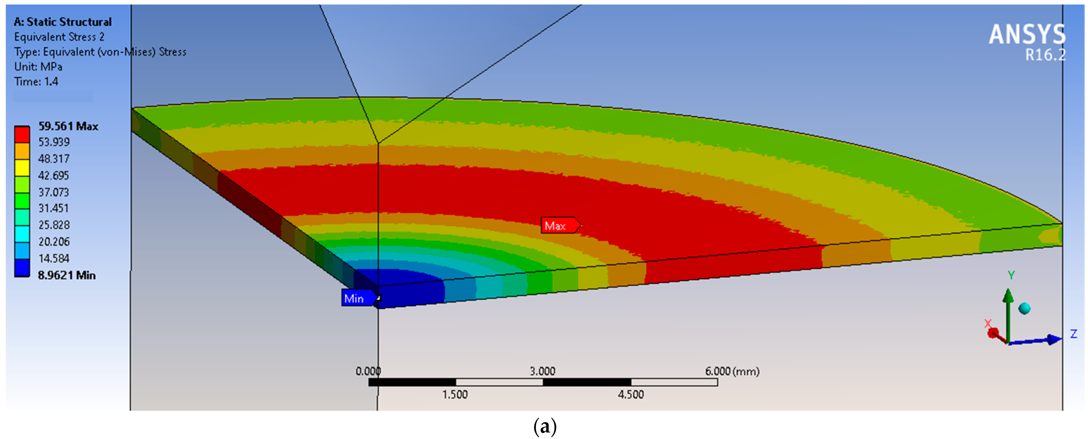
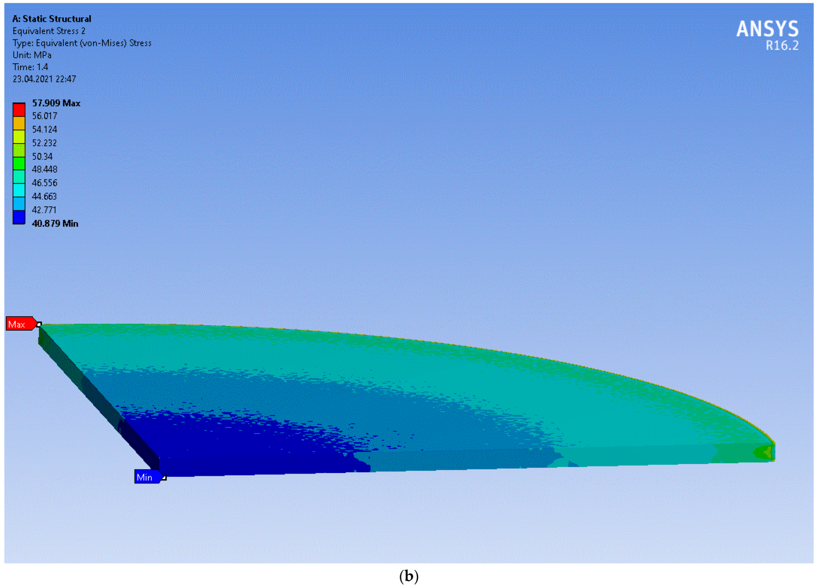
2.2. Finite Element Analysis, Boundary Conditions

Considerable research has been performed to investigate the stress-strain distribution in oxide coating and substrate interface to develop six finite element models using the ANSYS R16.2 programme, (Ansys Inc., Canonsburg, PA, USA). The axisymmetric models included two identical cylindrical halves, bonded together with a ceramic coating.
In order to facilitate calculations, the adhesive layer (glue) was excluded from the models, and the primary objective of this study was to estimate the level of uniformity in the interface stress distribution. It was therefore possible to simplify the finite element models of the specimens.
The following boundary conditions and assumptions were made for the finite-element models:
  • The contact between the substrate and coating was assumed as a rigid connection with a restriction on all degrees of freedom
  • Axial symmetry was provided by a cyclic region in the form of a 1/4 model by imposing boundary conditions to the symmetry regions along the XOY and YOZ planes
  • The material of the substrate and oxide coating possessed only elastic strain.
The finite element grid near the coating-substrate interface was more refined than in other areas of the model—approximately 0.1 mm (Figure 4). The results of a finite element analysis (FEA) of the models were compared with each other and with the results of the bond strength tests. The finite element models were loaded with a tensile load of F = 14,000 N to the threaded hole, as shown in Figure 4. The mechanical properties of the Al2O3 coating and substrate were taken from the material library of the ANSYS R16.2 programme.
Previous tests [31,32,33] revealed very similar mechanical and physical properties for the MgAl2O4, Al2O3 oxide coatings, which made it possible to perform FEA only for the Al2O3 coating.

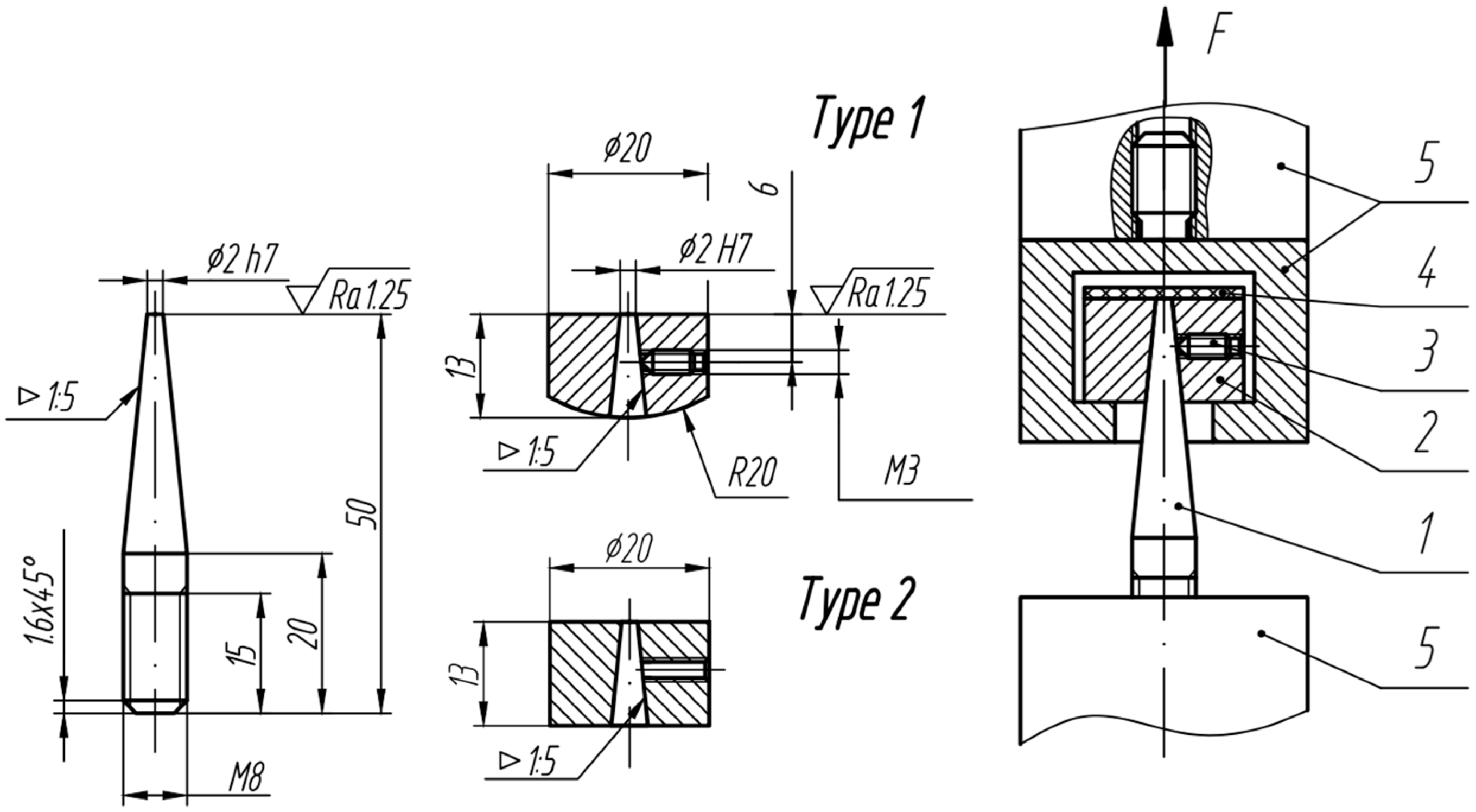
2.3. Tensile Adhesion Strength Testing

In this investigation, the test method of estimation tensile adhesion strength was based on the ASTM C633-13 (2021), GOST 9.304-87 [6,9] standards. Six specimens (standard and elongated) were bonded to the same uncoated specimens (counterparts) using a single-part epoxy resin Permobond ES 550 (maximum tensile strength σ ten = 60 ± 3 GPa, maximum shear strength τ sh = 41 ± 2 GPa by T = 20 °C). The alignment of the specimens was provided by centring bushings. The coatings produced were compared in terms of phase composition and microstructure, and the bond strength was also analysed at a temperature of T = 20 °C.
After thermal curing and cooling, the specimens were loaded with axial breaking force until debonding occurred at a traverse speed of 0.5 mm/min in the IR5143-200-11 tensile testing machine (JSC “Tochpribor”, Ivanovo, Russia [34]). The tensile adhesion strength of σ ten was calculated as the ratio between ultimate tensile force F divided by cross-sectional area A ( A = 491 mm2 for all testing results). Three identical tests were performed under the same conditions for each type of cylindrical specimen, using the MgAl2O4, Al2O3 plasma spray coating.

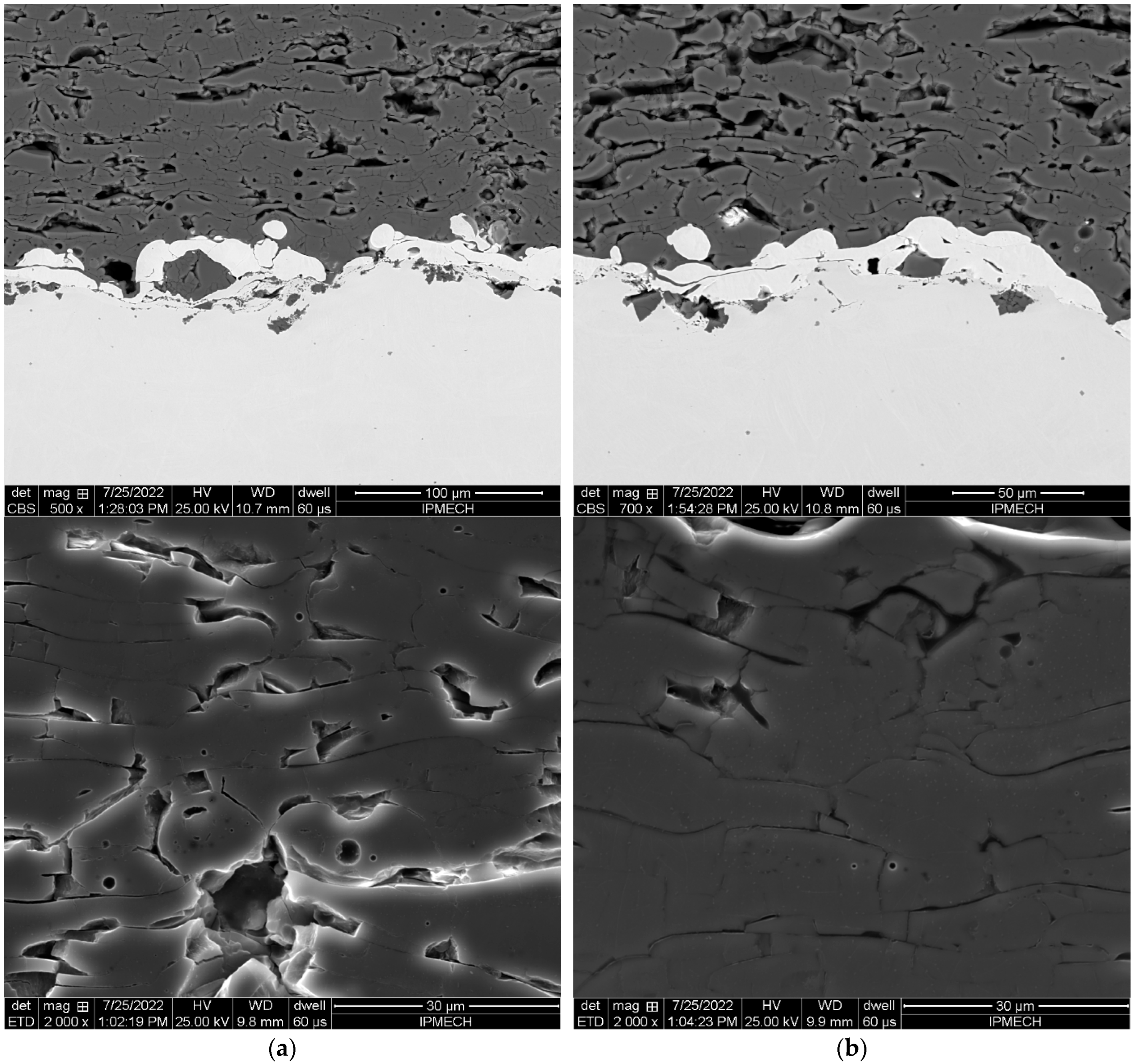
3. Results and Discussion

3.1. Results of Tensile Bond Strength of Standard and Elongated Specimens

Verification of the FEA data was performed by comparing them with the summary results of the tensile adhesion testing. The bond strengths of the APS ceramic coatings—MgAl2O4, Al2O3 for both standard and elongated specimens—are shown in Table 2. Before testing the tensile strength of the coating thickness, the h c and roughness Ra were estimated (Table 2). In the present investigation, the adhesive failure mode occurred at the bond coating-substrate interface [30] for all of the tensile tests of the MgAl2O4, Al2O3 coatings, without the visible penetration of epoxy resin into the coating-substrate interface. The trend of decreased adhesion strength for elongated specimens correlated well with the FEA results.
The results of the tensile adhesion strength tests showed a low level of bond strength for applied APS technology for MgAl2O4, Al2O3 coatings [3,10,22,24]. This may be related to the spraying equipment used, the construction of the plasma torch, the residual stress distribution, the fatigue crack propagation, the pore size and distribution [35], or the rate of particle velocity and temperature.
The high level of stress discontinuity at the coating-substrate interface might help explain the increased value of the adhesion strength (Table 2). As the surface morphology images in Figure 5 show, the low level of bond strength conforms well to the results of the metallographic analysis of the scanning electron microscope (SEM) images of the cross sections and surface morphologies of the coatings (large, moulded agglomerates, a large number of pores and other defects).

3.2. Assessment of Stress Distribution during Tensile Testing

The equivalent stress distribution and total strain showed in the three standard and three elongated specimens are shown in Figure 6, Figure 7 and Figure 8. A calculation of the stress distribution at the interface of three standard specimens showed a high level of non-uniformity over the debonding area. For example, the maximum value of equivalent stress came at the outer edge of the ASTM C633-13 (2021) standard specimen (type 3, Figure 2)— σ eq max = 71.5 MPa and the minimum value occurs at the centre— σ eq min = 14.5 MPa (Figure 8). The international standards procedure assumes that the stress is uniform based on testing a cylindrical specimen. The most uneven distribution of the equivalent stress was found at the interface of the GOST 9.304-87 standard specimen (type 1, Figure 2)—the maximum σ eq max = 59.6 MPa occurs between the centre and the outer edge of the specimen, while the minimum σ eq min = 9 MPa occurs at the centre of the specimen (Figure 6). The maximum value of the equivalent stress can therefore be taken as the average equivalent of the interface for the standard specimen type 1— σ eq max =   σ eq ¯ .
The average equivalent stress σ eq ¯ = 43 MPa (Figure 8) showed by FEA is 155% higher than the average tensile adhesion strength σ ten = 27.8 ± 0.6 MPa for Al2O4 (type 3, see Table 2) assumed by the ASTM C633-13 (2021) procedure.
The level of non-uniformity stress distribution in the test specimen was estimated using the following equation:
β   = σ eq max σ eq min ,
The non-uniform stress distribution will lead to the misinterpretation of the adhesion tensile testing results [14]. Significant excess of peak stress values at the outer edge, compared with average stress distribution, means that the inherent determination of high or low values of adhesion strength can be assumed by the ASTM C633-13 (2021), GOST 9.304-87 test procedure. The result implies that the bond strength depends not only on the geometry of a specimen [14,16], but also on the degree of plasticity and brittleness of the coating (brittle or ductile fracture).
The main reasons for the appearance of significant non-uniform interface stress distribution should also be mentioned. These are the appearance of additional shear stress at the outer edge of the coating (the Edge effect), and the decrease in the stiffness of the specimen due to the close proximity of the threaded hole in relation to the detachment surface of the coating.
The impact of the Edge effect can be minimized by increasing the diameter of the cylindrical specimen, up to d spec = 40–60 mm, as well as the length of a cylindrical specimen. The distance from the threaded closed holes to the plane face of a cylindrical specimen with a diameter of d spec = 25/25.4 mm should be enough to minimise the stiffness reduction. Applying elongated specimens with lengths of h spec = 38–50 mm and more [9] will lead to more uniform stress distribution.
The finite element analysis and laboratory testing of the elongated cylindrical specimens with a diameter of d spec = 25/25.4 mm confirmed that the results of estimating bond strength using a standard cylindrical specimen assumed by ASTM C633-13 (2021), GOST 9.304-87 can be significantly higher than the actual tensile adhesion strength [2]. With the exception of the GOST 9.304-87 standard specimen, the equivalent stress peaks were not identified at the centre of the specimens, but rather, at the outer edge in all models.

4. Conclusions

According to the results of this scientific study and the analysis of the existing literature, we were able to make three conclusions. Firstly, the significant peak stress at the outer edge of the specimen, compared to the average stress calculated by tensile testing, implies that the bond strength should be estimated using elongated specimens, according to the ASTM C633-13 (2021), GOST 9.304-87 test procedure. Secondly, compared to conventional tests (EN ISO 14916:2017, ASTM C633-13 (2021), GOST 9.304-87), the accuracy of tensile bond strength estimation may be higher when the new geometry of a cylindrical specimen is applied. Thirdly, to provide a more accurate method, researchers should carry out finite element analysis and an epoxy tensile adhesion test using elongated cylindrical specimens using different diameters, d spec = 20–60 mm (using the procedure defined in ASTM C633-13 (2021), GOST 9.304-87).

Author Contributions

A.Z. developed and planned the concept and methodology for conducting and reporting this science work. A.L., D.D. and A.Z. carried out the simulations of stress-strain stated at the coating-substrate interface and analysed the data on the tensile tests. D.D. undertook the spraying of coatings on specimens. A.Z. wrote the draft document. Y.A. organised SEM analysis and contributed to the discussion and interpretation of the results. All authors have read and agreed to the published version of the manuscript.

Funding

The study was carried out with the financial support of the Ministry of Science and Higher Education of the Russian Federation within the framework of the state task theme no. AAAAA12-2110800012-0.

Institutional Review Board Statement

Not applicable.

Informed Consent Statement

Not applicable.

Data Availability Statement

Not applicable.

Conflicts of Interest

The authors declare no conflict of interest.

References

  1. Niemi, K.; Hakalahti, J.; Hyvärinen, L.; Laurila, J.; Vuoristo, P.; Berger, L.-M.; Toma, F.-L.; Shakhverdova, I. Influence of chromia alloying on the characteristics of APS and HVOF sprayed alumina coatings. In Proceedings of The ITSC 2011, International Thermal Spray Conference & Exposition, Düsseldorf, Germany, 27−29 September 2011; Volume 276. [Google Scholar]
  2. Sang, P.; Chen, L.-Y.; Zhao, C.; Wang, Z.-X.; Wang, H.; Lu, S.; Song, D.; Xu, J.-H.; Zhang, L.-C. Particle size-dependent microstructure, hardness and electrochemical corrosion behavior of atmospheric plasma sprayed NiCrBSi coatings. Metals 2019, 9, 1342. [Google Scholar] [CrossRef] [Green Version]
  3. Junge, P.; Rupprecht, C.; Greinacher, M.; Kober, D.; Stargardt, P. Thermally Sprayed Al2O3 Ceramic Coatin–s for Electrical Insulation Applications. In Proceedings of The ITSC, International Thermal Spray Conference, Vienna, Austria, 4−6 May 2022; pp. 72–81. [Google Scholar]
  4. Popov, A.I.; Lushchik, A.; Shablonin, E.; Vasil’chenko, E.; Kotomin, E.A.; Moskina, A.M.; Kuzovkov, V.N. Comparison of the F-type center thermal annealing in heavy-ion and neutron irradiated Al2O3 single crystals. Nucl. Instrum. Methods Phys. Res. Sect. B Beam Interact. Mater. At. 2018, 433, 93–97. [Google Scholar] [CrossRef]
  5. Lushchik, A.; Feldbach, E.; Kotomin, E.A.; Kudryavtseva, I.; Kuzovkov, V.N.; Popov, A.I.; Seeman, V.; Shablonin, E. Distinctive features of diffusion-controlled radiation defect recombination in stoichiometric magnesium aluminate spinel single crystals and transparent polycrystalline ceramics. Sci. Rep. 2020, 10, 7810. [Google Scholar] [CrossRef]
  6. ASTM C633-13; Standard Test Method for Adhesion or Cohesion Strength of Thermal Spray Coatings. ASTM International: West Conshohocken, PA, USA, 2021. Available online: https://www.astm.org/c0633-13r21.html (accessed on 7 November 2022).
  7. EN ISO 14916; Thermal spraying—Determination of Tensile Adhesive Strength. ISO: Geneva, Switzerland, 2017. Available online: https://www.iso.org/standard/60995.html (accessed on 7 November 2022).
  8. JIS H 8666; Test Methods for Ceramic Sprayed Coatings. Japanese Standards Association: Tokyo, Japan, 1994. Available online: https://jis.eomec.com/abolished/jish86661994?abolishedid=10886661994#gsc.tab=0 (accessed on 7 November 2022).
  9. GOST 9.304-87; Unified System of Corrosion and Ageing Protection. Thermal Sprayed Coatings. General Requirements and Methods of Control. GOST—USSR Ministry of Chemical and Petroleum Engineering: Moscow, Russia, 1987. Available online: https://docs.cntd.ru/document/1200014731 (accessed on 7 November 2022).
  10. Hadad, M.; Marot, G.; Démarécaux, P.; Chicot, D.; Lesage, J.; Rohr, L.; Siegmann, S. Adhesion tests for thermal spray coatings: Correlation of bond strength and interfacial toughness. J. Surf. Eng. 2007, 23, 279–283. [Google Scholar] [CrossRef]
  11. Vencl, A.; Arostegui, S.; Favaro, G.; Zivic, F.; Mrdak, M.; Mitrović, S.; Popovic, V. Evaluation of adhesion/cohesion bond strength of the thick plasma spray coatings by scratch testing on coatings cross-sections. Tribol. Int. 2011, 44, 1281–1288. [Google Scholar] [CrossRef]
  12. Chen, Z.; Zhou, K.; Lu, X.; Yee, C.L. A review of the mechanical methods for evaluating coating adhesion. Acta Mech. 2014, 255, 431–452. [Google Scholar] [CrossRef]
  13. Lorenzo-Bañuelos, M.; Díaz, A.; Rodríguez, D.; Cuesta, I.I.; Fernández, A.; Alegre, J.M. Influence of Atmospheric Plasma Spray Parameters (APS) on the Mechanical Properties of Ni-Al Coatings on Aluminum Alloy Substrate. Metals 2021, 11, 612. [Google Scholar] [CrossRef]
  14. Han, W.; Rybicki, E.F.; Shadley, J.R. An improved specimen geometry for ASTM C633-79 to estimate bond strengths of thermal spray coatings. J. Therm. Spray Technol. 1993, 2, 145–150. [Google Scholar] [CrossRef]
  15. Lindner, T.; Saborowski, E.; Scholze, M.; Zillmann, B.; Lampke, T. Thermal Spray Coatings as an Adhesion Promoter in Metal/FRP Joints. Metals 2018, 8, 769. [Google Scholar] [CrossRef] [Green Version]
  16. Lyphout, C.; Nylen, P.; Östergren, L.G. Adhesion Strength of HVOF Sprayed IN718 Coatings. J. Therm. Spray Technol. 2011, 21, 145–150. [Google Scholar] [CrossRef]
  17. Stokes, J.; Looney, L. FEA of residual stress during HVOF thermal spraying. J. Mat. Eng. Perf. 2009, 18, 21–25. [Google Scholar] [CrossRef]
  18. Boruah, D.; Robinson, B.; London, T.; Wu, H.; de Villiers-Lovelock, H.; McNutt, P.; Doré, M.; Zhang, X. Experimental evaluation of interfacial adhesion strength of cold sprayed Ti-6Al-4V thick coatings using an adhesive-free test method. Surf. Coat. Technol. 2020, 381, 125–130. [Google Scholar] [CrossRef]
  19. Marot, G.; Démarécaux, P.; Lesage, J.; Hadad, M.; Siegmann, S.T.; Staia, M.H. The interfacial indentation test to determine adhesion and residual stresses in NiCr VPS coatings. Surf. Coat. Technol. 2018, 202, 4411–4416. [Google Scholar] [CrossRef]
  20. Ang, A.S.M.; Sanpo, N.; Sesso, L.; Kim, S.Y.; Berndt, C.C. Thermal Spray Maps: Material Genomics of Processing Technologies. J. Therm. Spray Technol. 2013, 22, 1170–1183. [Google Scholar] [CrossRef]
  21. Kiilakoski, J.; Trache, R.; Björklund, S.; Joshi, S.; Vuoristo, P. Process parameter impact on suspension-HVOF-sprayed Cr2O3 coatings. J. Therm. Spray Technol. 2019, 28, 1933–1944. [Google Scholar] [CrossRef] [Green Version]
  22. Yilmaz, Ş. An evaluation of plasma-sprayed coatings based on Al2O3 and Al2O3–13 wt.% TiO2 with bond coat on pure titanium substrate. J. Therm. Spray Technol. 2009, 35, 2017–2022. [Google Scholar]
  23. Winnicki, M. Advanced functional metal-ceramic and ceramic coatings deposited by low-pressure cold spraying: A review. Coatings 2021, 11, 1044. [Google Scholar] [CrossRef]
  24. Toma, F.-L.; Berger, L.-M.; Scheitz, S.; Langner, S.; Rödel, C.; Potthoff, A.; Sauchuk, V.; Kusnezoff, M. Comparison of the microstructural characteristics and electrical properties of thermally sprayed Al2O3 coatings from aqueous suspensions and feedstock powders. J. Therm. Spray Technol. 2012, 21, 480–488. [Google Scholar] [CrossRef] [Green Version]
  25. Hadad, M.; Marot, G.; Démarécaux, P.; Lesage, J.; Michler, J.; Siegmann, S.T. Adhesion tests tor thermal spray coatings: Application range of tensile, shear and interfacial indentation methods. In Proceedings of The ITSC 2005: Thermal Spray Connects: Explore Its Surfacing Potential (DVS-ASM), Basel, Switzerland, 2–4 May 2005; pp. 759–764. [Google Scholar]
  26. Yamazaki, Y.; Arai, M.; Miyashita, Y.; Waki, H.; Suzuki, M. Determination of interfacial fracture toughness of thermal spray coatings by indentation. J. Therm. Spray Technol. 2013, 22, 1358–1365. [Google Scholar] [CrossRef]
  27. Mueller, E. Stress peening—A sophisticated way of normal shot peening. J. Mater. Sci. Eng. 2019, A9, 56–63. [Google Scholar]
  28. Liu, Y.; Fu, S.; Wang, Z.; Yan, X.; Xi, N.; Wu, Y.; Chen, H. Tensile properties, shear strength calculation and cracking behavior of bulk composite comprised of thick HVOF sprayed coating and steel substrate. Surface and Coating Technol. 2019, 374, 807–814. [Google Scholar] [CrossRef]
  29. Public Joint Stock Company. Electromekhanika. Available online: http://www.el-mech.ru/products/pokryt/pokryt_67.html (accessed on 7 November 2022).
  30. Zaytsev, A.N.; Yagopol’skiy, A.G.; Aleksandrova, Y.P. Assessing the impact of the structure and chemical composition of plasma-sprayed coatings on their adhesion and tribological properties. BMSTU J. Mech. Eng. 2018, 5, 48–59. [Google Scholar]
  31. Toma, F.-L.; Scheitz, S.; Berger, L.-M.; Sauchuk, V.; Kusnezoff, M.; Thiele, S.V. Comparative study of the electrical properties and characteristics of thermally sprayed alumina and spinel coatings. J. Therm. Spray Technol. 2011, 20, 195–204. [Google Scholar] [CrossRef]
  32. Zaytzev, A.N.; Lukianova, A.N.; Demoretsky, D.A. Assessment of Shear Bond Strength of Thermal Spray Coatings by Applying Prismatic Samples. Solid State Phenom. 2022, 337, 35–41. [Google Scholar] [CrossRef]
  33. Pogrebnjak, A.D.; Tyurin, Y.N. Modification of material properties and coating deposition using plasma jets. UFN 2005, 175, 515–544. [Google Scholar] [CrossRef]
  34. Public Joint Stock Company. Tochpribor. Available online: https://www.tochpribor-kb.ru (accessed on 7 November 2022).
  35. Siao, M.A.A.; Berndt, C.C. A review of testing methods for thermal spray coatings. Int. Mat. Rev. 2014, 59, 179–223. [Google Scholar]
Figure 1. A conical pin specimen and self-aligned test fixture for tensile adhesion test: (1) Conical pin; (2) Matrix; (3) Centring screw; (4) Coating; (5) Equipment for tensile testing machine: F—ultimate tensile force.
Ceramics 05 00088 g001
Figure 2. Six types of cylindrical specimens used to evaluate the bond strength of the thermal spray coating.
Ceramics 05 00088 g002
Figure 3. The geometry of a cylindrical specimen (type 2) assembled by tensile force F = 14,000 N: (1) Specimen with coating; (2) Epoxy; (3) Specimen without coating; (4,5) Equipment for tensile testing machine; (6) Bushing.
Ceramics 05 00088 g003
Figure 4. The axisymmetric finite element model for the standard specimen (type 1): (a) the finite element of two identical cylindrical halves bonded together with ceramic coating, GOST 9.304-87; (b) the 3-D finite element model grid.
Ceramics 05 00088 g004
Figure 5. Cross-section SEM images of microstructures of the coating: (a) Al2O3; (b) MgAl2O4. For spray parameters, refer to Table 2.
Ceramics 05 00088 g005
Figure 6. Equivalent stress distribution at the debonding area of the Al2O3 coating with a tensile force of F = 14,000 N: (a) GOST 9.304-87 standard specimen, type 1; (b) Elongated specimen, type 4. For geometric parameters, see Figure 2.
Ceramics 05 00088 g006aCeramics 05 00088 g006b
Figure 7. The equivalent stress distribution and total strain at the debonding area of the coating Al2O3 with tensile force F = 14,000 N: (a) Modified specimen, type 2; (b) Elongated specimen, type 5. For geometric parameters, refer to Figure 2.
Ceramics 05 00088 g007
Figure 8. Equivalent stress distribution and total strain at the debonding area of the Al2O3 coating with a tensile force of F = 14,000 N: (a) ASTM C633-79 (2021) standard specimen, type 3; (b) Elongated specimen, type 6. For geometric parameters, see Figure 2.
Ceramics 05 00088 g008
Table 1. Plasma spraying operating parameters.
ParametersMgAl2O4, CoatingAl2O3, CoatingNiAl, Bond Coat
Current (A) × voltage [V] = power [kW]330 × 50 = 16.50320 × 50 = 16.00330 × 48 = 15.84
Spray distance, [mm]10590
Feed powder, [g/min]15–1830
Velocity of travel plasma torch, [s/min]28001600
Carrier gas type and flow rates, [L/min]Ar: 25–30; N2: 2.0–2.4Ar: 20–25; N2: 1.5–2.0
Transporting gas type and flow rate, [L/min]Ar: 2.5−3.0
Number of passes9–101–2
Table 2. Summary results of tensile bond strength measurements for APS—MgAl2O4, Al2O3 and finite element surface stresses on standard and elongated specimens.
Type of Specimen/Test MethodType of CoatingThickness
h c [μm]
Roughness R a [μm]Tensile Bond Strength σ ten ¯ ± δ [MPa]Relative Error of Tensile Bond Strength [%]Finite Element Average Equivalent Stress σ eq ¯ [MPa] β
Type 1, standard/GOST 9.304-87 [9]Al2O3_APS420 ± 3538 ± 1030.1 ± 1.65606.7
MgAl2O4_APS406 ± 2733 ± 628.8 ± 1.97--
Type 4, elongated/GOST 9.304-87 [9]Al2O3_APS484 ± 2129 ± 425.0 ± 2.610451.4
MgAl2O4_APS446 ± 4548 ± 522.0 ± 4.319--
Type 2, modified/an in-house test methodAl2O3_APS424 ± 3833 ± 823.2 ± 3.214453.1
MgAl2O4_APS484 ± 1831 ± 426.4 ± 1.66--
Type 5, elongated/an in-house test methodAl2O3_APS426 ± 3631 ± 619.4 ± 0.52441.8
MgAl2O4_APS440 ± 2930 ± 220.8 ± 2.010--
Type 3, standard/ASTM C633-13 (2021) [6]Al2O3_APS460 ± 3237 ± 827.8 ± 0.62434.9
MgAl2O4_APS430 ± 3038 ± 425.1 ± 3.213--
Type 6, elongated/ASTM C633-13 (2021) [6]Al2O3_APS472 ± 1233 ± 320.7 ± 1.78441.7
MgAl2O4_APS450 ± 3137 ± 318.4 ± 1.58--
Publisher’s Note: MDPI stays neutral with regard to jurisdictional claims in published maps and institutional affiliations.

