Article

Comparative Properties of Porous Phyllosilicate-Based Ceramics Shaped by Freeze-Tape Casting

by
Kassoum Barry
1,2,
Gisèle Laure Lecomte-Nana
1,*,
Mohamed Seynou
2,
Michael Faucher
1,
Philippe Blanchart
1 and
Claire Peyratout
1
1
IRCER (Institut de Recherche sur les Céramiques), Université de Limoges, 12 Rue Atlantis, 87068 Limoges, France
2
LC2M (Laboratoire de Chimie Moléculaire et des Matériaux), Unité de Formation et de Recherche en Sciences Exactes et Appliquées (UFR-SEA), Département de Chimie, Université Joseph KI-ZERBO, Avenue Charles De Gaulles, Ouagadougou 7021, Burkina Faso
*
Author to whom correspondence should be addressed.
Ceramics 2022, 5(1), 75-96; https://doi.org/10.3390/ceramics5010007
Submission received: 31 December 2021 / Revised: 24 January 2022 / Accepted: 28 January 2022 / Published: 31 January 2022
(This article belongs to the Topic Industrial Application of Clays and Clay Minerals)

Abstract

:
Porous phyllosilicate-based ceramics were manufactured by freeze-tape casting from clays of different particle size and morphology in order to characterize their microstructure and stress to rupture changes before and after firing. Three raw clays were selected: HCR (77% Halloysite–10Å), KORS (29% kaolinite), and KCR kaolin (98% kaolinite). These clays exhibited a monomodal distribution and were used to prepare four slurries, three with each clay material and one consisting of a mixture of KCR and HCR labeled KHCR. After shaping by freeze-tape casting, the porosity and stress to rupture obtained by a biaxial flexural test were collected for disk-like samples after drying and sintering at 1200 °C. Results showed that KCR ceramic materials had the highest biaxial bending strength (70 ± 1.1 MPa) and those from KORS had the highest porosity value (80 ± 1%). SEM observation revealed a difference in microstructure and texture for the manufactured porous ceramic materials. In the KCR ceramic disks, the flattened pores appeared more textured, and the primary mullite crystallites formed a rigid skeleton within the amorphous phase. KORS ceramic materials showed a small quantity of secondary mullite needles which were randomly dispersed in a vitreous phase. The relatively important vitreous phase in the porous materials of HCR led to the bulk formation of small mullite particles. The biaxial flexural strength values were related to the presence of the mullite, as well as to the microstructure (volume, morphology, and size distribution of pores) after sintering.

1. Introduction

Since the early 1970s, porous ceramics have been studied for various applications such as energy, the environment [1,2,3,4,5,6], and building purposes [7,8]. Since the year 2000, research interest on the processing of porous ceramics has significantly increased thanks to the development of different technologies and methods, including soft chemistry, additive manufacturing, and spark plasma sintering [6,9]. In the field of water treatment, membrane technology (microfiltration, ultrafiltration, or nanofiltration) is considered an effective means of water purification [5,6,10] and in particular, ceramic membranes are widely studied owing to their excellent mechanical properties, thermal stability, high chemical resistance, and long life cycle [1,11]. These porous and textured ceramics can be produced by different methods, such as compaction [1,3], sol–gel [12], extrusion [13], hydrothermal synthesis [14], and gel casting [15]. Among these techniques, compaction is one of the most frequently employed methods for manufacturing porous ceramics [16,17]. Therefore, the incorporation of a pore-former or porogen agent into the starting mixture is required. The as-obtained ceramic products provide sufficient mechanical strength as well as a highly porous texture [18] and thus allows the filtration of pollutants contained in water with a high flow rate to produce drinking (tap) water [1,19,20,21].
The porous ceramics for water treatment are currently made by using silicates, and the range of porosity ranges from 40% to 80% depending on the target final properties [1,4,7,10,21,22]. With the current environmental and energy regulations regarding sustainability (availability, embodied CO2, reuse, etc.) issues, the need for eco-materials is gaining interest. Indeed, clays appear to be appropriate raw material resources for these applications. Clays are readily available raw materials, mainly constituted from clay minerals, that exhibit a layered structure and are classified as phyllosilicates [23,24,25]. In general, raw clays also include some secondary non-clay minerals such as quartz, mica, feldspar, iron oxides, and titanium oxides. The relative amount of these secondary phases will have a significant effect on the sintering behavior and the final properties (porosity, color, stress to rupture, etc.) of related ceramic products [12,26,27]. Regarding clay minerals, two main families are identified according to the piling up of silica-rich tetrahedral layers and alumina (or magnesia)-rich octahedral layers to form the unit sheet. The 1:1 or Te-Oc phyllosilicates unit sheet originates from the stacking of one octahedral and one tetrahedral layer, and includes minerals such as kaolinite, halloysite, and lizardite. In the case of 2:1 or Te-Oc-Te phyllosilicates, the unit sheet results from the piling-up of one octahedral layer sandwiched between two tetrahedral layers; this includes, for example, pyrophyllite, chlorites, talc, smectites, and illites. Indeed, their layer structure can be profitable to manufacture textured and/or porous silicate ceramics.
Previous works showed that the technique of tape casting allows for the production of textured and porous ceramics, which can have potential applications in water filtration [28,29]. Jin et al. [29] used the tape casting process to obtain ceramic materials with an interconnected pore network and an asymmetric structure. In particular, freeze-tape casting allows for the production of ceramics with a singular and highly porous texture. Rachadel P. L. et al. [28] used this process to produce ceramic-based perovskite supports with an interconnected and lamellar pore network. Freeze-tape casting technology is not yet well-developed, so we mounted a homemade setup and attempted to produce low-cost porous ceramics using phyllosilicate-rich materials (which are easy to reuse and environmentally friendly). The aim of this work is to manufacture textured and porous ceramics based on natural clays rich in kaolinite or halloysite by the process of freeze-tape casting. Three types of clay with different particle sizes and fluxing oxide contents were used in this study in order to compare the microstructure and mechanical resistance changes of related tapes before and after consolidation at 1200 °C.

2. Materials and Methods

2.1. Raw Materials

In this study, three raw clay materials rich in kaolinite or halloysite, called KCR, HCR, and KORS, respectively, were used to manufacture the ceramic tapes. HCR (rich in halloysite) and KORS were natural ground clays from Cameroon and Burkina Faso, respectively. KCR was provided by Imerys society (Limoges, France). Dolaflux B11® (CERADEL, Limoges, France), PolyVinyl Alcohol 22000® (PVA 22000, VWR, Prolabo, Fontenay-sous-Bois, France) and PolyEthylene Glycol 300® (PEG 300, SIGMA ALDRICH, St. Quentin Fallavier, France) were used as dispersants of particles in distilled water, organic binder, and plasticizer, respectively.

2.2. Processing of the Porous Phyllosilicate-Based Ceramics

Prior to the shaping process, surfactants (dispersant, binder, and plasticizer) were introduced into the prepared slurries in order to improve the stability of the slurries, and the mechanical strength and flexibility to the green tapes regarding their handling.

2.2.1. Preparation of the Slurries

Four different slurries were prepared with regard to the raw clay material: three slurries containing KCR, KORS, and HCR, respectively; and a fourth slurry resulting from a mixture of 50 mass % each of KCR and HCR, identified as KHCR. For each slurry, the preparation includes the followings steps:
(i)
The clay powder was mixed with deionized water containing an appropriate amount of dispersant (0.2 wt.% regarding the clay content) to achieve a clay content within the slurry close to 62.5 wt.%. The dispersant introduction was important to ensure the homogeneity and stability of the particles in suspension. Indeed, the mixture was gently mixed on a roller-mixer for about 12 h to promote the dispersant adsorption onto the surface of particles.
(ii)
This step involved the grinding of the obtained slurry in a planetary mill with a rotational speed of 180 rpm for 6 h to obtain the adequate grain size distribution based on previous studies [23,24].
(iii)
After the first grinding step, 5 wt.% of binder (PVA 22,000) and 5 wt.% of plasticizer (PEG 300) were added to the slurry before achieving the second grinding step in the planetary mill with a rotational speed of 100 rpm for 16 h.
(iv)
Finally, the slurry was sieved to <125 μm to remove the residual agglomerates before the freeze-tape casting operation.

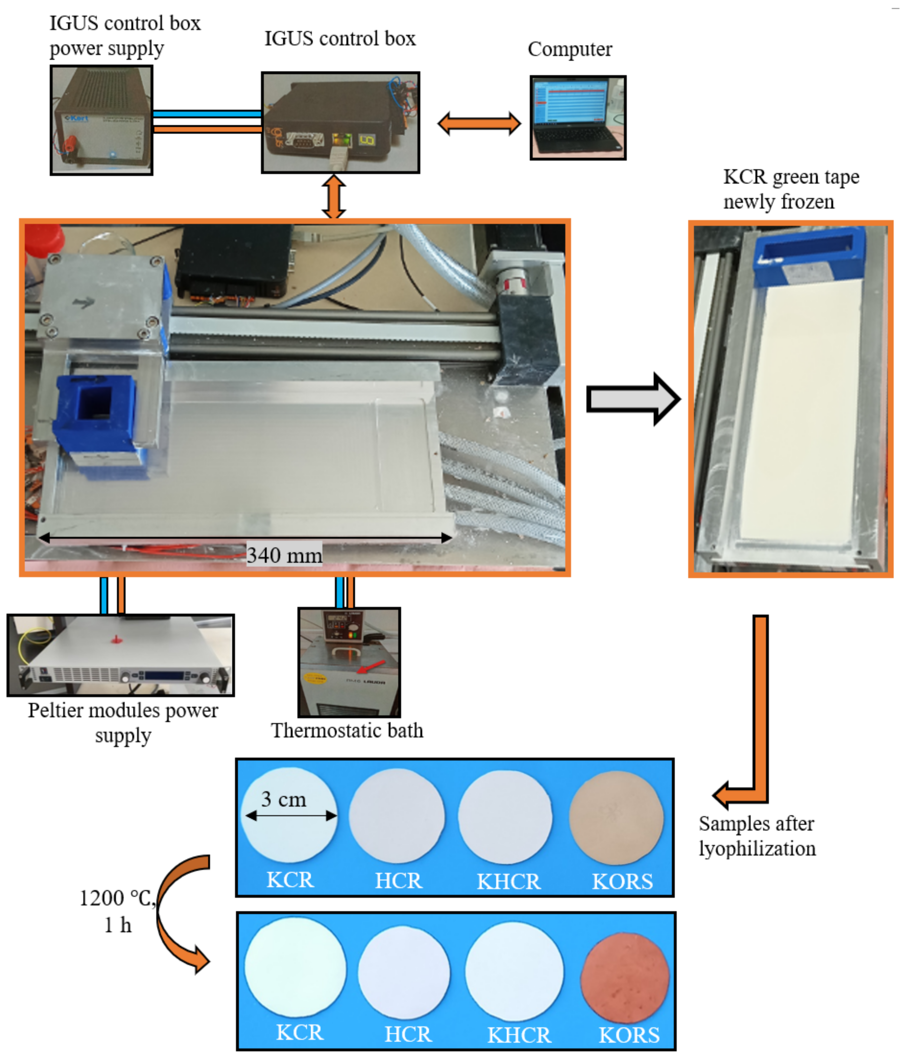
2.2.2. Shaping and Sintering of Phyllosilicate-Based Tapes

A homemade setup was mounted to realize the simultaneous casting and freezing of the slurries. This setup, illustrated in Figure 1, consisted of a container to ensure the regular and monitored pouring of the slurry; a horizontal copper support, which enables the fast and homogeneous repartition of the temperature; a thermocouple, in order to control the temperature close to the tape; two generators, to supply the appropriate power requested for the cooling of the Peltier cells embedded within the copper plate and the displacement of the container; and a computer connected to the device, for the monitoring of the casting speed and length. The thermostatic bath is useful in order to facilitate the cooling of the copper plate (regardless of the room temperature) at temperature lower than 10 °C before starting the freeze-tape casting operation. The gap between the blade of the container and the copper plate was fixed at 200 μm, while the casting shear rate was close to 50 s−1 (casting speed is 10 mm/min). After sieving the slurry, the tape was cast by introducing 10 mL of suspension into the reservoir. The casting was performed onto a polymeric (Mylar) film covering the copper plate maintained at –5 °C. Following the removal of the reservoir at the end of the casting, the cooling temperature was set to –15 °C. After 2 min of stabilization, the tapes were collected and stored in a freezer until their lyophilization (freeze-drying). The latter operation was conducted at –80 °C, under a pressure of 10−2 mbar for 7 h. At this stage, the disk-like samples of 30 mm in diameter were punched out from the dry tapes and submitted to physical and chemical characterizations (Figure 1). The heat treatment (at 1200 °C) applied to these samples (Figure 1) consisted of two main ramps: (1) a ramp of 1 °C/min from room temperature to 500 °C followed by 1 h soaking at 500 °C, and (2) a ramp of 3 °C/min up to 1200 °C, whereby a dwelling time of 1 h was applied before cooling to room temperature.

2.3. Characterization Techniques

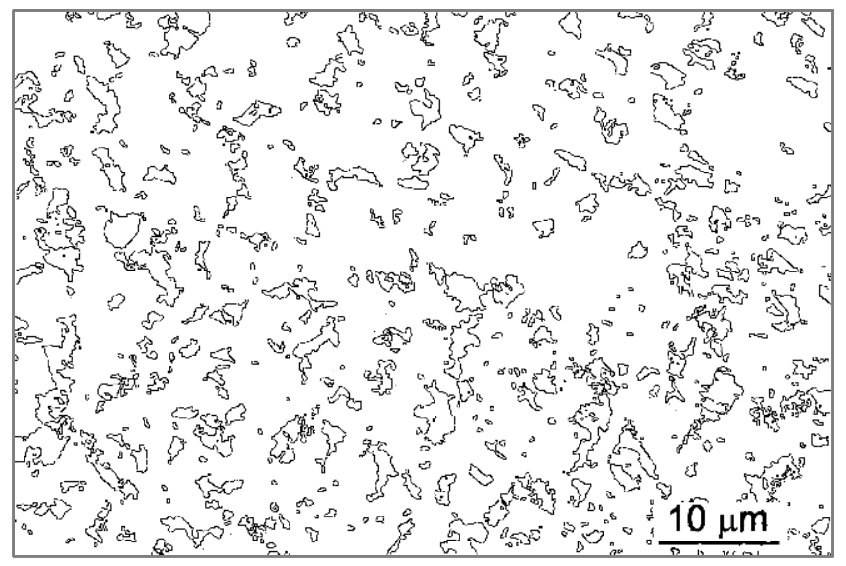
2.3.1. Morphological Analysis

The specific surface area was determined by the nitrogen gas adsorption (BET method), using an ASAP 2020 device (Micromeritics Instrument, Norcross, GA, USA). Previously, the samples were submitted to degassing at 250 °C for 4 h to reach a required pressure of 6.5 Pa. The density of clay powders was measured using an AccuPyc II 1340 Pycnometer (Micromeritics Instrument, Norcross, GA, USA) with a sample chamber volume of 1 cm3. The samples were previously dried at 105 °C for 24 h before each measurement.
The particle size distribution (PSD) of the casting suspensions and clays (KCR, HCR, and KORS) was determined using Laser Scattering equipment, Horiba LA-950 V2 (Kyoto, Japan). In this study, before each measurement 0.5 g of each type of clay was added to 10 mL of NaHMP solution (1 g/L). Moreover, all the suspensions were de-agglomerated under ultrasound (37 kHz) for 1 min. All the measurements were carried out at room temperature, and each sample was measured at least five times. PSD values listed in this paper are average values.

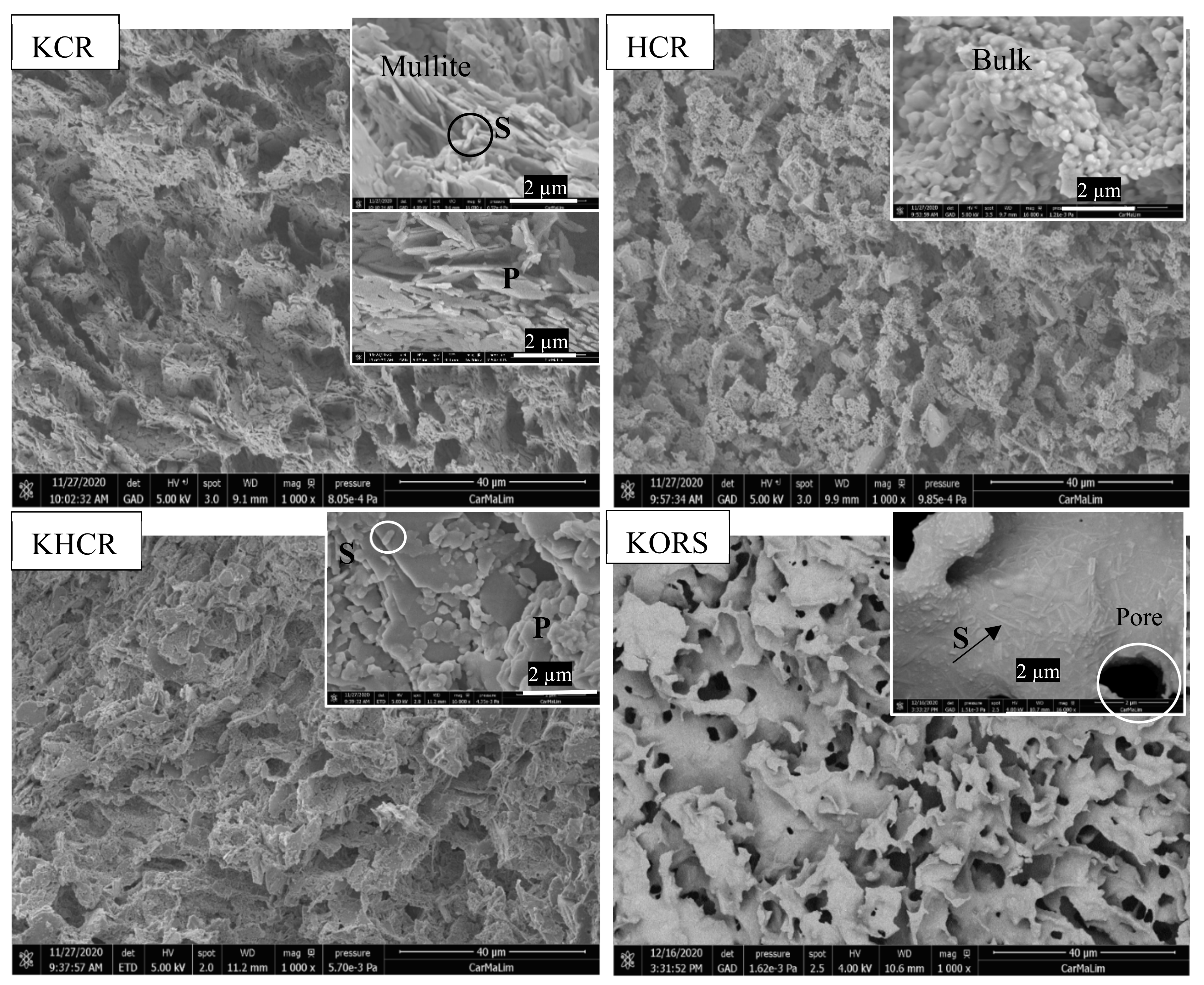
2.3.2. Microstructure

Scanning electron microscopy observations were performed using the FEI Quanta 450 FEG device (Thermo Fisher Scientific, Waltham, MA, USA). Bulk specimens were characterized (surfaces and sections of tapes before and after sintering). Before observation, bulk samples were coated using a 10 nm platinum layer in order to ensure sufficient electron conduction at external surfaces. Powder samples were observed after a previous dispersion in ethanol. A drop of each prepared suspension was placed onto a sample holder and then dried.
The porosity of ceramic materials (raw and sintered) was evaluated from the geometrical density ( ρ g e o m ) and the density ( ρ s ) measured by pycnometer. The geometrical density was measured on the disk specimens of known diameter and thickness. The porosity, p in vol. %, was calculated from the formula Equation (1) established from the standard ISO 10545-3:2018 [30].
p   % = 1 ρ g é om ρ s × 100
Images were preprocessed using Gimp software. We removed the noise and performed a grey-level threshold to obtain a binary image. Successive uses of dilatation erosion filters are able to reduce the interconnections between particles. The remaining spurious areas were also removed. It is followed by a segmentation with image J, for partitioning the image into separated regions [31,32]. The analyses of particles from binary images perform the counting of pixels inside closed areas. From the number of pixels, we obtained the distribution of the particles size.

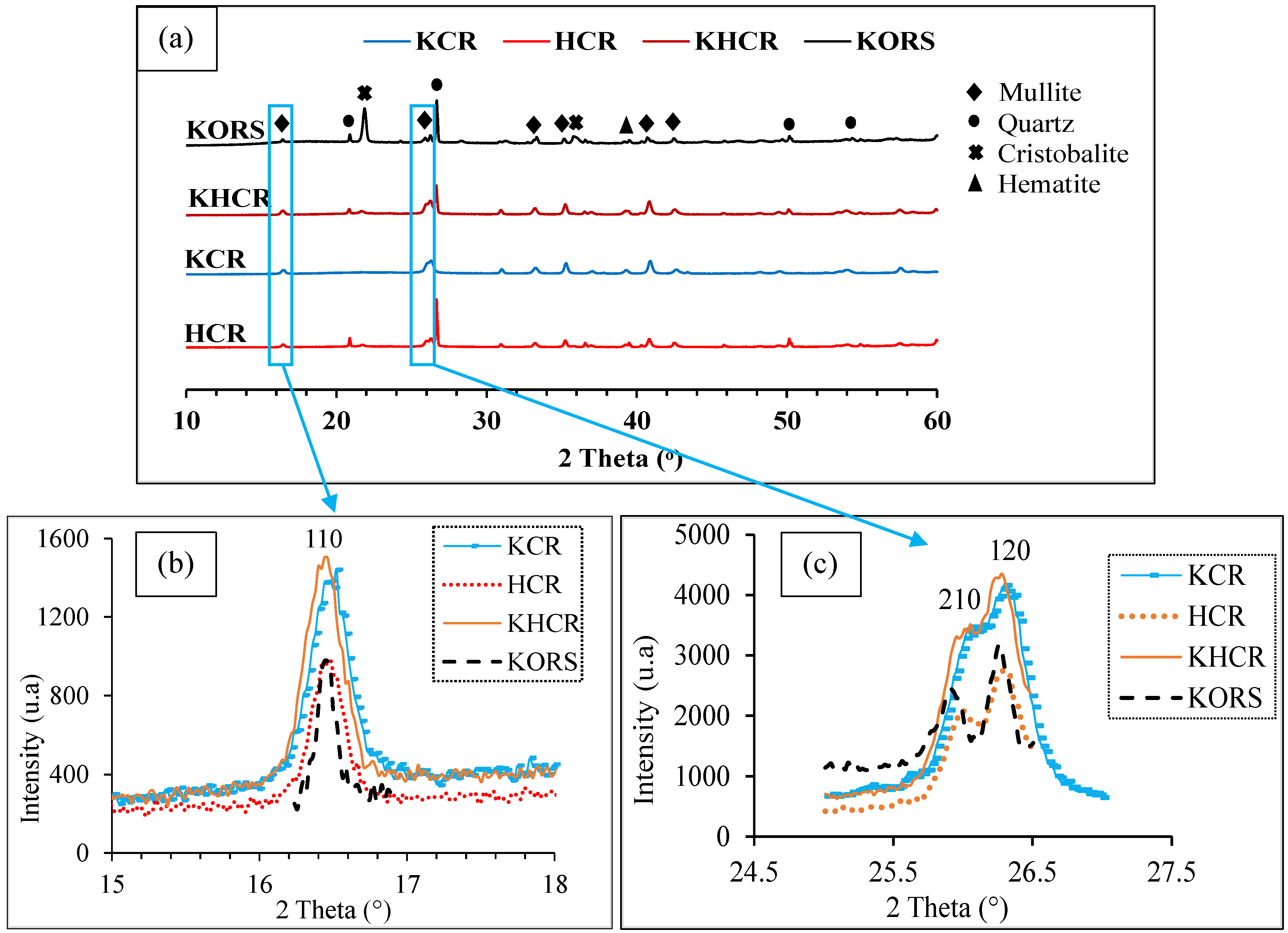
2.3.3. Chemical and Mineralogical Analyses

X-ray fluorescence analysis of the chemical composition of raw materials was measured with a Panalytical Zetium instrument (Malvern, Westborough, MA, USA) using a rhodium generator for X photon (60 kV, 50 mA). The measurements were performed for 40 min and using transparent disk samples (glass samples). These disk-like samples were obtained by mixing 1 g of raw material (KCR, HCR or KORS) with 10 g of lithium tetraborate (Li2B4O7) and by heating this mixture at 1050 °C within a platinum crucible. The semi-quantitative analysis allowed to identify chemical elements from oxygen to uranium.
The nature of the crystalline phases within the raw materials was examined through room temperature laboratory by X-ray diffraction (XRD) experiments using a D8 Advance DaVinci diffractometer (Bruker, Madison, WI, USA), operating in Bragg–Brentano geometry with CuKα1 radiation (λ = 0.1540598 nm). The operating voltage and current were maintained at 40 kV and 40 mA, respectively. The clay samples were placed into a classical transparent resin sample holder. The nature of the crystalline phases present in the raw materials was determined on powdered samples through qualitative analysis of XRD patterns (DIFFRAC.SUITE EVA software, Bruker Company, Madison, WI, USA) collected in a range of 2° < 2θ < 60° with a step of 0.02°, integration time of 0.54 s/step, and width of the slits of 15 mm. The DIFFRAC.SUITE EVA software was granted with the ICDD (PDF2, PDF4 plus), PDF4 AXIOM, and COD reference databases.
The crystalline phases within the manufactured materials were determined by X-ray diffraction (XRD) using the same device. The analyses were performed in the same conditions as for the raw materials; however, the shaped materials were glued in the specimen holder and adjusted to the same level.

2.3.4. Thermal Analyses

The differential thermal (DTA) and thermogravimetric (TG) analyses were carried out using a Setaram Labsys Evo device (SETARAM, City, France). Before DTA-TG analysis, the samples were dried at 105 °C for 24 h. During the measurement, specimens were introduced in a platinum crucible of 100 μL. A quantity of 45 mg of powder was analyzed for each sample. The analyses were conducted under synthetic air, from 30 °C to 1300 °C with heating and cooling rates of 5 °C/min, respectively.
The mass variations obtained by TG were correlated with the chemical composition and the qualitative XRD analysis to determine the number of the major phases in the starting clays.

2.3.5. Mechanical Resistance

The biaxial flexural tests were carried out with an “LLOYD Easy Test EZ 20” universal mechanical testing device, which was configured in compression and controlled by the NEXYGEN PLUS 3.0 software. The speed of elongation was set at 1 mm/min. The experimental procedure was performed according to standards in the case of a piston-ring configuration by ASTM F394-78 [33] and other previous works [34]. The calculations proposed by Kirsten and Woolley [35] allowed Glandus [36] to reach the formula Equation (3). The values of the tensile strength ( σ R ) of the ceramic disks before and after sintering were calculated using the formula Equation (2).
σ R = 3 P R 1 + υ 4 π e 2 1 + 2 × ln A B + 1 υ 1 + υ × 1 B 2 2 A 2 × A 2 B 2
A is the ring diameter (22 mm), B is the piston diameter (4.4 mm), e is the specimen (disc) thickness, PR (N) is the maximum load applied before breaking, and υ is the Poisson’s ratio (0.25).

3. Results

3.1. Powder Characterization

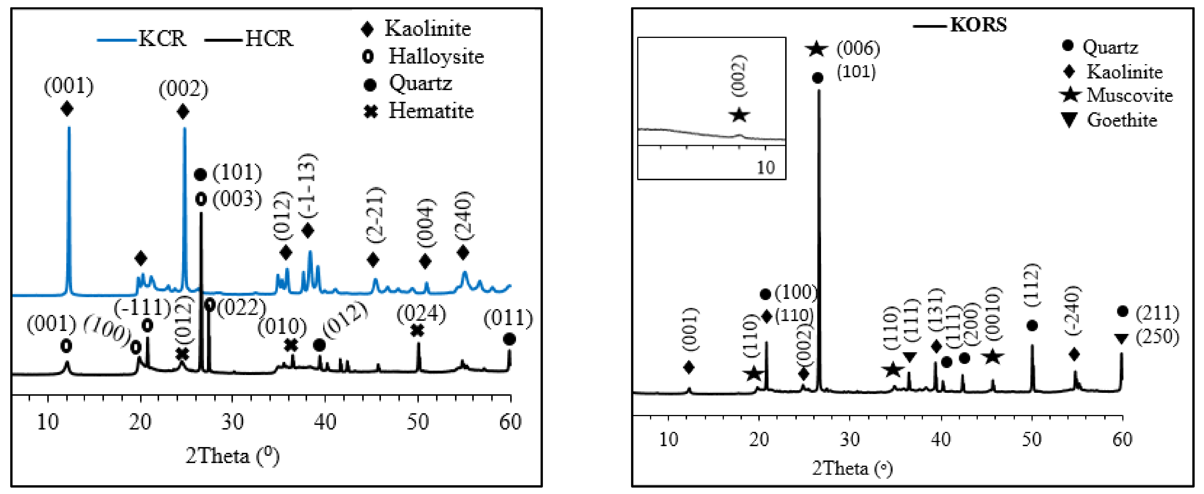
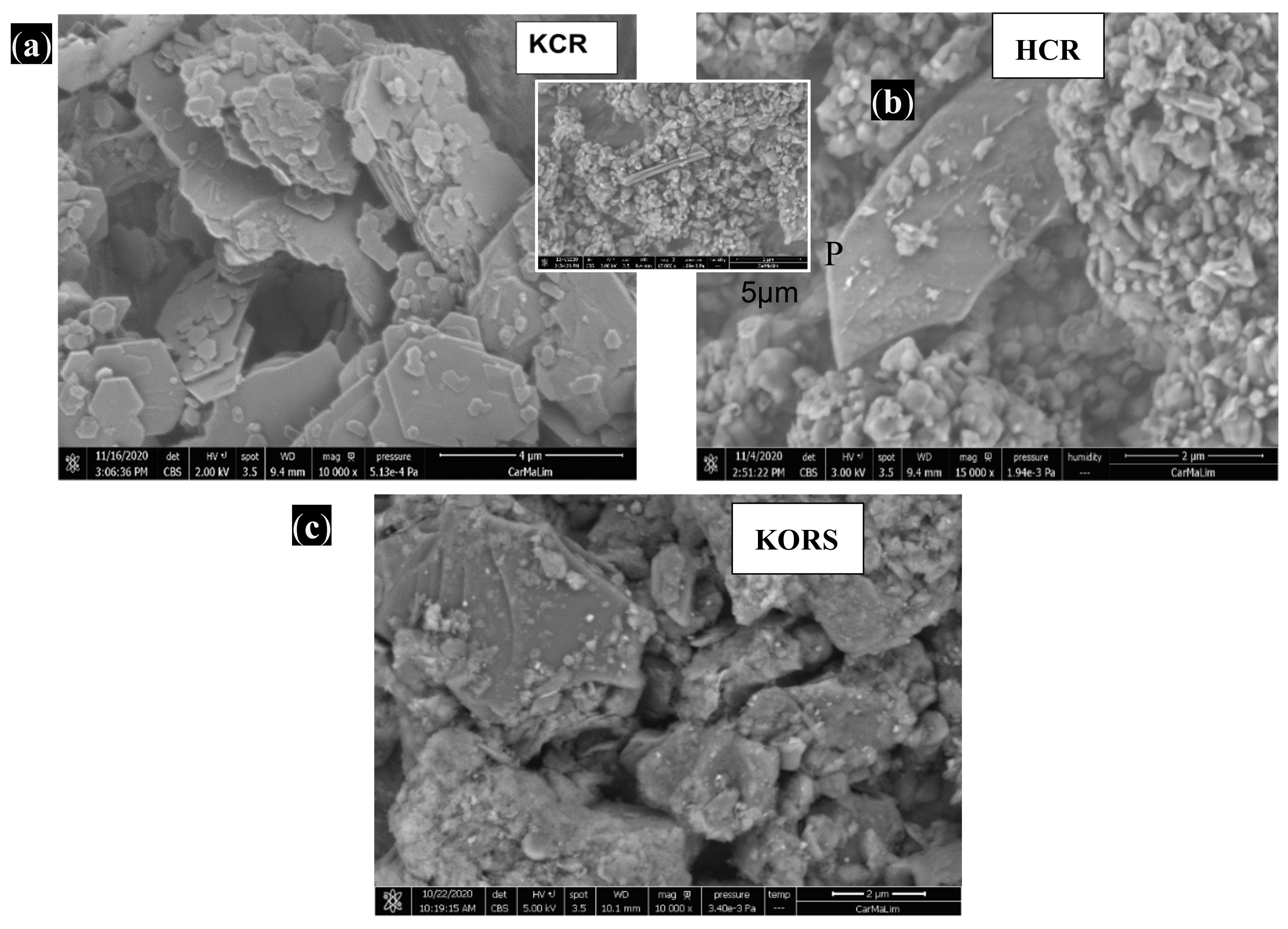
3.1.1. Chemical Analysis, X-ray Diffraction, and Morphological Analysis of Clay Particles

Table 1 shows the chemical composition (XRF analysis) and some physical properties of the clay raw materials. The SiO2/Al2O3 mass content ratio of KCR is ≃1.1, while those of KCR and KORS are 1.7 and 4.0, respectively. KORS is composed of approximately 12 mass % fluxing oxides with 8.2 mass % Fe2O3 and HCR is composed of 3.8 mass % Fe2O3.
The analysis of XRD patterns (Figure 2) shows that the major crystalline phase present in KCR is kaolinite at 98 mass %. HCR is composed of halloysite (77 mass %) and quartz (17 mass %), and KORS is composed of kaolinite (29 mass %,), quartz (44 mass %), and muscovite (11w mass %).
Figure 3 presents the particle morphology of raw clay materials. The crystalline kaolinite platelets found in KCR (Figure 3a) powder have an average thickness (direct measurement on SEM images) of about 73 nm; some particles among them have sizes of around 1 μm, while others are longer, and can reach 3 μm. The particles of Halloysite (Figure 3b) mainly have a spheroidal (ϕ ≃ 250 nm) and tubular (ϕ ≃ 400 nm and length ≃ 3 μm) morphology. There are also halloysite particles with flat sheets, having the shape of platelets with a size of up to 5 μm. Quartz polyhedra were observed in the HCR (Figure 3b) and KORS (Figure 3c) powders with sizes around 23 μm and 27 μm, respectively.

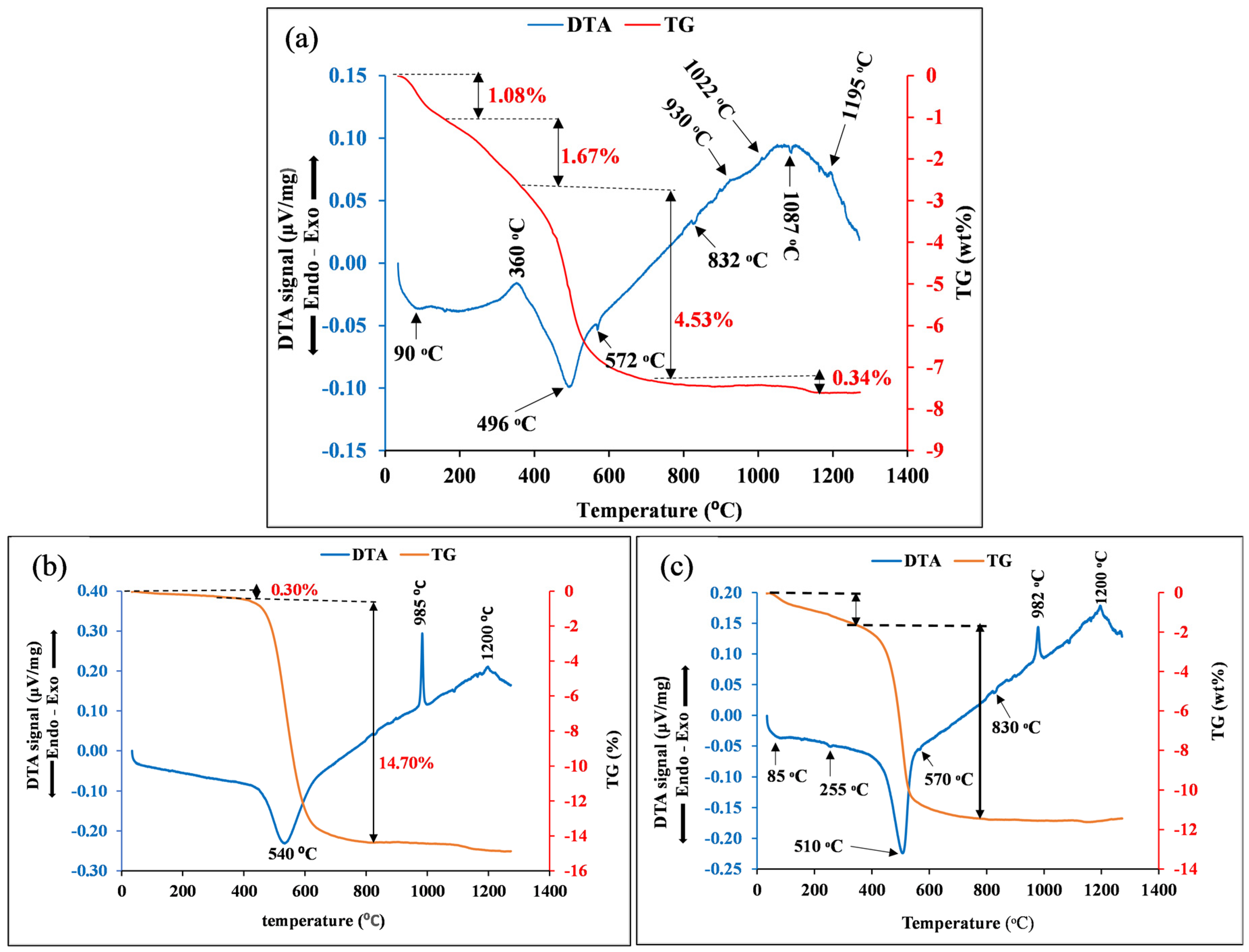
3.1.2. Differential Thermal Analysis (DTA) and TG

The results of the DTA–TG analyses of raw clay materials (KCR, HCR, and KORS) are shown in Figure 4. The TG diagram of KCR (Figure 4b) indicates a small drop from temperatures of 60 °C to around 300 °C, indicating the departure of hydration water related to a mass loss of about 0.3%. This phenomenon is followed by a broad endothermic peak centered at 540, corresponding to the dehydroxylation of kaolinite into metakaolinite, with associated mass loss of approximately 14.7%. The exothermic peak at 985 °C is related to structural reorganization (recrystallization) to form γ-alumina or a spinel structure (over-stoichiometric mullite in Al2O3) [37,38]. The spinel phase formed from recrystallization evolves up to 1200 °C, whereby the primary mullite tends to appear, characterized by the exothermic peak. The TG curve of HCR (Figure 4c) shows a mass loss of 1.6% from 60 °C to 300 °C, which involves two endothermic peaks at 85 °C and 255 °C that correspond respectively to the departure of hygroscopic water from the surface and interlayer particles and the partial dehydroxylation of halloysite –10Å into halloysite –7Å (Figure 4c) [26,39]. The dehydroxylation of halloysite into metahalloysite is shown by the large endothermic peak at 510 °C. The transformation of residual halloysite remaining in the amorphous phase of metahalloysite occurs at 830 °C, as evidenced on the DTA curves. The mass loss associated to halloysite transformation into metahalloysite includes residual dehydroxylation is 10.02%. The exothermic peak at 982 °C corresponds to the recrystallization of metahalloysite in γ-alumina phase or in spinel phase [40,41]. The last exothermic peak at 1200 °C is due to the formation of primary mullite [42]. As for the DTA thermogram of KORS (Figure 4a), the first endothermic peak centered at 90 °C is linked to a mass loss of 1.08% and can be explained by the departure of hygroscopic water from the particles’ surface. The second broad endothermic peak between 125 and 360 °C centered at 200 °C, with a mass loss of 1.67% may correspond to the dehydroxylation of goethite into hematite [39]. The important mass loss of 4.53% is relative to the dehydroxylation of kaolinite into metakaolinite, which is characterized by the endothermic peak at 496 °C. The endothermic peak at 832 °C, with a mass loss of 0.34%, can be related to the dehydroxylation of the muscovite [40]. The exothermic peaks around 930 °C correspond to the recrystallization of metakaolinite into primary mullite [41,42]. The important quantity of fluxing oxides influences the metakaolinite recrystallization. The exothermic peak at 1022 °C would correspond to the formation of the spinel Mg (Al2O4) and/or the spinel Fe (Al2O4) [43]. The last endothermic peak at 1087 °C is relative to the total dehydroxylation of muscovite [44]. The mass loss related to this phenomenon is included in 0.34%. The exothermic peak at 1195 °C is due to the transformation of primary mullite into secondary mullite [42]. The brackets at 572 °C and 570 °C, respectively, in KORS and HCR correspond to the transformation of α quartz into β quartz.

3.2. Slurry Characterization

Figure 5 shows the particle size distribution of the clay suspensions. KCR exhibits a monomodal dispersion with a characteristic size of 7.7 μm. However, HCR and KORS present multimodal distribution, with coarse grain size up to 34.2 μm and 44.5 μm, respectively. Table 2 shows that the particles’ sizes were significantly reduced within the casting suspensions compared to those within the argillaceous suspensions, as expected. Furthermore, the slurries prepared for casting present a monomodal distribution, thanks to the grinding steps and the presence of surfactants. The D90s of as-prepared slurries are lower than those of argillaceous suspensions (clay slurries). The D90 of the HCR slurry (2.6 μm) is relatively lower than that of KCR slurry (3.0 μm). Those of the slurries of KHCR (6.0 μm) and KORS (10.9 μm) are higher, indicating that the particles are less deagglomerated.

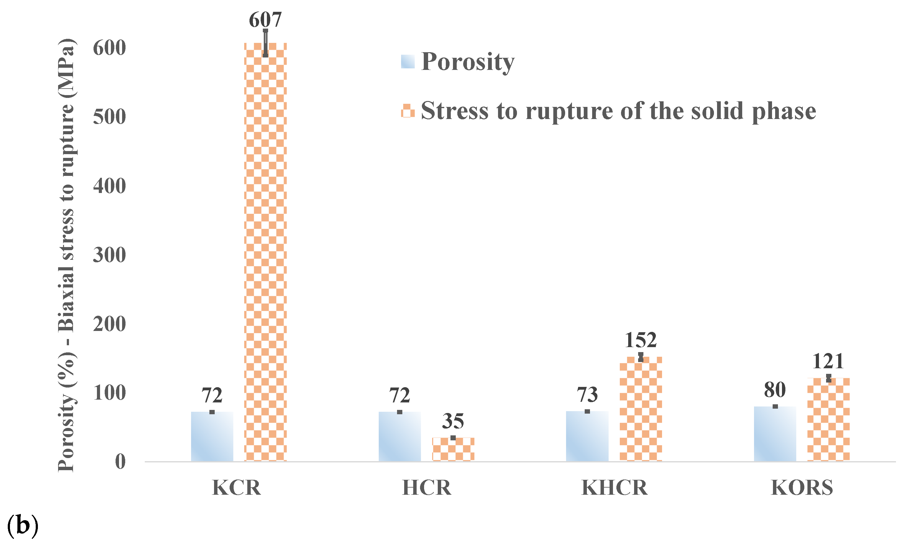
3.3. Characterization of Manufactured Porous Ceramics

Figure 6 shows the results of the biaxial flexural strength and the green tape porosity (before sintering). The evaluated flexural strength is between 3.0 ± 0.6 MPa (HCR) and 7.3 ± 2.2 (KCR) and the porosity between 67 ± 1 vol. % (KCR and HCR) and 80 ± 1 vol. % (KORS). The green tapes of KCR have the highest biaxial bending strength, while those of KORS and HCR have the lowest strength. KORS green tapes are more porous (80 ± 1 vol. %) with a relatively low biaxial flexural strength value. The green tapes of KHCR have porosity higher than those of KCR and HCR and present a flexural strength between the strength values of KCR and HCR.
The SEM images (Figure 7) show a difference in microstructure for all the four green tapes. Furthermore, in the tapes of KCR and HCR (Figure 7 KCR and 7 HCR) the pores are more textured in section with large pores compared to the others. KORS presents a great number of pores with relatively smaller sizes than those of the three others.
Figure 8 shows the results of the biaxial flexural strength and porosity of the textured ceramics, which were obtained at 1200 °C. The biaxial bending values of the specimens are between 4.2 ± 0.7 MPa (HCR) and 70 ± 1.1 MPa (KCR) while the porosity is between 72 ± 2 vol. % (KCR) and 80 ± 1 vol. % (KORS). KORS disks are more porous, with an average value (11 ± 1.1 MPa) of biaxial flexural strength. KCR has the highest biaxial bending strength (70 ± 1.1 MPa) with porosity inferior to that of KORS. HCR ceramic disks have the same porosity rate as KCR; however, they exhibit low biaxial flexural strength (4.2 ± 0.7 MPa) compared to those of KCR. As with the green tapes of KHCR, discs exhibit biaxial flexural strength (17.0 ± 1.3 MPa) between those of HCR and KCR, with comparable porosity values. On Figure 8b, the stress-to-rupture of the solid phase is presented after removal of the pore contribution using the formula of Equation (3) [27]. The observed trend highlights the very low mechanical resistance achieved upon the firing of HCR samples compare to the three other clay samples. It is likely to suggest that in the case of HCR, the mullite type and content are not optimized. SEM observation reveals a difference in microstructure and texture (Figure 9) for all four ceramic disks. In KCR ceramic discs, the pores are more textured, and we noted the formation of the primary mullite in rigid skeleton shape (Figure 9 KCR). SEM images of KORS ceramic disks show the formation of secondary mullite needles with a relatively small quantity and a disordered structure in a vitreous phase (Figure 9 KORS). The relatively important vitreous phase in the porous disks of HCR leads to the bulk formation of small mullite particles (spheroidal halloysite particles transformed into mullite) without skeletons (Figure 9 HCR).
σ =   σ 0 × e b P  
where σ 0 represents the stress-to-rupture of the solid phase, P is the porosity, and b is a constant that can vary from 3 to 7. In the case of such alumino-silicate compositions, the mean value of b is close to 3.8. We have used value of b = 3 in our calculation.
The X-ray diffraction patterns (Figure 10) of disk ceramic sintered at 1200 °C show the presence of mullite in the four ceramics and therefore confirm the SEM observations of Figure 9. In addition to mullite, cristobalite, and hematitephases in KORS ceramic are identified. All of the ceramic tapes, with the exception of the KCR ceramic, indicate the presence of residual quartz.
As mentioned in Section 2.3.2, images were processed using GIMP software and a typical example of a binary image with HCR is on Figure 11, showing the pore morphology and size distribution obtained in this case.
The methodology of image analyses differs from the sample microstructural type. With HCR, the microstructure is obviously heterogeneous (Figure 11), resulting from the preferential densification of clay assemblies, inducing the occurrence of pores between them. The image analysis allows for the distinguishing of the pores, and the resulting distribution of pore density against pore size (Figure 12a) for HCR.
With KORS, the microstructural transformations are mainly from a liquid-phase sintering process, which leads to a more homogenous microstructure. It induces the formation of a reduced number of larger pores from the coalescence of small pores, and the image analysis is able to identify them. The pore density versus the pore size is in Figure 12a, showing a lower density of pores, but with a larger size.
From the SEM image of KCR, we observe a continuous arrangement of fired clay particles where pores tend to be less easily distinguished. However, the particle density against the particle size can be determined in Figure 12b. In such microstructural arrangements, the porosity occurs at the interconnections between particles, which corresponds to a scale much smaller than that of particles. Therefore, a possible representation of pore density obtained from the particle size is also in Figure 12b. Indeed, the pore size is deduced from the particle size, it is clearly much lower than the pore size of the HCR and KORS samples.

4. Discussion

4.1. Powder Characterization

4.1.1. Chemical, Mineralogical, and Morphological Analyses of Clay Particles

The mass content ratio SiO2/Al2O3 (Table 1) of KCR (≃1.1) shows that it is a kaolin with an impressive purity. Those of HCR and KORS are 1.7 and 4.0 (instead of 1.1 for pure kaolinite), respectively, indicating that in addition to 1:1 clay minerals, there is the presence of silica phase in the form of quartz and/or other types of 2:1 clay minerals [24,25]. The high content of fluxing oxides (12 wt. %) within KORS and Fe2O3 (3.8 wt. %) within HCR clay may enhance the occurrence of a liquid phase and mullite at moderated temperatures upon firing [45,46]. However, the relatively important iron oxide content may also have a negative effect during the sintering, due to the important contraction and related crack development, thus weakening the final material [47]. Both the major crystalline-phase analysis (Figure 2) and the chemical composition (Table 1) show that KCR clay (98 wt. % of kaolinite) is more refractory in comparison with HCR clay (77 wt. % of halloysite). Figure 3a shows that KCR clay is essentially composed of hexagonal kaolinitic platelets, which seem well-crystallized. In the case of HCR clay, Figure 3b indicates that its major phase (halloysite –10Å) particles are essentially spheroidal, mixed with a low fraction of tubular-like particles. This trend is due to the influence of iron content on halloysite particle morphology, since the iron is located in the octahedral layer of iron-rich halloysites as reported in literature [25,48]. Therefore, the iron content influences the shape and aspect ratio of particles [25]. In general, platy forms contain relatively large amounts of iron (2–6 wt. % in Fe2O3), whereas tubular particles exhibit low iron content (<3 wt. % Fe2O3). Spheroidal halloysite exhibit a wide range of iron contents, from almost zero up to values comparable to those of tubular halloysite [49]. The iron content within HCR (3.8 wt. % in Fe2O3) is in agreement with those of spheroidal halloysite.

4.1.2. Differential Thermal Analysis (DTA) and TG

According to the results presented on Figure 4, the dehydroxylation phenomenon of kaolinite and halloysite contained within the used clays occurs at around 500 °C. Indeed, the loss of hydroxyl groups takes place by condensation, namely by grouping 2OH into H2O, and by diffusion, particularly along the planes of the sheets [16]. This dehydroxylation deeply disturbs the Al (O, OH)6 octahedral layers. However, the hydroxyl groups close to the SiO4 tetrahedral layers (10% of hydroxyls) can resist within the metakaolinite up to temperatures of 920 °C [37]. According to the researchers P. Yuan et al. (2008b) [50], B. Zhang et al. (2020) [51], and C. R. Kaze et al. (2020) [39], the complete destruction of halloysite into an amorphous phase of metahalloysite occurs between 650 and 850 °C. The structural reorganization of metakaolinite/halloysite occurs at 985 °C (KCR), 982 °C (HCR), and 930 °C (KORS). This difference in the recrystallization temperature can be explained by the content of fluxing oxides within the clay materials (Table 1). A. Raghdi et al. (2017) [42] mentioned that several researchers such as Okada et al. (1986) [52], Brindley and Lemaitre (1987) [53], Sonuparlak et al. (1987) [54], and Huang et al. (2012) [55], had divergent points of view on the recrystallization reaction. This recrystallization would lead to a γ–alumina (γ–Al2O3), or to a spinel phase (over-stoichiometric mullite in Al2O3) and/or nucleation of the primary mullite. At around 1200 °C, the primary mullite type appears within KCR and HCR, while the secondary mullite type appears within KORS. It is important to note that the nature of the mullite type (primary or secondary) in HCR need to be refined because the significant content (3.8 wt. %) of Fe2O3 could activate the formation of secondary mullite [12].

4.2. Slurry Characterization

This particle size distribution presented in Figure 5 shows that KCR and HCR exhibit the most important dispersion of particles within a monomodal distribution centered around 2.3 μm. This behavior can be explained by the fact that the dispersant introduction (0.2 wt. %) into the slurries creates the interaction phenomenon of electrostatic and/or steric repulsion between the particles, followed by their dispersion, as indicated in previous studies [23]. The characteristic D90 values of the particles within the casting suspensions (Table 2) show that KHCR and KORS would likely require a higher or lower quantity of dispersant to better deagglomerate the particles and/or the removal of some coarse quartz grains. According to previous works [28,56,57], the request for a quantity of dispersant to disperse the particles well and achieve optimum stabilization also depends on the nature of the suspension. The low dispersion of KORS particles compared to others could be due to the significant quartz content (44 wt.%). According to previous work of Nadia Houta et al. (2014) [24], kaolinite platelets present three types of surface (siliceous, aluminous, and edges contributions), which is not the case for quartz particles, and this justifies the different interactions between particles and dispersant in the presence of high quartz content. In addition, the low dispersion of the particles within the KHCR mixture compared to KCR and HCR could be explained by the insertion of halloysite particles between kaolinite platelets, followed by the increasing of the particle size. The dispersion of the particles within HCR suspensions could be favored by the particle morphology (mainly spheroidal) of halloysite.

4.3. Characterization of Manufactured Porous Ceramics

The biaxial flexural strength and porosity of the green ceramic disks (sampled from the green tape) shown in Figure 6 indicate that the green ceramic disks of KCR are the most resistant (7.3 ± 0.5 MPa). Indeed, the stacking of inter-bonded kaolinite platelets under the effect of the used organic binder enhances the mechanical strength of the green material. In addition, the flattened shape of the pores (Figure 6 KCR) is less detrimental towards the network compared to the microstructure of the other green ceramic disks. The green tapes of HCR have the same porosity as KCR (67 ± 1 vol. %) but exhibit the lowest biaxial bending strength (3.0 ± 0.6 MPa) which can be explained by the size and geometry, as well as the distribution in size and the interconnectivity of pores after lyophilization (Figure 6 HCR) [22,58]. The green ceramic disks of KORS are more porous (79 ± 1 vol. %), which correlates with their biaxial bending value.
The results obtained for the textured ceramic disks, which are sintered at 1200 °C, are presented in Figure 7 and tend to show the same trend as those obtained with the green ceramic disks (Figure 6). The high value of the biaxial flexural strength of KCR (7.3 ± 0.5 Mpa to 70 ± 1.1 Mpa) with porosity of 72 ± 2 vol. % after sintering at 1200 °C is explained by the mullite formation in skeletal form (Figure 9 KCR and Figure 10) [36,59,60]. Ceramic disks of HCR after sintering always have the lowest biaxial flexural strength (3.0 ± 0.6 Mpa to 4.2 ± 0.7 Mpa) with porosity comparable to those of KCR and KHCR. This could be due to the size, geometry, texture, and size distribution of the pores [4,22,58], but also to the bulk formation of small particles of mullite (Figure 9) without proper skeletons, under the effect of the vitreous phase (Figure 9 HCR). The identification of the crystalline phases presented in Figure 10 shows the predominance of mullite as the main crystalline phase within HCR. The microstructure of KHCR after sintering is significantly improved compared to that of HCR, since its biaxial bending value (5.7 ± 1.0 MPa to 17.0 ± 1.3 MPa) is greater with porosity (73 ± 2 vol. %) in the same order as those of KCR and HCR. This improvement in biaxial flexural strength compared to HCR could be due to both the structuring effect of the primary mullite crystals [37,61] from KCR and the small particles from HCR (Figure 9 KHCR). With a porosity of 80 ± 1%, the relatively low values of the biaxial bending strength (3.4 ± 0.5 MPa to 11 ± 1.1 MPa) of KORS compared to those of KCR and KHCR could be explained on the one hand by the structuring and the quantity of the secondary mullite within a large quantity of a liquid phase after sintering [62], and on the other hand, by the microstructural characteristics (examples: pore size andtexture, pore size distribution, etc.) of KORS presented in Figure 11. The formation of the secondary mullite and the cristobalite within the ceramic disks of KORS is favored by the high content of the fluxing oxides. Previous studies [62] have shown that cristobalite may be responsible for the weakening (lower mechanical strength) of the ceramic materials by generating local flaws during cooling.
The porosity distributions in HCR and KORS are in Figure 12a. They clearly indicate a good correlation between the microstructural characteristics and the pore density against their size distribution. Since they are very important in filtration processes, we show that is possible to control the characteristics of the materials for filtration by the selection of the clay materials type.
For HCR, the sintering leads to a heterogeneous microstructure with a large porosity and a significant average pore size. It is very different with KORS, since a liquid phase sintering process induces the removal of finer pores but leads to the coalescence of larger pores. In that case, the pore average size is relatively large and the pore number density is reduced. For both HCR and KORS, we expect a significant dependence of porosity and permeability with the sintering temperature and time, due to the high kinetics of the densification mechanisms. This increases the process dependence in the characteristics of the filters and in the fabrication cost.
With KCR, a more homogeneous microstructural arrangement is obtained (Figure 12 b) resulting from the processing and the solid-state sintering of non-agglomerated particles (Figure 5). It leads to an inter-particle porosity with a very fine average size. The much higher porosity (Figure 8) is from a high density of fine pores, and the characteristics in the use of such filters are very different from those of HCR and KORS. Furthermore, the limited kinetics of the solid-state sintering of non-agglomerated particles is expected to reduce the effect of the sintering temperature variations in the properties of the filter, making easier the manufacturing process.
Preliminary works [28] on freeze-tape casting have shown a similar porosity (66–79 vol. %). They have also shown [63] that ceramic water filters do not necessarily require a high mechanical strength, since most ceramic disks are inserted into a specific casing. Here we evidence the sufficient mechanical strength of our ceramics.
The most common microstructural characteristics of the four microstructures presented in Figure 7 are the porous texture and the pores’ orientation, which depends on the nature and the morphology of particles in the starting materials. The work of P. L. Rachadel et al. (2017) based on perovskite materials [28] showed that materials with a lamellar pore network (porosity in the range 66–79 vol. %) and a vertical orientation can be obtained that is similar to the flattened pore network of KCR (Figure 7 KCR). We expected similar results when selecting different starting clay materials.
The results showed that the freeze-tape-casting process allows for the manufacturing of ceramic filters with a high porosity (72–80 vol. %,) and a controlled texture. Differently to the freeze-tape-casting process, the compaction process leads to ceramic filters that are less porous and having an uncontrolled porosity. It is evidenced in Table 3 that such porous texture is more advantageous for applications in water filtration because the pore network is in radial orientation, reducing the pore tortuosity. The main characteristics of ceramic filters listed in Table 3 were obtained from literature obtained by the compaction process with a porosity of 41–60 vol.%, and are reported from Ekpunobi et al. (2019) [2], P. Kamgang-Syapnjeu et al. (2020) [4], Mouiya et al. (2019) [10], Kumar et al. (2019) [22], El Qacimi et al. (2019) [58], Saja et al. (2018) [64], Hubadillah et al. (2018) [65], and U.E.; and our samples seemed to be appropriate for microfiltration. Moreover, KCR could be used for ultrafiltration purposes.

5. Conclusions

The objective of this work was to characterize the microstructure and mechanical resistance of porous textured ceramics, which are produced by the freeze-tape-casting process. The purpose of using different raw materials (clays) rich in kaolinite or halloysite was to compare the obtained results with another and then draw conclusions. Therefore, the raw materials were first characterized by chemical analysis, X ray diffraction, and particle morphology. Indeed, the chemical composition (XRF analysis) shows, in order of refractoriness, KCR (Al2O3, 40.4 wt. %), HCR (Al2O3, 30.3 wt. %), and KORS (Al2O3, 16.1 wt. %). In addition, the mineralogy by XRD indicates that KCR is mainly composed of kaolinite (98 wt. %); HCR of halloysite (77 wt. %), quartz (17 wt. %), and hematite (4 wt. %); and KORS of kaolinite (29 wt. %), quartz (44 wt. %), muscovite (11 wt. %), and Goethite (9 wt. %). The morphology of the clay particles is essentially platelet (kaolinite), spheroidal, and tubular (halloysite). The measurement of particle size distribution showed that the particles within the suspension of HCR (D90, 2.6 μm) are more dispersed, followed by those within KCR (D90, 3.0 μm) and KORS suspensions. KORS ceramic discs are slightly more porous compared to disks obtained with HCR or KCR. Besides, the samples obtained with KCR are significantly more resistant in biaxial bending. The porosity of sintered ceramic discs is between 72 ± 2 vol. % (KCR and HCR) against 67 ± 1 vol. % (KCR and HCR) for green discs. The porosities of the KORS and KHCR samples are not significantly changed upon sintering at 1200 °C. The biaxial bending values of the sintered discs are between 3.5 ± 0.7 MPa (HCR) and 70 ± 1.1 MPa (KCR) against 3 ± 0.6 MPa (HCR) and 7.3 ± 0.5 (KCR) for green discs. These results are interesting according to previous studies. At this stage of the study, the comparison of the results with those of the literature allows suggestion that the textured ceramic discs with the selected clays could be suitable for microfiltration applications. Furthermore, KCR seems to be better in regard to the final mechanical strength and could be used for ultrafiltration. However, further tests such as permeability and biofilm sensitivity will be helpful in order to confirm or deny these final applications.

Author Contributions

Conceptualization, G.L.L.-N., C.P., M.F. and K.B.; Methodology, G.L.L.-N., K.B. and P.B.; Software, G.L.L.-N., K.B. and P.B.; Validation, G.L.L.-N. and P.B.; Formal Analysis, K.B., G.L.L.-N. and P.B.; Investigation, K.B., G.L.L.-N., M.F., and P.B.; Resources, C.P., M.S., G.L.L.-N. and M.F.; Data Curation, G.L.L.-N., K.B. and P.B.; Writing-Original Draft Preparation G.L.L.-N. and K.B.; Writing–Review & Editing, G.L.L.-N., K.B. and P.B.; Visualization, G.L.L.-N. and K.B.; Supervision, G.L.L.-N., M.S., P.B. and C.P.; Project Administration, G.L.L.-N., M.S., C.P. and P.B.; Funding Acquisition, G.L.L.-N., M.S., C.P. and P.B.. All authors have read and agreed to the published version of the manuscript.

Funding

This research received no external funding.

Institutional Review Board Statement

Not applicable.

Informed Consent Statement

Not applicable.

Conflicts of Interest

The authors declare no conflict of interest.

References

  1. Chaukura, N.; Chiworeso, R.; Gwenzi, W.; Motsa, M.M.; Munzeiwa, W.; Moyo, W.; Chikurunhe, I.; Nkambule, T.T.I. A new generation low-cost biochar-clay composite ‘biscuit’ ceramic filter for point-of-use water treatment. Appl. Clay Sci. 2020, 185, 105409. [Google Scholar] [CrossRef]
  2. Ekpunobi, U.E.; Agbo, S.U.; Ajiwea, V.I.E. Evaluation of the mixtures of clay, diatomite and sawdust for production of ceramic pot filters for water treatment interventions using locally sourced materials. J. Environ. Chem. Eng. 2019, 7, 102791. [Google Scholar] [CrossRef]
  3. Akosile, S.I.; Ajibade, F.O.; Lasisi, K.H.; Ajibade, T.F.; Adewumi, J.R.; Babatola, J.O.; Oguntuase, A.M. Performance evaluation of locally produced ceramic filters for household water treatment in Nigeria. Sci. Afr. 2020, 7, e00218. [Google Scholar] [CrossRef]
  4. Kamgang-Syapnjeu, P.; Njoya, D.; Kamseu, E.; Cornette de Saint Cyr, L.; Marcano-Zerpa, A.; Balme, S.; Bechelany, M.; Soussan, L. Elaboration of a new ceramic membrane support from Cameroonian clays, coconut husks and eggshells: Application for Escherichia coli bacteria retention. Appl. Clay Sci. 2020, 198, 105836. [Google Scholar] [CrossRef]
  5. Khemakhem, I.; Gargouri, O.D.; Dhouib, A.; Ayadi, M.A.; Bouaziz, M. Oleuropein rich extract from olive leaves by combining microfiltration, ultrafiltration and nanofiltration. Separ. Purif. Technol. 2017, 172, 310–317. [Google Scholar] [CrossRef]
  6. Vyatskikh, A.; Kudo, A.; Delalande, S.; Greer, J.R. Additive manufacturing of polymer-derived titania for one-step solar water purification. Mater. Today Commun. 2018, 15, 288–293. [Google Scholar] [CrossRef]
  7. Alghamdi, H.; Dakhane, A.; Alum, A.; Abbaszadegan, M.; Mobasher, B.; Neithalath, N. Synthesis and characterization of economical, multi-functional porous ceramics based on abundant aluminosilicates. Mater. Des. 2018, 152, 10–21. [Google Scholar] [CrossRef]
  8. Pia, G.; Casnedi, L.; Sanna, U. Porous ceramic materials by pore-forming agent method: An intermingled fractal units analysis and procedure to predict thermal conductivity. Ceram. Int. 2015, 41, 6350–6357. [Google Scholar] [CrossRef]
  9. Nishihora, R.K.; Rachadel, P.L.; Quadri, M.G.N.; Hotza, D. Manufacturing porous ceramic materials by tape casting—A review. J. Eur. Ceram. Soc. 2018, 38, 988–1001. [Google Scholar] [CrossRef]
  10. Mouiya, M.; Bouazizi, A.; Abourriche, A.; Benhammou, A.; El Hafiane, Y.; Ouammou, M.; Abouliatim, Y.; Younssi, S.A.; Smithe, A.; Hannache, H. Fabrication and characterization of a ceramic membrane from clay and banana peel powder: Application to industrial wastewater treatment. Mater. Chem. Phys. 2019, 227, 291–301. [Google Scholar] [CrossRef]
  11. Jeong, Y.; Lee, S.; Hong, S.; Park, C. Preparation, characterization and application of low-cost pyrophyllite-alumina composite ceramic membranes for treating lowstrength domestic wastewater. J. Membr. Sci. 2017, 536, 108–115. [Google Scholar] [CrossRef]
  12. Samain, L.; Jaworski, A.; Edén, M.; Ladd, D.M.; Seo, D.K.; Garcia-Garcia, F.J.; Häussermann, U. Structural analysis of highly porous γ-Al2O3. J. Solid State Chem. 2014, 217, 1–8. [Google Scholar] [CrossRef]
  13. Fan, P.; Zhen, K.; Zan, Z.; Chao, Z.; Jian, Z.; Yun, J. Preparation and development of porous ceramic membrane supports fabricated by extrusion technique. Chem. Eng. Trans. 2016, 55, 277–282. [Google Scholar]
  14. Wang, H.E.; Xi, L.J.; Ma, R.G.; Lu, Z.G.; Chung, C.Y.; Bello, I.; Zapien, J.A. Microwave assisted hydrothermal synthesis of porous SnO2 nanotubes and their lithium ion storage properties. J. Solid State Chem. 2012, 190, 104–110. [Google Scholar] [CrossRef]
  15. Zhang, F.Z.; Kato, K.; Fuji, M.; Takahashi, M. Gelcasting fabrication of porous ceramics using a continuous process. J. Eur. Ceram. Soc. 2006, 26, 667–671. [Google Scholar] [CrossRef]
  16. Hou, Z.; Cui, B.; Liu, L.; Liu, Q. Effect of the different additives on the fabrication of porous kaolin-based mullite ceramics. Ceram. Int. 2016, 42, 17254–17258. [Google Scholar] [CrossRef]
  17. Guo, H.; Li, W.; Ye, F. Low-cost porous mullite ceramic membrane supports fabricated from kyanite by casting and reaction sintering. Ceram. Int. 2016, 42, 4819–4826. [Google Scholar] [CrossRef]
  18. Dabir, S.; Deng, W.; Sahimi, M.; Tsotsis, T. Fabrication of silicon carbide membranes on highly permeable supports. J. Membr. Sci. 2017, 537, 239–247. [Google Scholar] [CrossRef]
  19. Mouiya, M.; Abourriche, A.; Bouazizi, A.; Benhammou, A.; El Hafiane, Y.; Abouliatim, Y.; Nibou, L.; Oumam, M.; Ouammou, M.; Smith, A.; et al. Flat ceramic microfiltration membrane based on natural clay and Moroccan phosphate for desalination and industrial wastewater treatment. Desalination 2018, 427, 42–50. [Google Scholar] [CrossRef]
  20. Achiou, B.; Elomari, H.; Bouazizi, A.; Karim, A.; Ouammou, M.; Albizane, A.; Bennazha, J.; Alami, Y.S.; El Amrani, I.E. Manufacturing of tubular ceramic microfiltration membrane based on natural pozzolan for pretreatment of seawater desalination. Desalination 2017, 419, 181–187. [Google Scholar] [CrossRef]
  21. He, Y.; Huang, G.; An, C.; Huang, J.; Zhang, P.; Chen, X.; Xin, X. Reduction of Escherichia coli using ceramic disk filter decorated by nano-TiO2: A low-cost solution for household water purification. Sci. Total Environ. 2018, 616, 1628–1637. [Google Scholar] [CrossRef] [PubMed]
  22. Kumar, M.; Roshni, M.; Vasanth, D. Treatment of aqueous bacterial solution using ceramic membrane prepared from cheaper clays: A detailed investigation of fouling and cleaning. J. Water Proc. Eng. 2019, 29, 100797. [Google Scholar] [CrossRef]
  23. Hammas, A.; Lecomte-Nana, G.L.; Azril, N.; Daou, I.; Peyratout, C.; Zibouche, F. Kaolinite-Magnesite Based Ceramics. Part I: Surface Charge and Rheological Properties Optimization of the Suspensions for the Processing of Cordierite-Mullite Tapes. Minerals 2019, 9, 757. [Google Scholar] [CrossRef] [Green Version]
  24. Houta, N.; Lecomte-Nana, G.L.; Tessier-Doyen, N.; Peyratout, C. Dispersion of phyllosilicates in aqueous suspensions: Role of the nature and amount of surfactant. J. Colloid Interface Sci. 2014, 425, 67–74. [Google Scholar] [CrossRef]
  25. Bauluz, B. Halloysite and kaolinite: Two clay minerals with geological and technological importance. Rev. Real. Acad. Ciencias. Zaragoza 2015, 70, 7–38. [Google Scholar]
  26. Barretoa, I.A.R.; da Costa, M.L. Sintering of red ceramics from yellow Amazonian latosols incorporated with illitic and gibbsitic clay. Appl. Clay Sci. 2018, 152, 124–130. [Google Scholar] [CrossRef]
  27. Daniel, S.; Tessier-Doyen, N.; Dublanche-Tixier, C.; Chateigner, D.; Blanchart, P. Pocesing and characterization of textured mullite ceramics from phyllosilicates. J. Eur. Ceram. Soc. 2010, 30, 2427–2434. [Google Scholar] [CrossRef]
  28. Rachadel, P.L.; Souza, D.F.; Nunes, E.H.M.; Deniz da Costa, J.C.; Vasconcelos, W.L.; Hotza, D. A novel route for manufacturing asymmetric BSCF-based perovskite structure by tape and freeze casting method. J. Eur. Ceram. Soc. 2017, 37, 5249–5257. [Google Scholar] [CrossRef]
  29. Jin, W.; Li, S.; Huang, P.; Xu, N.; Shi, J. Preparation of an asymetric perovskite-type membrane and its oxygen permeability. J. Membr. Sci. 2001, 185, 237–243. [Google Scholar] [CrossRef]
  30. International Organization for Standard (ISO). ISO 10545-3:2018(E) Ceramic Tiles—Part 3: Determination of Water Absorption, Apparent Porosity, Apparent Relative Density and Bulk Density, 2nd edition; ICS 97.150; International Organization for Standardization ISO: Geneva, Switzerland, 2018; pp. 1–18. [Google Scholar]
  31. Schneider, C.A.; Rasband, W.S.; Eliceiri, K.W. NIH Image to ImageJ: 25 years of image analysis. Nat. Methods 2012, 9, 671–675. [Google Scholar] [CrossRef]
  32. Sparavigna, A.C. Image Segmentation Applied to the Study of Micrographs of Cellular Solids. Inter. J. Sci. 2017, 2, 68–76. [Google Scholar] [CrossRef] [Green Version]
  33. ASTM F394-78. Test Method for Biaxial Flexure Strength (Modulus of Rupture) of Ceramic Substrates (Withdrawn 2001); American Society of Testing and Materials Annual Book of Standards, ASTM: West Conshohocken, PA, USA, 1995; Volume 15.01, pp. 469–473.
  34. Padunglappisit, C.; Posaya-anuwat, S.; Sompoch, V.; Piyawiwattanakoon, P.; Panpisut, P. Effects of Different Amine Activators on the Monomer Conversion, Biaxial Flexural Strength, and Color Stability of Experimental Provisional Dental Restorations. Eur. J. Dent. 2021, 15, 488–494. [Google Scholar] [CrossRef] [PubMed]
  35. Kirstein, A.F.; Woolley, R.M. Symmetrical bending of thin circular elastic plates on equally spaced point supports. J. Res. Natl. Bur. Stand. C. Eng. Instrum. 1967, 71C, 1–10. [Google Scholar] [CrossRef]
  36. Glandus, J.C. Meaning of the biaxial flexure tests of discs for strength measurements. J. Phys. Colloq. 1986, 47, C1-595–C1-600. [Google Scholar] [CrossRef]
  37. Chargui, F.; Hamidouchea, M.; Belhouchet, H.; Jorande, Y.; Doufnoune, R.; Fantozzi, G. Mullite fabrication from natural kaolin and aluminium slag. Boletín Socieda Spañola Cerámica Y Vidr. 2018, 57, 169–177. [Google Scholar] [CrossRef]
  38. Srikrishna, K.; Thomas, G.; Martinez, R.; Corral, M.P.; Moya, J.S. Kaolinite-mullite reaction series: A TEM study. J. Mater. Sci. 1990, 25, 607–612. [Google Scholar] [CrossRef]
  39. Kaze, C.R.; Alomayri, T.; Hasan, A.; Tomed, S.; Lecomte-Nana, G.L.; Nemaleu, J.G.N.; Tchakout, H.K.; Kamseu, E.; Melo, U.C.; Rahier, H. Reaction kinetics and rheological behaviour of meta-halloysite based geopolymer cured at room temperature: Effect of thermal activation on physicochemical and microstructural properties. Appl. Clay Sci. 2020, 196, 105773. [Google Scholar] [CrossRef]
  40. Krasilin, A.A.; Danilovich, D.P.; Yudina, E.B.; Bruyere, S.; Ghanbajad, J.; Ivanov, V.K. Crystal violet adsorption by oppositely twisted heat-treated halloysite and pecoraite nanoscrolls. Appl. Clay Sci. 2019, 173, 1–11. [Google Scholar] [CrossRef]
  41. Yuan, P. Thermal-treatment-induced deformations and modifications of halloysite. Dev. Clay Sci. Nanosized Tubul. Clay Miner. 2016, 7, 137–166. [Google Scholar]
  42. Raghdi, A.; Heraiz, M.; Sahnoune, F.; Saheb, N. Mullite-zirconia composites prepared from halloysite reaction sintered with boehmite and zirconia. Appl. Clay Sci. 2017, 146, 70–80. [Google Scholar] [CrossRef]
  43. He, X.; Li, C.; Liu, J.; Huang, Q.; Shen, X.; Liu, T.; Lu, A. Glass forming ability, structure and properties of Cr2O3–Fe2O3 co-doped MgO–Al2O3–SiO2–B2O3 glasses and glass-ceramics. J. Non-Cryst. Solids 2020, 529, 119779. [Google Scholar] [CrossRef]
  44. Mariani, E.; Brodie, K.H.; Rutter, E.H. Experimental deformation of muscovite shear zones at high temperatures under hydrothermal conditions and the strength of phyllosilicate-bearing faults in nature. J. Struct. Geol. 2006, 28, 1569–1587. [Google Scholar] [CrossRef]
  45. Aras, A. The difference between alkaline and alkaline earth effects on high-temperature phase change of clay-based ceramic. Appl. Clay Sci. 2018, 164, 2–12. [Google Scholar] [CrossRef]
  46. Viswabaskaran, V.; Gnanam, F.D.; Balasubramanian, M. Effect of MgO, Y2O3 and boehmite additives on the sintering behavior of mullite formed from kaolinite reactive alumina. J. Mater. Proc. Technol. 2003, 142, 275–281. [Google Scholar] [CrossRef]
  47. Morales-Morales, J.A. Synthesis of Hematite α-Fe2O3 Nano Powders by the controlled precipitation method. Cienc. Desarro. 2017, 8, 99–107. [Google Scholar] [CrossRef] [Green Version]
  48. Hart, R.D.; Gilkes, R.J.; Siradz, S.; Singh, B. The nature of soil kaolins from Indonesia and Western Australia. Clay Miner. 2002, 50, 198–207. [Google Scholar] [CrossRef]
  49. Joussein, E.; Petit, S.; Churchman, J.; Theng, B.; Righi, D.; Delvau, B. Halloysite clay minerals—A review. Clay Miner. 2005, 40, 383–426. [Google Scholar] [CrossRef]
  50. Peng, Y.; Southon, P.D.; Liu, Z.; Green, M.E.R.; Hook, J.M.; Antill, S.J.; Kepert, C.J. Functionalization of halloysite clay nanotubes by grafting with γ-aminopropyltriethoxysilane. J. Phys. Chem. C 2008, 112, 15742–15751. [Google Scholar]
  51. Zhang, B.; Haozhe, G.; Peng, Y.; Wang, L.Y.; Deng, Q.; Liu, L.D. Geopolymerization of halloysite via alkali-activation: Dependence of microstructures on precalcination. Appl. Clay Sci. 2020, 185, 105375. [Google Scholar] [CrossRef]
  52. Okada, K.; Otsuka, N.; Ossaka, J. Characterization of spinel phase formed in the kaolin-mullite thermal sequence. J. Am. Ceram. Soc. 1986, 69, C1-251–C1-253. [Google Scholar] [CrossRef]
  53. Brindley, G.W.; Lemaitre, J. Thermal, oxidation and reduction reactions of clay minerals. Monogr. Mineral. Soc. 1987, 6, 319–370. [Google Scholar]
  54. Sonuparlak, B.; Sarikaya, M.; Aksay, I.A. Spinel phase formation during the 980 °C exothermic reaction in the kaolinite-to-mullite reaction series. J. Am. Ceram. Soc. 1987, 70, 837–842. [Google Scholar] [CrossRef]
  55. Huang, C.Y.; Ko, C.C.; Chen, L.H.; Huang, C.T.; Tung, K.L.; Liao, Y.C. A simple coating method to prepare super hydrophobic layers on ceramic alumina for vacuum membrane distillation. Separ. Purif. Technol. 2018, 198, 79–86. [Google Scholar] [CrossRef]
  56. Dong, Q.; Zhu, T.; Xie, Z.; Han, Y.; An, D. Optimization of the tape slurries for high-quality zirconia substrates. Ceram. Inter. 2017, 43, 16943–16949. [Google Scholar] [CrossRef]
  57. Luo, J.; Eitel, R. Aqueous tape casting of Al2O3 for multilayer co-fired ceramic based microfluidic chips with translucent windows. Ceram. Int. 2018, 44, 3488–3491. [Google Scholar] [CrossRef]
  58. El Qacimi, N.; El Baraka, N.; Saffaj, N.; Mamouni, R.; Laknifli, A.; Alami, Y.S.; Faouzi, A.; Zidouh, H. Preparation and characterization of flat membrane support based on Sahara Moroccan clay: Application to the filtration of textile effluents. Desalin. Water Treat. 2019, 143, 111–117. [Google Scholar] [CrossRef]
  59. Aladesuyi, O.; Pal, M.; Das, S.K.; Ajanaku, K.O. Phase and microstructural evolution during sintering of mixture of 75:25 Nigerian kaolin and calcined alumina powder compacts. J. Mater. Environ. Sci. 2017, 8, 2682–2838. [Google Scholar]
  60. Zemánek, D.; Lang, K.; Tvrdík, L.; Všianský, D.; Nevrivová, L.; Štursa, P.; Kovár, P.; Keršnerová, L.; Dvorák, K. Development and Properties of New Mullite Based Refractory Grog. Materials 2021, 14, 779. [Google Scholar] [CrossRef]
  61. Martín-Márquez, J.; Rincón, J.M.; Romero, M. Mullite development on firing in porcelain stoneware bodies. J. Eur. Ceram. Soc. 2010, 7, 599–1607. [Google Scholar] [CrossRef] [Green Version]
  62. Aras, A.; Kristaly, F. α-Cristobalite formation in ceramic tile and sewage pipe bodies derived from Westerwald ball clay and its effect on elastic-propertie. Appl. Clay Sci. 2019, 178, 105–126. [Google Scholar] [CrossRef]
  63. Soppe, A.I.A.; Heijman, S.G.J.; Gensburger, I.; Shantz, A.; Halem, D.V.; Kroesbergen, J.; Wubbels, G.H.; Smeets, P. Critical parameters in the production of ceramic pot filters for household water treatment in developing countries. J. Water Health 2015, 13, 587–599. [Google Scholar] [CrossRef] [PubMed]
  64. Saja, S.; Bouazizi, A.; Achiou, B.; Ouammou, M.; Albizane, A.; Bennazha, J.; Younssi, S.A. Elaboration and characterization of low-cost ceramic membrane made from natural Moroccan perlite for treatment of industrial wastewater. J. Environ. Chem. Eng. 2018, 6, 451–458. [Google Scholar] [CrossRef]
  65. Hubadillah, S.K.; Othman, M.H.D.; Ismail, A.F.; Rahman, M.A.; Jaafar, J.; Iwamoto, Y.; Honda, S.; Dzahir, M.I.H.M.; Yusop, M.Z.M. Fabrication of low cost, green silica based ceramic hollow fibre membrane prepared from waste rice husk for water filtration application. Ceram. Int. 2018, 44, 10498–10509. [Google Scholar] [CrossRef]
Figure 1. Diagram of freeze-tape-casting device and images of freeze-tape-cast disk samples after freeze-drying and after sintering at 1200 °C.
Ceramics 05 00007 g001
Figure 2. XRD patterns of raw materials.
Ceramics 05 00007 g002
Figure 3. SEM images of particle morphology of (a) KCR, (b) HCR, and (c) KORS powders. P = Primary mullite.
Ceramics 05 00007 g003
Figure 4. Differential thermal analysis (DTA) and thermogravimetry (TG) curves of (a) KORS, (b) KCR, and (c) HCR.
Ceramics 05 00007 g004
Figure 5. Particle size distribution of the clay-based suspensions prepared for freeze-tape casting (obtained after milling and sieving).
Ceramics 05 00007 g005
Figure 6. Biaxial flexural strength and porosity of manufactured green tapes (before sintering).
Ceramics 05 00007 g006
Figure 7. SEM images (surface and section) of the green tapes before sintering at 1200 °C.
Ceramics 05 00007 g007
Figure 8. Biaxial flexural strength and porosity of (a) manufactured porous ceramics and (b) corresponding solid-phase stress-to-rupture. Discs sintered at 1200 °C.
Ceramics 05 00007 g008aCeramics 05 00007 g008b
Figure 9. SEM images realized in the section of the manufactured porous ceramics (discs sintered at 1200 °C. P = Primary mullite; S = Secondary mullite.
Ceramics 05 00007 g009
Figure 10. (a) XRD patterns of manufactured porous ceramics, illustration of the (b) (110) peak, and (c) the (210), (120) doublet of mullite.
Ceramics 05 00007 g010
Figure 11. Typical binary image with HCR.
Ceramics 05 00007 g011
Figure 12. (a) Pore numbers per μm2 of HCR (•) and KORS (o) against the pore size; (b) Grain (•) and pore numbers (thick line) of KCR per μm2 against the grain and pore sizes.
Ceramics 05 00007 g012
Table 1. Chemical composition (XRF analysis) and other characteristic physical properties of the starting powders.
Chemical Composition (Mass %)
RawSSA (BET)
(m2·g−1)
Density Materials
(g·cm−3)
Al2O3SiO2Fe2O3K2ONa2OMgOCaOTiO2Loss of Ignition at 1050 °C
KCR 6.0 ± 0.12.640.442.20.70.1---0.416.0
HCR 28.1± 0.22.630.352.53.80.20.1-0.10.412.0
KORS 31.4 ± 0.32.716.163.98.21.30.20.50.21.38.0
Table 2. Characteristic grain size (derived from Figure 2) of the prepared clay suspensions.
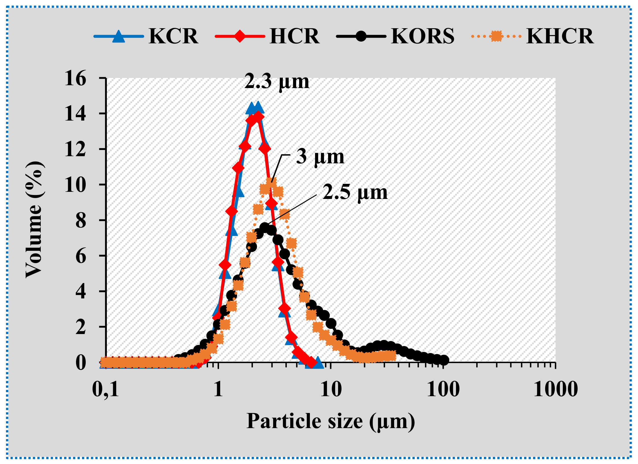
Clay Suspensions Label
KCRHCRKORSKHCR
D10 (μm) 1.21.01.21.2
D90 (μm) 3.02.610.96.0
Table 3. Characteristics of different ceramic filters from the literature ([2,4,10,22,58,64,65]), in comparison to those of the clay ceramics from this study.
ProcessReverse OsmosisNanofiltrationUltrafiltrationMicrofiltration
Pore sizeDense membrane0.5–2 nm2–50 nm0.1–10 μm
Transmembrane
pressure (bar)
30–1005–301–50.5–2
Pore classificationUltra micropores (<0.7 nm)Micropores (0.7–2 nm)Mésopores (2–50 nm)Macropores (50 nm)
Present work KCRKCR, HCR, KHCR, and KORS
Publisher’s Note: MDPI stays neutral with regard to jurisdictional claims in published maps and institutional affiliations.

