
Three-Dimensional Finite Element Analysis of Different Connector Designs for All-Ceramic Implant-Supported Fixed Dental Prostheses


Abstract
:
1. Introduction
2. Materials and Methods
3. Results
4. Discussion
5. Conclusions
Author Contributions
Funding
Institutional Review Board Statement
Informed Consent Statement
Conflicts of Interest
References
- Seghi, R.; Denry, I.; Rosenstiel, S. Relative fracture toughness and hardness of new dental ceramics. J. Prosthet. Dent. 1995, 74, 145–150. [Google Scholar] [CrossRef]
- de Jager, N.; Münker, T.J.; Guilardi, L.F.; Jansen, V.J.; Sportel, Y.G.; Kleverlaan, C.J. The relation between impact strength and flexural strength of dental materials. J. Mech. Behav. Biomed. Mater. 2021, 122, 104658. [Google Scholar] [CrossRef] [PubMed]
- Nishioka, G.; Prochnow, C.; Firmino, A.; Amaral, M.; Bottino, M.A.; Valandro, L.F.; De, M.R.M. Fatigue strength of several dental ceramics indicated for CAD-CAM monolithic restorations. Braz. Oral Res. 2018, 32. [Google Scholar] [CrossRef] [PubMed]
- Arena, A.; Prete, F.; Rambaldi, E.; Bignozzi, M.C.; Monaco, C.; Di Fiore, A.; Chevalier, J. Nanostructured Zirconia-Based Ceramics and Composites in Dentistry: A State-of-the-Art Review. Nanomaterials 2019, 9, 1393. [Google Scholar] [CrossRef] [PubMed] [Green Version]
- Holand, W.; Schweiger, M.; Frank, M.; Rheinberger, V. A comparison of the microstructure and properties of the IPS Empress 2 and the IPS Empress glass-ceramics. J. Biomed. Mater. Res. 2000, 53, 297–303. [Google Scholar] [CrossRef]
- McLaren, E.; White, S.N. Glass-infiltrated zirconia/alumina-based ceramic for crowns and fixed partial dentures. Pract.l Periodontics Aesthet. Dent.: PPAD 1999, 11, 985–994. [Google Scholar]
- Denry, I.; Kelly, J. Emerging Ceramic-based Materials for Dentistry. J. Dent. Res. 2014, 93, 1235–1242. [Google Scholar] [CrossRef] [Green Version]
- Kelly, J.R.; Benetti, P. Ceramic materials in dentistry: Historical evolution and current practice. Aust. Dent. J. 2011, 56, 84–96. [Google Scholar] [CrossRef]
- Jones, D.W. Development of dental ceramics. An historical perspective. Dent. Clin. N. Am. 1985, 29, 621–644. [Google Scholar]
- Callister, W.D.R.D.G. Materials Science And Engineering: An Introduction; Wiley: Hoboken, NJ, USA, 2010. [Google Scholar]
- Fischer, H.; Weber, M.; Marx, R. Lifetime Prediction of All-ceramic Bridges by Computational Methods. J. Dent. Res. 2003, 82, 238–242. [Google Scholar] [CrossRef]
- Inan, O.; Seçilmiş, A.; Eraslan, O. Effect of pontic framework design on the fracture resistance of implant-supported all-ceramic fixed partial dentures. J. Appl. Oral Sci. 2009, 17, 533–538. [Google Scholar] [CrossRef]
- Pjetursson, B.E.; Sailer, I.; Makarov, N.A.; Zwahlen, M.; Thoma, D.S. All-ceramic or metal-ceramic tooth-supported fixed dental prostheses (FDPs)? A systematic review of the survival and complication rates. Part II: Multiple-unit FDPs. Dent. Mater. 2015, 31, 624–639. [Google Scholar] [CrossRef] [Green Version]
- Sailer, I.; Balmer, M.; Hüsler, J.; Hämmerle, C.H.F.; Känel, S.; Thoma, D. 10-year randomized trial (RCT) of zirconia-ceramic and metal-ceramic fixed dental prostheses. J. Dent. 2018, 76, 32–39. [Google Scholar] [CrossRef] [Green Version]
- Kelly, J.; Tesk, J.; Sorensen, J. Failure of All-ceramic Fixed Partial Dentures in vitro and in vivo: Analysis and Modeling. J. Dent. Res. 1995, 74, 1253–1258. [Google Scholar] [CrossRef]
- Lang, L.A.; Wang, R.-F.; Kang, B.; White, S.N. Validation of finite element analysis in dental ceramics research. J. Prosthet. Dent. 2001, 86, 650–654. [Google Scholar] [CrossRef] [PubMed]
- White, S.; Miklus, V.; McLaren, E.; Lang, L.; Caputo, A. Flexural strength of a layered zirconia and porcelain dental all-ceramic system. J. Prosthet. Dent. 2005, 94, 125–131. [Google Scholar] [CrossRef]
- Pjetursson, B.E.; Heimisdottir, K. Dental implants–Are they better than natural teeth? Eur. J. Oral Sci. 2018, 126, 81–87. [Google Scholar] [CrossRef] [PubMed] [Green Version]
- Gherlone, E.; Capparé, P.; Tecco, S.; Polizzi, E.; Pantaleo, G.; Gastaldi, G.; Grusovin, M.G. Implant Prosthetic Rehabilitation in Controlled HIV-Positive Patients: A Prospective Longitudinal Study with 1-Year Follow-Up. Clin. Implant. Dent. Relat. Res. 2015, 18, 725–734. [Google Scholar] [CrossRef] [PubMed]
- Sailer, I.; Strasding, M.; Valente, N.A.; Zwahlen, M.; Liu, S.; Pjetursson, B.E. A systematic review of the survival and complication rates of zirconia-ceramic and metal-ceramic multiple-unit fixed dental prostheses. Clin. Oral Implant. Res. 2018, 29, 184–198. [Google Scholar] [CrossRef] [PubMed] [Green Version]
- Ambré, M.J.; Aschan, F.; von Steyern, P.V. Fracture Strength of Yttria-Stabilized Zirconium-Dioxide (Y-TZP) Fixed Dental Prostheses (FDPs) with Different Abutment Core Thicknesses and Connector Dimensions. J. Prosthodont. 2013, 22, 377–382. [Google Scholar] [CrossRef]
- Kamposiora, P.; Papavasiliou, G.; Bayne, S.C.; Felton, D. Stress concentration in all-ceramic posterior fixed partial dentures. Quintessence Int. 1996, 27, 701–706. [Google Scholar] [PubMed]
- Kou, W.; Kou, S.; Liu, H.; Sjögren, G. Numerical modeling of the fracture process in a three-unit all-ceramic fixed partial denture. Dent. Mater. 2007, 23, 1042–1049. [Google Scholar] [CrossRef] [PubMed]
- Oh, W.-S.; Anusavice, K.J. Effect of connector design on the fracture resistance of all-ceramic fixed partial dentures. J. Prosthet. Dent. 2002, 87, 536–542. [Google Scholar] [CrossRef] [PubMed]
- Plengsombut, K.; Brewer, J.D.; Monaco, E.A.; Davis, E.L. Effect of two connector designs on the fracture resistance of all-ceramic core materials for fixed dental prostheses. J. Prosthet. Dent. 2009, 101, 166–173. [Google Scholar] [CrossRef]
- Sundh, A.; Molin, M.; Sjögren, G. Fracture resistance of yttrium oxide partially-stabilized zirconia all-ceramic bridges after veneering and mechanical fatigue testing. Dent. Mater. 2005, 21, 476–482. [Google Scholar] [CrossRef] [PubMed]
- Oh, W.; Götzen, N.; Anusavice, K. Influence of connector design on fracture probability of ceramic fixed-partial dentures. J. Dent. Res. 2002, 81, 623–627. [Google Scholar] [CrossRef] [Green Version]
- SaranBabu, K.; Perisetty, D.K.; Thota, G.; Rasool, M.; Niharika, M.; Swapna, S. Influence of radius of curvature at gingival embrasure in connector area on stress distribution of three-unit posterior full-contour monolithic zirconia Fixed Partial Denture on various amounts of load application: A finite element study. J. Int. Soc. Prev. Community Dent. 2019, 9, 338–348. [Google Scholar] [CrossRef]
- Bahat, Z.; Mahmood, D.J.H.; Von Steyern, P.V. Fracture strength of three-unit fixed partial denture cores (Y-TZP) with different connector dimension and design. Swed. Dent. J. 2009, 33. [Google Scholar]
- Kalluri, L.; Seale, B.; Satpathy, M.; Esquivel-Upshaw, J.; Duan, Y. Three-Dimensional Finite Element Analysis of the Veneer—Framework Thickness in an All-Ceramic Implant Supported Fixed Partial Denture. Ceramics 2021, 4, 15. [Google Scholar] [CrossRef]
- Meira, J.; Jikihara, A.N.; Capetillo, P.; Roscoe, M.; Cattaneo, P.M.; Ballester, R.Y. Finite element analysis in dentistry. Dent. Biomater. World Sci. Ser. Biomater. Towards Med. Dev. 2018, 2, 67–89. [Google Scholar]
- Biolife Implant rehabilitation of edentulous jaws with predominantly monolithic zirconia compared to metal-acrylic prostheses: A 2-year retrospective clinical study. J. Biol. Regul. Homeost Agents 2021, 35. [CrossRef]
- Tischler, M.; Patch, C.; Bidra, A.S. Rehabilitation of edentulous jaws with zirconia complete-arch fixed implant-supported prostheses: An up to 4-year retrospective clinical study. J. Prosthet. Dent. 2018, 120, 204–209. [Google Scholar] [CrossRef] [PubMed] [Green Version]
- Vinci, R.; Teté, G.; Lucchetti, F.R.; Capparé, P.; Gherlone, E. Implant survival rate in calvarial bone grafts: A retrospective clinical study with 10 year follow-up. Clin. Implant. Dent. Relat. Res. 2019, 21, 662–668. [Google Scholar] [CrossRef] [PubMed]
- Gherlone, E.; Capparé, P.; Pasciuta, R.; Grusovin, M.G.; Mancini, N.; Burioni, R. Evaluation of resistance against bacterial microleakage of a new conical implant-abutment connection versus conventional connections: An in vitro study. New Microbiol. 2016, 39. [Google Scholar]
- Ciancaglini, R.; Gherlone, E.; Redaelli, S.; Radaelli, G. The distribution of occlusal contacts in the intercuspal position and temporomandibular disorder. J. Oral Rehabil. 2002, 29, 1082–1090. [Google Scholar] [CrossRef] [PubMed]
- Gherlone, E.F.; Ferrini, F.; Crespi, R.; Gastaldi, G.; Capparé, P. Digital Impressions for Fabrication of Definitive “All-on-Four” Restorations. Implant. Dent. 2015, 24, 125–129. [Google Scholar] [CrossRef]
- Esquivel-Upshaw, J.F.; Clark, A.E.; Shuster, J.J.; Anusavice, K.J. Randomized Clinical Trial of Implant-Supported Ceramic-Ceramic and Metal-Ceramic Fixed Dental Prostheses: Preliminary Results. J. Prosthodont. 2013, 23, 73–82. [Google Scholar] [CrossRef] [Green Version]
- Esquivel-Upshaw, J.; Mecholsky, J.; Clark, A.; Jenkins, R.; Hsu, S.; Neal, D.; Ren, F. Factors influencing the survival of implant-supported ceramic-ceramic prostheses: A randomized, controlled clinical trial. J. Dent. 2020, 103, 100017. [Google Scholar] [CrossRef]
- Fathy, S.M. Three-Dimensional Finite Element Analysis of Lower Molar Tooth Restored with Fully Milled and Layered Zirconia Crowns. J. Dent. Heal. Oral Disord. Ther. 2014, 1. [Google Scholar] [CrossRef] [Green Version]
- Hamza, T.A.; Attia, M.A.; El-Hossary, M.M.K.; Mosleh, I.E.; Shokry, T.E.; Wee, A.G. Flexural strength of small connector designs of zirconia-based partial fixed dental prostheses. J. Prosthet. Dent. 2015, 115, 224–229. [Google Scholar] [CrossRef]
- Esquivel-Upshaw, J.F.; Mehler, A.; Clark, A.E.; Neal, D.; Anusavice, K.J. Fracture analysis of randomized implant-supported fixed dental prostheses. J. Dent. 2014, 42, 1335–1342. [Google Scholar] [CrossRef] [PubMed] [Green Version]
- Heintze, S.D.; Rousson, V. Survival of zirconia- and metal-supported fixed dental prostheses: A systematic review. Int. J. Prosthodont. 2011, 23. [Google Scholar]
- Pjetursson, B.E.; Brägger, U.; Lang, N.P.; Zwahlen, M. Comparison of survival and complication rates of tooth-supported fixed dental prostheses (FDPs) and implant-supported FDPs and single crowns (SCs). Clin. Oral Implant. Res. 2007, 18, 97–113. [Google Scholar] [CrossRef] [PubMed]
- Zhang, Z.; Chen, J.; Li, E.; Li, W.; Swain, M.; Li, Q. Topological design of all-ceramic dental bridges for enhancing fracture resistance. Int. J. Numer. Methods Biomed. Eng. 2015, 32, e02749. [Google Scholar] [CrossRef]
- Tinschert, J.; Natt, G.; Mautsch, W.; Augthun, M.; Spiekermann, H. Fracture resistance of lithium disilicate-, alumina-, and zirconia-based three-unit fixed partial dentures: A laboratory study. Int. J. Prosthodont. 2001, 14. [Google Scholar]
- Onodera, K.; Sato, T.; Nomoto, S.; Miho, O.; Yotsuya, M. Effect of connector design on fracture resistance of zirconia all-ceramic fixed partial dentures. Bull. Tokyo Dent. Coll. 2011, 52, 61–67. [Google Scholar] [CrossRef] [Green Version]
- Möllers, K.; Pätzold, W.; Parkot, D.; Kirsten, A.; Güth, J.-F.; Edelhoff, D.; Fischer, H. Influence of connector design and material composition and veneering on the stress distribution of all-ceramic fixed dental prostheses: A finite element study. Dent. Mater. 2011, 27, e171–e175. [Google Scholar] [CrossRef] [PubMed]
- Larsson, C.; Holm, L.; Lövgren, N.; Kokubo, Y.; VON Steyern, P.V. Fracture strength of four-unit Y-TZP FPD cores designed with varying connector diameter. An in-vitro study. J. Oral Rehabilitation 2007, 34, 702–709. [Google Scholar] [CrossRef] [PubMed]
- Gowda, S.; Quadras, D.D.; Sesappa, R.S.; Katapadi, V.; Kumar, L.; Kulkarni, D.; Mishra, N. Evaluation of Effect of Connector Designs in Implant Tooth-supported Fixed Partial Denture: A Two-dimensional Finite Element Analysis. J. Contemp. Dent. Pr. 2018, 19, 669–674. [Google Scholar] [CrossRef]
- Arinc, H. Effects of Prosthetic Material and Framework Design on Stress Distribution in Dental Implants and Peripheral Bone: A Three-Dimensional Finite Element Analysis. Med Sci. Monit. 2018, 24, 4279–4287. [Google Scholar] [CrossRef]
- Dorj, O.; Lin, H.-K.; Salamanca, E.; Pan, Y.-H.; Wu, Y.-F.; Hsu, Y.-S.; Lin, J.C.-Y.; Lin, C.-K.; Chang, W.-J. Effect of Opposite Tooth Condition on Marginal Bone Loss around Submerged Dental Implants: A Retrospective Study with a 3-Year Follow-Up. Int. J. Environ. Res. Public Heal. 2021, 18, 10715. [Google Scholar] [CrossRef]
- Isidor, F. Influence of forces on peri-implant bone. Clin. Oral Implant. Res. 2006, 17, 8–18. [Google Scholar] [CrossRef] [PubMed]
- Leung, K.C.; Chow, T.W.; Wat, P.Y. Comfort, Peri-implant bone loss: Management of a patient. Int. J. Oral Maxillofac. Implants 2001, 16, 273–277. [Google Scholar] [PubMed]
- Güngör, H. Influence of Crown-to-Implant Ratio on Stress Concentration of FixedDental Prosthesis in Shortened Dental Arch Concept. Dent Implant Denture 2016, 1, 112. [Google Scholar]
- Garaicoa-Pazmino, C.; del Amo, F.S.L.; Monje, A.; Catena, A.; Ortega-Oller, I.; Galindo-Moreno, P.; Wang, H.-L. Influence of Crown/Implant Ratio on Marginal Bone Loss: A Systematic Review. J. Periodontol. 2014, 85, 1214–1221. [Google Scholar] [CrossRef]
- Ravidà, A.; Barootchi, S.; Alkanderi, A.; Tavelli, L.; Del Amo, F.S.-L. The Effect of Crown-to-Implant Ratio on the Clinical Outcomes of Dental Implants: A Systematic Review. Int. J. Oral Maxillofac. Implant. 2019, 34, 1121–1131. [Google Scholar] [CrossRef]


| Structures | Young’s Modulus (MPa) | Poisson’s Ratio | |
|---|---|---|---|
| Porcelain | Veneer | 70,000 | 0.19 |
| Zirconia | Framework Abutments | 210,000 | 0.30 |
| Resin cement | Fillings Cement layer | 8300 | 0.30 |
| Titanium | Implants Screws | 110,000 | 0.35 |
| Bone | Cuboid (bone) | 13,700 | 0.30 |
| Model A | Model B | Model C | |
|---|---|---|---|
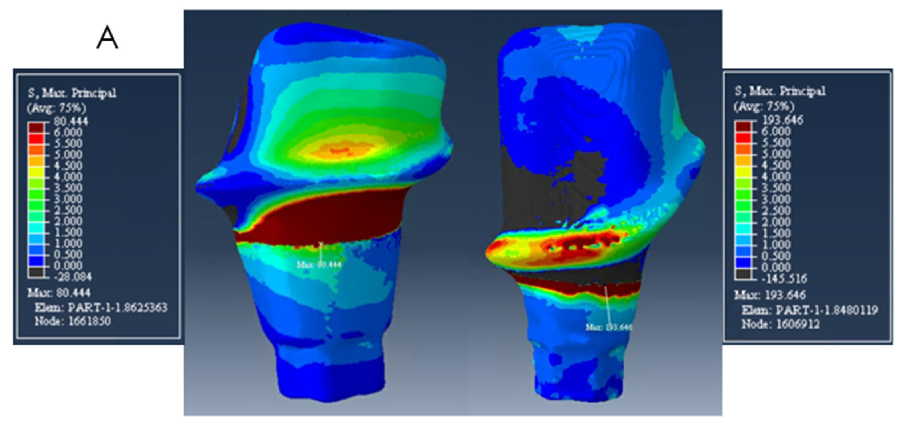
| Mesial abutment | 194 MPa | 140 MPa | 180 MPa |
| Distal abutment | 80 MPa | 56 MPa | 60 MPa |
Publisher’s Note: MDPI stays neutral with regard to jurisdictional claims in published maps and institutional affiliations. |
© 2022 by the authors. Licensee MDPI, Basel, Switzerland. This article is an open access article distributed under the terms and conditions of the Creative Commons Attribution (CC BY) license (https://creativecommons.org/licenses/by/4.0/).
Share and Cite
Alberto, L.H.J.; Kalluri, L.; Esquivel-Upshaw, J.F.; Duan, Y. Three-Dimensional Finite Element Analysis of Different Connector Designs for All-Ceramic Implant-Supported Fixed Dental Prostheses. Ceramics 2022, 5, 34-43. https://doi.org/10.3390/ceramics5010004
Alberto LHJ, Kalluri L, Esquivel-Upshaw JF, Duan Y. Three-Dimensional Finite Element Analysis of Different Connector Designs for All-Ceramic Implant-Supported Fixed Dental Prostheses. Ceramics. 2022; 5(1):34-43. https://doi.org/10.3390/ceramics5010004
Chicago/Turabian StyleAlberto, Laura H. J., Lohitha Kalluri, Josephine F. Esquivel-Upshaw, and Yuanyuan Duan. 2022. "Three-Dimensional Finite Element Analysis of Different Connector Designs for All-Ceramic Implant-Supported Fixed Dental Prostheses" Ceramics 5, no. 1: 34-43. https://doi.org/10.3390/ceramics5010004